

Page 1

IP-421
SERVICE HANDBOOK
March, 2001
Ver. 1.1
KONICA CORPORATION
TECHNOLOGY SUPPORT CENTER
TOKYO JAPAN
KCSI42110
Page 2

COPYRIGHT ©2001
KONICA CORPORATION
All rights reserved
MF13JA1780
Page 3
Safety and Important Warning Items
SAFETY AND IMPORTANT WARNING ITEMS
Read carefully the Safety and Important Warning Items described below to understand them before
doing service work.
IMPORTANT NOTICE
Because of possible hazards to an inexperienced person servicing this equipment, as well as the
risk of damage to the equipment, Konica Corporation, strongly recommends that all servicing be
performed only by Konica-trained service technicians.
Changes may have been made to this equipment to improve its performance after this service
handbook was printed. Accordingly, Konica Corporation, makes no representations or warranties,
either expressed or implied, that the information contained in this service handbook is complete or
accurate. It is under-stood that the user of this service handbook must assume all risks or personal
injury and/or damage to the equipment while servicing the equipment for which this service handbook is intended.
Therefore, this Service Handbook must be read carefully before doing service work both in the
course of the technical training and even after that, for keeping the correct maintenance and control
of the copying machine. Keep the Service Handbook also for the future service. When it is impossible to read the description about safety and warning (due to contamination or tear), the relevant
page should be re-placed.
DESCRIPTION ITEMS FOR Danger, Warning AND Caution
In this Service Handbook, each of three expressions, “ Danger, Warning and Caution” is
defined as follows together with a symbol mark to be used in a limited meaning.
When servicing, the relevant works (disassembling, assembling, adjustment, repair and maintenance) need to be conducted with utmost care.
Danger: Actions having a high possibility of suffering death or serious
wound
Warning: Actions having a possibility of suffering death or serious wound
Caution: Actions having a possibility of suffering a slight wound, medium
trouble and material damage
C-1 IP-421 PRINT CONTROLLER
Page 4

Safety and Important Warning Items
SAFETY WARNINGS
● MODIFICATIONS NOT AUTHORIZED BY Konica
Konica copiers are renowned for their high reliability. This reliability is achieved through high-quality
design and a solid service network.
Photocopier design is a highly complicated and delicate process where numerous mechanical,
physical, and electrical aspects have to be taken into consideration, with the aim of arriving at
proper tolerances and safety factors. For this reason, unauthorized modifications involve a high risk
of degrading performance and safety. Such modifications are therefore strictly prohibited. The points
listed below are not exhaustive, but they illustrate the reasoning behind this policy.
Prohibited Actions :
(1) Using extension cables or a different power cord than specified by Konica.
(2) Using other fuses than specified by Konica. Safety will not be assured, lead-
ing to a risk of fire and injury.
(3) Disabling fuses or bridging fuse terminals with wire, metal clips, solder or
similar. (This applies also to thermal fuses.)
(4) Removing air filters (except for replacement).
(5) Disabling relay functions (such as wedging paper between relay contacts,
etc.).
(6) Disabling safety functions (interlocks, safety circuits, etc.). Safety will not be
assured, leading to a risk of fire and injury.
(7) Performing actions to copier not described in the instruction manual or the
service handbook.
(8) Using parts other than specified by Konica.
● CHECKPOINTS WHEN PERFORMING ON-SITE SERVICE
Konica copiers are extensively tested before shipping, to ensure that all applicable safety standards are met, in order to protect the customer and customer engineer from the risk of injury.
However, in daily use, any electrical equipment will be subject to parts wear and eventual failure. In
order to maintain safety and reliability, the customer engineer must perform regular safety checks.
Caution :
(1) Wear clothing that facilitates work and is designed for safety.
(2) Carry out all procedures carefully to prevent injury.
(3) Be sure to disconnect the power cord of the copier and all optional equip-
ment from the AC outlet.
Simply turning off the power switch is not sufficient, because paper feed
units or other electrical equipment may be powered also when the power
switch is turned off.
(4) Proceed with special care when performing operation checks or adjustment
while the unit is powered. When carrying out operation checks or adjustment while external covers are removed, the risk of electrical shock exists
when touching parts which carry high voltage or electrical charge. The risk
of injury exists when touching moving parts such as gears or chains.
C-2 IP-421 PRINT CONTROLLER
Page 5

Safety and Important Warning Items
The following list is not exhaustive, but it includes actions which must be carried out at every service call.
Caution :
(1) Check external covers and the frame for sharp edges, burrs, or nicks.
(2) Check external covers and hinges for loosening or damage.
(3) Check wiring for squeezing or damage.
(4) Check power cord for insulation problems (conductor must not be exposed).
(5) Check that power cord is properly connected.
Warning :
(1) Verify that the copier is properly grounded. If a problem is detected, estab-
lish a proper ground connection.
(2) Connecting the ground lead to an improper point such as listed below re-
sults in a risk of explosion and electric shock.
Unsuitable ground points:
- Gas pipe
- Lightning rod
- Telephone line ground
- Plastic water pipe or water pipe or faucet that has not been approved by
authorities for grounding use
● PRECAUTIONS FOR ON-SITE SERVICE
Caution :
(1) Before performing maintenance work, read all relevant documentation (ser-
vice handbook, technical notices, etc.) and proceed according to the prescribed procedure, using only the prescribed tools. Do not carry out any
adjustments not described in the documentation.
(2) If the power cord is damaged, replace it only with the specified power cord.
If the power cord insulation has been damaged and there are exposed sections, shortcircuits and overheating may occur, leading to a serious fire risk.
(3) Do not route the power cord so that it can be stepped on or pinched. Other-
wise overheating may occur, leading to a serious fire risk.
(4) When disconnecting any cables, always grasp the connector and not the
cable (especially in the case of AC and high-voltage leads).
(5) Carefully remove all toner remnants from electrical parts, electrodes, etc.
(6) Make sure that wiring cannot come into contact with sharp edges, burrs, or
other pointed parts.
(7) Double-check to make sure that all screws, components, wiring, connec-
tors, etc. that were removed for maintenance have been reinstalled in the
original location. (Pay special attention to forgotten connectors, pinched
cables, forgotten screws, etc.)
(8) When installation and preventive maintenance, verify that the power cord
has been securely plugged into the AC outlet. Contact problems may lead
to increased resistance, overheating, and the risk of fire.
Warning :
(1) Before disassembling or adjusting the optical unit or any parts that use a
laser, make sure that the power cord has been disconnected.
C-3 IP-421 PRINT CONTROLLER
Page 6

Safety and Important Warning Items
(2) Do not remove the main cover of the write unit. Direct exposure of the eye to
laser beams may lead to blindness.
(3) Do not turn the copier on while the write unit is not installed in its normal
position.
(4) Danger of explosion if battery is incorrectly replaced, replace only with the
same or equivalent recommended by the manufacturer. Discard used bat-
teries according to the manufacture’s instructions.
Vorsicht :
(4) Expiosionsgefahr dei unsachegemäßem Austausch der Battetie. Ersatz nur
durch denselben oder einen vom. Hersteller empfohlenen gleichwertigen Typ.
Entsorgung gebrauchter Batterien nach Angaben des Herstellers.
● HANDLING OF MATERIALS FOR SERVICING
Caution: Drum cleaner (alcohol-based) and roller cleaner (acetone- based) are
highly flammable and must be handled with care.
When using these materials for cleaning of copier parts, observe the
following pre-cautions.
(1) Disconnect the power cord from the AC outlet.
(2) Use only a small amount of cleaner at a time and take care not to spill any
liquid. If this happens, immediately wipe it off.
(3) Perform cleaning only in an environment where sufficient ventilation is assured.
Breathing large quantities of organic solvents can lead to discomfort.
(4) Do not replace the cover or turn the unit on before any solvent remnants on
the cleaned parts have fullyevaporated.
Caution: Toner and developer are not harmful sub-stances, but care must be
taken not to breathe excessive amounts or let the substances come
into contact with eyes etc.
If this happens, immediately rinse with eye wash and plenty of water,
and consult a physician.
● MEASURES TO TAKE IN CASE OF AN ACCIDENT
(1) If an accident has occurred, the distributor who has been notified first must
immediately take emergency measures to provide relief to affected persons
and to prevent further damage.
(2) If a report of a serious accident has been received from a customer, an on-
site evaluation must be carried out quickly and Konica Corporation must be
notified.
(3) To determine the cause of the accident, conditions and materials must be
recorded through direct on-site checks, in accordance with instructions is-
sued by Konica Corporation.
● CONCLUSION
Safety of users and customer engineers has topmost priority, ranking even higher than operability.
Safety depends on a appropriate maintenance work and is maintained by proper daily service work
conducted by customer engineers. When performing service, each copier on the site must be
tested for safety. The customer engineer must verify the safety of parts and ensure appropriate
management of the equipment.
C-4 IP-421 PRINT CONTROLLER
Page 7

Contents
CONTENTS
SAFETY AND IMPORTANT WARNING ITEMS............................................ C-1
1. Overview
■ Product specifications ................................................................................ 1-1
● IP-421 print controller ..................................................................................................... 1-1
■ Product overview ........................................................................................ 1-3
● Capabilities of the IP-421 ................................................................................................ 1-3
● Startup sequence of the 7020 series + IP-421 system ................................................... 1-4
● Data processing of the IP-421 (See data flow) ............................................................... 1-4
● Data flow ......................................................................................................................... 1-5
■ Option ......................................................................................................... 1-6
● KN-303 Network card ..................................................................................................... 1-6
● Hard Disk (HD-103) ........................................................................................................ 1-6
● Post Script 3 (PS-341) .................................................................................................... 1-6
2. Disassembly/Assembly
■ Construction ............................................................................................... 2-1
■ Disassembly / Assembly procedures.......................................................... 2-2
● Removal/Installation of boards........................................................................................ 2-2
● Expanding the memory (MU-403/MU-404/MU-405) ....................................................... 2-5
● Installation / Removal of HD-103 .................................................................................... 2-7
● Installation / Removal of PostScript 3 option (PS-341) ................................................... 2-9
3. Troubleshooting
■ Troubleshooting .......................................................................................... 3-1
● Troubleshooting of the IP-421 and copier ....................................................................... 3-1
4. Appendices
■ Upgrading Firmware ................................................................................... 4-1
● Rewriting the Flash ROM (via Parallel Port) ................................................................... 4-1
● Rewriting the Flash ROM (by removing it) ...................................................................... 4-4
● Comfirming Update ......................................................................................................... 4-2
● Replacing ROM .............................................................................................................. 4-6
■ Functions of parts mounted on boards ....................................................... 4-7
● Connector ....................................................................................................................... 4-8
● Switch ............................................................................................................................. 4-8
● Jumpers .......................................................................................................................... 4-8
● Individual ICs’ functions .................................................................................................. 4-8
INDEX ..................................................................................................... Index-1
C-5 IP-421 PRINT CONTROLLER
Page 8

1
Overview
Page 9

Bkank Page
Page 10

■ Product specifications
● IP-421 print controller
Type: Built in Konica 7020 series copy machine
Paper size: A3, A4, A5, B4, B5, B6, 11"X17", 8.5"x14", 8.5"x11", 5.5"x8.5"
Paper feeding: Same as copier
Output stack capacity: Same as copier
Mode: Possible dual mode of copy machine/printer (up to 5 jobs)
Next job reservation: Next copy job can be reserved during print job.
Special printing features: Printing on both faces, choice of paper type, zoom
Chapter 1 Overview
function, choice of paper tray, choice of output tray,
choice of print quality, Alternate function, sort/
group function, staple function, layout function,
front/back cover intersheet function, booklet function, smoothing function, page protection function,
watermark function
Direction of printing: portrait, landscape
Resolution: 600 dpi
Scan Resolution: 600 dpi/400 dpi/300 dpi/200 dpi
Gradation: 2
Number of output pages: 1-999
Warm-up: Same as copier
CPU: Pentium MMX-166Mhz
Memory: 32MB (standard), expandable up to 160MB (option:MU-403 / MU-
404 / MU-405)
Cards: Controller board x1
PCI relay board x1
KN-303 Network card (option)
Option:Harddisk Drive (HD-103)
PS option (PS-341)
1-1 IP-421 PRINT CONTROLLER
Page 11

Chapter 1 Overview
Interface: Parallel port
Based on Centronics (IEEE 1284)/Amphenol male 36pin connector
Network interface: (option)
KN-303 Network card
Network: Ethernet (100BaseTX/10BaseT)
Protocols: IPX/SPX (NetWare),
TCP/IP (LPD/LPR, peer-to-peer)
AppleTalk (EtherTalk)
Compliant OS:
Windows 95/98
Windows NT4.0/2000
Macintosh
Unix
Printer Language:
PCL
PostScript3 (option)
Printer drivers:
Windows 95/98 printer driver
Windows NT4.0/2000 printer driver
Host computer: A Windows based computer
Macintosh
Unix
Finisher: FS-107
paper tray unit: DB-209,DB-409
Size: 240 mm(W) x 160 mm(H) x 37 mm(D)
Weight: Approx. 1.1 kg
Power source: 5 V, 2 A or less (supplied from copier)
Operating conditions:temperature: 10-30˚C,
humidity: 20-80%RH (condensation not allowed)
Restrictive Conditions:
1-2 IP-421 PRINT CONTROLLER
• In the Printer mode, the EKC (Electric Key Counter) of the Konica
7020 series is not available.
• Although the Weekly Timer function of the Konica 7020 series is
available in the Printer mode, the power is not turned Off until
the data output is finished when print data remains in the E-RDH.
Notice: Specifications are subject to change for improvements without no-
tice.
Page 12
Chapter 1 Overview
■ Product overview
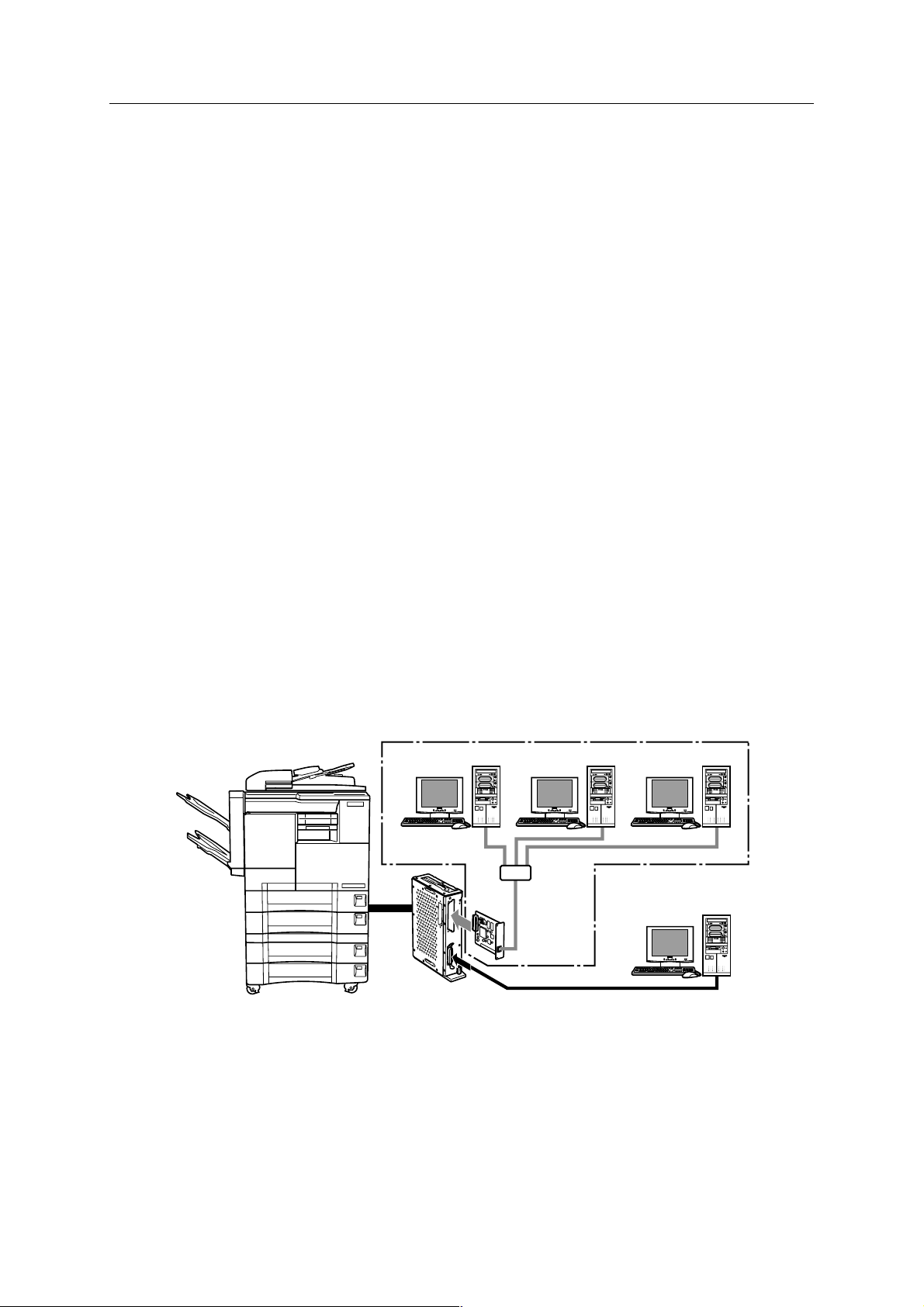
● Capabilities of the IP-421
The Konica IP-421 print controller allows you to use the Konica 7020 series copying machine as a
printer connected to computers and a network. It receives print jobs from computers and network
and converts them into image data (video data) that the Konica 7020 series copying machine prints
out.
The IP-421 print controller is characterized as follows.
• Built in the Konica 7020 series copying machine.
• The drivers interfacing with Windows 95/98 and NT4.0/2000 allow use of the
functions of the Konica 7020 series copying machine.
• The KN-303 Network card allows use of the IP-421 as a network printer.
• A system can be upgraded by the renewal of the flash memory.
This Service Handbook describes hardware construction, disassembly and assembly procedures,
troubleshooting, and appendixes (upgrading firmware, error messages, etc).
IP-421
KN-303
(OPTION)
1-3 IP-421 PRINT CONTROLLER
Page 13

Chapter 1 Overview
● Startup sequence of the 7020 series + IP-421 system
As the IP-421 is built in the 7020 series, supplying power to the IP-421 and its initialization starts as
soon as you turn on the copier. The startup sequence is as follows.
1. Turn on the copier.
Supplying power to start the IP-421 starts. Its CPU works to test the system memory
and the system program starts running.
2. The IP-421 performs system check.
3. On completion of system check, the controller is waiting print job.
If printer mode is selected, a message “Ready to print” appears.
● Data processing of the IP-421 (See data flow)
When you attempt to print a document data from a computer connected the IP-421, processing will
be made as follows.
1. The print job comes from the computer (or network) to the parallel port (or Ethernet port if
the KN-303 is used).
2. The CPU, mounted on IP-421, generates the bit map image of one page to another in the
image memory.
3. The bit map image is transferred in the form of video signals from the image memory to the
copier and printed.
1-4 IP-421 PRINT CONTROLLER
Page 14

● Data flow
Chapter 1 Overview
Print Commands
Interface
Print Controller
IP-421
Computer
Spooler
Parallel I / F(IEEE1284)
Parallel I / F
Application
Printer Driver
Browser
HTML
Ethernet I/F
(TCP/IP,IPX/SPX)
Network Card KN-303
(Option)
PCI bus
Input Buffer
Printer Engine
PDL command
Rasterized graphic data
Printer status
Harddisk HD-103
(Option)
PDL Processing (Rasterization)
Graphic memory
PCI bus
E-RDH memory
Engine(Print)
1-5 IP-421 PRINT CONTROLLER
Page 15

Chapter 1 Overview
■ Option
● KN-303 Network card
If the IP-421 is fitted with the KN-303 Network card, the 7020 series can be used as a remote printer
from any computer belonging to a network (NetWare/Windows).
● Hard Disk (HD-103)
By installing this optional hard disk to the IP-421, you can use the 7020 series copier as a scanner.
The scanned data can be read into your PC via an optional Network Interface Card.
● Post Script 3 (PS-341)
By installing this optional PostScript and the standard compact flash for PostScript to the IP-421,
you can use the 7020 series copier as a PostScript printer.
1-6 IP-421 PRINT CONTROLLER
Page 16

2
Disassembly / Assembly
Page 17

Bkank Page
Page 18

■ Construction
Chapter 2 Disassembly / Assembly
Expansion memory slot
PDL compact flash slot
Controller Board
PS compact flash slot
CPU cooling fan
Tool
PCI relay
board
Printer reray board
PS-341 slot
HD-103 connector
Parallel port connector
(CN502)
Caution:
If grounding is not made securely, the cards can be damaged during work. Make
sure to ground your body securely by using a wrist strap before starting to work.
• Use a Phillips head screwdriver.
Reference information:
As the IP-421 is provided with a “flash memory”, no tool is needed to replace ROM
for upgrading the firmware.
2-1 IP-421 PRINT CONTROLLER
Page 19

Chapter 2 Disassembly / Assembly
■ Disassembly/Assembly procedures
● Removal/Installation of boards
1. Remove the sliding cover. (2 screws)
Sliding cover
2. Remove the Board cover. (11 screws)
Board cover
3. Remove the side cover of the parallel connector side. (5 screws)
2-2 IP-421 PRINT CONTROLLER
Side cover
Page 20

4. Remove the printer relay board. (5 screws)
5. Remove the Board cover fixtures. (6 screws)
Chapter 2 Disassembly / Assembly
Board cover fixtures
Board cover fixtures
6. Remove the controller board unit and the side cover of the copying machine side all to-
gether.(9 screws)
2-3 IP-421 PRINT CONTROLLER
Page 21

Chapter 2 Disassembly / Assembly
7. Pull off the controller board at the connector (CN2) on the PCI relay board fitted to the side
cover.
CN2
8. Remove the PCI relay board. (6 screws)
CN4
9. To install, reverse the removal procedure.
Caution:
When installing the PCI relay board, be sure to securely plug in connectors (2 in
number).
2-4 IP-421 PRINT CONTROLLER
Page 22

Chapter 2 Disassembly / Assembly
● Expanding the memory (MU-403/MU-404/MU-405)
The IP-421 is provided with 32MB memory (standard specification). You can expand the memory
capacity up to 160MB by installing a DIMM card additionally into a slot on the controller board.
Caution:
• With the memory expanded, the IP-421 can rasterise more pages during waiting
previous print job than before expansion.
• If memory overflow occurs, expand the memory.
• The memory card slot is prepared for expansion of 32MB, 64MB or 128MB.
• When a memory except for Konica designation, the movement of IP421 can’t be
assured.
Installing DIMM
1. Insert the connector of DIMM obliquely.
2-5 IP-421 PRINT CONTROLLER
Page 23

Chapter 2 Disassembly / Assembly
2. Push the end of the DIMM and lock it with levers provided on both sides of the socket.
Caution:
The DIMM card can fit into the socket only in such a direction that the notch provided on the bottom of DIMM matches with the one on the socket.
Removing DIMM
1. Release the lock levers provided on both sides of the socket. Take out the DIMM in the
upper oblique direction.
2-6 IP-421 PRINT CONTROLLER
Page 24

● Installation / Removal of HD-103
1. Remove the Board cover on the IP-421. (11 screws)
2. Remove the printer relay board. (3 screws), then remove the flash card stopper plate. (2
screws)
Printer relay board
Chapter 2 Disassembly / Assembly
Board cover
Flash card
stopper plate
3. Connect the HDD to the connector of the printer relay board.
Caution:
Take care not to bend or break the pins of HDD.
HDD
Printer relay board
2-7 IP-421 PRINT CONTROLLER
Page 25

Chapter 2 Disassembly / Assembly
4. Fix the HDD on the printer relay board with 4 screws.
5. Fit the printer relay board into the connector of the IP-421 print controller.
Printer relay board
6. Fix the flash card stopper plate with two screws, then fix the printer relay board with three
screws.
7. Fix the board cover on the IP-421. (11 screws)
8. To remove, reverse the installation procedure.
2-8 IP-421 PRINT CONTROLLER
Printer relay board
Flash card
stopper plate
Page 26

Chapter 2 Disassembly / Assembly
● Installation / Removal of PostScript 3 option (PS-341)
1. Remove the Board cover on the IP-421. (11 screws)
Board cover
2. Remove the printer relay board. (3 screws), then remove the flash card stopper plate. (2
screws)
Printer relay board
Flash card
stopper plate
3. Mount the Flash card on the printer relay board.
Caution:
Position the Flash card in correct direction as illustrated below.
2-9 IP-421 PRINT CONTROLLER
Page 27

Chapter 2 Disassembly / Assembly
4. Mount the PS-341 on the print controller board.
Caution:
Position the PS-341 by matching the cut corner to that on the board.
5. Fit the printer relay board into the connector of the IP-421 print controller.
PS-341
Printer relay board
6.
Fix the flash card stopper plate with two screws, then fix the printer relay board with three screws.
Printer relay board
Flash card
stopper plate
7. Fix the board cover on the IP-421. (11 screws)
8. To remove, reverse the installation procedure.
Caution:
To remove the PS-341, use a PLCC removing tool.
2-10 IP-421 PRINT CONTROLLER
Page 28

3
Troubleshooting
Page 29

Bkank Page
Page 30

Chapter 3 Troubleshooting
■ Troubleshooting
This section offers a summary of information on troubleshooting that technicians could refer to
easily and would minimize the time of interruption of work.
● Troubleshooting of the IP-421 and copier
Symptoms
Printer mode window does not
appear on the copier’s display
after power-on.
“Warming up” does not disappear.
“Initialization ” does not disappear on the copier screen.
Printout is defective, or nothing
can be printed.
IP-421 does not start.
Causes
No power supply to the IP-421.
Copier is in trouble.
The IP-421 has not started properly.
The controller board or some
boards of the copier are defective.
The controller board is inactive.
Actions
Check if the IP-421 is connected
with the copier properly.
Locate the cause of trouble of
the copier.
See the column of “IP-421 does
not start”.
Put the copier in 36 mode and
perform test. If it operates properly, controller board may be
failure.
Check the connector of the controller board. Replace the controller board as necessary.
Test print can be produced but
not from the parallel port.
Software of the IP-421 is destroyed.
The parallel port has something
wrong or the cable is wrong
or, the problem is on the computer side.
Reinstall the software of the IP-
421.
Check the cables (internal/external). Perform test using a
data generator or a well-proven
PC/I/O cable. Replace the controller board as necessary.
3-1 IP-421 PRINT CONTROLLER
Page 31

Chapter 3 Troubleshooting
Symptom
Test print can be produced but
not from the network port.
Test print can be produced and
all ports are good, but user jobs
cannot be printed.
Troubleshooting Flowchart for Removing Print Troubles
Can be printed
out from other
computers.
No
Possible causes
The network card is inactive or
not installed properly.
Some software error has happened.
Ye s
Actions
Examine the network card. Check
all connectors. Replace the network card as necessary.
IP-421’s software or application
program has something wrong.
Save the file, which failed to be
printed, in the disk and analyze
the problem by suitable means.
Remove the driver,
then reinstall it.
HD-103
is installed.
No No
Ye s
Can be printed out
after having formatted
the hard disk.
Can be printed out
after having rewritten the
Compact Flash ROM.
No
No trouble in
operation test with the
copier in its 36 mode.
No
Try to find the
cause of the trouble
in the copier.
Ye s
Ye s
Ye s
Normal Condition
Normal Condition
Replace the
controller board.
3-2 IP-421 PRINT CONTROLLER
Page 32

4
Appendices
Page 33

Bkank Page
Page 34

Chapter 4 Appendices
■ Upgrading Firmware
The IP-421 is equipped with a compact flash ROM and lets you upgrade the firmware in one of two
ways: you can overwrite it via the parallel port, with the compact flash ROM left inside, or you can
take out the compact flash ROM to overwrite the firmware.
● Rewriting the Flash ROM (via Parallel Port)
Please follow the procedures below for normal operation.
In advance, make sure that:
• The parallel port is set to ECP mode in the computer’s BIOS setup.
• The Print Controller’s banner page is set to OFF (default).
• Print Controller must be connected to Hard disk that is available for more than 10MB.
(If necessary, you have to format the HDD or delete unnecessary data.)
• Unplug the network cable, if connected.
• Check to see whether no jobs are waiting to be output, as confirmed by the job reservation
list.
Setting up PC for [ECP]
1. Be sure that parallel port mode is set to [ECP] in LPT1 setting.
2. Starting up Windows, and then, click [Start] button to select [Printers] in [Settings].
3. Click the printer icon selected by default setting and then right click to choose
[Properties].
4. Click [Details] tab and then be sure that [ECP printer port] is selected in [Print to
the following port] field.
5. Click [Port Settings] in the property dialog box to check that the following settings
are selected. Then click [OK].
[Spool MS-DOS print jobs] [Check port state before printing]
6. Click [Apply] and then [OK].
Follow the above procedures, PC setup is correctly completed.
4-1 IP-421 PRINT CONTROLLER
Page 35

Chapter 4 Appendices
Procedure
1. Connect a parallel cable between the computer and Print Controller.
2. Turn on the Copier’s main power.
Wait about 5 minutes if a network interface card is in use.
3. Press the [SCANNER/PRINTER] button on the operation panel to switch to Printer Mode
Basic Screen.
4. Press the [SETTING] key when it comes on the screen.
The Printer Menu Screen will appear.
5. When the Printer Menu Screen appears, open a DOS prompt on the computer, and enter
the following command before pressing the Enter key.
Command: C:\copy filename.xxx lpt1 /b
The message [Updating...] will appear on the Copier’s LCD panel and at the same time an
LED will start blinking on the operation panel.
NOTE:
Do not operate the computer and Copier while the message [Updating...] is displayed
on the Copier’s LCD panel.
If, when this message is displayed, you turn off the Copier, the Print Controller may
be damaged.
4-2 IP-421 PRINT CONTROLLER
Page 36

Chapter 4 Appendices
6. When the updating process is complete, the message [Update Completed!] will show and
at the same time the LED will stop blinking. Then turn the power off and on.
If 15 minutes or so go by and the updating process does not complete, errors may
occur. In this case turn the power off and on, and retry from the beginning.
(The upgrading process time depends on the performance of the individual comput-
ers.)
When an error develops during the upgrading process, the former version of firmware
is left as it is: its upgrade is not installed.
Limitations:
The Print Controller’s system software update has no guarantees about its perfor-
mance under the following conditions during the update process. In many cases the
software may not be correctly read in and it cannot be started.
• The machine is operating or there exist reserved jobs.
• Such modes are activated as 25/36/47, Key Operator mode, Service
Mode or Interruption Mode.
• The E or F error conditions exist, or a jam is produced.
4-3 IP-421 PRINT CONTROLLER
Page 37

Chapter 4 Appendices
■ Rewriting the Flash ROM (by removing it)
You can also upgrade the firmware by taking out the ROM.
If you cannot upgrade the firmware via parallel port as discussed above, perform the following
procedures to take out the ROM and upgrade the firmware.
This procedure necessitates a notebook computer (with Windows 95/98 or NT4.0/
2000 installed) and a PCMCIA-Compactflash adapter.
1. Remove Flash card stopper plate on printer relay board (2 screws).
2. Remove the Compact Flash card.
3. Insert the Compact Flash card into the PCMCIA-Compactflash adapter, plug it into the
PCMCIA slot on the notebook computer, and then use the Windows explorer or the like to
check to see whether the Compactflash card is identified by the computer as a drive.
If the Compact Flash adapter is not identified by the computer, refer to the manual for
your computer or that for Compact Flash adapter.
4. Using the explorer, select the Compact Flash card drive to perform formatting.
5. Using the explorer, select the configuration folder and all its files from the source firmware
folders, and then make a copy of them.
4-4 IP-421 PRINT CONTROLLER
Page 38

Chapter 4 Appendices
6. Using the explorer, select the Compact Flash card drive, and paste the copied folder and
files.
7. Remove the PCMCIA-Compactflash adapter from the computer.
WARNING:
It is imperative that you should perform the following procedures before removing
PCMCIA-Compactflash adapter. Otherwise, data inside the Compact Flash card is
not guaranteed about its correctness.
1. Click the Windows [Start] button, select [Control Panel] from the [Settings] submenu,
and then double-click [PC Card (PCMCIA)].
2. Select the PCMCIA-Compactflash card from the list, click [Stop] or [Completed],
then click [OK].
3. When the message [This device can be removed safely] appears, click [OK].
8. Remove the Compact Flash card from the PCMCIA-Compactflash adapter, and replace
the Compact Flash card to it original location in the Print Controller.
9. Mount the Flash card stopper plate.
4-5 IP-421 PRINT CONTROLLER
Page 39

Chapter 4 Appendices
● Confirming Update
You can print out information on the configuration to check to see whether the update is successfully installed.
1. Press the [Setting] key to access the Printer Menu screen, press a numeric key that corre-
sponds to [Test Print Menu], that is key 1, and press the [OK] key.
2. Press numeric key 3, a key corresponding to [Config.Data], and press the [OK] key.
The configuration data will be printed out.
3. Read the version number on the printout to confirm that the firmware has been updated.
Alternatively, you can also confirm the update by accessing the ROM version display by putting the
Copier in its 25 mode.
4-6 IP-421 PRINT CONTROLLER
Page 40

■ Functions of parts mounted on boards
CN1
CN8
Memory
Oscillator
Chapter 4 Appendices
PCIset
CN7
KPC01
PPBC
SW2
Clock Generator
JP2
Boot ROM
PCIset
JP3
CN3
CPU
SW1
CN4
CN9
CN5
4-7 IP-421 PRINT CONTROLLER
Page 41

Chapter 4 Appendices
● Connector
CN1: Expansion memory
CN3: PS-341 (option)
CN4: Printer relay board
CN5: Printer relay board
CN7: PCI relay board
CN8: PCI relay board
CN9: Parallel port connector
● Switch
SW1: Resets system. (only for development purpose) No need to operate the switch.
SW2: Switch boot system. (only for development purpose) No need to use the switch.
● Jumpers
No need to use the jumpers.
JP2: Not installed (no function)
JP3: For production purpose
● Individual ICs’ functions
CPU: Central processing unit
BootROM: System booting-up parameter
KPC01: Image rotation through 90 degrees/error diffusion processing
PPBC: Bridge from each PCIset to the PCI bus
PCIset: Bridge from different points to PPBC
4-8 IP-421 PRINT CONTROLLER
Page 42

INDEX
INDEX
A
Assembly....................................................... 2-2
B
boards ........................................................... 4-7
C
Connector...................................................... 4-8
Construction .................................................. 2-1
D
Data flow ....................................................... 1-5
DIMM..................................................... 2-5, 2-6
Disassembly .................................................. 2-2
E
Expanding the memory ................................. 2-5
F
R
ROM ....................................................... 4-1, 4-4
S
SAFETY AND IMPORTANT
WARNING ITEMS .................................. C-1
specifications................................................. 1-1
Startup sequence .......................................... 1-4
Switch............................................................ 4-8
T
Troubleshooting ............................................. 3-1
Firmware ....................................................... 4-1
flash memory ................................................ 1-3
Flash ROM .................................................... 4-1
H
HD-103 ...................................................1-6, 2-7
I
IC ............................................................... 4-8
J
Jumpers ........................................................ 4-8
K
KN-303 .......................................................... 1-6
M
MU-403 ......................................................... 2-5
MU-404 ......................................................... 2-5
MU-405 ......................................................... 2-5
P
PostScript 3 option ........................................ 2-9
Protocols ....................................................... 1-2
PS-341 ...................................................1-6, 2-9
Index-1
 Loading...