

Page 1

™
0
EV-jetsetter RIP
ProofReady plugin for 6-Color HP
Printers
Version 1.0
November 2002
AG50324P3 Rev. 3
Page 2

ii
Copyright and Trademarks
Harlequin RIP: ProofReady Plugin for 6-Color HP Printers
Version 1.0
November 2002
Part number: HQ-1.0.3-PROOFREADY-HP6col-ECLIPSE
Copyright © 1992–2002 Global Graphics Software Limited.
All Rights Reserved. No part of this publication may be reproduced, stored in a retrieval system, or transmit-
ted, in any form or by any means, electronic, mechanical, photocopying, recording, or otherwise, without the
prior written permission of Global Graphics Software Limited.
The information in this publication is provided for information only and is subject to change without notice.
Global Graphics Software Limited and its affiliates assume no responsibility or liability for any loss or damage that may arise from the use of any information in this publication. The software described in this book is
furnished under license and may only be used or copied in accordance with the terms of that license.
ScriptWorks is a registered trademark and Harlequin, the Global Graphics Software logo, Harlequin RIP,
ColorPro,
EasyTrap, FireWorks, FlatOut, Harlequin Color Management System, HCMS, Harlequin Color
Production Solutions, HCPS, Harlequin Color Proofing, HCP, Harlequin Full Color System, HFCS, Harlequin
ICC Profile Processor, HIPP, Harlequin Standard Color System, HSCS, Harlequin Chain Screening, HCS, Harlequin Dispersed Screening, HDS, Harlequin Micro Screening, HMS, Harlequin Precision Screening, HPS,
Harlequin Screening Library, HSL, Harpoon, RipFlow, ScriptWorks MicroRIP, ScriptProof, ProofReady, Scalable Open Architecture RIP, SOAR, SetGold, SetGoldPro, TrapMaster, TrapPro, TrapWorks, PDF Creator and
RIPFlow are all trademarks of Global Graphics Software Limited.
Portions licensed under U.S. Patents: Nos. 4,500,919, 4,941,038 and 5,212,546. EasyTrap is licensed under one
or more of the following U.S. Patents: Nos. 5,113,249, 5,323,248, 5,420,702, 5,481,379.
Adobe, Adobe Photoshop, Adobe Type Manager, Acrobat, Display PostScript, Adobe Illustrator, PostScript,
Distiller and PostScript 3 are either registered trademarks or trademarks of Adobe Systems Incorporated in
the United States and/or other countries which may be registered in certain jurisdictions.
Global Graphics Software Limited is a licensee of Pantone, Inc. PANTONE
are four-color process simulations and may not match PANTONE-identified solid color standards. Consult
current PANTONE Color Publications for accurate color. PANTONE
CALIBRATED
™
are trademarks of Pantone, Inc. © Pantone, Inc., 1991.
®
Colors generated by ScriptWorks
®
, Hexachrome
®
, and PANTONE
Other brand or product names are the registered trademarks or trademarks of their respective holders.
US Government Use
The ScriptWorks software is a computer software program developed at private expense and is subject to the following Restricted Rights
Legend: “Use, duplication, or disclosure by the United States Government is subject to restrictions as set forth in (i) FAR 52.227-14 Alt III or
(ii) FAR 52.227-19, as applicable. Use by agencies of the Department of Defense (DOD) is subject to Global Graphics Software’s customary
commercial license as contained in the accompanying license agreement, in accordance with DFAR 227.7202-1(a). For purposes of the FAR,
the Software shall be deemed to be `unpublished’ and licensed with disclosure prohibitions, rights reserved under the copyright laws of the
United States. Global Graphics Software Incorporated, 95 Sawyer Road, Waltham, Massachusetts 02453.”
AG50324P3 Rev. 3
Page 3

Table of Contents
1.1 Introduction 1
Requirements 2
Capabilities of the plugin 4
Limitations 4
1.2 Software installation 5
Installing the OS support software and printer 5
Installing the RIP and the ProofReady plugin 6
Using the installer 6
1.3 Connecting to the printer 8
1.4 Getting started 9
Entering passwords 10
Creating device types 11
Creating a page setup 11
1.5 Supplied profiles 18
Halftone screen selection 19
1.6 Device configuration 20
Output file naming 25
Post processing 33
1.7 Routine use 36
Page setup controls 36
Roaming page buffers 39
1.8 Color management 40
Calibration 40
Creating and installing ICC profiles 44
Creating a HIPP or ColorPro color setup 46
Using the Harlequin Full Color System (HFCS) 47
AG50324P3 Rev. 3 iii
Page 4

iv
1.9 Troubleshooting and tips 47
Miscellaneous messages 47
Printer-specific messages and symptoms 49
Messages for file name templates 53
Messages for post processing 55
Parallel port performance and reliability 56
Problems with passwords 57
Patterning when not using color management 57
Sending files to a printer using Windows printer drivers 58
1.10Related documentation 59
AG50324P3 Rev. 3
Page 5

1
ProofReady Plugin for 6-Color
1
HP Printers
This document describes the ProofReady plugin version 1.0r3, for use with a
Harlequin RIP, version 5.3 or later. This plugin is provided with pre-configured color setups and calibration profiles that enable instant color
management, hence the name ProofReady. The plugin is available for the RIP
running on Pentium-based processors using either Windows NT,
Windows 2000, Windows 98 or Windows ME and for the Harlequin RIP running on Macintosh computers, including Mac OS X (support for Mac OS X
requires Harlequin RIP version 5.5r1w or later).
1.1 Introduction
The ProofReady plugin allows the RIP to provide page images to a supported
HP printer.
RIP or through a suitable network or interface adapter, as specified in this
document. You can also print to file and transfer this file for output to a
printer.
1.
Note : HP, Hewlett-Packard, and DESIGNJET are registered trademarks of the Hewlett-
Packard Company.
1
The printer can be connected directly to the computer running the
AG50324P3 Rev. 3
1
Page 6

2
1 ProofReady Plugin for 6-Color HP Printers
The following printers are supported but it may also be possible to use other
models produced to be directly compatible with these printers:
• HP DesignJet 5000 (42" and 60" wide models)
All of the printers can be used with sheet-fed or roll-fed media. You can
choose to output in a 4-color mode (Contone), which sends CMYK data to the
printer and uses the default screening for the device to calculate the Cyan
Light and Magenta Light components. Alternatively you can output in a 6color mode (PhotoInk) using HDS screening (Harlequin Dispersed Screening).
The device type that you use when creating a page setup determines the
paper handling and the color mode used by the printer. See “Creating device
types” on page 11 for full details.
1.1.1 Requirements
If you intend to produce large format or high-resolution pages you may need
to add extra physical memory (RAM) and you must allow sufficient disk
space. To use the
computer fitted with at least 128 MB of RAM.
To allow the preview of large pages and to optimize the transfer of data to the
printer, increase the
or larger. Increase the
dialog box to approximately 10 MB.
If using a Macintosh computer the
Configure RIP Options dialog box must be at least 10000 KB. To avoid
memory warnings and to increase performance assign approximately 64 MB
of memory to the RIP. To do this use the menu option
play the memory information. Set the preferred size to your chosen value.
The computer must have a suitable interface with which to drive the printers.
See Section 1.3 on page 8 for a summary of possible connection methods.
Describing the details of hardware installation for the printers and external
hardware is outside the scope of this manual. See the manufacturer’s documentation for details.
Multiple (Parallel)
Printer buffer
Disk space left for system
in the Configure RIP dialog box to 4096 KB
Minimum memory left for system
mode of the RIP with large files, use a
in the Configure RIP Options
in the
File > Get Info
and dis-
AG50324P3 Rev. 3
Page 7
1.1 Introduction
The supplied package includes color management profiles for use with HDS
Super Fine screens which are required when using the 6-color printing mode.
To use these profiles HDS Light or HDS must be enabled. Color management
profiles are also supplied to support the 4-color printing mode, which uses the
default screening for the device.
The use of both the 4-color and 6-color profiles requires a color management
option such as HIPP (Harlequin ICC Profile Processor) or Harlequin
ColorPro
™
(Eclipse Release
™
or later of the Harlequin RIP).
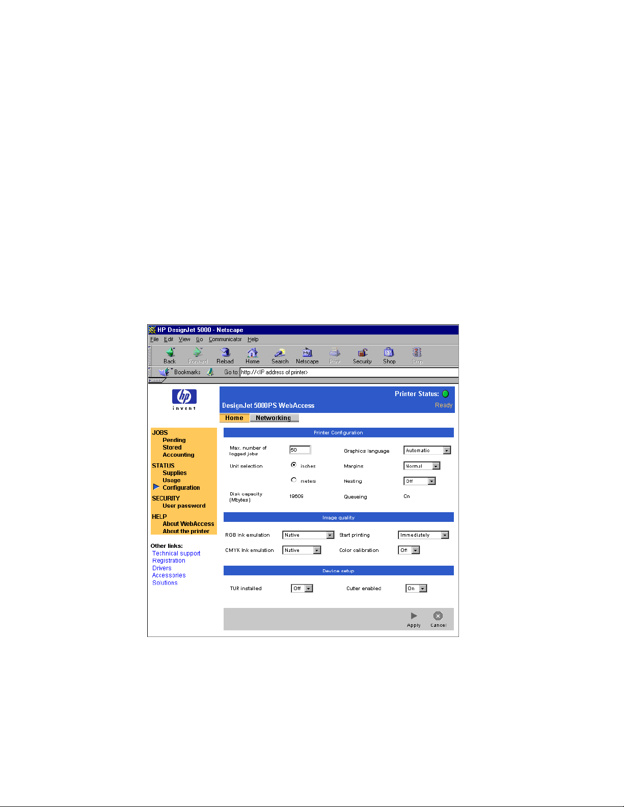
To use both the 4-color and 6-color profiles, you must ensure that the
calibration
control for the printer is set to
Off
. You can access this control by
Color
entering the IP address of the printer in a web browser, as shown in Figure 1.1.
Figure 1.1 Using WebAccess to turn off Color calibration
AG50324P3 Rev. 3 3
Page 8

1 ProofReady Plugin for 6-Color HP Printers
1.1.2 Capabilities of the plugin
The plugin has the following capabilities:
• Instant color management using supplied profiles
• PhotoInk 6-color output on appropriate printers
• A choice of resolution for the output page image for all media sizes and
types supported by the model of printer in use
• User choice of output quality
• Availability of Harlequin’s screening techniques
• Preview of the screened output
4
• Ability to perform post processing
1.1.3 Limitations
The ProofReady plugin generates an output color format that the printer can
accept. This format is 6-color PhotoInk composite or CMYK composite, as
required by the relevant printer, and screened using one of several screening
options.
The 6-color PhotoInk format imposes the following restrictions:
• No use of trapping using EasyTrap. You must use TrapWorks 5.5r0 or
later or TrapPro to trap PhotoInk formats. Note that TrapWorks and
TrapPro treat light inks as separate colors rather than creating a single
trap for all inks of the same color. For example, Cyan and Cyan light are
trapped separately.
• The plugin cannot be run on a Macintosh computer that has NuBus
slots only. This limitation is typically restricted to Macintosh computers
that were manufactured before 1996.
AG50324P3 Rev. 3
Page 9

1.2 Software installation
1.2 Software installation
Harlequin strongly recommends that you install this plugin in a new installation of the RIP. In particular , you are very likely to experience irregular behavior if you install version 1.0r2 or later of the plugin in an installation where
you have previously installed a Plotters plugin, or an earlier version of this
plugin.
There are several stages to the installation of a working system. These are:
• Install any required operating system support
• Install the RIP, if required
• Install the plugin
1.2.1 Installing the OS support software and printer
Do not install software supplied with the printer on a computer running the
RIP unless you wish to use the printer directly from the operating system. The
RIP operates independently of software installed to work with the operating
system. If you do try to use both applications, you are likely to get spurious
messages from the operating software about paper out or similar error
conditions.
There is one exception:
• You must install Windows printer drivers on a PC print server if you
wish to use the print spooling facility provided by Microsoft Windows.
There are advantages and disadvantages to using this output method.
See “Sending files to a printer using Windows printer drivers” on
page 58 for details.
Follow the manufacturer’s recommendations about the order of installing
hardware and software. Make any test prints that the procedure suggests in
order to test that the support software and printer are working correctly.
Before you send real output to your newly-installed printer, follow any procedures that the user guide for the printer suggests to ensure proper ink flow
and correct print head alignment.
AG50324P3 Rev. 3 5
Page 10

1 ProofReady Plugin for 6-Color HP Printers
1.
2.
3.
4.
1.
1.2.2 Installing the RIP and the ProofReady plugin
Read the Harlequin RIP Installation Guide for your platform to see the requirements and procedure for installing the Harlequin RIP. The plugin may be supplied as part of your standard RIP installation media. If so you can install both
the Harlequin RIP and the ProofReady plugin at the same time, as described
in Section 1.2.3 on page 6.
If you receive separate installation media, or an updated plugin, either install
it using the installer, as described in Section 1.2.3 below, or manually as
follows:
Install the RIP, if this is a new installation.
Set appropriate configuration options for the RIP using the guidelines
given in “Requirements” on page 2.
6
Exit the RIP, if you have been using it.
Copy the
hp6col
folder to the
Devices
folder within the RIP’s
SW
folder.
If you have correctly installed the plugin, a line similar to the following will
appear in the RIP monitor when you next start up the RIP:
% ProofReady - HP 6-Color:
Plugin Version 1.0r3 - Copyright (c) 1999-2001 Global
Graphics Software Ltd. All Rights Reserved.
If your computer is already connected to your output device, refer to “Getting
started” on page 9. Otherwise, see “Connecting to the printer” on page 8 for
details of connection methods.
1.2.3 Using the installer
The procedure below describes how to use the installer to install both the
Harlequin RIP and the ProofReady plugin at the same time. If you have
already installed your RIP, just follow the instructions on how to install the
plugin:
Place the media holding the software in an appropriate drive, which will
usually be a CD-ROM drive.
Locate and run the installer for your platform:
AG50324P3 Rev. 3
Page 11

2.
3.
4.
5.
. 6.
1.2 Software installation
PC Run
install.exe
at the top level of the distribution
using Windows Explorer.
Classic Macintosh
Double-click the icon of the drive that holds the
software. Run
install-macos9
at the top-level of the
distribution.
Mac OS X Double-click the icon of the drive that holds the
software. Run
install-macosx
at the top-level of the dis-
tribution.
Check the default location of the
Destination Folder
. This folder should be
the location where you wish the Harlequin RIP to be installed, or where
it is already installed, if you are installing the plugin into a pre-installed
RIP.
If you wish to choose another location, type the path in the
box, or click
Change Folder
. You can type the name of a new folder if you
Folder
text
wish to create one, provided that the disk or volume name is valid. The
installer displays the amount of space available on your chosen disk.
To install the Harlequin RIP , first choose the Harlequin RIP
Package
, and
then choose the exact type of RIP that you wish to install from the
Product
list. Click
Add
to add the product to the install list.
Note that you can refer to the
Product Description
section on the installer
window to see details of what will be installed.
To install the ProofReady plugin for 6-Color HP printers, first choose the
the
Optional Plugins
product. Click
Add
When you have finished adding products to the install list, click
package, and then choose the
HP 6-color Plugin
to add the product to the install list.
Install
If you are installing the ProofReady plugin into a pre-installed RIP and
you have not specified the RIP installation folder as the
Folder
, a Select folder containing RIP dialog box appears.
Destination
Use this dialog box to navigate to and highlight the installation folder of
OK
your RIP, and then click
AG50324P3 Rev. 3 7
.
Page 12
1 ProofReady Plugin for 6-Color HP Printers
7.
The installer installs the Harlequin RIP (if you chose to install it in
step 3) and copies the plugin files into the relevant locations within the
RIP installation folder. At the end of the copying, the installer displays a
Product Installer window with the message
Click
OK
to close the window and exit the installer.
If you have correctly installed the plugin, a line similar to the following will
appear in the RIP monitor when you next start up the RIP:
ProofReady - HP 6-Color:
Plugin Version 1.0r3 - Copyright (c) 2001-2002 Global Graphics
Software Ltd. All Rights Reserved.
Note that you must set appropriate configuration options for the RIP using
the guidelines given in “Requirements” on page 2.
Installation complete
8
.
If your computer is already connected to your output device, refer to “Getting
started” on page 9. Otherwise see “Connecting to the printer” below for
details of connection methods.
1.3 Connecting to the printer
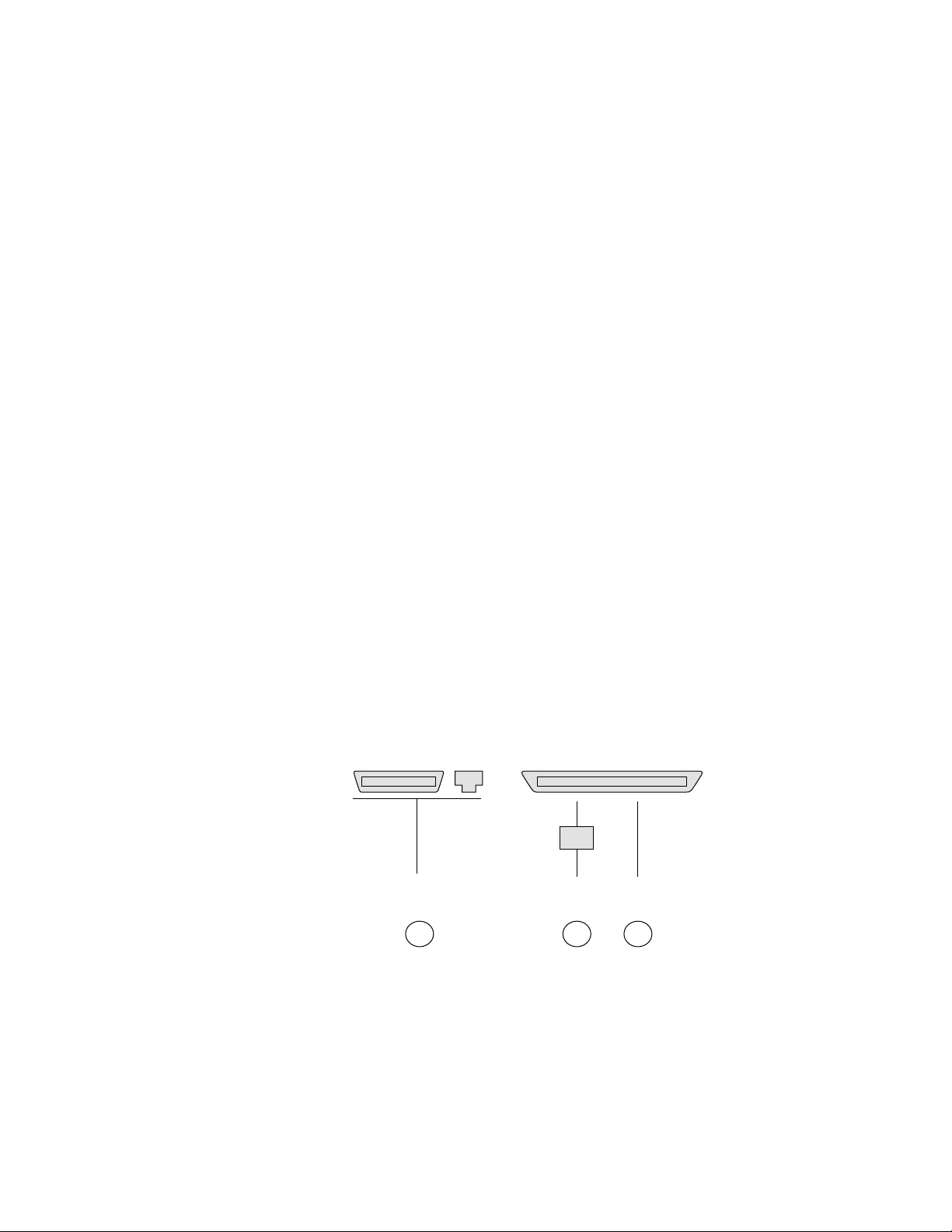
The following figure and table show possible methods for connecting HP
printers to various platforms. (Some printer interfaces are optional or available on a restricted range of HP models).
Printer:
Computer:
Ethernet
(LPR/JetDirect protocol)
Key:
JD JetDirect Unit
Parallel Ethernet
JD
Ethernet
B CA
Parallel
Figure 1.2 Printer connection methods
AG50324P3 Rev. 3
Page 13
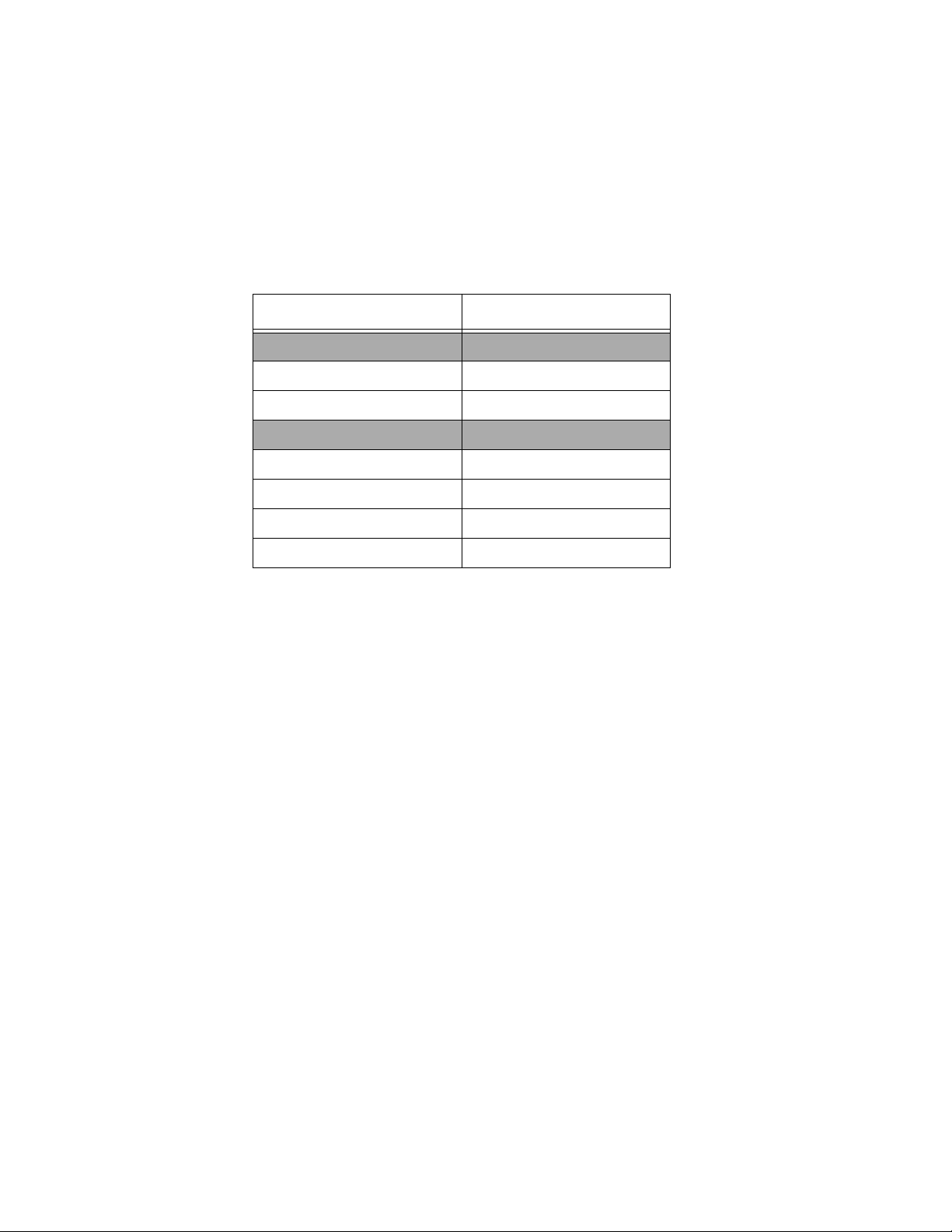
This table shows which of the methods, A through C, are supported by the
platforms on which the output plugin is available.
Platform HP DesignJet 5000 series
Macintosh
PowerPC pre G3 A, B
G3/G4/iMac A, B
Pentium PC
Windows ME A, B, C
Windows 98 A, B, C
Windows NT A, B, C
Windows 2000 A, B, C
1.4 Getting started
If you are connecting to the printer using a parallel printer port then in the
BIOS setup of your PC ensure the parallel port is set to use a bidirectional
mode. The way to enter and change the BIOS configuration varies from
machine to machine, as does the terminology used for bidirectional parallel
port modes. Refer to your PC manual for details. If you have any problems
using the parallel port, refer to page 52 and page 56 of the “Troubleshooting
and tips” section.
1.4 Getting started
Before you can output to a device you must enable the use of HIPP or
ColorPro, as well as the device. If you wish to use the 6-color mode of printing
you must also enable HDS.
If you have installed your plugin into version 5.3r1 or later of the RIP and you
have been supplied with a password file or password files, copy the password
file(s) into the
RIP, all device types for the enabled printers will be available for selection in
the Page Setup dialog box. You can then create a page setup, as described on
page 11. In some cases you may need or wish to create device types. See “Creating device types” on page 11 for details.
Passwords folder within the SW folder. When you next start the
AG50324P3 Rev. 3 9
Page 14

1 ProofReady Plugin for 6-Color HP Printers
If you have installed the plugin into earlier versions of the RIP, or you have
not been supplied with password files, you must enable the devices and color
management by following the steps in “Entering passwords”.
1.4.1 Entering passwords
The devices supported by the plugin are classed into series and you need just
one password to enable all the devices in a series. For example, a single password for the HP DesignJet 5000 Series enables all the printers in this series,
including the 42" and 62" inch wide models.
Follow the steps below to enable color management and devices.
If you wish to output in the 6-color mode, you must enable the use of HDS or
HDS light.
1. Enable the use of HDS or HDS Light by entering the password in the
Enable Feature dialog box.
Use the
Choose
box. Click
word and click
Harlequin RIP > Configure RIP menu option and click Extras.
HDS or HDS light from the list in the Configure RIP Extras dialog
Add to display the Enable Feature dialog box. Enter the pass-
OK.
2. Enable your chosen device(s).
For example, to enable all the devices in the HP DesignJet 5000 series,
choose the entry
Enable Feature dialog box, and enter the password. Click
HP, DesignJet 5000 Series, click Add to display the
OK.
3. Enable the use of HIPP or Harlequin ColorPro (Eclipse Release or later
RIPs) as described in step 1. Click
OK twice to exit the Configure RIP
dialog box.
4. If you have a problem with passwords, see “Problems with passwords”
on page 57.
Each device has multiple device types, which specify the use of different features such as roll-fed or sheet-fed media handling. The first time you enter a
password for a series of HP printers, the RIP and the plugin should make
available all supported device types in the
Device menu in the Page Setup
dialog box. You can then create a page setup for a device type as described in
“Creating a page setup” on page 11.
10 AG50324P3 Rev. 3
Page 15

1.4 Getting started
For details on device types and how to create them, see “Creating device
types”.
1.4.2 Creating device types
The device type that you use determines: the size of the device you are using
(42" vs. 62" wide); the paper handling (roll vs. sheet); and the printing mode
(4-color vs. 6-color). For example, the device type
allows you to send output to the 42" wide model of HP DesignJet 5000, using
the 6-color printing mode and roll-fed paper handling. Similarly, the device
type
DJ5000 Contone 60 Sheet allows you to send output to the 60" wide
model of the HP DesignJet 5000, using the 4-color printing mode and sheetfed paper handling.
If the
Device menu in the Page Setup dialog box does not contain the device
you require, you must use the Device Manager to create such a device:
DJ5000 6-Col 42 Roll
1. Use the menu option
Harlequin RIP > Device Manager to open the Device
Manager.
2. Depending on your platform, choose either
the
Plugin menu and click New.
3. Choose the device type you require from the
Manager Edit dialog box and enter a name for the device in the
hp6col.i32 or hp6col from
Type menu in the Device
Name
text box.
Note: If you use the same text to name the new device as that used to
label the device type, you must match the use of lowercase and uppercase characters in the device type label. Otherwise an error will appear
when using a page setup with this device type, as described on page 48.
4. Click
OK. The device will be listed in the Device Manager and become
available for selection in the Page Setup dialog box.
You can then create a page setup using this device, as described on page 11.
1.4.3 Creating a page setup
Once your desired device types are available for selection in the Page Setup
dialog box, you can create a page setup for the device.
AG50324P3 Rev. 3 11
Page 16

1 ProofReady Plugin for 6-Color HP Printers
The way in which you create a page setup depends on the Harlequin RIP version that you are using. In the Eclipse Release or later of the Harlequin RIP,
instant color management is possible by simply selecting a ProofReady
profile. See Section 1.4.3.2 on page 15 for details.
In former RIPs, instant color management is possible by selecting a supplied
calibration profile that includes a default color setup. See Section 1.4.3.1 below
for details.
Note: In Eclipse Release or later RIPs, an extra level of control has also been
added to the configuration of ProofReady plugins.There are now three ways
in which the ProofReady plugin can be used in such RIPs:
• Users can use automatic color management by simply selecting a profile
from the
ProofReady menu and using default settings, as described in
Section 1.4.3.2 on page 15.
• Users can choose a
ProofReady profile and change the default settings
used by creating a new separations style and a new ’ProofReady’ color
setup and selecting them from the
Style and Color menus. This option
allows users to change settings, such as those for recombine and
overprinting, while using the default ProofReady profiles. See Section
1.7 on page 36 for further details.
• Users can create a ColorPro color setup, which allows them to configure
all the color management settings, including the input and output profiles used. Users must choose
(None) from the ProofReady menu to
enable the selection of a ColorPro color setup. See Section 1.8.3 on page
46 for further details.
1.4.3.1 Creating a page setup in pre Eclipse Release RIPs
To create a ProofReady page setup in versions of the Harlequin RIP prior to
the Eclipse Release, you need to select a supplied calibration profile that
includes a default color setup, as described in the procedure below.
12 AG50324P3 Rev. 3
Page 17
1.4 Getting started
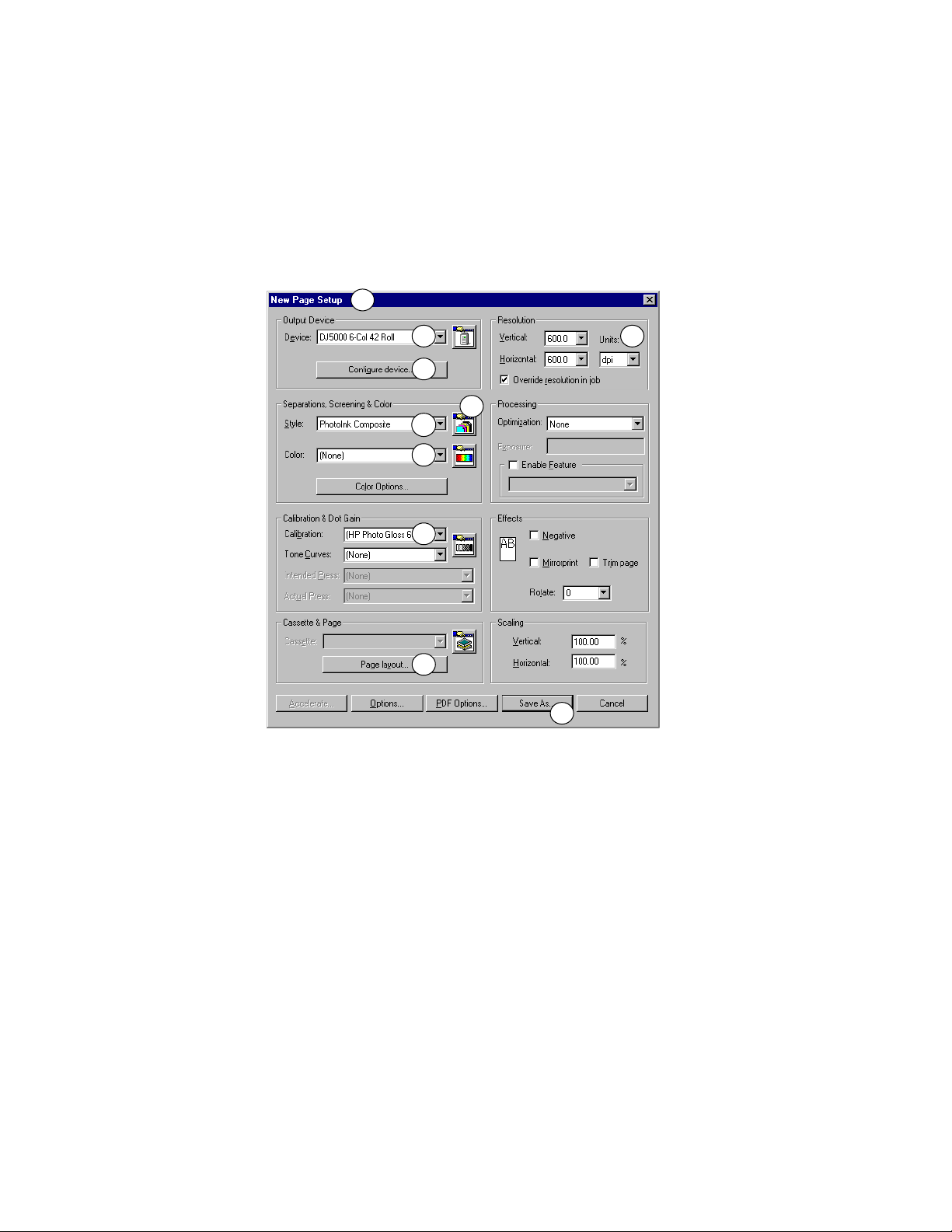
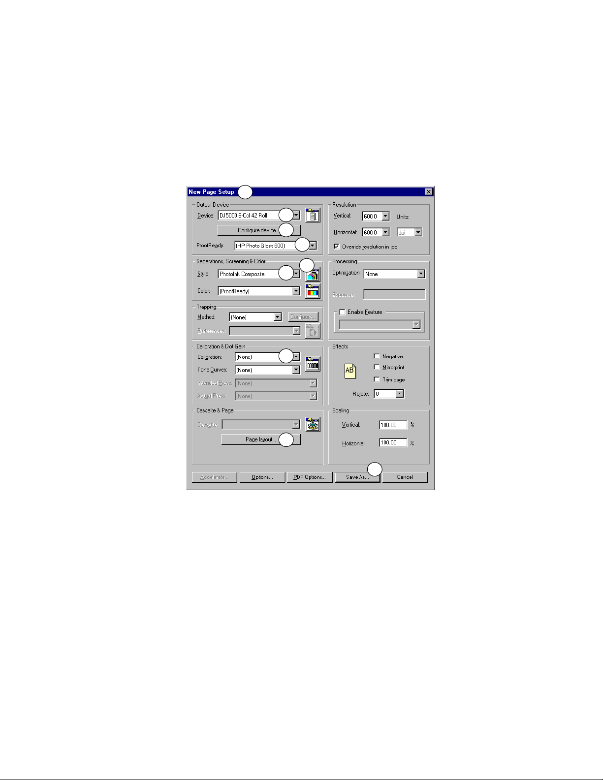
For each numbered step of the procedure the corresponding numbers in
Figure 1.3 highlight where choices are made in the New Page Setup dialog
box.
1
2 4
3
6
5
7
8
9
10
Figure 1.3 Creating a page setup in pre Eclipse Release RIPs
➀ Open the Page Setup Manager and click New.
➁ Choose the device required from the Device menu.
Note: If the device you require is not in the
device types” on page 11.
Device menu, see “Creating
➂ Click Configure device to modify configuration settings as desired. See
“Device configuration” on page 20 for details.
If using a supplied calibration profile choose the
Quality menu, because the supplied profiles were created using this
setting.
AG50324P3 Rev. 3 13
Best option from the
Page 18
1 ProofReady Plugin for 6-Color HP Printers
➃ Choose the desired resolution from the Vertical and Horizontal menus,
taking care to select the required units.
➄ Choose CMYK Composite from the Style menu if you are using a 4-color
device type or
PhotoInk Composite if using a 6-color device type.
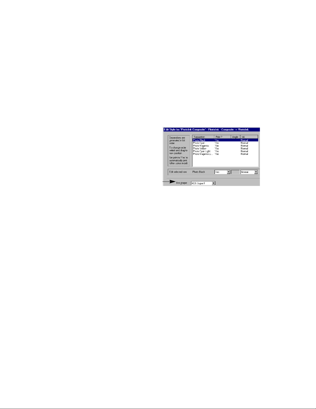
➅ If using a 6-color device type, check in the Edit Style dialog box that
screening is set to its default value of
To open the Edit Style dialog
box, click the Separations
Manager icon. Click
Separations Manager and check
the screening option in the
Dot shape menu. Click OK twice
to return to the Page Setup
dialog box.
➆ Choose (None) from the Color
menu.
HDS Super F.
Edit in the
Note: Selecting a calibration profile or calibration set includes a default
color setup. You can choose an option from the
to use a color setup that you have previously created. See “Creating a
HIPP or ColorPro color setup” on page 46 for details.
Color menu if you wish
➇ Choose a profile from the Calibration menu that matches the currently
selected ink/paper type and resolution (as specified in step
For example,
HP DesignJet Photo Gloss Paper based on a resolution of 600 x 600 dpi.
See “Supplied profiles” on page 18 for a full list of supplied calibration
profiles.
For optimum results you can choose a calibration set that has been generated for the actual printer rather than for a reference printer. See “Calibration” on page 40 for details.
14 AG50324P3 Rev. 3
(HP Photo Gloss 600) is a supplied calibration profile for
➃).
Page 19

1.4 Getting started
➈ Click Page Layout to specify the positioning of the page, using the
margin and centering controls.
Note: If you are using a sheet-fed device, you must refer to details on
how to control top and bottom margins provided in the Page Layout section on page 38.
➉ Click Save As and enter a page setup name in the Save As text box. Click
Save in the Save Setup dialog box and then OK in the Page Setup
Manager.
You can now use this page setup when printing to produce color managed
output.
1.4.3.2 Creating a page setup in Eclipse Release or later RIPs
To create a ProofReady page setup in the Eclipse Release or later of the
Harlequin RIP, you simply need to select a ProofReady profile, as described in
the procedure below.
AG50324P3 Rev. 3 15
Page 20
1 ProofReady Plugin for 6-Color HP Printers
For each numbered step of the procedure the corresponding numbers in
Figure 1.4 highlight where choices are made in the New Page Setup dialog
box.
1
2
3
4
6
5
7
8
9
Figure 1.4 Creating a page setup in Eclipse Release or later RIPs
➀ Open the Page Setup Manager and click New.
➁ Choose the device required from the Device menu.
Note: If the device you require is not in the
device types” on page 11.
Device menu, see “Creating
➂ Click Configure device to modify configuration settings as desired. See
“Device configuration” on page 20 for details.
16 AG50324P3 Rev. 3
Page 21

1.4 Getting started
If using a supplied profile choose the Best option from the Quality menu,
because the supplied profiles were created using this setting.
➃ Choose a profile from the ProofReady menu that matches the currently
selected ink/paper type. The correct resolution for the profile is automatically selected and should not be changed.
For example,
Gloss Paper based on a resolution of 600 x 600 dpi. See “Supplied profiles” on page 18 for a full list of ProofReady profiles.
Note: When you select a ProofReady profile, a default
color setup is selected in the
ProofReady menu if you wish to use a ColorPro color setup that you
have created, as described in Section 1.8.3 on page 46.
(HP Photo Gloss 600) is a profile for HP DesignJet Photo
(ProofReady)
Color menu. Choose (None) from the
➄ Choose CMYK Composite from the Style menu if you are using a 4-color
device type or
PhotoInk Composite if using a 6-color device type.
➅ If using a 6-color device type, check in the Edit Style dialog box that
screening is set to its default value of
To open the Edit Style dialog
box, click the Separations
Manager icon. Click
Separations Manager and check
the screening option in the
Dot shape menu. Click OK twice
to return to the Page Setup
dialog box.
Edit in the
HDS Super F.
➆ Choose (None) from the
Calibration menu.
Note: Selecting a
profile. For optimum results you can choose a calibration set that has
been generated for the actual printer rather than for a reference printer.
See “Calibration” on page 40 for details.
AG50324P3 Rev. 3 17
ProofReady profile includes a default calibration
Page 22

1 ProofReady Plugin for 6-Color HP Printers
➇ Click Page Layout to specify the positioning of the page, using the
margin and centering controls.
Note: If you are using a sheet-fed device, you must refer to details on
how to control top and bottom margins provided in the Page Layout section on page 38.
➈ Click Save As and enter a page setup name in the Save As text box. Click
Save in the Save Setup dialog box and then OK in the Page Setup
Manager.
You can now use this page setup when printing to produce color managed
output.
1.5 Supplied profiles
The following table lists the paper types for which calibration and color profiles have been provided. The profiles
600 x 600 dpi. Y ou can use the profiles to output in both the 4-color and 6-color
modes for selected paper types.
are available for a resolution of
If you need to use the printer in another configuration, you must obtain your
own calibration and color profiles.
The name of the profile appearing in the Harlequin RIP is the text that appears
in code format in the
Paper T ype column followed by the r esolution, all enclosed
in parentheses. For example, a profile for HP DesignJet Photo Gloss Paper at
600 x 600 dpi is
Heavyweight Coated Paper
HP Heavy Coated
Photo Gloss Paper
HP Photo Gloss
18 AG50324P3 Rev. 3
(HP Photo Gloss 600)
Paper Type Part Number HP 5000 series
C6030B •
C6963A •
Page 23

1.5 Supplied profiles
1.5.1 Halftone screen selection
The supplied profiles have been generated for use with HDS Super Fine
screening (6-color mode) and the default screening for the device (4-color
mode). Alternative screen sets are available but they may produce poor color
output if used in conjunction with the supplied profiles.
For color output, there are supplied profiles for:
HDS Super Fine
This is the screen set used to produce the supplied profiles for use with 6-color device types. If using a supplied profile based on this screen, ensure that this
option is selected from the Edit Style dialog box
accessed from the Separations Manager.
Device Default Screening
This is the screening used for 4-color (Contone) device
types. All the profiles for the 4-color device types were
created using this screening. This screening is automatically selected when you use a 4-color device type.
For color output without supplied profiles the following screen sets are available when using a 6-color device type:
HDS Fine This is an alternative to HDS Super Fine, producing a
coarser screen than HDS Super Fine.
HDS Medium
HDS Coarse
HDS Super Coarse
The Medium, Coarse, and Super Coarse variants of
HDS are only recommended as special effects screens.
Round This is the default screening used by 6-color device
types if you enable the device before you enable the use
of HDS. See “Entering passwords” on page 10 for
details.
AG50324P3 Rev. 3 19
Page 24

1 ProofReady Plugin for 6-Color HP Printers
Refer to the Harlequin RIP OEM Manual for further details of screens supplied
with the RIP.
1.6 Device configuration
Figure 1.5 Configure Device dialog box
Output Method
The options that appear in this menu are the various methods of connecting the output plugin to the physical printer , together with the print
to file option. If you choose
address and port number in this dialog. If you choose
Network you must specify the correct IP
File you must
specify a valid location to produce the file, as well as a valid file name
template.
For Windows platforms, the standard options are:
LPT1: (parallel). If your computer is equipped with a USB port, you may
have an extra entry, such as
USB Root Hub. This entry is not an appropri-
Network, File, and
ate choice for connecting to a printer; do not select it.
For Macintosh computers, the standard options are:
File Output: Change...
Network and File.
The text box alongside this button shows the location where the plugin
will produce the output file.
20 AG50324P3 Rev. 3
Page 25

The initial target folder is the SW folder, which is a subfolder of the RIP
application folder. Click the
Change... button to display the Select Folder
dialog box where you can navigate to and select any folder visible to the
computer running the RIP. If you wish to create a new target folder,
navigate to where the folder will be created and click
name of your new target folder and then click
OK. Alternatively, on
New. Enter the
Windows only, you can edit the text if you know the exact location of an
existing folder.
Note: You can send files to a printer using Windows print spooling by
installing Windows printer drivers on a PC print server, and by entering
the name of the print server in this text box. See “Sending files to a printer
using Windows printer drivers” on page 58 for full details.
File Output: File Template
The text box alongside this button shows the file name template used to
name an output file.
1.6 Device configuration
The default file name template is
<dos>out<5unique><dot>hpf. This tem-
plate produces a file name that is cross platform (8.3 file name) and suitable for multi-page jobs. It produces file names of the form:
out00001.hpf, out00002.hpf, and so on. The file produced is suitable for
sending directly to the printer.
See “Output file naming” on page 25 for details on creating a file name
template.
Note: You can send files to a printer using Windows print spooling by
installing Windows printer drivers on a PC print server, and by entering
the name of the printer in this text box. See “Sending files to a printer
using Windows printer drivers” on page 58 for full details.
Network Output: IP Address
This text box shows the network address of the print server. This
address is a configurable property of a JetDirect unit or similar device.
Enter the network address of the print server that you are using. If your
network supports the use of names, you can enter a name and this will
be resolved to the IP address.
AG50324P3 Rev. 3 21
Page 26

1 ProofReady Plugin for 6-Color HP Printers
Network Output: Port Number
The text box alongside this button shows the number of the port you
wish to use. The available port numbers depend on the type of print
server that you are using. If your printer has an internal JetDirect print
server you can set the
whether you wish to communicate with the printer using the LPR (
or JetDirect (
9100) protocol.
Note: The LPR protocol does not provide bidirectional communication
with the printer. Consequently the printer cannot report error messages
when using this protocol. Use the port number
Port Number to either 515 or 9100, depending on
515)
9100 to avoid this.
If you are using an external JetDirect print server you must set the
Number
to 9100, or a similar number.
Some external print servers can drive several printers simultaneously. In
this case the different physical connections or ports have their own numbers (which may vary with the type of server). For example, on an external JetDirect unit with three output ports, the physical ports named 1, 2,
and 3 have port numbers
9100, 9101, and 9102.
The RIP supports the use of another printer connected to the same print
server. For example, two computers running the RIP and driving the
same print server can address any compatible printer connected to that
server.
Output: Paper Size
The options that appear in this menu are the sizes of paper supported by
the plugin and the printer , as well as the option to cr eate a custom paper
size. The dimensions for the standard paper sizes are listed in Table 1.1
below.
You can create a custom paper size by selecting the
"Page Layout"
option from this menu and specifying the dimensions of
Media size from
the paper size in the Page Layout dialog box. To open this dialog box,
Page layout in the Cassette & Page section of the Page Setup dialog
click
box. Enter dimensions for the paper in the
Media Length (ML) text boxes. If using a roll device, the Media Length (ML)
Media Width (MW) and
text box is grayed out. Note that clipping may occur if you change the
Port
22 AG50324P3 Rev. 3
Page 27

1.6 Device configuration
paper size in a page setup that used a custom paper size. See page 49 for
full details.
You can control the positioning of the imaged job on the media by using
the controls in the Page Layout dialog box. See page 38 for details.
Paper Size
Banner 8.5 x 44 215.9 x 1117.6
A2 16.54 x 23.39 420 x 594
US-C 17 x 22 431.8 x 558.8
B2 20.28 x 28.66 515 x 728
US-D 22 x 34 558.8 x 863.6
A1 23.39 x 33.11 594 x 841
B1 28.66 x 40.55 728 x 1030
A0 33.11 x 46.81 841 x 1189
US-E 34 x 44 863.6 x 1117.6
Super A0 35.98 x 50.87 914 x 1292
B0 40.55 x 57.32 1030 x 1456
Super B0 44.02 x 62.20 1118 x 1580
Architectural C 18 x 24 457.4 x 609.6
Architectural D 24 x 36 609.6 x 914.4
Dimensions
(inches)
Dimensions (mm)
Architectural E 36 x 48 914.4 x 1219.4
Architectural E1 30 x 42 762.0 x 1066.8
24" Roll 24 (wide) 610
36" Roll 36 (wide) 914
42" Roll 42 (wide) 1066.8
44" Roll
44(wide) 1118
Table 1.1 Paper size names and dimensions
AG50324P3 Rev. 3 23
Page 28

1 ProofReady Plugin for 6-Color HP Printers
Paper Size
54" Roll 54 (wide) 1371.6
60" Roll 60 (wide) 1524
Table 1.1 Paper size names and dimensions
Output: Quality
Dimensions
(inches)
Dimensions (mm)
The options in this menu are only available when using the 4-color
printing mode (Contone) because the 6-color mode always uses the
option.
The options are methods of driving the printer, which offer combinations of speed and image quality that may depend on the printer’s
capabilities. Refer to your printer documentation for details of the relative merits of these quality settings.
If you are using supplied calibration profiles it is recommended that you
use the
The
Best option.
Printer Default option uses the quality setting specified in the con-
trol panel on the printer.
Best
Output: Compression mode
The options that appear in this menu are methods of coding the data
sent to the printer. The coding methods can affect the time taken to
transfer data to the printer.
None sends the data uncompressed.
Run-Length Encoding performs a lossless compression that enables the
exact data to be recreated. For many images, using
Run-Length Encoding
will reduce the size of the data and the time taken to transmit it. For
some very complex pages containing large areas of fine detail, it may
take longer to send a page coded with
the same page coded with
TIFF (Packbits) Encoding is a variant of run-length encoding, which
None.
Run-Length Encoding than to send
also performs a lossless compression but with a higher compression
24 AG50324P3 Rev. 3
Page 29

ratio. This mode therefore allows a more efficient transfer of data than
run-length encoding. This mode is the default selection.
Output: Cut paper at end of each page
If you are using a roll-fed device, you can select this check box to instruct
the printer to cut paper at the end of each page. You must also ensure
that the cutter is enabled on your printer.
Output: Post Processing
You can enter commands in this field to perform actions once the page
buffer has been sent to the printer or once the output file has been
created. For example, you may wish to change the format of the output
file or generate a report. For full details see “Post processing” on
page 33.
Note: The plugin does not support post processing on Macintosh
computers.
1.6 Device configuration
1.6.1 Output file naming
The File Template text box within the Configuration dialog box enables you to
specify the automatic generation of an output file name using a template of
fixed text and tags.
Most tags are content tags, representing variables such as the date and time a
job is processed; the other tags allow you to reject names that would be illegal
in a specified operating system. The maximum length of variables can be
specified by preceding the tag name with an integer. For example,
truncates the job name to a maximum of five characters. Tags that produce
numeric values are truncated from left to right, whereas tags that produce
alphanumeric strings (strings containing the characters a-z, A-Z, and 0-9) are
truncated from right to left. See “Examples of tag usage” on page 28 for further details.
Fixed text can be part of the file name stem or extension. For example,
stem_<3unique><sepname><dot>hpf would generate a file name of the form:
stem_000Cyan.hpf, in which stem_ can be any identifying text.
<5jobname>
AG50324P3 Rev. 3 25
Page 30

1 ProofReady Plugin for 6-Color HP Printers
Try to use a file name extension that does not clash with any established
convention. The extension
tial letters of HP Printer File
Note: This file naming scheme does not provide useful file names derived
from job names that contain double-byte characters.
1.6.1.1 Content generating tags
The following tags are available and can be used in any order:
Tag Description
hpf is a suggestion only and is formed from the ini-
.
<colorant> The color space of the device, such as DeviceCMYK or
<colorname>
<compression>
<date>
<dot>
<exposure>
<job#>
<jobname>
<jobname1>
<page#>
DeviceRGB
The name of the separation, such as Cyan.
The form of compression used, such as TIFF (Packbits).
The date when the job is processed, in the format YYYYMMDD, unless a
truncated form is specified.
Separates the stem of the file name from the file extension, and
appears as a period character ( . ) in the file name. For example
stem<dot>ext
enables the verification of the stem and extension lengths.
The exposure setting, a device specific integer.
The job number allocated by the RIP. Automatic numbering means that
successive jobs have incremented job numbers: 000, 001, 002, 003,
and so on.
The page buffer name without the page number prefix and without
characters illegal to the operating system. White space characters are
used, if present in the job name.
The page buffer name without the page number prefix, and using only
alphanumeric characters (a-z, A-Z, 0-9). White space characters are
not used.
The page number (allocated by the RIP), within the current job. For
example: 002.
.
appears as stem.ext. The use of the <dot> tag
<prefix>
The page number prefix from the page buffer name, such as 1., 2.,
and so on.
Table 1.2 Output file name tags
26 AG50324P3 Rev. 3
Page 31

Tag Description
<quality> The quality setting, such as Fast.
1.6 Device configuration
<time>
<unique> A unique sequence number used to make every file different when
<xres>
<yres>
The time when the job is processed, in the 24-hour format HHMMSS,
unless a truncated form is specified.
placing output files in a folder.
The horizontal resolution of the page, as specified in the page setup.
The vertical resolution of the page, as specified in the page setup.
Table 1.2 Output file name tags
1.6.1.2 Checking tags
The plugin always checks the legality of an automatically generated file name
against the requirements of the operating system on which the RIP and the
plugin are running.
To enable portability of files from one operating system to another, you can
also use tags to specify the operating system for which generated file names
must be suitable. The use of these tags changes the rules by which a file name
is deemed valid. The tags do not modify the file names generated, but cause
error messages if the file name is invalid. See “Messages for file name templates” on page 53 for details.
For example, you can create the template
<dos>Averylongfilename<dot>hpf,
but an error is generated. This error occurs because DOS file names require
the 8.3 format for stem and extension, which this template fails to meet by
having 17 characters in its stem. Table 1.3 lists the operating system tags.
Tag Description
<dos>
<mac>
AG50324P3 Rev. 3 27
Verifies that the file name is a legal file name for the MS-DOS operating
system.
Verifies that the file name is a legal file name for the Macintosh operating
system.
Table 1.3 Operating system tags
Page 32

1 ProofReady Plugin for 6-Color HP Printers
Tag Description
<unix>
<win32>
Verifies that the file name is a legal file name for the UNIX operating
system.
Verifies that the file name is a legal file name for Windows operating
systems: Windows 95, Windows 98, Windows NT, or Windows 2000.
Table 1.3 Operating system tags
1.6.1.3 Examples of tag usage
The following examples demonstrate the format of strings produced by individual tags. Some examples also show how the tags may be used in combination to form a template. The examples are based on these job details:
Page buffer name: 1. Uncalibrated Target: Default CMYK + spot colors target
Date: 12th of August, 2000
Exposure: 110
Compression: TIFF(Packbits) Encoding
Quality: Best
Note: When creating multiple copies of a file, the same page buffer provides
tag information. If a template contains dynamic tags (such as
the value changes each time a page buffer file is output), multiple copies of the
file are created. If the template contains just static tags (such as
where the job name remains constant), a single output file is created because
previous files are overwritten.
<time>, where
<jobname>,
<colorant>
This tag includes the color space of the device in the file name string.
For example, the template
the form
DeviceCMYK.hpf for a device using a CMYK color space (4-
colors) or a file name of the form
<colorant><dot>hpf produces a file name of
PhotoInk.epf for a device using a Pho-
toInk color space (6-colors).
28 AG50324P3 Rev. 3
Page 33

<colorname>
The tag <colorname> can be used to include the name of the separation in
a file name, for example
separation by using the tag
Cyan. You can include just the first letter of the
<1colorname>, which truncates the separation
name to its first letter . If a composite style is used this is indicated by the
string
<compression>
Composite.
You can use this tag to include the form of compression used in the file
name. For example, based on the job details above, the template
<compression><dot>hpf produces the file name TIFF (Packbits).hpf.
<date>
The template <date><dot>hpf produces the file name 20000812.hpf. You
can remove the year information by using the tag
the file name
<dos>
0812.hpf.
<4date> to produce
1.6 Device configuration
The use of this tag verifies that the file name is suitable for use in a DOS
operating system. Illegal characters such as a colon, and white space
characters cause an error.
For example, the template
<dos><jobname><dot>hpf, would generate an
illegal file name because the job name is greater than the eight characters
allowed in DOS operating systems. Truncation can be forced by using
the template
Uncalibr.hpf.
<dot>
<dos><8jobname><dot>hpf, which produces the file name
This tag separates the file name stem from the file name extension and
enables the verification of their lengths. It is particularly necessary when
creating file names compatible with DOS and Windows, otherwise the
extension may be considered as part of the file name.
For example, the template
because the dot is removed as an illegal character and
<dos><8jobname>.hpf would cause an error
hpf is then consid-
ered part of the file name stem.
AG50324P3 Rev. 3 29
Page 34

1 ProofReady Plugin for 6-Color HP Printers
<exposure>
You can use this tag to include the exposure setting of a page in the file
name.
For example, based on the job details above, the template
<exposure><dot>hpf produces the file name 110.hpf.
<job#>
You can use this tag to include the job number in the file name string.
The default length of the number is three digits, so the first job number
created with this tag would be 000, unless a different length is specified.
Y ou can specify the length of the job number by pr eceding the
with an integer. For example, <
long.
<job#> tag
5job#> creates job numbers five digits
In multi-page jobs use the
<page#> tag as well as the <job#> tag to differ-
entiate between the different pages of a job.
<jobname>
This tag ensures that only legal operating system characters are used in
the job name.
For example, in the RIP running under any Windows operating system,
the template
Uncalibrated Target Default CMYK + spot colors target.hpf. The
colon character (
<jobname><dot>hpf produces the file name
: ) is removed from the file name, because this is not a
valid file name character for any version of Microsoft Windows.
<jobname1>
This tag ensures that only alphanumeric characters are used in the job
name.
For example, in the RIP running under a W indows operating system, the
template
UncalibratedTargetDefaultCMYKspotcolorstarget.hpf. The colon, white
<jobname1><dot>hpf produces the file name
space, and ‘+’ characters are removed from the file name, because they
are not alphanumeric characters.
30 AG50324P3 Rev. 3
Page 35

<mac>
The use of this tag verifies that the file name is suitable for use in a
Macintosh operating system. Illegal characters such as an asterisk, colon,
and quotation marks cause an error. The maximum length of a file name
is thirty-one characters (including the file extension).
1.6 Device configuration
For example, using the template
file name
Uncalibrated Target Default.hpf, in which the colon has been
<mac><28jobname><dot>hpf produces the
removed.
<page#>
You can use this tag to include the page number in the file name string.
For example, the template
form
001.hpf. It is advisable to use this tag with the <job#> tag to differ-
<page#><dot>hpf produces a file name of the
entiate between the same pages of different jobs.
<prefix>
You can use this tag to include the page number prefix from the page
buffer name in the file name string.
For example, based on the page buffer name above, the template
<prefix><jobname><dot>hpf produces the file name 1. Uncalibrated
Target Default CMYK + spot colors target.hpf
<quality>
.
You can use this tag to include the quality setting in the file name string.
For example, based on the job details above, the template
<quality><dot>hpf produces the file name Best.hpf.
<time>
You can use this tag to include the time a file is processed in the file
name string.
For example, if printing to file at 15:39:36 (approximately 3:39 pm) this
tag produces the string
<unique>
153936.
You can use this tag to generate a unique sequence number for the page.
The default length of the number generated is four digits long, so the
AG50324P3 Rev. 3 31
Page 36

1 ProofReady Plugin for 6-Color HP Printers
first number would be 0000. The length of the number can be specified,
as detailed in the example for the tag
When restarting the RIP, the unique numbering will attempt to restart at
its initial value, for example
ber, the next available unique number is used.
<unix>
The use of this tag verifies that the file name is suitable for use in the
UNIX operating system. Illegal characters such as an asterisk, colon, and
quotation marks cause an error. The
tag because file names in UNIX are composed of a single string and are
not considered to have separate file extensions.
<job#>.
0000. However , if a file exists with that num-
<dot> tag cannot be used with this
For example, using the template
file name
UncalibratedTargetDefaultCMYK+spotcolorstarget.hpf, in
<unix><255jobname>.hpf produces the
which the colon and white space characters have been removed.
<win32>
The use of this tag verifies that the file name is suitable for use in a
Windows operating system. Illegal characters such as an asterisk, colon,
or quotation marks cause an error.
For example, the template
name
Uncalibrated Target Default CMYK + spot colors target.hpf, in
<win32><jobname><dot>hpf produces the file
which the colon has been removed.
<xres>
You can use this tag to include the horizontal resolution of the page in
the file name string.
For example, you can differentiate between pages with a resolution of
600 x 600 dpi and 300 x 300 dpi by using this tag. This tag produces a
string such as
<yres>
600 or 300, depending on the horizontal resolution.
You can use this tag to include the vertical resolution of the page in the
file name string. For example, on a page with the resolution 600 x 600,
this tag produces the string
600.
32 AG50324P3 Rev. 3
Page 37

1.6 Device configuration
1.6.2 Post processing
The Configuration dialog box has an Output: Post Processing text box in which
you can enter commands and their options, in the same way as a command
line. These commands are carried out after the page buffer has been sent to the
printer or once the output file has been created. The commands available
depend on the platform on which you are running the RIP.
Note: You cannot perform post processing if you are using a Macintosh
computer.
The command can be a simple batch file or a complex application, provided
that you give the command all necessary options and information; a command needing operator intervention is likely to cause problems. You can specify options understood by the application, and data such as the path of the
relevant input or output files.
Y ou can use post pr ocessing commands to convert the file to a differ ent format
or to send somebody an e-mail notifying them that a job has been processed.
There are several other possibilities, such as extracting information for use in
reports, limited only by your ability to obtain or create a suitable application
and to supply information to it.
If the string you enter into the
Output: Post Processing text box refers to a post
processing application then this application must be available on the computer running the RIP. The string should normally include the file extension
and the full path name of the application file. However, you can type just the
file name if the application file has the extension
directories specified by the
PATH variable.
.EXE and is in one of the
Your string can contain substitution codes, which are expanded by the RIP.
See “Post processing substitution codes” for details.
AG50324P3 Rev. 3 33
Page 38

1 ProofReady Plugin for 6-Color HP Printers
1.6.2.1 Post processing substitution codes
When using the post processing feature of the HP plugin, the RIP recognizes
the substitution codes in the following list. You can insert an integer between
the percent character and the letter code, to restrict the maximum number of
characters used in the result string. For example,
characters of the job name.
%6j represents the first six
Post processing
substitution codes
%c The current separation color, represented by a string with a default
%d The current date in the format YYYYMMDD, with a default string
%e The job exposure, as entered in the Page Setup dialog box. For
%f The output file name, as created by the template specified in the
length of one character. Typical separation names are Cyan,
Magenta
C, Y, M, and B.
length of 8. For example, 26 October 2000 becomes: 20001026.
example:
, Yellow and Black. Examples for the default length are:
221.
Description
File
Output: File Template text bo x in the Configur ation dialog bo x. For
example: out00001.hpf.
%j The current page buffer name as shown in the Output
%n The current job number, an integer that the RIP increments each
%o The full output directory path specified in the
Controller/Monitor. For example:
time it processes a new job. For example:
1. Apple.ps.
15.
File Output:
Change... text box. For example: C:\SWNT\SW\Output\.
%p The current page number within the job. For example:
%r The job resolution in dots per inch. For example:
4.
300.
%s The current job name, after removal of all the characters that would
%t The current time in the format HHMMSS, using the 24 hour clock.
%x The current file name suffix. For example:
be illegal in a file name. For example:
The default length is 6. For example, a time just after 7:30 pm would
be shown:
193211.
Appleps.
hpf.
Table 1.4 Post processing substitution codes
34 AG50324P3 Rev. 3
Page 39

1.6 Device configuration
Post processing
substitution codes
%z The current file name stem. For example: out00001.
Table 1.4 Post processing substitution codes
Description
1.6.2.2 Checking the command string
The RIP reports each command and the working directory in the main RIP
monitor window, in the following form. Italics show which text can vary with
different jobs and page setups.
Running post-job command "C:\test\logfile.bat out00002.hpf 112442" in
directory C:\SWNT\SW\Output
The above example refers to a batch file (logfile.bat) which uses a program
to send an e-mail confirming that a job has been processed. The e-mail contains the job name (
(approximately 11:24). These details were provided by using the substitution
codes
%f and %t in the post processing text box. The working directory is the
output file folder specified in the
file folder is specified then the working directory is the ‘
which is one level below the directory containing the RIP executable.
out00002.hpf) and the time it was processed
File Output: Change... text box. If no output
..\SW\’ directory,
For a more thorough test of how commands behave when used at the command prompt of the operating system, try creating a batch (
.BAT) file with
these contents and using the name of the batch file as the application in your
command string.
echo %1 %2 %3 %4 %5 %6 %7 %9
pause
Note: If you have problems with a command, test it outside the RIP by opening a command window and running the command manually. If you think
that you have used any substitution code from which the RIP might generate
an element containing characters with a special meaning to your operating
system, try surrounding that code with double quotes. For example, use
in the post processing text box rather than just
AG50324P3 Rev. 3 35
%f.
"%f"
Page 40

1 ProofReady Plugin for 6-Color HP Printers
If there are no special characters involved, look at the number of substitution
codes that you are using and the length of the command string both before
and after expansion of the substitution codes. The limit on the length of the
expanded command string varies with the Microsoft Windows environment
but you should have no problems with up to 125 characters in the string after
expansion.
1.7 Routine use
To send output to a device or file you must create a page setup. This involves
two main steps. Firstly, you must choose your device from the
the Page Setup dialog box and configure the device as described in “Device
configuration” on page 20. Secondly, you must set the desired page setup
options to complete a page setup.
1.7.1 Page setup controls
Device menu in
The page setup controls that you generally need to consider are described
below. See the Harlequin RIP OEM Manual for further details.
Device
Device menu offers a list of supported device types.
The
If the device type that you require is not available in this menu, see
“Creating device types” on page 11.
ProofReady
This menu appears in Eclipse Release or later RIPs. You can choose a
ProofReady profile from this menu which uses a color setup and calibration profile for a particular paper, ink and resolution combination. See
“Supplied profiles” on page 18 for further details.
When you select a profile from this menu, the correct resolution is automatically set and should not be changed. A default
(ProofReady) color
setup is also used. If you wish to use a color setup that you have created,
choose
(None) from this menu. See “Creating a HIPP or ColorPro color
setup” on page 46 for details on how to create your own color setup.
36 AG50324P3 Rev. 3
Page 41

Style
By default, there is only one option in the Style menu in the Separations,
Screening & Color
using a 4-color (Contone) device type;
section of the Page Setup dialog box: CYMK Composite if
PhotoInk Composite if using a 6-
color device type.
You can create other styles using the Separations Manager. Refer to the
Harlequin RIP OEM Manual for details.
Color
In versions of the Harlequin RIP prior to the Eclipse Release, the selection of a supplied calibration profile, or a calibration set created on the
basis of a supplied profile, includes a default color setup. Set
(None) if you wish to use the default color setup. You can use the sup-
plied color profiles to create your own color setup, as described in Section 1.8.3 on page 46. Section 1.8.2 on page 44 describes the production
and installation of your own profiles, which you can then use to create a
color setup.
1.7 Routine use
Color to
In the Eclipse Release or later of the Harlequin RIP, the selection of a profile from the
ProofReady menu includes a default (ProofReady) color
setup. You can use the supplied color profiles to create your own color
setup, as described in Section 1.8.3 on page 46. To use your own color
setup, you must choose
You can also create a
ProofReady profile but modify some of the default settings, such as those
for overprinting. To create a
Color Setup Manager with a
the same as those for a
(None) from the ProofReady menu.
New ’ProofReady’ Setup if you wish to use a
New ’ProofReady’ Setup you must access the
ProofReady profile selected. The options ar e
New ’No Color Management’ Setup, as described in
the Harlequin RIP OEM Manual.
Resolution
The Horizontal and Vertical menus offer a list of the resolutions supported
by the printer. Choose resolutions that satisfy your desire for speed of
output (lower resolution) or quality (higher resolution).
Note: If you use profile based on a specific resolution, ensure the resolution matches.
AG50324P3 Rev. 3 37
Page 42

1 ProofReady Plugin for 6-Color HP Printers
Calibration
You can select a calibration profile or calibration set from the
list in the
Calibration & Dot Gain section (See Section 1.5 on page 18 for
details of the supplied calibration profiles.)
In versions of the RIP prior to the Eclipse Release, the selection of a cali-
bration profile or calibration set includes a default color setup, unless
you choose an alternative from the
Color menu. Note that if you choose
an alternative color setup, ensure that it is suitable for the paper type,
ink and resolution.
In the Eclipse Release or later of the Harlequin RIP, the selection of a profile from the
Calibration to (None) if you wish to use the default calibration profile. For
ProofReady menu includes a default calibration profile. Set
optimum results you can choose a calibration set that has been generated for the actual printer rather than for a reference printer. See “Calibration” on page 40 for details.
Page Layout
The margins and centering options control where the imaged job
appears on the media. There is a small unimageable margin around the
edge of the media, which varies according to the printer model. Refer to
your printer documentation for details. The positioning of the job is also
different for roll and sheet-fed devices.
Calibration
Roll-fed When the device is roll-fed, the page defined by the job
is located at the top-left of the sheet, unless you set a
non-zero
Width
(TM)
Bottom Margin (BM) on a roll-fed device this adds space
Left Margin or select the Center page on Media
check box. You can also set both the Top Margin
and the Bottom Margin (BM). If you increase the
to the bottom of the page.
Sheet-fed When the device is sheet-fed, the origin of the page
defined by the job is located at the bottom-left of the
sheet. However, in the Page Layout dialog box of some
versions of the RIP, only the
with a default value of
38 AG50324P3 Rev. 3
Top Margin (TM) is editable
0.00 inches. If these default set-
Page 43

tings were applied the job would be located at the topleft of the sheet. To prevent this, the
applied as the
Bottom Margin (BM). If your version of the
Top Margin (TM) is
RIP needs to swap these values a message confirming
this is displayed in the RIP monitor window.
1.7 Routine use
If you increase the
Bottom Margin (BM) on a sheet-fed
device, space cannot be added to the bottom of the
page. This means that the space available on the sheet is
reduced.
The
Page size represents the frame within which text and images are
printed. Whereas
Paper Size, specified in the Configure Device dialog
box, is the size of the medium printed on. In order to print unclipped
pages the page size must not exceed the paper size. Because the
Size
is specified in the Configure Device dialog box, you do not need to
specify the
Media Width or Media Length, unless creating a custom paper
Paper
size.
Note: The
Page size that you can choose here is only important if you
print a job that does not specify its own page size. Such jobs are rare, but
include EPS files and the job created by the menu option
Fonts
.
Fonts > Proof
Make all other settings as normal, following the suggestions in the Harlequin
RIP OEM Manual.
1.7.2 Roaming page buffers
You can view page buffers on screen using the standard RIP tools, but some
things are potentially confusing when you are viewing PhotoInk page buffers
created using 6-color device types:
• The title bar of the Roam window displays asterisk (
* ) characters,
where you might expect to see letters representing the colors in the page
buffers. This is normal when the color system is not Gray, RGB, or
CMYK.
AG50324P3 Rev. 3 39
Page 44

1 ProofReady Plugin for 6-Color HP Printers
• Objects that are drawn in shades of colors, for which there are two or
more inks in use, disappear only when you turn off the display of both
inks. For example, when the cyan component uses both Photo Cyan and
Photo Cyan Light, some of the cyan component remains visible until
you use the Roam Options dialog box to turn off both inks.
• When using Roam to preview output, the image displayed has poor
color fidelity. In particular, the image may appear less saturated. This is
because the Roam preview does not account for the dot gain that occurs
when printing.
1.8 Color management
This section describes the processes involved in color management, including:
• “Calibration” on page 40 — How to calibrate your printer and produce
a calibration set.
• “Creating and installing ICC profiles” on page 44 — How to create ICC
profiles and install them in the RIP.
• “Creating a HIPP or ColorPro color setup” on page 46 — How to create
a color setup using HIPP or ColorPro.
• “Using the Harlequin Full Color System (HFCS)” on page 47 — How to
create a color setup using HFCS.
Refer to the relevant section for details. See the Harlequin Color Production
Solutions User’s Guide (for details on HIPP and HFCS) or Harlequin ColorPro
™
User’s Guide for full details on color management.
1.8.1 Calibration
In order to provide a useful starting point for driving the HP printers a
number of reference calibration profiles are supplied (see Section 1.5 on page
18 for a list). These supplied calibration profiles define the ideal or ‘reference’
printer, including aim curves for each channel.
The response of your printer (the ‘user printer’) may differ from the reference
printer . To obtain optimum output quality you need to calibrate the printer so
that it responds in the same way as the reference printer. The adjustments
40 AG50324P3 Rev. 3
Page 45

1.8 Color management
needed to correct the user printer so that it matches the reference printer are
defined in a calibration set. The supplied calibration profiles are distinguished
from user-generated calibration sets by being enclosed in parentheses, like
these
( ).
The way in which you calibrate your device depends on the Harlequin RIP
version that you are using. For details on calibration in RIPs prior to the
Eclipse Release, see Section 1.8.1.1. For details on calibration in Eclipse Release
or later RIPs, see Section 1.8.1.2.
1.8.1.1 Calibration in RIPs prior to the Eclipse Release
The first time you use a particular paper or change inks you should calibrate
your printer using the following procedure:
1. Load the printer with the correct paper.
2. Create a page setup for the device, as shown in the “Getting started”
procedure, ensuring that the name of the calibration profile matches the
paper and specified resolution.
3. Use the
Output > Print Calibration menu option to open the Print
Calibration dialog box.
4. Choose the desir ed page setup, as created in step 2 of this pr ocedur e and
click
Print uncalibrated target.
5. Use Genlin in the normal way to measure the printed target and create
an import file. See the Harlequin RIP OEM Manual for details on how to
use Genlin.
6. In the RIP, open the Calibration (Dot Gain) Manager using the menu
option
Output > Calibration Manager. Choose the Device and click New.
7. Choose the corr ect pr ofile (the same name that you chose in step 2) fr om
the
Profile menu and click Import.
8. Enter a
Name for the calibration set.
A useful convention is to use the same name as the reference calibration
profile used in the page setup. Reference calibration profiles are distinguished from user-generated calibration sets by the use of parentheses
( ) around the name.
AG50324P3 Rev. 3 41
Page 46

1 ProofReady Plugin for 6-Color HP Printers
9. Click OK twice to close the dialog boxes.
You can use this calibration set when creating a page setup. This calibration
set includes the same default color setup as the profile chosen in step 2.
1.8.1.2 Calibration in Eclipse Release or later RIPs
The first time that you create a calibration set for an uncalibrated device, we
recommend that you print and measure an uncalibrated target appr oximately
three times to ensure that your calibration set is accurate. Once you have created an initial calibration set, the procedure to recalibrate the device requires
that you print and measure a calibrated target just once. These procedur es are
described in Sections 1.8.1.2.1 and 1.8.1.2.2 below.
1.8.1.2.1 Calibrating a new device
You should follow these steps when calibrating a device for the first time
using the Eclipse Release or later of the Harlequin RIP:
1. Load the printer with the correct paper.
2. Create a page setup for the device, as shown in the “Getting started”
procedure.
3. Use the Output > Print Calibration menu option to open the Print
Calibration dialog box.
4. Choose the desir ed page setup, as created in step 2 of this pr ocedur e and
click
Print uncalibrated target.
5. Use Genlin in the normal way to measure the printed target and create
an import file. See the Harlequin RIP OEM Manual for details on how to
use Genlin.
6. In the RIP, open the Calibration (Dot Gain) Manager using the menu
option
7. Deselect the
Output > Calibration Manager. Choose the Device and click New.
Force solid colors check box, if necessary.
8. Choose the corr ect pr ofile (the same name that you chose in step 2) fr om
the
Profile menu and click Import.
9. Enter a
42 AG50324P3 Rev. 3
Name for the calibration set.
Page 47

1.8 Color management
For example, HP Photo Gloss 600-1 is an appropriate name if this is the
first time you have measured an uncalibrated target.
10. Click
OK twice to close the dialog boxes.
11. Repeat the above procedure approximately three times. Note that each
time you print a new uncalibrated target, you must first modify the page
setup to use the latest calibration set. Following the example above, you
must choose
HP Photo Gloss 600-1 the second time you print an uncal-
ibrated target. In step 6, you must also select the latest calibration set in
the Calibration Manager and click
clicking
New.
12. Save the final calibration set with an appropriate name, for example,
Photo Gloss 600-F.
tion sets, for example
You should remove all the intermediate calibra-
HP Photo Gloss 600-1, HP Photo Gloss 600-2
Edit from uncalibrated target instead of
HP
and so on from the Calibration Manager.
13. Modify your page setup so that it uses the final calibration set.
You should recalibrate the device when necessary, as described in Section
1.8.1.2.2 below.
1.8.1.2.2 Recalibrating a device
Whenever you use a new stock of paper or change inks you should recalibrate
your printer using the following procedure:
1. Load the printer with the correct paper.
2. Create a page setup for the device, as shown in the “Getting started”
procedure.
3. Use the
Output > Print Calibration menu option to open the Print
Calibration dialog box.
4. Choose the desir ed page setup, as created in step 2 of this pr ocedur e and
click
Print calibrated target.
5. Use Genlin in the normal way to measure the printed target and create
an import file. See the Harlequin RIP OEM Manual for details on how to
use Genlin.
AG50324P3 Rev. 3 43
Page 48

1 ProofReady Plugin for 6-Color HP Printers
6. In the RIP, open the Calibration (Dot Gain) Manager using the menu
option
Output > Calibration Manager. Choose the calibration set that you
used to print the target and click
Edit from calibrated target.
7. Click
Import to import the calibration data from Genlin.
8. Save the calibration set with the same name, or possibly rename it to
indicate the date, for example, HP Photo Gloss 600-023009.
9. Modify your page setup so that it uses the updated calibration set.
Print as normal using the updated page setup and recalibrate on a regular
basis, or when using new stock.
1.8.2 Creating and installing ICC profiles
The creation and installation of an ICC profile involves these processes:
• Creating a suitable page setup
• Printing and measuring ICC profiling target to produce an ICC profile
• Installing the ICC profile in the RIP
When creating a page setup to use for printing profiling targets you have two
main options:
Raw State You can create a page setup that contains no color man-
agement data:
Pre Eclipse Release RIPs
In this case both the
in the page setup must be set to
Color and Calibration menu options
(None).
Eclipse Release or later RIPs
In this case both the
options in the page setup must be set to
must choose
(No color management) from the Color
ProofReady and Calibration menu
(None), and you
menu.
Note: The printer in this ‘raw state’ may not be a suitable basis for creating profiles.
44 AG50324P3 Rev. 3
Page 49

1.8 Color management
Golden State You can use a temporary calibration profile or calibra-
tion set in your page setup that supplies a reference
state for the printer. Use this calibration profile or calibration set to produce the ICC profile and remove it
afterwards.
The option that you choose affects the ICC profile and how you install it.
Having created a suitable page setup, use it to print the ICC profiling target
and measure it using an appropriate software package.
The exact procedure you should use will vary from package to package, but it
is possible to give some general hints:
• Total area coverage: For some paper types the total area coverage
should be limited. This depends on the paper, resolution and screening
used, but a good guide is to limit the coverage to 320% for uncoated
papers and to 400% for coated papers. Some experimentation may be
required to determine the optimum setting.
• Black generation: The presence of black ink in highlights can in some
cases be objectionable and can introduce an unnecessarily grainy
appearance to some images. Select a setting which images black only in
dark regions. (If it is not clear which settings will image black only in
dark regions, select the minimum amount of black generation allowed
by the ICC profiling package.)
• Number of patches: Although the number of color patches printed and
measured is not always a guide to color quality, it is generally true that
printing more patches produces better results for any given ICC profiling package.
Having created the ICC profile, install it using the menu option
ICC Profile
. In the Linear Calibration From menu in the Install ICC Profile dialog
Color > Install
box choose either:
•
Linear if the page setup you used contained no color management data
(raw state); or
• The name of the calibration profile or calibration set that you used in
the page setup (golden state).
You can create a color setup using this profile, see Section 1.8.3 for details.
AG50324P3 Rev. 3 45
Page 50

1 ProofReady Plugin for 6-Color HP Printers
1.8.3 Creating a HIPP or ColorPro color setup
“Getting started” on page 9 demonstrated how the selection of a calibration
profile (pre Eclipse Release RIPs) or a ProofReady profile (Eclipse Release or
later RIPs) automatically includes a default color setup to provide instant
color management. The color profiles used in the default color setups are also
available for the creation of your own color setups. Alternatively, you could
also create a color setup using imported ICC profiles. See “Creating and
installing ICC profiles” above for further information. Creating your own
color setup allows you to specify the input profiles as well as other color setup
options.
Follow these steps to create a color setup:
1. Choose the menu option
Color > Color Setup Manager.
2. Choose the device for which you want to cr eate this color setup from the
Device menu.
For example, choose
3. Click
New or New ’ColorPro’ Setup, depending on your RIP version.
4. If using a pre Eclipse Release RIP, click
DJ5000 6-Col 42 Roll.
Create in the ICC (HIPP) section
of the Create Color Setup dialog box.
5. In the New Color Setup dialog box, choose the options for the color
setup you are creating.
For example, choose
for the RGB input profile and then choose
3M Matchprint for the CMYK input profile and sRGB
HP Heavy Coated 600 as the
output profile.
6. Choose (->Default) from the ICC Rendering Intents or Main intent menu,
depending on your RIP version.
7. Set the remaining options as desired. For details of these options see the
Harlequin Color Production Solutions User’s Guide or the Harlequin
ColorPro
™
User’s Guide.
8. Click
9. Enter a name for the color setup in the
46 AG50324P3 Rev. 3
Save As to save this color setup.
dialog box. Click
Save and then OK to close the Color Setup Manager.
Save As text box in the Save Setup
Page 51

1.9 Troubleshooting and tips
You can use this color setup in a page setup. A list of color pr ofiles provided is
given in “Supplied profiles” on page 18.
1.8.4 Using the Harlequin Full Color System (HFCS)
In versions of the RIP prior to the Eclipse Release, the Harlequin Full Color
System (HFCS) can be used to create a color setup, as described in the
Harlequin Color Production Solutions User’s Guide.
Take care to select an appropriate profile for the paper being used and ensure
that the resolution and screening settings are as required by the profile.
When using HFCS there is no need to install ICC profiles for the printer
because HFCS will automatically produce color rendering dictionaries from
the data contained in the selected profile. Should you wish to do so, however,
it is possible to install and use ICC profiles with HFCS in the same way as
with HIPP.
1.9 Troubleshooting and tips
This section describes messages that may appear in the RIP monitor window
and offers troubleshooting advice and tips on how to maximize your use of
the plugin. If you have difficulty understanding any message, report the exact
message to your support organization.
Note: Most of these messages appear in the RIP monitor window and are preceded by details of the plugin and device that you are using. For example:
% ProofReady - HP 6-Color (DJ5000 6-Col 60 Sheet) : Message
1.9.1 Miscellaneous messages
The following is a general list of error messages or warnings that may appear
in the RIP monitor window:
%%[ Error: VMerror; OffendingCommand: pagedevice ]%%
AG50324P3 Rev. 3 47
Page 52

1 ProofReady Plugin for 6-Color HP Printers
When printing using large paper sizes or high resolutions a VM Error may
occur . Some jobs may suppress the VM Error and print using the default page
size specified in the Page Layout dialog box, so that the output appears
clipped. If this occurs we recommend that you increase the Band size in the
Configure RIP options dialog box to 1024 KB.
%%[Error: undefinedfilename; Offending Command: run]%%
This error message appears if you have created a device type using a
name similar to the name of the device type on which it is based. If you
use the same text to name the new device as that used to label the device
type, you must match the use of lowercase and uppercase characters in
the device type label. To prevent this error, open the Device Manager,
select the device and click
change the name of the device to something completely different.
%% [ Error: ioerror; Offending Command: setscreen ] %%
This message can appear if you try to use HDS screens listed in the Edit
Style dialog box before enabling the use of HDS or HDS light. In this
case, you must enable HDS or HDS light in the Configure RIP Extras
dialog box and then re-submit your job.
Edit. In the Device Manager Edit dialog box,
*****WARNING: Insufficient working set may result in paging and performance may be affected
*****Try logging on as a Power User or reducing the memory allocated to
the RIP
This message may occur when using the RIP running on either Windows NT with service pack 6 or 6a or Windows 2000. It is due to the way
these operating systems deal with memory requests.
You can ignore the warning message because performance is not
affected in this case. If you wish to remove this error message, two possible solutions exist. You can revert back to using service pack 5 if you are
working on Windows NT. Alternatively, you can reduce the amount of
memory available to the RIP. This may however affect the performance
of the RIP, depending on the total amount of memory that you have
available.
48 AG50324P3 Rev. 3
Page 53

1.9 Troubleshooting and tips
Not enough system memory to output this page.
This message can appear during output when the RIP is not supplying
enough memory for the needs of the operating system on the computer.
Set
Minimum memory left for system to 10000 KB. You may need to set a
higher figure for large page sizes.
On Macintosh computers, depending upon when the memory shortage
is detected, you may also see the operating system display a warning
dialog box or the computer may hang before being able to display a
message.
1.9.2 Printer-specific messages and symptoms
In most cases, you can clear any problems during output by aborting the
output from the RIP then clearing any partly printed media from the printer.
Some of the messages and symptoms described below require alternative
cures. Other messages are warnings and do not require any action.
Page Layout media size is less than the Configure Device paper size clipping may occur.
This message can appear if you create a page setup that uses a custom
paper size and you edit the page setup so that it uses a larger, standard
paper size. If this is the case, clipping may occur because the media
values in the Page Layout dialog used for the custom paper size are still
associated with this page setup and in this instance they specify the
maximum paper size. You can either change the media values in the
Page Layout dialog box so that they are larger than the paper size
chosen in the Configure Device dialog box, or you can create a completely new page setup.
Warning: Top and Bottom Margin values will be swapped.
This warning informs you that your version of the RIP needs to swap
values specified in the Page Layout dialog box for the top and bottom
margins to correctly deal with sheet-fed devices. The warning ensures
that you are aware of this issue, as described on page 38.
AG50324P3 Rev. 3 49
Page 54

1 ProofReady Plugin for 6-Color HP Printers
Job output for "job name", sent on <date> <time>
This message informs you that the RIP has finished sending the job to
the printer . The job name is specified in quotation marks and is followed
by the date and time at which the job was output.
Job output for "job name", filename "full path name of output file",
finished on <date> <time>
This message informs you that the RIP has finished creating an output
file. The job name and the full path name of the output file are specified
in quotation marks, followed by the date and time at which the output
file was closed.
Printer communication failed ( error details )
Unable to connect to printer ( error details )
The text and numbers in parentheses varies, depending on the reason
why the RIP cannot connect to the printer. The final number is the error
code generated by the operating system and can be used to determine
the exact cause of the connection failure.
Unable to open output (error details)
Open error (error details)
This message may appear with a variety of text and numbers replacing
error details. The text varies according to the method of output that you
choose in the Configuration dialog box and the exact problem. This text
should help you diagnose the problem. The final number is the error
code generated by the operating system and can be used to determine
the exact cause of the connection failure.
Unable to create file - "full path name of output file"
This message informs you that the RIP was unable to create an output
file. The full path name of the file that it tried to create is specified within
the quotation marks. Check that the file does not already exist and that
the output folder is not read-only. You must also ensure that enough
disk space is available.
50 AG50324P3 Rev. 3
Page 55

1.9 Troubleshooting and tips
Unable to create file using path "full path name of output file" and
template "file name template"
This message informs you that the RIP was unable to create an output
file due to a problem with the file path of the output file and the file
name template. Check that all the specified directories in the full path
name exist and are writeable. If an earlier error message indicates that
an invalid file name template was specified, you must enter a valid file
name template in the Configure Device dialog box.
Job output for "job name" is aborting - Printer will print data that it
has already received.
This message can appear during printer output. It is not a separate error,
only an indication of how the RIP and the printer are recovering fr om an
error reported in an earlier message.
If the RIP aborted due to a problem with the parallel (LPT1) connection
method, you may be prompted to retry or cancel the job. If this is the
case, click
Cancel to abort the job and then check that the printer is
switched on and connected using the correct cable.
Job output for "job name" is aborting
This message can appear during the creation of an output file. It is not a
separate error, only an indication of how the RIP is recovering from an
error reported in an earlier message.
Job output for "job name", aborted on <date> <time>
This message informs you that the RIP has aborted output of the job to
the printer. The reason for aborting the job should be reported in an earlier error message.
Job output for "job name", filename "full path name of output file",
aborted on <date> <time>
This message informs you that the RIP has aborted the creation of an
output file. The reason for aborting the job should be reported in an earlier error message.
AG50324P3 Rev. 3 51
Page 56

1 ProofReady Plugin for 6-Color HP Printers
Job output for "job name" using path "full path name of output file" and
template "file name template", aborted on <date> <time>
This message informs you that the RIP has aborted the creation of an
output file. The reason for aborting the job should be reported in an earlier error message.
Wrong data format for device(Depth 1 vs 1, Channels 4 vs 6)
This message can appear if you try to output a page buffer generated for
a 4-color (Contone) device to a 6-color (PhotoInk) device, or vice versa.
The RIP displays this error and disables output in the Output
Controller/Monitor dialog box.
If you wish to output the page buffer, select it from the
and click
Info to change the Output device to either a PhotoInk or Contone
Active Queue list
device, depending on the device that the page buffer was originally created for. Click the
Disable output check box to enable output.
Alternatively, you can simply delete the page buffer by selecting it and
clicking
Remove.
Printer ejects paper before completing a page
This behavior is normal after the RIP has detected an error and displayed a warning message.
Otherwise, this behavior is rare but may occur when using a Microsoft
Windows platform and a parallel port to drive the printer. It may be due
to the mode set for the parallel port, the printer cable, or some interaction between these items. Reset the printer before retrying the same
page. If the problem persists, check the mode set for the port in the computer’s BIOS: do not use EPP mode, particularly if you have a RIP security dongle attached to the same port. If the port is also in use for a
dongle, move the printer to another parallel port. Finally, try a new bidirectional parallel printer cable.
Poor or erratic image quality
Try to localize the problem. If there are any error or warning messages
look at their causes and try the associated cures. If there are no messages, start by printing any test pages available on the printer itself, perhaps from a test or diagnostic menu. If the problem is not present in any
52 AG50324P3 Rev. 3
Page 57

1.9 Troubleshooting and tips
of these tests, there is likely to be some problem or inappropriate setting
in the page setup.
No output
Make sure that you are sending output to a printer that is properly
connected, powered up, supplied with ink and media, and ready to
receive data.
Confirm that the printer itself is working by printing a test page, alignment test, or similar printer-based function.
Output appears clipped
When printing using large paper sizes or high resolutions a VM Error
may occur. Some jobs may suppress the VM Error and print using the
default page size specified in the Page Layout dialog box, so that the
output appears clipped. If this occurs we recommend that you increase
the Band size in the Configure RIP options dialog box to 1024 KB.
PhotoInk color management fails to preserve 100% process black
When using a PhotoInk device type, the
Preserve 100% process black
color setup option may not be honored. To prevent black from being
color managed in this instance, you should add a page feature to your
page setup, which runs the following PostScript:
<</ReuseColorChains false>> setsystemparams
If necessary, refer to the OEM manual for details on creating and using
page features.
1.9.3 Messages for file name templates
This section details possible error messages that may appear in the RIP monitor window due to the use of incorrect file name templates (see “Output file
naming” on page 25). Suggestions are given to prevent these errors.
Filename too long for target platform
This message appears when the combined file name stem and extension
are too long for the target platform. For example, the combined length of
the file name stem and extension must not exceed 255 characters on a
AG50324P3 Rev. 3 53
Page 58

1 ProofReady Plugin for 6-Color HP Printers
Windows platform or 31 characters on a Macintosh platform. To prevent
this error, use truncated tags, as shown in the example for the
in “Examples of tag usage” on page 28.
File stem too long for target platform
This message appears when the file name stem is too long for the target
platform. To prevent this error, restrict the length of the stem by reducing the fixed text, or by using truncated tags. The example for the
tag in “Examples of tag usage” on page 28 demonstrates truncation.
Extension too long for target platform
This message appears when the file name extension is too long for the
target platform. For example, file names in UNIX are not considered to
have a separate file name extension. Using the
with the
<unix> tag would generate this error. To prevent this error,
create a template such as
<dot> tag.
<dos> tag
<dos>
<dot> tag in conjunction
<unix><jobname>.hpf rather than using the
Full pathname too long for target platform
This message appears when the full path name (combination of the file
path and the file name) is too long for the target platform. For example,
in Windows operating systems the full path name must not exceed 259
characters. To prevent this error, examine the number of characters in
the file path of the output file (for example,
C:\SW53\RIP\FILES\) and
create a template in which the combined length of the file path and the
file name do not exceed the limit for the platform.
The path was not supplied
This message appears when the file path is not specified in the
text box within the Configuration dialog box. To prevent this error, provide a valid file path.
Unknown tag found in template
This message appears when an unknown tag is found in the template.
This is most likely due to a spelling error.
Change...
54 AG50324P3 Rev. 3
Page 59

Tag delimiter not found
1.9 Troubleshooting and tips
This message appears when a tag delimiter , either
< or >, is missing from
a tag. Check that all the tags have both delimiters.
An extension is required but not found
This message appears when a file extension is expected but is not specified in the template. For example, if using the
<dot> tag, a file extension
must be given.
File requested is not writeable
This message appears when trying to write to a file that already exists
and that has read-only access. If you wish to overwrite the file, you must
change the file permissions to provide write access.
Unique requested but not satisfied
This message appears when no further unique numbers are available.
For example, if using the template
would occur once the file names
stem<1unique><dot>hpf, this error
stem1.hpf through stem9.hpf had been
generated, because no further unique numbers are available.
1.9.4 Messages for post processing
This section details possible messages that may appear during post processing
(see “Post processing” on page 33).
Running post processing command "command" in folder "folder name"
This is a progress message, confirming the command that is being run,
and the working directory.
Post processing command failed - Cannot change directory to "directory
path"
This error message appears when there is a problem changing to the
specified directory that prevents the completion of the post processing.
Check that the directory exists and that you have permission to access
the directory.
Post processing command failed - "status value"
This error message appears when the post processing has been
unsuccessful. The
AG50324P3 Rev. 3 55
"status value" is the error code generated by the
Page 60

1 ProofReady Plugin for 6-Color HP Printers
command or shell you are using and can be used by your system administrator to determine the exact cause of the post processing failure.
1.9.5 Parallel port performance and reliability
We are aware of several problems with parallel port behavior when working
with built-in parallel ports on PC platforms — where the hardware implementation and supported modes of operation have changed greatly over the
development history of the PC.
For built-in parallel ports, there are different issues under Windows NT as
opposed to Windows ME, Windows 98 and Windows 2000.
Windows NT
Under Windows NT, the data transfer rate of some parallel ports can be
very poor. In most cases, the data rate achieved by the RIP is now as
high as can be achieved by copying a file to the parallel port, but this
rate is often less than you may expect to achieve. (Windows NT always
uses the parallel port in a basic or compatible mode, regardless of BIOS
settings such as those discussed next.)
Windows ME/Windows 98/Windows 2000
Under Windows ME, Windows 98, and Windows 2000, the parallel port
driver can achieve higher data rates, especially when operated in ECP
mode. Using this mode the operating system sometimes crashes or shuts
itself down. You can avoid these problems by reconfiguring the parallel
port in the BIOS to select the most basic configuration. The way to enter
and change the BIOS configuration varies from machine to machine, as
does the terminology used for the parallel port mode.
To avoid crashes, try using options with descriptions such as
"bidirectional". Do not choose any option where the description includes
the words ECP or EPP.
56 AG50324P3 Rev. 3
Page 61

1.9 Troubleshooting and tips
1.9.6 Problems with passwords
If you have problems enabling a device or option you should confirm with
your supplier the password or password file. They may provide you with a
new password or password file. If this is the case, you may need to provide
the serial number of your RIP. The RIP displays this number in the RIP monitor window when starting up, in the form:
Serial number: 1234-56
You must also tell your supplier the platform for which you require the password or password file. The platform is the combination of operating system
and processor type. For example, you might specify Windows NT, and Intel
processor (CPU).
Once you have a valid password or password file, follow the relevant steps:
Password file Copy the password file into the
is a subfolder of the
SW folder. See the Harlequin RIP
Passwords folder , which
OEM Manual for further details.
Password Use the
Configure RIP dialog box. Click the
File > Configure RIP menu option to display the
Extras button in the
Configure RIP dialog box to display the Extras dialog
box. Select the entry for the device or option that you
wish to add, and click
Add to display the Enable Feature
dialog box. Enter the password given to you by your
supplier, and click
OK.
1.9.7 Patterning when not using color management
You may see patterning in flat tint areas of black if you print without using
any color management. To avoid this problem, use the supplied calibration
profiles and color profiles, as listed on page 18. If the media or screening type
that you wish to use is not supported by the supplied profiles, you need to
create your own profile. If necessary, you can use the supplied profiles that are
optimized for HDS Super Fine screening with all of the HDS screen sets.
AG50324P3 Rev. 3 57
Page 62

1 ProofReady Plugin for 6-Color HP Printers
1.9.8 Sending files to a printer using Windows printer drivers
You can send output to a printer using a networked PC acting as a print
server, by creating an output file in the RIP and then sending this file to a PC
print server . This method allows the use of Windows print spooling and transfers all control of the printer to the print server.
For the RIP running on a PC, you can enter the name of the print server and
printer in the Configure Device dialog box when sending output to file.
For the RIP running on a Macintosh computer, you can send files by copying
the file to a PC and then dragging it to the printer.
Note: You cannot send output files to a printer directly connected to a
Macintosh computer. This is because Macintosh computers do not send
printer files directly to a printer. Instead, Macintosh computers use an application associated with each file type.
1.9.8.1 Installing the Windows shared printer
You or your system administrator must install the appropriate Windows
printer on the print server . For example, on Windows NT use
Printers
and open the Add Printer icon. For details, see the description of the
Start > Settings >
NT Print input method in the Harlequin RIP OEM Manual.
The important points are:
• Choose the correct printer manufacturer and model. If the printer
model is not listed, you may need to click
Have Disk and provide a disk
or CD-ROM supplied by the printer manufacturer.
• Make the printer shared and choose an appropriate
Share Name.
• Make a note of the share name of the printer for use in the following
RIP procedure.
1.9.8.2 Using the shared printer from the RIP
Once you have produced a shared printer:
1. In the RIP, edit the page setup you wish to use and open the Configure
Device dialog box.
58 AG50324P3 Rev. 3
Page 63

2. Choose File from the Output Method menu.
1.10 Related documentation
3. Enter the name of the PC acting as the print server in the
Change...
4. Enter the share name of the printer in the
box. For example,
text box. For example, \\PCPrintserver.
File Output: File Template text
HP5000.
File Output:
5. Set remaining options in the Configure Device dialog box and Page
Setup dialog box as required and print a file using this page setup.
The RIP displays a message confirming the creation of an output file in the
RIP monitor window. For example:
Job output for "1. Test.ps", filename "\\PCPrintserver\HP5000",
finished On Wed Oct 04 11:40:58 2000
This message includes the name of the print server and the share name of the
printer. The RIP does not report the progress of the job; the print server provides this information.
1.10 Related documentation
For more details about the printer you are using, see the manufacturer’s documentation supplied with the printer or the relevant product support section of
the manufacturer’s web site.
For more information about the RIP, see the Harlequin RIP OEM Manual.
For more information about HCPS, see the Harlequin Color Production Solutions
User’s Guide.
For more information about Harlequin ColorPro, see the Harlequin ColorPro
™
User’s Guide.
AG50324P3 Rev. 3 59
Page 64

1 ProofReady Plugin for 6-Color HP Printers
60 AG50324P3 Rev. 3
 Loading...