

Page 1

LASER IMAGER
Service Manual
Manufacturer:
2970 Ishikawa-machi, Hachioji-shi Tokyo 192-8505 Japan
CODE NO.0921(UL)
0922(CE)
Page 2

Page 3

Introduction
DRYPRO 832 is a totally dry processing laser imager. This product is easy to use and environmentally friendly
while maintaining sophisticated features and high image quality.
This manual provides repair precautions and a series of steps for service engineers who repair this machine (or
system including this machine).
This manual should be kept in a place handy for quick reference.
Cautions
1. Unauthorized reproduction of any part of this manual is prohibited.
2. The contents of this manual are subject to change without notice.
3. Any discrepancies, errors or omissions noted should be communicated to the manufacturer.
4. Notwithstanding item 3. above, the manufacturer accepts no responsibility whatsoever for any loss or
decrease in profits arising from usage of the product.
Trademark
Microsoft and Windows are registered trademarks or trademarks of Microsoft Corporation in the United
•
States and/or other countries.
• Windows 2000/XP stands for Microsoft Windows 2000/XP Professional operating system.
• Other company names and product names in this document are trademarks or registered trademarks of their
respective owners.
i
Page 4

How to Read This Manual
Structure of This Manual
This manual provides prior representations for safety and the method for repairing this machine in
below:
Chapter 1: Safety Precautions and Warnings
This chapter provides basic precautions which should be followed when repairing or using DRYPRO 832.
Thoroughly read this chapter before starting work and instruct users to familiarize with these precautions.
Chapter 2: Before Starting Repair Work
This chapter provides basic knowledge about the product before starting repair work on DRYPRO 832.
Chapter 3: Basic Operations
This chapter describes basic operations when repairing DRYPRO 832, including the procedures for installing or
removing a supply tray and exterior cover, opening or closing covers, and wearing a grounding strap.
Chapter 4: Replacing Supply Unit Loading Parts
This chapter describes how to replace loading parts in the supply unit when they fail and how to adjust after
replacing the loading parts.
Chapter 5: Replacing Tray Unit Loading Parts
This chapter describes how to replace loading parts in the tray unit when they fail and how to adjust after replacing
the loading parts.
eighteen
chapters
Chapter 6: Replacing Lispl-832 (Optional) Loading Parts
This chapter describes how to replace loading parts in Lispl-832 (optional) when they fail and how to adjust after
replacing the loading parts.
Chapter 7: Replacing Sub Scan Unit Loading Parts
This chapter describes how to replace loading parts in the sub scan unit when they fail and how to adjust after
replacing the loading parts.
Chapter 8: Replacing Loading Parts in Exposure Unit
This chapter describes how to replace loading parts in the exposure unit when they fail and how to adjust after
replacing the loading parts.
Chapter 9: Replacing Loading Parts in Heat Process Unit
This chapter describes how to replace loading parts in the heat process unit when they fail and how to adjust after
replacing the loading parts.
Chapter 10: Replacing Ejection Unit
This chapter describes how to replace loading parts in the ejection unit when they fail and how to adjust after
replacing the loading parts.
Chapter 11: Replacing Loading Parts in Main Unit
This chapter describes how to replace loading parts in the main unit when they fail and how to adjust after replacing
the loading parts.
Chapter 12: Replacing Loading Parts in the Exterior of Main Unit
This chapter describes how to replace loading parts in the exterior section of the main unit when they fail and how to
adjust after replacing the loading parts.
Chapter 13: Replacing and Cleaning Loading Parts on a Regular Basis
This chapter describes the procedures for replacing and cleaning loading parts on a regular basis.
Chapter 14: Setting and Adjustment
This chapter describes various setting and adjustment procedures for DRYPRO 832.
Chapter 15: DRYPRO 832 Utility Tool
This chapter describes each item of DRYPRO 832 Utility Tool.
ii
Page 5

Chapter 16: MainteTool
This chapter describes various maintenance using the service PC.
Chapter 17: Troubleshooting
This chapter provides solutions for errors that may occur.
Chapter 18: Technical Information
This chapter describes the technical information on block diagrams, wiring diagrams, board drawings, and function
timing charts for the DRYPRO 832.
iii
Page 6
Alert Symbol Marks
Alert symbols alert the person(s) who installs this machine (or system including this machine) and other people to
matters and/or operation potentially hazardous to them when installing it.
Read these messages and follow instructions carefully.
Be sure to read all instructions and safety standards and become thoroughly familiar with the product before
installing this machine.
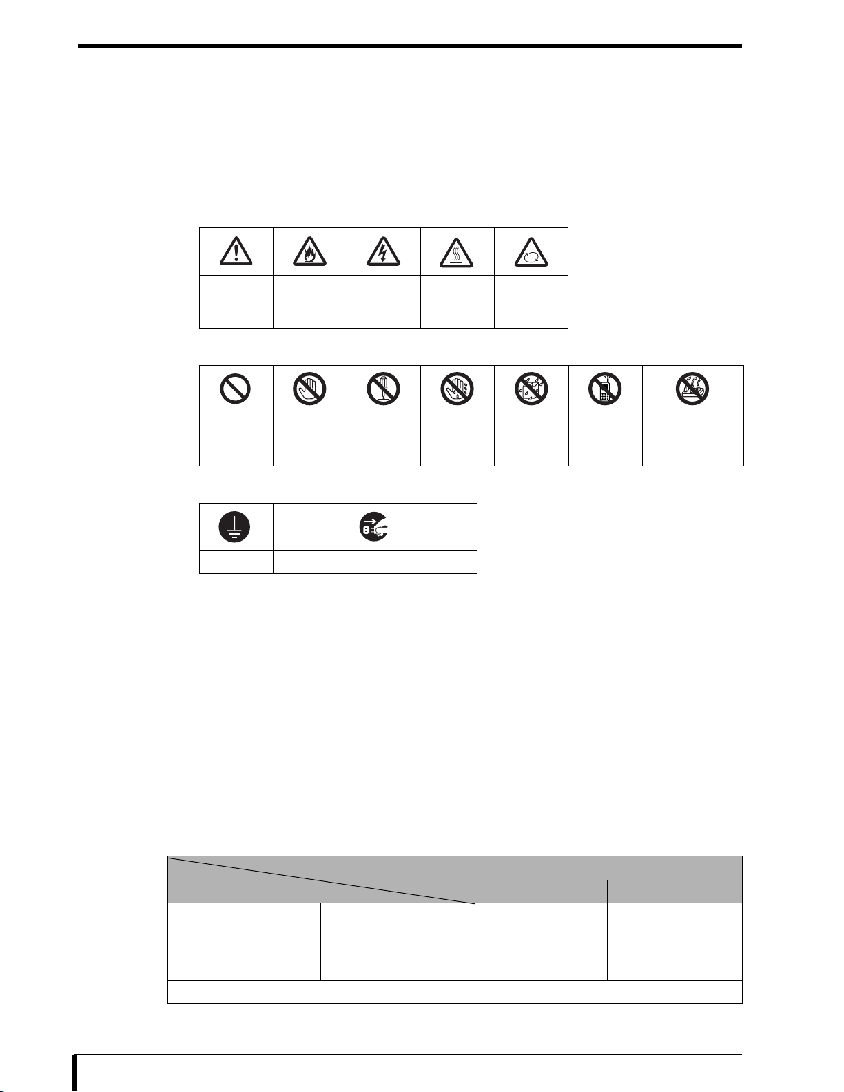
Description of Safety Signage
Symbols indicating that care (including danger and warnings) should be taken:
•
• Prohibition signs (indicating prohibited acts):
• Symbols indicating compulsory or required acts:
Signal Words
Signal words designate a degree or level of hazard seriousness inherent in products.
Signal words include the following three types, which are used according to risk of damage caused by danger and
the severity of damage:
General
Precautions
Prohibited Do not
Ground Remove plug from electrical outlet
Danger of
Fire
touch
Danger of
Electric
Shocks
Do not
disassemble
Danger of
Temperature
touch with
a wet hand
High
Do not
Danger of
Rotation
Do not
expose to
moisture
No mobile
phones
Star-burst
connection
prohibited
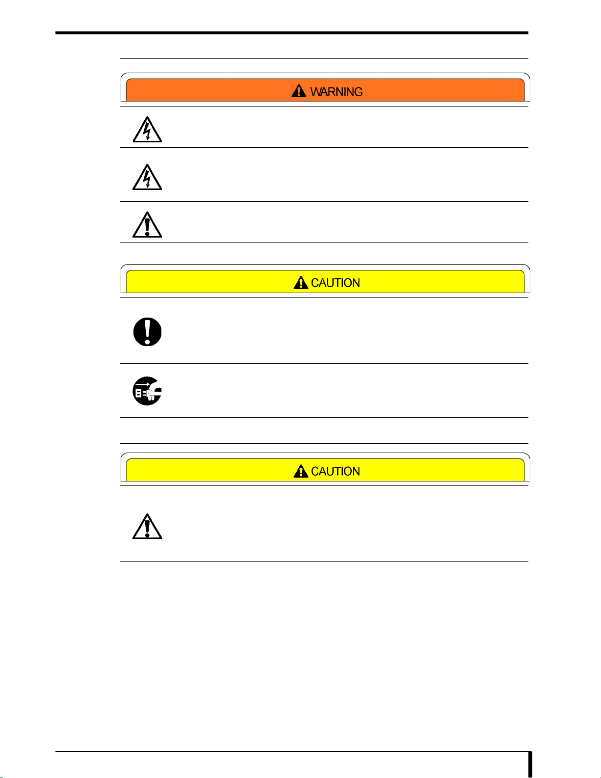
DANGER
Used to indicate an immediate and imminent danger that, if not avoided, is likely to cause death or serious injury,
serious property damage such as total loss of equipment and fire.
WARNING
Used to indicate a consequential (potential) danger that, if not avoided, is likely to cause death or serious injury,
serious property damage such as total loss of equipment and fire.
CAUTION
Used to indicate hazards that, if not avoided, could result in minor or moderate injury or cause partial loss of
equipment and computer data loss.
Risk of damage
High Low
Bodily injury
(or property damage)
Property damage only CAUTION
Death or serious injury
(serious damage)
Minor or moderate injury
(minor damage)
DANGER WARNING
WARNING or
CAUTION
CAUTION
iv
Page 7

Contents
Contents
Introduction......................................................................................... i
How to Read This Manual ................................................................. ii
Structure of This Manual..................................................................ii
Alert Symbol Marks .......................................................................... iv
Signal Words .................................................................................... iv
Chapter 1 Safety Precautions and Warnings...................................1-1
1.1 Warning Labels ........................................................................1-2
1.1.1 Positions and Types of Warning Labels................................ 1-2
1.2 Safety Precautions...................................................................1-4
1.2.1 Precautions Following Requirements of
Laws and Regulations .......................................................... 1-4
1.2.2 General Precautions............................................................. 1-7
1.2.3 Handling Precautions ........................................................... 1-8
1.2.4 Servicing Precautions ........................................................... 1-9
1.2.5 Disposing of Parts................................................................. 1-9
Chapter 2 Before Starting Repair Work ...........................................2-1
2.1 Names of Parts ........................................................................2-2
2.1.1 Unit Exterior.......................................................................... 2-2
2.1.2 Unit Interior ........................................................................... 2-3
2.1.3 Supply Tray........................................................................... 2-3
2.1.4 Lispl-832 (optional) ............................................................... 2-4
2.2 Structure...................................................................................2-4
2.3 Tools, Measuring Instruments, and Jigs Necessary
for Servicing .............................................................................2-5
Chapter 3 Basic Operations.............................................................3-1
3.1 Removing/Installing Supply Tray..............................................3-2
3.2 Opening/Closing Cover............................................................3-4
3.2.1 Opening/Closing Front Cover ............................................... 3-4
3.2.2 Opening/Closing Right Cover ............................................... 3-5
3.3 Removing/Installing Exterior Cover..........................................3-6
3.3.1 Removing/Installing Lower Right Cover................................ 3-6
3.3.2 Removing/Installing Film Ejection Tray............................... 3-10
3.3.3 Removing/Installing Upper Right Cover.............................. 3-12
3.3.4 Removing/Installing Rear Cover ......................................... 3-18
3.3.5 Removing/Installing Rear Cover (Lispl-832) ....................... 3-20
3.3.6 Removing/Installing Left Cover........................................... 3-22
3.4 Installing a Grounding Strap...................................................3-24
3.5 Manually Unlocking the Tray..................................................3-24
Chapter 4 Replacing Supply Unit Loading Parts..............................4-1
4.1 Light Shield Unit.......................................................................4-2
4.1.1 Placing Loading Parts........................................................... 4-2
4.1.2 Removing/Installing Light Shield Assembly .......................... 4-3
4.1.3 Replacing Barrier Bag Detection Sensor .............................. 4-6
4.1.4 Replacing Film Height Detection Sensor .............................. 4-8
4.2 Pickup Unit.............................................................................4-10
4.2.1 Placing Loading Parts......................................................... 4-10
4.2.2 Removing/Installing Pickup Unit Assembly......................... 4-11
4.2.3 Replacing Pickup Transport Motor ..................................... 4-15
4.2.4 Replacing Pickup HP Motor................................................ 4-18
4.2.5 Replacing Pickup HP Sensor ............................................. 4-20
1
Page 8

Contents
Chapter 5 Replacing Tray Unit Loading Parts .................................5-1
5.1 Placing Loading Parts ..............................................................5-2
5.2 Replacing Supply Elevating Motor ...........................................5-3
5.3 Replacing Elevating Plate HP Sensor......................................5-6
5.4 Replacing Tray Lock Solenoid ...............................................5-10
5.5 Replacing Tray Detection Sensor ..........................................5-15
5.6 Replacing Outlet Light Shield Unit Assembly.........................5-20
Chapter 6 Replacing Lispl-832 (Optional) Loading Parts.................6-1
6.1 Light Shield Unit.......................................................................6-2
6.1.1 Placing Loading Parts........................................................... 6-2
6.2 Pickup Unit...............................................................................6-3
6.2.1 Placing Loading Parts........................................................... 6-3
6.3 Supply Unit...............................................................................6-4
6.3.1 Placing Loading Parts........................................................... 6-4
6.3.2 Replacing Elevating Transport Motor ................................... 6-5
6.4 Elevating Transport Unit...........................................................6-8
6.4.1 Removing/Installing Elevating Transport Unit....................... 6-9
6.4.2 Replacing Elevating Transport Nip
Opening/Closing Motor....................................................... 6-13
6.4.3 Replacing Elevating Transport Nip
Opening/Closing HP Sensor............................................... 6-15
6.4.4 Replacing Supply Outlet Sensor......................................... 6-18
Chapter 7 Replacing Sub Scan Unit Loading Parts.........................7-1
7.1 Placing Loading Parts ..............................................................7-2
7.2 Removing/Installing Sub Scan Unit (Including
the Exposure Unit and Position Regulation Unit).....................7-4
7.3 Replacing Sub Scan Unit (Including the
Position Regulation Unit)........................................................7-10
7.4 Replacing Right Cover Detection Sensor...............................7-12
7.5 Replacing Position Regulation Inlet Sensor...........................7-15
7.6 Replacing Position Regulation Transport Motor.....................7-19
7.7 Replacing Moderation belt .....................................................7-23
7.8 Replacing Transfer belt..........................................................7-25
7.9 Replacing Sub Scan Transport Motor....................................7-27
7.10 Replacing Sub Scan Nip Motor..............................................7-30
7.11 Replacing Sub Scan Inlet Sensor ..........................................7-34
7.12 Replacing Sub Scan Nip HP Sensor......................................7-38
7.13 Replacing V-sync Sensor.......................................................7-40
7.14 Replacing Reference Guide...................................................7-44
Chapter 8 Replacing Exposure Unit ................................................8-1
8.1 Placing Exposure Unit..............................................................8-2
8.2 Replacing Exposure Unit..........................................................8-3
Chapter 9 Replacing Loading Parts in Heat Process Unit ............... 9-1
9.1 Heat Process Unit Side............................................................9-2
9.1.1 Removing/Installing Heat Process Unit ................................ 9-3
9.1.2 Replacing Heater.................................................................. 9-7
9.1.3 Replacing Heat Process Temperature Sensor ..................... 9-8
9.1.4 Replacing Supply Cooling Fan ............................................. 9-9
9.2 Main Unit Side........................................................................ 9-11
9.2.1 Replacing Heat Process Motor ........................................... 9-12
9.2.2 Replacing Heat Process Cooling Fans 1 and 2 .................. 9-14
9.2.3 Replacing Deodorant Filter Detection Sensor .................... 9-16
9.2.4 Replacing Insulation Unit Fan............................................. 9-18
9.2.5 Replacing Deodorant Fan................................................... 9-20
2
Page 9

Contents
9.2.6 Replacing Internal Temperature Sensor ............................. 9-22
Chapter 10 Replacing Ejection Unit.................................................10-1
10.1 Placing Ejection Unit ..............................................................10-2
10.2 Replacing Ejection Unit..........................................................10-3
Chapter 11 Replacing Loading Parts in Main Unit........................... 11-1
11.1 Placing Loading Parts ............................................................ 11-2
11.2 Replacing Front Cover Sensor............................................... 11-3
11.3 Replacing Main Board............................................................ 11-7
11.4 Replacing Compact Flash.................................................... 11-11
11.5 Replacing MEC Board..........................................................11-14
11.6 Replacing Multiple Power Supply.........................................11-17
11.7 Replacing H-DRV Board ...................................................... 11-20
11.8 Replacing Noise Filter .......................................................... 11-22
11.9 Replacing Control Cooling Fan ............................................ 11-25
Chapter 12 Replacing Loading Parts in the Exterior of Main Unit....12-1
12.1 Placing Loading Parts ............................................................12-2
12.2 Removing/Installing Exterior of Operation Panel ...................12-3
12.3 Replacing LCD Board ............................................................12-6
12.4 Replacing Status Lamp ..........................................................12-8
12.5 Replacing Operation Switch Board ...................................... 12-11
Chapter 13
Replacing and Cleaning Loading Parts on a Regular Basis
13.1 Periodic Maintenance Tasks ..................................................13-2
13.2 Replacing Pickup Roller.........................................................13-3
13.3 Replacing Opposed Roller .....................................................13-7
13.4 Cleaning Guide ....................................................................13-11
13.5 Cleaning Control Box Intake Air Filter..................................13-13
13.6 Power Supply Unit Intake Air Filter Cleaning .......................13-14
...13-1
Chapter 14 Setting and Adjustment .................................................14-1
14.1 Image Unevenness Correction...............................................14-2
14.1.1 Density Correction .............................................................. 14-3
14.2 Checking and Adjusting Image Data Writing Position..........14-13
14.2.1 Checking Image Data Writing Position ............................. 14-13
14.2.2 Adjusting Main Scan OFFSET (Lateral)
Writing Position................................................................. 14-15
14.2.3 Adjusting Sub Scan OFFSET (Vertical)
Writing Position................................................................. 14-16
14.3 Checking and Fine Tuning the Print Size.............................14-17
14.3.1 Checking Print Size .......................................................... 14-17
14.3.2 Main Scan OFFSET Adjustment ...................................... 14-19
14.3.3 Sub Scan OFFSET Adjustment........................................ 14-20
Chapter 15 DRYPRO 832 Utility Tool ..............................................15-1
15.1 DRYPRO 832 Utility Tool Start ...............................................15-2
15.2 Print Queue/Delete.................................................................15-7
15.3 Print Condition........................................................................15-9
15.4 Test Print ..............................................................................15-12
15.5 Custom Border Setup...........................................................15-14
15.6 QC Pattern ...........................................................................15-15
15.7 Logo Setup...........................................................................15-16
15.8 Film Data..............................................................................15-18
15.9 Film Setup............................................................................15-20
15.10 Calibration Setup..................................................................15-23
3
Page 10

Contents
15.11 System Setup.......................................................................15-25
15.12 Time Layout .........................................................................15-28
15.13 System Reset.......................................................................15-30
15.14 Maintenance Schedule.........................................................15-31
15.15 HPRO Setup ........................................................................15-33
15.16 MEC Setup...........................................................................15-36
15.17 Product Setup ......................................................................15-37
15.18 Image Adjust ........................................................................15-39
15.19 Error History .........................................................................15-41
15.20 Densitometer........................................................................15-42
15.20.1 Built-in Densitometer Calibration ...................................... 15-42
15.20.2 Confirming After Density Calibration................................. 15-49
15.20.3 Creating QC PATTERN BASE.......................................... 15-51
15.21 Data Initialize........................................................................15-54
Chapter 16 MainteTool.....................................................................16-1
16.1 MainteTool Outline .................................................................16-2
16.2 Setting up Network.................................................................16-3
16.2.1 Connecting Service PC ...................................................... 16-3
16.2.2 Setting up Network for Service PC ..................................... 16-4
16.2.3 Sharing the Mainte_Tool Folder.......................................... 16-6
16.3 How to Start the MainteTool ...................................................16-9
16.4 Upgrade Information ............................................................16-12
16.5 Backing up Setup.................................................................16-15
16.5.1 Backup Method up to V1.01 ............................................. 16-15
16.5.2 Backup Method for V1.02 and Later................................. 16-18
16.5.3 Backing Up To MECH EEPROM ...................................... 16-25
16.6 Restoring Settings................................................................16-26
16.6.1 Restore Method up to V1.01............................................. 16-26
16.6.2 Restore Method for V1.02 and Later ................................ 16-29
16.7 Collecting Logs.....................................................................16-33
16.8 Collecting Job Data..............................................................16-37
16.9 IMAGER MEC I/O TEST ......................................................16-39
16.10 IMAGER PRINT I/O TEST ...................................................16-49
16.10.1 Measuring Laser Beam Intensity ...................................... 16-51
Chapter 17 Troubleshooting ............................................................17-1
17.1 Solutions When Trouble Occurs ............................................17-2
17.1.1 The DRYPRO 832 main unit will not start........................... 17-2
17.1.2 The DRYPRO 832 stops during startup.............................. 17-3
17.1.3 An error message is displayed ........................................... 17-4
17.1.4 Film Jam ............................................................................. 17-4
17.1.5 Trouble while using DRYPRO 832 ..................................... 17-4
17.1.6 Does not exit (shutdown).................................................... 17-5
17.1.7 Pickup malfunction trouble ................................................. 17-6
17.1.8 Print Image Trouble ............................................................ 17-7
17.2 Error display and solutions...................................................17-14
17.2.1 Operating panel display and solutions.............................. 17-14
17.2.2 Display and solutions for MainteTool ................................ 17-58
17.3 DRYPRO 832 Unit Replacement Procedure........................17-62
17.3.1 Replacing Main Board ...................................................... 17-63
17.3.2 Replacing the Compact Flash (CF) .................................. 17-64
17.3.3 Replacing the DRYPRO 832 ............................................ 17-82
17.3.4 Replacing Printlink5-IN ..................................................... 17-95
17.3.5 Replacing the MEC Board .............................................. 17-106
4
Page 11

Contents
Chapter 18 Technical Information ...................................................18-1
18.1 Placing Electronic Parts .........................................................18-2
18.1.1 Supply Unit ......................................................................... 18-2
18.1.2 Lispl-832 (Optional) ............................................................ 18-3
18.1.3 Sub Scan Unit, Justification Unit ........................................ 18-4
18.1.4 Heat Process Unit............................................................... 18-5
18.1.5 Ejection Unit ....................................................................... 18-6
18.1.6 Main Unit ............................................................................ 18-6
18.1.7 Exterior of Main Unit ........................................................... 18-7
18.2 Placing Mechanical Parts.......................................................18-8
18.2.1 Supply Unit ......................................................................... 18-8
18.2.2 Lispl-832 ............................................................................. 18-9
18.2.3 Sub Scan Unit, Justification Unit ...................................... 18-10
18.2.4 Exposure Unit ................................................................... 18-11
18.2.5 Heat Process Unit............................................................. 18-12
18.2.6 Ejection Unit ..................................................................... 18-13
18.2.7 Main Unit .......................................................................... 18-13
18.3 Board Diagram.....................................................................18-14
18.3.1 Main Board ....................................................................... 18-14
18.3.2 Main ScanRV, EEP Board Diagram.................................. 18-15
18.3.3 LCD Unit Board Diagram.................................................. 18-16
18.3.4 Operation SW Board Diagram .......................................... 18-16
18.3.5 STATUS LED Board Diagram........................................... 18-17
18.3.6 Multiple Power Supply ...................................................... 18-17
18.3.7 Noise Filter ....................................................................... 18-18
18.3.8 MEC Board Drawing......................................................... 18-19
18.4 Film Management Information .............................................18-21
18.4.1 Management Information Print Specifications .................. 18-21
18.5 Block Diagram......................................................................18-23
18.6 Writing Diagram ...................................................................18-24
18.7 Printing Operation Load Timing Chart (Standard 1 ch) ........18-29
18.8 Printing Operation Load Timing Chart (Standard 2 ch) ........18-30
5
Page 12

Page 13

Chapter
Chapter 1 Safety Precautions and
1
Warnings
This chapter presents safety precautions you need to know prior to
starting repair work on the product.
1.1 Warning Labels..................................................1-2
1.1.1 Positions and Types of Warning Labels ....... 1-2
1.2 Safety Precautions.............................................1-4
1.2.1 Precautions Following Requirements of
Laws and Regulations.................................. 1-4
1.2.2 General Precautions .................................... 1-7
1.2.3 Handling Precautions ................................... 1-8
1.2.4 Servicing Precautions .................................. 1-9
1.2.5 Disposing of Parts ........................................ 1-9
Page 14

Chapter 1 Safety Precautions and Warnings
1.1 Warning Labels
Various warning labels are attached to DRYPRO 832 on locations shown below:
When performing installation or maintenance work such as repairs, understand the meaning of warning labels and
be very careful in handling locations where warning labels are affixed to.
To avoid an accident during servicing work, do not remove or contaminate the label attached to. If the
Caution
1.1.1 Positions and Types of Warning Labels
information on the label is unreadable as it came unstuck or was contaminated, replace the label with a new one.
No. Precautions/Warning Labels
1 Laser Warning
2 Class 1 Laser Product
3 Caution Hot Label
4
Caution Hot (130 ℃ ) Label
1-2
Page 15

Chapter 1 Safety Precautions and Warnings
No. Precautions/Warning Labels
5 Laser Power Label
1-3
Page 16

Chapter 1 Safety Precautions and Warnings
1.2 Safety Precautions
Read all safety precautions thoroughly before using the product.
Be sure to observe the safety precautions described in this section.
1.2.1 Precautions Following Requirements of Laws and Regulations
Caution as to laser control
To prevent danger, make sure that only service engineers who received proper formal
training will remove the exterior cover or touch the inside of the equipment.
DRYPRO 832 Laser Unit Specifications
Item Specifications
Wavelength 784nm
Maximum output 260mW
(1) EMC Statement - DRYPRO 832 has been tested and found to comply with the limits for medical devices to the
IEC 60601-1-2: 2001, Medical Device Directive 93/42/EEC or the Electromagnetic Compatibility Directive 89/
336/EEC (use applicable directive). These limits are designed to provide reasonable protection against harmful
interference in a typical medical installation. DRYPRO 832 generates, uses and can radiate radio frequency
energy and, if not installed and used in accordance with the instructions, may cause harmful interference to other
devices in the vicinity. However, there is no guarantee that interference will not occur in a particular installation.
If DRYPRO 832 does cause harmful interference to other devices, which can be determined by turning the
equipment off and on, the user is encouraged to try to correct the interference by one or more of the following
measures:
- Reorient or relocate the receiving device.
- Increase the separation between the equipment.
- Connect the equipment into an outlet on a circuit different from that to which the other device(s) are connected.
- Consult the manufacturer or field service technician for help.
(2) EMC Statement - Take precautions against DRYPRO MODEL 832 especially regarding EMC. Install and put
into service according to the EMC information provided in the manual.
(3) EMC Statement - Do not use mobile phones or pocket pagers in the vicinity of the DRYPRO MODEL 832. Use
of mobile phones or pocket pagers near the DRYPRO MODEL 832 can cause errors in operation due to
electromagnetic wave interference : such devices should be turned off in the vicinity of the unit.
(4) EMC Statement - Cable List
- AC Power Cable (3m)
(5) EMC Statement - The use of accessories, transducers and cables other than those specified, with the exception of
transducers and cables sold by KONICA MINOLTA MEDICAL & GLAPHIC, INC. as for internal components,
may result in increased emissions or decreased immunity of DRYPRO 832.
(6) EMC Statement - Do not use adjacent to or stacked with other equipment. If adjacent or stacked use is necessary,
confirm normal operation in the configuration in which DRYPRO 832 will be used.
1-4
Page 17
Chapter 1 Safety Precautions and Warnings
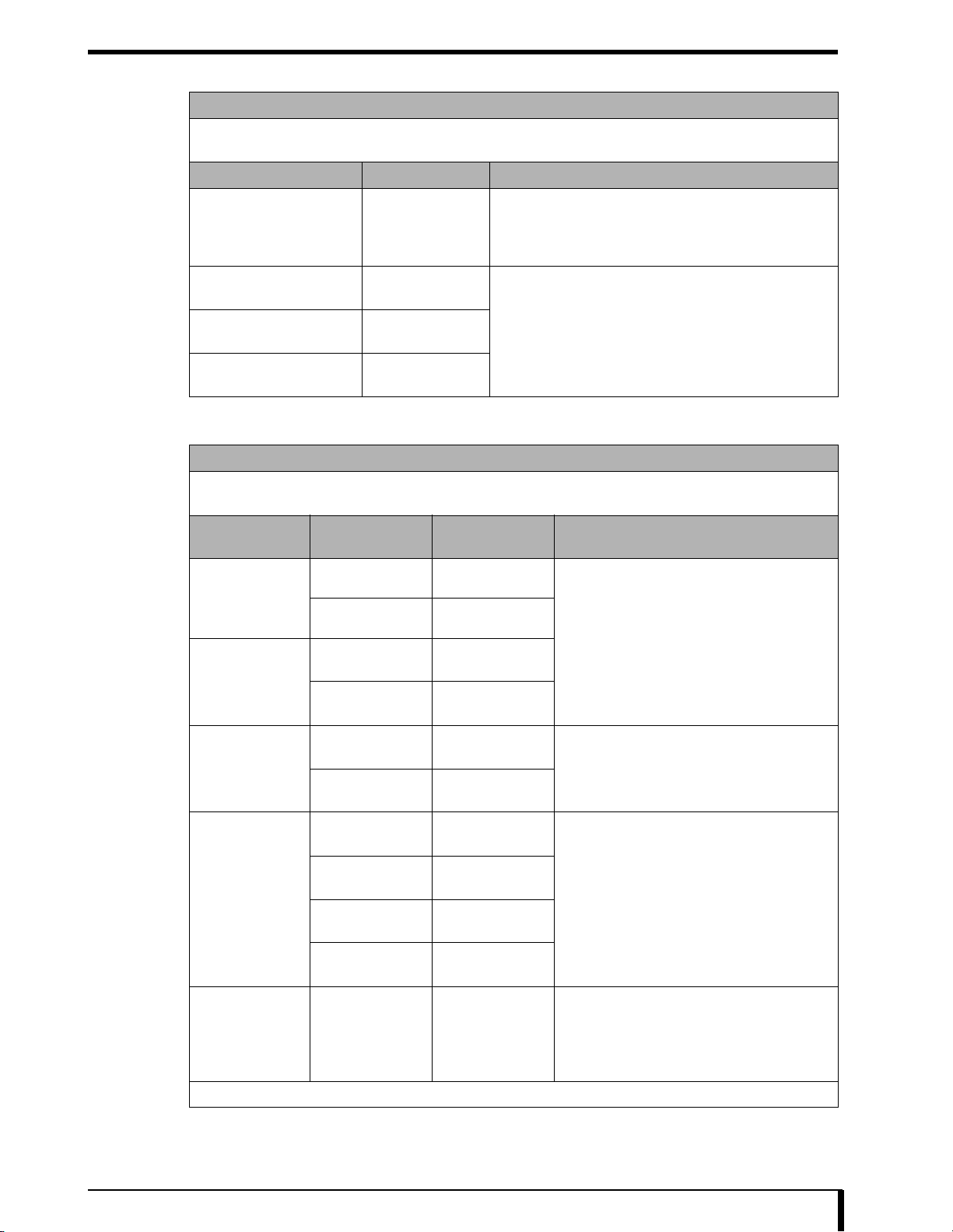
(7) EMC Statement
Guidance and manufacturer's declaration - electromagnetic emissions
The DRYPRO 832 is intended for use in the electromagnetic environment specified below.
The customer or the user of the DRYPRO 832 should assure that it is used in such an environment.
Emissions test Compliance Electromagnetic environment - guidance
The DRYPRO 832 uses RF energy only for its internal
RF emissions
CISPR 11
RF emissions
CISPR 11
Harmonic emissions
IEC 61000-3-2
Voltage fluctuations/flic
IEC 61000-3-3
Group 1
Class B
Class A
Applicable
(8) EMC Statement
Guidance and manufacturer’s declaration - electromagnetic immunity
The DRYPRO 832 is intended for use in the electromagnetic environment specified below.
The customer or the user or the DRYPRO 832 should assure that it is used in such an environment.
Immunity test
IEC 60601
test level
Compliance level Electromagnetic environment - guidance
function. Therefore, its RF emissions are very low and are
not likely to cause any interference in nearby electronic
equipment.
The DRYPRO 832 is suitable for use in all establishments
other than domestic and those directly connected to the
public low-voltage power supply network that supplies
buildings used for domestic purposes.
Electrostatic
discharge (ESD)
IEC 61000-4-2
Electrical fast
transient/burst
IEC 61000-4-4
Surge
IEC 61000-4-5
Voltage dips, short
interruptions and
voltage variations
on power supply
input lines
IEC 61000-4-11
Power frequency
(50/60Hz)
magnetic field
IEC 61000-4-8
±6kV contact ±6kV contact
±8kV air ±8kV air
±2kV for power
supply lines
±1kV for input/
output lines
±1kV
differential mode
±2kV
common mode
T (>95% dip
<5% U
in U
T) for 0.5 cycle
T (60% dip
40% U
in UT) for 5 cycles
T (30% dip
70% U
T) for 25 cycles
in U
T> (<95%
<5% U
dip in U
T) for 5 sec
±2kV for power
supply lines
±1kV for input/
output lines
±1kV
differential mode
±2kV
common mode
T (>95% dip
<5% U
in U
T) for 0.5 cycle
40% UT (60% dip
in UT) for 5 cycles
70% U
T (30% dip
T) for 25 cycles
in U
T> (<95%
<5% U
dip in U
T) for 5 sec
3A/m 3A/m
Floors should be wood, concrete or ceramic tile.
If floors are covered with synthetic material, the
relative humidity should be at least 30%. Mains
power quality should be that of a typical
commercial or hospital environment.
Mains power quality should be that of a typical
commercial or hospital environment.
Mains power quality should be that of a typical
commercial or hospital environment. If the user
of the DRYPRO 832 requires continued
operation during power mains interruptions, it is
recommended that the DRYPRO 832 be
powered from an uninterruptible power supply
or a battery.
Power frequency magnetic fields should be at
levels characteristic of a typical location in a
typical commercial or hospital environment.
[NOTE] U
T is the a.c. mains voltage prior to application of the test level.
1-5
Page 18
Chapter 1 Safety Precautions and Warnings
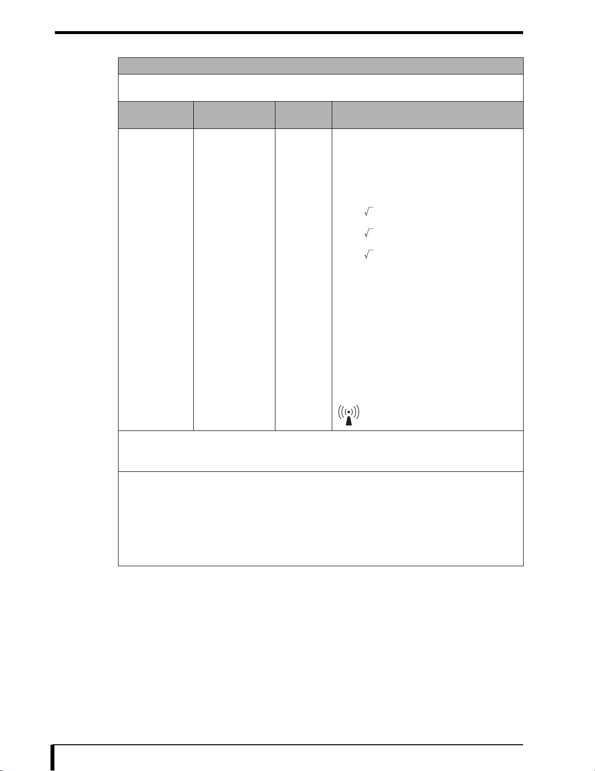
(9) EMC Statement
Guidance and manufacturer’s declaration - electromagnetic immunity
The DRYPRO 832 is intended for use in the electromagnetic environment specified below.
The customer or the user or the DRYPRO 832 should assure that it is used in such an environment.
Immunity test
Conducted RF
IEC 61000-4-6
Radiated RF
IEC 61000-4-3
IEC 60601
test level
3Vrms
150 kHz to 80 MHz
3V/m
80 MHz to 2.5 GHz
Compliance
level
[3]V
[3]V/m
Electromagnetic environment - guidance
Portable and mobile RF communications equipment
should be used no closer to any part of the DRYPRO
832, including cables, than the recommended
separation distance calculated from the equation
applicable to the frequency of the transmitter.
Recommended separation distance
d=[1.2] P
d=[1.2] P 80 MHz to 800 MHz
d=[2.3] P 800 MHz to 2.5 GHz
where P is the maximum output power rating of the
transmitter in watts (W) according to the transmitter
manufacturer and d is the recommended separation
distance in metres (m)
Field strengths from fixed RF transmitters, as
determined by an electromagnetic site survey,
should be less than the compliance level in each
frequency range.
b
a
Interference may occur in the vicinity of equipment
marked with the following symbol:
[NOTE] At 80 MHz and 800 MHz, the higher frequency range applies.
[NOTE] These guidelines may not apply in all situations. Electromagnetic propagation is affected by
absorption and reflection from structures, objects and people.
a Field strengths from fixed transmitters, such as base stations for radio (cellular/cordless) telephones and land
mobile radios, amateur radio, AM and FM radio broadcast and TV broadcast cannot be predicted theoretically
with accuracy. To assess the electromagnetic environment due to fixed RF transmitters, an electromagnetic site
survey should be considered. If the measured field strength in the location in which the DRYPRO 832 is used
exceeds the applicable RF compliance level above, the DRYPRO 832 should be observed to verify normal
operation. If abnormal performance is observed, additional measures may be necessary, such as re- orienting or
relocation the DRYPRO 832.
b Over the frequency range 150 kHz to 80 MHz, field strengths should be less than [3]V/m.
1-6
Page 19

Chapter 1 Safety Precautions and Warnings
(10) EMC Statement
Recommended separation distances between
portable and mobile RF communications equipment and the DRYPRO 832
The DRYPRO 832 is intended for use in and electromagnetic environment in which radiated RF disturbances are
controlled. The customer or the user of the DRYPRO 832 can help prevent electromagnetic interference by
maintaining a minimum distance between portable and mobile RF communications equipment (transmitters) and
the DRYPRO 832 as recommended below, according to the maximum output power of the communications
equipment.
Rated maximum output
power of transmitter
W
0.01 0.12 0.12 0.23
0.1 0.380.380.73
11.21.22.3
10 3.8 3.8 8
100 12 12 23
For transmitters rated at a maximum output power not listed above, the recommended separation distance d in
metres (m) can be estimated using the equation applicable to the frequency of the transmitter, where P is the
maximum output power rating of the transmitter in watts (W) according to the transmitter manufacturer.
[NOTE] At 80 MHz and 800MHz, the separation distance for the higher frequency range applies.
[NOTE] These guidelines may not apply in all situations. Electromagnetic propagation is affected by
absorption and reflection from structures, objects and people.
Separation distance according to frequency of transmitter
m
150 kHz to 80 MHz
d=[1.2] P
80 kHz to 800 MHz
d=[1.2] P
800 kHz to 2.5 GHz
d=[2.3] P
1.2.2 General Precautions
Do not perform work or operation not contained in this manual.
If you accidentally conduct work, you may burn yourself or get an electric shock due to a
hot section and high voltage point contained in this machine.
Make sure to follow safety precautions on warning labels.
Make sure to follow safety precautions contained in this manual and on warning labels
attached to this machine. Failure to observe this caution can cause personal injury or
damage to this machine.
This product is equipped with a laser generator (class 3B).
Avoid eye or skin exposure to direct laser, as it could cause serious injury.
Wear special safety glasses whenever you perform operation check or the like with the
power turned on.
This machine can handle Class 1 laser products with the safety interlock not released.
Anyone with a cardiac pacemaker should keep away from this machine.
There is the danger of causing electromagnetic interference with cardiac pacemakers.
Removing exterior covers
To prevent danger, make sure that only service engineers who received proper formal
training will remove the exterior cover or touch the inside of the product.
1-7
Page 20

Chapter 1 Safety Precautions and Warnings
1.2.3 Handling Precautions
If unusual noise, odor, or smoke comes from this product, stop operation.
If unusual noise, odor, or smoke coming from this product is detected, immediately stop
operation. If you continue to operate it with abnormal condition left as it is, it could cause
an electric shock, fire, or damage to the product.
Be careful not to trip over or trample on the power cable.
If you continue to use the damaged cable, it could cause an electric shock, heat
generation or fire.
Do not remove the power plug by pulling on the power cable.
This could cause a break in the power cable, resulting in heat generation or fire.
Do not put drink or foreign object on the product.
Do not put drink such as juice or foreign objects such as clips and pins on this machine. If
you use this product with water or foreign object such as metals entered in this machine,
it can cause a short in the internal circuit, resulting in fire.
Do not block air intakes or outlets of the product.
If air intakes or outlets of the product are blocked, it can cause failure of the product or
reduce the accuracy of reading images.
Do not leave objects standing on the product or do not step on it.
Failure to observe this caution can cause damage to the product.
Do not use equipment such as mobile phone that emits electromagnetic
waves.
If you use equipment such as mobile phone that emits electromagnetic waves near the
product, it can have negative effect on the product.
1-8
Page 21
1.2.4 Servicing Precautions
Do not insert a piece of wire or metal.
Do not insert foreign objects such as metal strip or wire through vent or gap in the main
unit. Failure to observe this could cause an electric shock.
Be sure to turn OFF when servicing.
If you pull out the circuit board in this machine or remove connectors and cables with the
power turned on, it can cause serious accident.
Make sure to turn OFF the main power supply before starting these operations.
Do not remove lithium batteries carelessly.
The product contains lithium batteries. If you bring a lithium battery near fire or immerse it
in water, it could cause an explosion.
When handling internal electronic components of the product, wear a
wristband.
When handling internal electronic components, wear an antistatic wristband.
If you touch an energized electronic component such as circuit board, it can cause
damage.
Chapter 1 Safety Precautions and Warnings
Unplug the unit or turn OFF the main power supply before cleaning.
Be sure to unplug the unit or turn OFF the main power supply before cleaning this
machine.
You could get your finger caught in sliding or rotating parts.
1.2.5 Disposing of Parts
This DRYPRO 832 product (including lithium batteries), accessories,
optional accessories, consumables, and media are designated as
industrial waste.
When disposing of these, be sure to have them disposed of by authorized industrial
waste disposal firm in accordance with the applicable ordinances and regulations of the
local government.
1-9
Page 22

Page 23

Chapter
Chapter 2 Before Starting Repair
2
Work
This chapter provides basic knowledge about the product before
starting repair work on DRYPRO 832.
2.1 Names of Parts ..................................................2-2
2.1.1 Unit Exterior ................................................. 2-2
2.1.2 Unit Interior................................................... 2-3
2.1.3 Supply Tray .................................................. 2-3
2.1.4 Lispl-832 (optional)....................................... 2-4
2.2 Structure ............................................................2-4
2.3 Tools, Measuring Instruments, and Jigs
Necessary for Servicing.....................................2-5
Page 24

Chapter 2 Before Starting Repair Work
2.1 Names of Parts
Names of the parts that you need to know when installing the DRYPRO 832 unit are shown below.
2.1.1 Unit Exterior
No. Name No. Name
1 Front Cover 2 Lower Front Cover
3 Right Cover 4 Supply Tray
5 Tray Shutter 6 Lower Right Cover
7 Film Ejection Tray 8 Upper Right Cover
9 LAN Cover 10 Rear Cover
11 Left Cover 12 Operation Panel
13 Operation Switch 14 Main Power Supply
15 Cutter Pocket/Cutter 16 Operation Sheet Box
17 Exhaust Ducts
2-2
Page 25

2.1.2 Unit Interior
No. Name No. Name
1 Lever A 2 Lever B
3 Deodorant Filter Case
(Internal: deodorant filter)
Chapter 2 Before Starting Repair Work
4 Stabilizer
5 External Guide Unit Assembly
2.1.3 Supply Tray
No. Name No. Name
1 Film Regulation Pin 2 Cutter Guide
3 Intermediate Plate
2-3
Page 26

Chapter 2 Before Starting Repair Work
2.1.4 Lispl-832 (optional)
No. Name No. Name
1 Right Cover 2 Rear Cover
2.2 Structure
The structure of DRYPRO 832 is shown below.
Film is fed in the order from No. 1 to No. 5 during the printing process.
However, if the Lispl-832 option is installed and film is loaded into the Lispl-832, film is fed in order from No.7 to
No.2.
1 2
No. Name Function
1 Supply Unit Picks up film in the supply tray one by one and transports to the justification
unit.
2 Justification Unit Regulates the horizontal position of the film transported from the supply unit
and transports it to the exposure unit.
3 Exposure Unit Scans laser beam in synchronization with the film transportation and writes
images on the film.
4 Heat Process Unit Processes the exposed film by heating.
5 Cooling Transport Unit Cools and discharges the heat processed film.
6 Deodorant Filter Removes odors emitted during the heat process. Periodic change is needed.
7 Lispl-832 (optional) Picks up film in Lispl-832 one by one and transports to the justification unit.
2-4
Page 27

Chapter 2 Before Starting Repair Work
2.3 Tools, Measuring Instruments, and Jigs Necessary for Servicing
In addition to the standard tools, the following tools, measuring instruments, and jigs are necessary for servicing
DRYPRO 832.
Name Remarks
Allen wrench
Stubby screwdriver
Cutter
Tape such as packaging tape
Laser goggles Those that block the laser wavelength of 784 nm.
Optical power meter The meter that can measure the laser wavelength of 784 nm.
IR card
Densitometer
Ethanol (ethyl alcohol)
Lens cleaner
Melamine foam Used to clean the heat process unit and cool transport unit.
Waste cloth (paper towel)
Vacuum cleaner
Cotton work gloves
Marking-off pin
2-5
Page 28

Page 29

Chapter
Chapter 3 Basic Operations
3
This chapter describes basic operations when repairing DRYPRO
832, including the procedures for installing or removing a supply tray
and exterior cover, opening or closing covers, and wearing a
grounding strap.
3.1 Removing/Installing Supply Tray........................3-2
3.2 Opening/Closing Cover......................................3-4
3.2.1 Opening/Closing Front Cover....................... 3-4
3.2.2 Opening/Closing Right Cover....................... 3-5
3.3 Removing/Installing Exterior Cover....................3-6
3.3.1 Removing/Installing Lower Right Cover ....... 3-6
3.3.2 Removing/Installing Film Ejection Tray ...... 3-10
3.3.3 Removing/Installing Upper Right Cover ..... 3-12
3.3.4 Removing/Installing Rear Cover ................ 3-18
3.3.5 Removing/Installing Rear Cover
(Lispl-832) .................................................. 3-20
3.3.6 Removing/Installing Left Cover .................. 3-22
3.4 Installing a Grounding Strap.............................3-24
3.5 Manually Unlocking the Tray............................3-24
Page 30
Chapter 3 Basic Operations
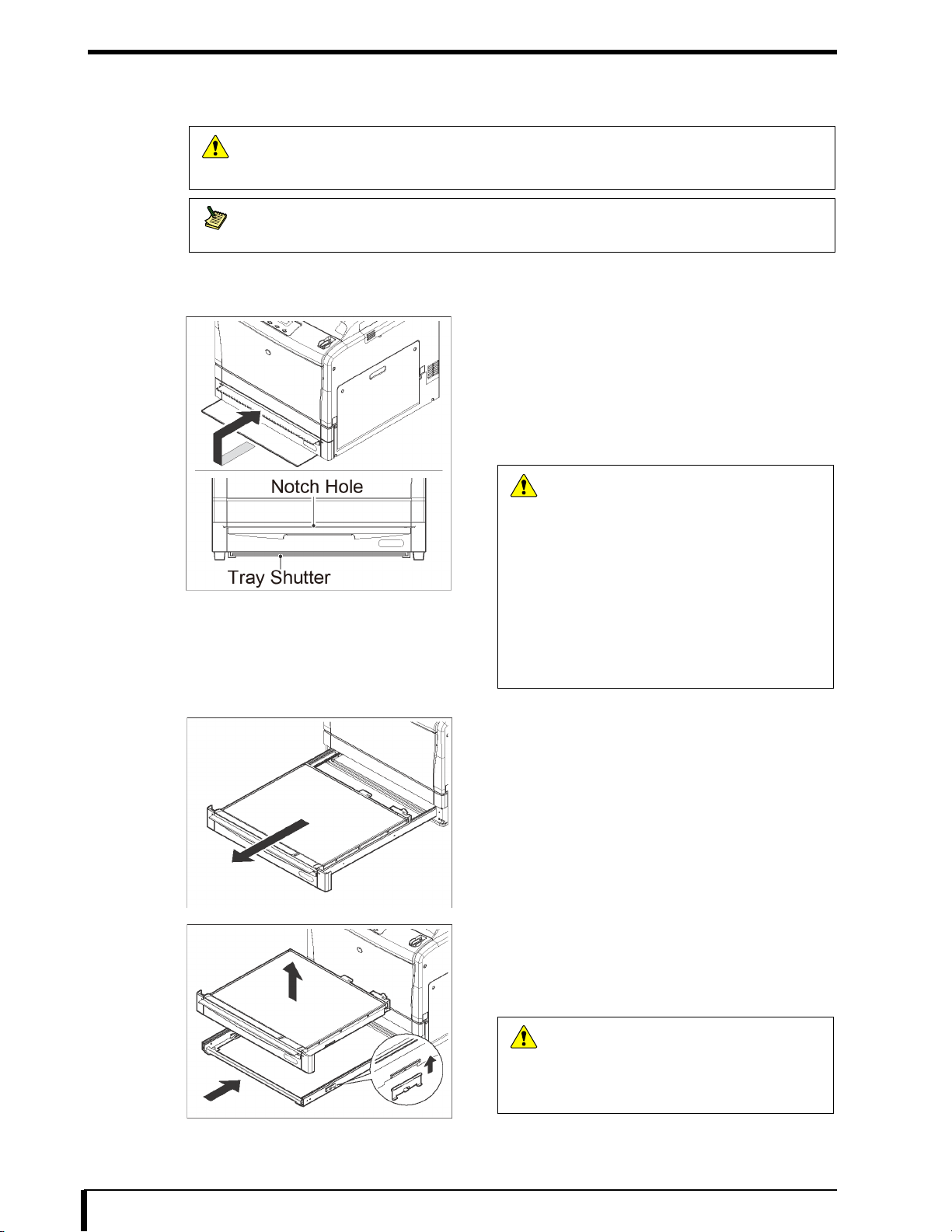
3.1 Removing/Installing Supply Tray
This section describes how to remove/install a supply tray.
Use the procedure for removing a supply tray provided here with power turned OFF when
Caution
installing or repairing DRYPRO 832. For information about how to remove a supply tray with
DRYPRO 832 turned ON, see the operation manual.
• Use the same procedure when removing Lispl-832 tray.
• When removing Lispl-832 tray, pull out the tray shutter on the lower part of Lispl-832.
Note
Removal Procedure
1 Pull the tray shutter out of the lower part of the
supply tray.
2 Insert the tray shutter into the slot in the upper
part of the supply tray with the tray shutter's UP
mark on the top surface toward you.
Inserting the tray shutter as far as it will go unlocks and
causes the supply tray to pop out several centimeters.
Caution
• When replacing loading parts, be sure to
replace with the tray shutter attached.
If some of the film remains on the tray, the
film may be exposed.
• Take sufficient care when handling the
tray shutter, as it may be impossible to
insert if it becomes deformed due to
rough handling.
• If you feel any resistance when inserting
the tray shutter, stop the procedure and
refer to “17.1.7 Pickup malfunction
trouble (Page 17-6)” to fix the problem.
3 Slowly pull out the supply tray fully.
4 Remove the tray from the rails.
Since the tray unit is held in by pins on both sides of the
rails, apply light pressure to remove.
5 Put the rails in the frame.
This is the end of the process of removing the supply tray.
Caution
If you leave the rails protruded, workers or other
people near by may come into contact with the
rails, resulting in personal injury or damage to the
equipment. Make sure to put the rails with the
tray unit removed in the frame.
3-2
Page 31

Installation Procedure
Chapter 3 Basic Operations
1 Pull out the rails.
2 Install the tray on the rails.
Place the supply tray so that the pinhole in the rails aligns
with the pin position on the back of the supply tray. Push in
the supply tray until it clicks into place.
• Be careful not to push the supply tray
Caution
excessively, as it can distort the rails.
• If the tray unit is not positioned properly, it
may interfere with the main unit and it
may become impossible to insert into the
unit.
3 Put the supply tray back into the main unit.
4 Remove the tray shutter and return it to the
previous position.
This is the end of the process of installing the supply tray.
Caution
Take sufficient care when handling the tray
shutter, as it may be impossible to insert if it
becomes deformed due to rough handling.
3-3
Page 32

Chapter 3 Basic Operations
3.2 Opening/Closing Cover
This section describes how to open or close the front cover and right cover.
3.2.1 Opening/Closing Front Cover
This section describes how to open or close the front cover.
How to open the front cover
1 Open the front cover.
The front cover will open by pulling its upper part on both
sides.
Do not push down or place objects on the
Caution
opened front cover. Failure to observe this
caution can cause the breakdown.
This is the end of the process of opening the front cover.
How to close the front cover
This is the end of the process of closing the front cover.
1 Close the front cover.
When closing the front cover, check that the two magnets at
the top edge of the front cover are in the correct position on
the main unit.
3-4
Page 33

3.2.2 Opening/Closing Right Cover
This section describes how to open or close the right cover.
How to open the right cover
Chapter 3 Basic Operations
1 Open the front cover.
The front cover will open by pulling its upper part on both
sides.
Do not push down or place objects on the
Caution
opened front cover. Failure to observe this
caution can cause the breakdown.
2 Open the right cover by rotating the lever B in the
direction of an arrow.
This is the end of the process of opening the right cover.
How to close the cover
This is the end of the process of closing the cover.
1 Close the right and front covers.
3-5
Page 34

Chapter 3 Basic Operations
3.3 Removing/Installing Exterior Cover
3.3.1 Removing/Installing Lower Right Cover
This section describes how to remove/install the lower right cover.
Be sure to turn off power and remove the power cable from the electrical outlet before removing
Caution
or installing the exterior cover or replacing loading parts.
Removal Procedure
1 Pull the tray shutter out of the lower part of the
supply tray.
2 Insert the tray shutter into the slot in the upper
part of the supply tray with the tray shutter's UP
mark on the top surface toward you.
Inserting the tray shutter as far as it will go unlocks and
causes it to pop out several centimeters.
Caution
• When replacing loading parts, be sure to
replace with the tray shutter attached.
If some of the film remains on the tray, the
film may be exposed.
• Take sufficient care when handling the
tray shutter, as it may be impossible to
insert if it becomes deformed due to
rough handling.
• If you feel any resistance when inserting
the tray shutter, stop the procedure and
refer to “17.1.7 Pickup malfunction
trouble (Page 17-6)” to fix the problem.
3 Remove the right cover screws.
・ Two screws (M4×8)
4 Open the front cover.
The front cover will open by pulling its upper part on both
sides.
Do not push down or place objects on the
Caution
opened front cover. Failure to observe this
caution can cause the breakdown.
3-6
Page 35

Chapter 3 Basic Operations
5 Open the right cover by rotating the lever B in the
direction of an arrow.
6 Remove the right cover from the external guide
unit assembly.
Slide the right cover upward, so that the tabs (four places)
inside the right cover are detached from the external guide
assembly, and then remove the cover.
7 Close the front cover and external guide unit
assembly.
8 Remove the lower right cover.
• Four screws (M4×8)
Slide the lower right cover downward so that the tabs (two
locations) on the lower right cover are detached from the
main unit, and then remove the cover.
This is the end of the process of removing the lower right cover.
3-7
Page 36

Chapter 3 Basic Operations
Cover Installation Procedure
1 Install the lower right cover.
• Four screws (M4×8)
Slide the lower right cover upward so that the tabs (two
locations) on the lower right cover hook onto the main unit
to install the cover.
2 Open the front cover.
The front cover will open by pulling its upper part on both
sides.
Do not push down or place objects on the
Caution
opened front cover. Failure to observe this
caution can cause the breakdown.
3 Open the right cover by rotating the lever B in the
direction of an arrow.
4 Install the right cover.
Hook the tabs (four locations) on the inside of the right cover
onto the external guide assembly, and slide the right cover
downward to install.
3-8
Page 37

Chapter 3 Basic Operations
5 Close the right and front covers.
6 Fit the right cover with screws.
• Two screws (M4×8)
7 Put the supply tray back into the main unit.
8 Remove the tray shutter and return it to its
original position.
Caution
This is the end of the process of installing the lower right cover.
Take sufficient care when handling the tray
shutter, as it may be impossible to insert if it
becomes deformed due to rough handling.
3-9
Page 38

Chapter 3 Basic Operations
3.3.2 Removing/Installing Film Ejection Tray
This section describes how to remove/install the film ejection tray.
Be sure to turn off power and remove the power cable from the electrical outlet before removing
Caution
or installing the exterior cover or replacing loading parts.
Removal Procedure
2 Remove the LAN cable from the connector cover
1 Remove the LAN cover.
slots.
3 Disconnect the LAN cable.
4 Remove the film ejection tray.
• Two screws (M4×8)
This is the end of the process of removing the film ejection tray.
3-10
Page 39

Installation Procedure
Chapter 3 Basic Operations
1 Install the film ejection tray.
• Two screws (M4×8)
2 Connect the LAN cable to the ethernet port.
3 Insert the LAN cable into the connector cover
slots.
4 Install the LAN cover.
First insert the tabs (two places) on the top side of the LAN
cover and then insert the tabs on the bottom side (two
places).
This is the end of the process of installing the film ejection tray.
3-11
Page 40

Chapter 3 Basic Operations
3.3.3 Removing/Installing Upper Right Cover
This section describes how to remove/install the upper right cover.
Be sure to turn off power and remove the power cable from the electrical outlet before removing
Caution
or installing the exterior cover or replacing loading parts.
Removal Procedure
1 Pull the tray shutter out of the lower part of the
2 Insert the tray shutter into the slot in the upper
supply tray.
part of the supply tray with the tray shutter's UP
mark on the top surface toward you.
Inserting the tray shutter as far as it will go unlocks and
causes it to pop out several centimeters.
• When replacing loading parts, be sure to
Caution
replace with the tray shutter attached.
If some of the film remains on the tray, the
film may be exposed.
• Take sufficient care when handling the
tray shutter, as it may be impossible to
insert if it becomes deformed due to
rough handling.
• If you feel any resistance when inserting
the tray shutter, stop the procedure and
refer to “17.1.7 Pickup malfunction
trouble (Page 17-6)” to fix the problem.
3 Remove the right cover screws.
• Two screws (M4×8)
4 Open the front cover.
The front cover will open by pulling its upper part on both
sides.
Do not push down or place objects on the
Caution
opened front cover. Failure to observe this
caution can cause the breakdown.
3-12
Page 41

Chapter 3 Basic Operations
5 Open the right cover by rotating the lever B in the
direction of an arrow.
6 Remove the right cover from the external guide
unit assembly.
Slide the right cover upward, so that the tabs (four places)
inside the right cover are detached from the external guide
assembly, and then remove the cover.
7 Close the front cover and external guide unit
assembly.
8 Remove the lower right cover.
• Four screws (M4×8)
Slide the lower right cover downward so that the tabs (two
locations) on the lower right cover are detached from the
main unit, and then remove the cover.
9 Remove the LAN cover.
3-13
Page 42

Chapter 3 Basic Operations
10 Remove the LAN cable from the connector cover
slots.
11 Disconnect the LAN cable.
12 Remove the film ejection tray.
• Two screws (M4×8)
13 Remove the connector cover.
14 Remove the upper right cover.
• Two screws (M4×8)
Slide the upper right cover upward so that the tab (one
location) on the upper right cover is detached from the main
unit, and then remove the cover.
This is the end of the process of removing the upper right cover.
3-14
Page 43

Installation Procedure
Chapter 3 Basic Operations
1 Install the upper right cover.
• Two screws (M4×8)
Slide the upper right cover downward so that the tab (one
location) on the upper right cover hooks onto the main unit
to install the cover.
2 Install the connector cover.
3 Install the film ejection tray.
• Two screws (M4×8)
4 Connect the LAN cable to the ethernet port.
3-15
Page 44

Chapter 3 Basic Operations
5 Insert the LAN cable into the connector cover
slots.
6 Install the LAN cover.
First insert the tabs (two places) on the top side of the LAN
cover and then insert the tabs on the bottom side (two
places).
7 Install the lower right cover.
• Four screws (M4×8)
Slide the lower right cover upward so that the tabs (two
locations) on the lower right cover hook onto the main unit
to install the cover.
8 Open the front cover.
The front cover will open by pulling its upper part on both
sides.
Do not push down or place objects on the
Caution
opened front cover. Failure to observe this
caution can cause the breakdown.
9 Open the right cover by rotating the lever B in the
direction of an arrow.
3-16
Page 45

Chapter 3 Basic Operations
10 Install the right cover.
Hook the tabs (four locations) on the inside of the right cover
onto the external guide assembly, and slide the right cover
downward to install.
11 Close the front and right covers.
12 Fit the right cover with screws.
• Two screws (M4×8)
13 Put the supply tray back into the main unit.
14 Remove the tray shutter and return it to its
original position.
Take sufficient care when handling the tray
Caution
shutter, as it may be impossible to insert if it
becomes deformed due to rough handling.
This is the end of the process of installing the upper right cover.
3-17
Page 46

Chapter 3 Basic Operations
3.3.4 Removing/Installing Rear Cover
This section describes how to remove/install the rear cover.
Be sure to turn off power and remove the power cable from the electrical outlet before removing
Caution
or installing the exterior cover or replacing loading parts.
Removal Procedure
1 Pull the tray shutter out of the lower part of the
supply tray.
2 Insert the tray shutter into the slot in the upper
part of the supply tray with the tray shutter's UP
mark on the top surface toward you.
Inserting the tray shutter as far as it will go unlocks and
causes it to pop out several centimeters.
• When replacing loading parts, be sure to
Caution
replace with the tray shutter attached.
If some of the film remains on the tray, the
film may be exposed.
• Take sufficient care when handling the
tray shutter, as it may be impossible to
insert if it becomes deformed due to
rough handling.
• If you feel any resistance when inserting
the tray shutter, stop the procedure and
refer to “17.1.7 Pickup malfunction
trouble (Page 17-6)” to fix the problem.
3 Remove the rear cover.
This is the end of the process of removing the rear cover.
• Six screws (M4×8)
Remove the upper two screws and the one screw
in the center from the rear cover and loosen the
Note
bottom three.
3-18
Page 47

Installation Procedure
Chapter 3 Basic Operations
1 Install the rear cover.
• Six screws (M4×8)
2 Put the supply tray back into the main unit.
3 Remove the tray shutter and return it to its
original position.
Take sufficient care when handling the tray
Caution
shutter, as it may be impossible to insert if it
becomes deformed due to rough handling.
This is the end of the process of installing the rear cover.
3-19
Page 48

Chapter 3 Basic Operations
3.3.5 Removing/Installing Rear Cover (Lispl-832)
This section describes how to remove/install Lispl-832 tray rear cover.
Be sure to turn off power and remove the power cable from the electrical outlet before removing
Caution
or installing the exterior cover or replacing loading parts.
Removal Procedure
1 Pull the tray shutter out of the lower part of the
supply tray.
2 Insert the tray shutter into the slot in the upper
part of the supply tray with the tray shutter's UP
mark on the top surface toward you.
Inserting the tray shutter as far as it will go unlocks and
causes it to pop out several centimeters.
Caution
• When replacing loading parts, be sure to
replace with the tray shutter attached.
If some of the film remains on the tray, the
film may be exposed.
• Take sufficient care when handling the
tray shutter, as it may be impossible to
insert if it becomes deformed due to
rough handling.
• If you feel any resistance when inserting
the tray shutter, stop the procedure and
refer to “17.1.7 Pickup malfunction
trouble (Page 17-6)” to fix the problem.
3 Remove the rear cover.
This is the end of the process of removing the rear cover.
• Six screws (M4×8)
3-20
Page 49

Installation Procedure
Chapter 3 Basic Operations
1 Install the rear cover.
• Six screws (M4×8)
2 Put the supply tray back into the main unit.
3 Remove the tray shutter and return it to its
original position.
Take sufficient care when handling the tray
Caution
shutter, as it may be impossible to insert if it
becomes deformed due to rough handling.
This is the end of the process of installing the rear cover.
3-21
Page 50

Chapter 3 Basic Operations
3.3.6 Removing/Installing Left Cover
This section describes how to remove/install the left cover.
Be sure to turn off power and remove the power cable from the electrical outlet before removing
Caution
or installing the exterior cover or replacing loading parts.
Removal Procedure
1 Pull the tray shutter out of the lower part of the
supply tray.
2 Insert the tray shutter into the slot in the upper
part of the supply tray with the tray shutter's UP
mark on the top surface toward you.
Inserting the tray shutter as far as it will go unlocks and
causes it to pop out several centimeters.
• When replacing loading parts, be sure to
Caution
replace with the tray shutter attached.
If some of the film remains on the tray, the
film may be exposed.
• Take sufficient care when handling the
tray shutter, as it may be impossible to
insert if it becomes deformed due to
rough handling.
• If you feel any resistance when inserting
the tray shutter, stop the procedure and
refer to “17.1.7 Pickup malfunction
trouble (Page 17-6)” to fix the problem.
3 Remove the left cover.
This is the end of the process of removing the left cover.
• Four screws (M4×8)
Slide the left cover upward so that the tabs (two locations)
on the inside of the left cover detach from the main unit, and
remove the cover.
Remove two screws on the upper part of the left
cover and loosen two screws on the lower part.
Note
3-22
Page 51

Installation Procedure
Chapter 3 Basic Operations
1 Install the left cover.
• Four screws (M4×8)
Slide the left cover downward so that the tabs (two
locations) inside the left cover hook onto the main unit to
install the cover.
2 Put the supply tray back into the main unit.
3 Remove the tray shutter and return it to its
original position.
Take sufficient care when handling the tray
Caution
shutter, as it may be impossible to insert if it
becomes deformed due to rough handling.
This is the end of the process of installing the rear cover.
3-23
Page 52

Chapter 3 Basic Operations
3.4 Installing a Grounding Strap
To avoid damage to the system board caused by electrostatic discharge, wear a wrist
Caution
grounding strap when accessing the system board for work.
3.5 Manually Unlocking the Tray
1 Ground yourself by using a wrist grounding strap
and put the other clip in a metal part of the main
unit that makes a good ground.
Caution
• Manually unlocking the tray is a method of releasing the tray lock when you can not insert
the tray shutter and/or can not pull out the supply tray due to some type of resistance within
the supply unit.
• Because the film inside the supply tray will be exposed when the tray is pulled out by
manually operating the tray lock lever, that film will no longer be usable.
1 Refer to step 3 of “3.3.4 Removing/Installing Rear
Cover (Page 3-18)” and remove the rear cover.
With the Lispl-832, refer to step 3 of “3.3.5
Removing/Installing Rear Cover (Lispl-832)
Note
(Page 3-20)” and remove the rear cover.
2 Pull the tray lock lever towards you.
The tray lock will be released.
3-24
Page 53

Chapter
Chapter 4 Replacing Supply Unit
4
Loading Parts
This chapter describes how to replace loading parts in the supply unit
when they fail and how to adjust after replacing the loading parts.
4.1 Light Shield Unit.................................................4-2
4.1.1 Placing Loading Parts .................................. 4-2
4.1.2
4.1.3 Replacing Barrier Bag Detection Sensor ..... 4-6
4.1.4 Replacing Film Height Detection Sensor ..... 4-8
4.2 Pickup Unit.......................................................4-10
4.2.1 Placing Loading Parts ................................ 4-10
4.2.2
4.2.3 Replacing Pickup Transport Motor............. 4-15
4.2.4 Replacing Pickup HP Motor ....................... 4-18
4.2.5 Replacing Pickup HP Sensor ..................... 4-20
Removing/Installing Light Shield Assembly
Removing/Installing Pickup Unit Assembly
... 4-3
... 4-11
Page 54

Chapter 4 Replacing Supply Unit Loading Parts
4.1 Light Shield Unit
4.1.1 Placing Loading Parts
The light shield unit in the supply unit includes the following loading parts.
No. Name Functions and Reference Sections
1 Barrier bag detection
sensor
2 Film height detection
sensor
This photo sensor detects the presence or absence of the barrier bag.
For more information, see “4.1.3 Replacing Barrier Bag Detection Sensor
(Page 4-6)”.
This photo sensor detects the height of film loaded in the supply tray.
For more information, see “4.1.4 Replacing Film Height Detection Sensor
(Page 4-8)”.
4-2
Page 55

Chapter 4 Replacing Supply Unit Loading Parts
4.1.2 Removing/Installing Light Shield Assembly
This section describes the procedure for removing or installing the light shield unit assembly when replacing loading
parts in the light shield unit.
Be sure to turn off power and remove the power cable from the electrical outlet before removing
Caution
Work outline
The number of personnel and the estimated work hours required to replace load parts is as follows:
or installing the exterior cover or replacing load parts.
Number of
Personnel
1 3 minutes each
Requirements
The procedure for replacing loading parts requires the following tools:
No. To ol s No. Tools
1 Various types of screwdrivers 2
Work Hours
Removal Procedure
1 Pull the tray shutter out of the lower part of the
2 Insert the tray shutter into the slot in the upper
Tray (container for screws and parts removed)
supply tray.
part of the supply tray with the tray shutter's UP
mark on the top surface toward you.
Inserting the tray shutter as far as it will go unlocks and
causes it to pop out several centimeters.
• When replacing loading parts, be sure to
Caution
replace with the tray shutter attached.
If some of the film remains on the tray, the
film may be exposed.
• Take sufficient care when handling the
tray shutter, as it may be impossible to
insert if it becomes deformed due to
rough handling.
• If you feel any resistance when inserting
the tray shutter, stop the procedure and
refer to “17.1.7 Pickup malfunction
trouble (Page 17-6)” to fix the problem.
3 Slowly pull out the supply tray fully.
Do not place objects on, lean on, or apply
Caution
4-3
loads on the pulled out supply tray.
Page 56

Chapter 4 Replacing Supply Unit Loading Parts
4 Remove the lower front cover.
• Two screws (M3×8)
5 Remove the connector (JJ48).
For Lispl-832, remove the Lispl-832 side connector (JJ48).
When removing the connector, do not pull by
Caution
the wires, but hold the tab on the connector
with your fingers.
Pulling by the wires too tightly can cause a
break.
This is the end of the process of removing light shield unit assembly.
• When replacing the barrier bag sensor, go to “4.1.3 Replacing Barrier Bag Detection Sensor (Page 4-6)”.
• When replacing the film height detection sensor, go to “4.1.4 Replacing Film Height Detection Sensor (Page
4-8)”.
Installation Procedure
6 Remove the light shield unit assembly.
• Two screws (M3×8)
When removing the light shield unit
Caution
assembly, be careful not to cause the sensor
to come into contact with the parts inside the
main unit.
1 Install the light shield unit assembly.
• Two screws (M3×8)
When installing the light shield unit
Caution
assembly, be careful not to cause the sensor
to come into contact with the parts inside the
main unit.
4-4
Page 57

Chapter 4 Replacing Supply Unit Loading Parts
2 Connect the connector (JJ48).
For Lispl-832, remove the Lispl-832 side connector (JJ48).
Be sure to push the connector all the way in
Caution
when connecting it.
If the connector is not connected properly,
an error will occur and, in some cases,
smoke and/or an odor may be generated.
3 Install the lower front cover.
• Two screws (M3×8)
4 Put the supply tray back into the main unit.
5 Remove the tray shutter and return it to the
previous position.
Take sufficient care when handling the tray
Caution
shutter, as it may be impossible to insert if it
becomes deformed due to rough handling.
This is the end of the process of installing the light shield unit assembly.
4-5
Page 58

Chapter 4 Replacing Supply Unit Loading Parts
4.1.3 Replacing Barrier Bag Detection Sensor
Replace the photo sensor that detects the presence or absence of the barrier bag.
Be sure to turn off power and remove the power cable from the electrical outlet before removing
Caution
Work outline
The number of personnel and the estimated work hours required to replace load parts is as follows:
or installing the exterior cover or replacing load parts.
Number of
Personnel
15 minutes
Requirements
The procedure for replacing loading parts requires the following tools:
No. To o ls No. To ol s
1 Various types of screwdrivers 2 Tray (container for screws and parts removed)
3 Photo sensor (for replacement)
Work Hours
1 Remove the supply tray, lower front cover,
connector (JJ48), and light shield unit assembly
with reference to “ Removal Procedure (Page
4-3)” in “4.1.2 Removing/Installing Light Shield
Assembly”.
When replacing loading parts, be sure to
Caution
replace with the tray shutter attached.
If some of film remains in the tray, the film
may be exposed.
2 Remove the connector (JP30).
When removing the connector, do not pull by
Caution
the wires, but hold the tab on the connector
with your fingers.
Pulling by the wires too tightly can cause a
break.
3 Push the tab on the back of the sensor inward
and remove the photo sensor.
4 Insert a new photo sensor in the mounting hole.
4-6
Page 59

Chapter 4 Replacing Supply Unit Loading Parts
5 Connect the connector (JP30) removed in step 2.
Be sure to push the connector all the way in when connecting it.
Caution
If the connector is not connected properly, an error will occur and, in some cases, smoke and/or
an odor may be generated.
6 Install the light shield unit assembly, connector (JJ48), and lower front cover with reference to
“ Installation Procedure (Page 4-4)” in “4.1.2 Removing/Installing Light Shield Assembly”.
7 Return the supply tray and tray shutter to their original positions.
Take sufficient care when handling the tray shutter, as it may be impossible to insert if it
Caution
This is the end of the process of replacing the barrier bag detection sensor.
becomes deformed due to rough handling.
4-7
Page 60

Chapter 4 Replacing Supply Unit Loading Parts
4.1.4 Replacing Film Height Detection Sensor
Replace the photo sensor that detects the height of film loaded in the supply tray.
Be sure to turn off power and remove the power cable from the electrical outlet before removing
Caution
Work outline
The number of personnel and the estimated work hours required to replace load parts is as follows:
or installing the exterior cover or replacing load parts.
Number of
Personnel
15 minutes
Requirements
The procedure for replacing loading parts requires the following tools:
No. Tools No. Tools
1 Various types of screwdrivers 2 Tray (container for screws and parts removed)
3 Photo sensor (for replacement)
Work Hours
1 Remove the supply tray, lower front cover,
connector (JJ48), and light shield unit assembly
with reference to “ Removal Procedure (Page
4-3)” in “4.1.2 Removing/Installing Light Shield
Assembly”.
When replacing loading parts, be sure to
Caution
replace with the tray shutter attached.
If some of film remains in the tray, the film
may be exposed.
2 Remove the connector (JP29).
When removing the connector, do not pull by
Caution
the wires, but hold the tab on the connector
with your fingers.
Pulling by the wires too tightly can cause a
break.
3 Push the tab on the back of the sensor inward
and remove the photo sensor.
4 Insert a new photo sensor in the mounting hole.
4-8
Page 61

Chapter 4 Replacing Supply Unit Loading Parts
5 Connect the connector (JP29) removed in step 2.
Be sure to push the connector all the way in when connecting it.
Caution
If the connector is not connected properly, an error will occur and, in some cases, smoke and/or
an odor may be generated.
6 Install the light shield unit assembly, connector (JJ48), and lower front cover with reference to
“ Installation Procedure (Page 4-4)” in “4.1.2 Removing/Installing Light Shield Assembly”.
7 Return the supply tray and tray shutter to their original positions.
Take sufficient care when handling the tray shutter, as it may be impossible to insert if it
Caution
This is the end of the process of replacing the film height detection sensor.
becomes deformed due to rough handling.
4-9
Page 62

Chapter 4 Replacing Supply Unit Loading Parts
4.2 Pickup Unit
4.2.1 Placing Loading Parts
The pickup unit in the supply unit includes the following loading parts.
No. Name Functions and Reference Sections
1 Pickup transport
motor
2 Pickup HP
motor
3 Pickup HP
sensor
This motor drives the pickup roller.
For more information, see “4.2.3 Replacing Pickup Transport Motor (Page
4-15)”.
This drive motor saves the pickup roller.
For more information, see “4.2.4 Replacing Pickup HP Motor (Page 4-18)”.
This photo sensor detects the position where the pickup roller is saved.
For more information, see “4.2.5 Replacing Pickup HP Sensor (Page 4-20)”.
4-10
Page 63

Chapter 4 Replacing Supply Unit Loading Parts
4.2.2 Removing/Installing Pickup Unit Assembly
This section describes the procedure for removing or installing the pickup unit assembly when replacing the loading
parts in the pickup unit assembly.
Be sure to turn off power and remove the power cable from the electrical outlet before removing
Caution
Work outline
The number of personnel and the estimated work hours required to replace load parts is as follows:
or installing the exterior cover or replacing load parts.
Number of
Personnel
1 3 minutes each
Requirements
The procedure for replacing loading parts requires the following tools:
No. Too l s No. To o ls
1 Various types of screwdrivers 2 Tray (container for screws and parts removed)
Work Hours
Removal Procedure
1 Pull the tray shutter out of the lower part of the
2 Insert the tray shutter into the slot in the upper
supply tray.
part of the supply tray with the tray shutter's UP
mark on the top surface toward you.
Inserting the tray shutter as far as it will go unlocks and
causes it to pop out several centimeters.
• When replacing loading parts, be sure to
Caution
replace with the tray shutter attached.
If some of the film remains on the tray, the
film may be exposed.
• Take sufficient care when handling the
tray shutter, as it may be impossible to
insert if it becomes deformed due to
rough handling.
• If you feel any resistance when inserting
the tray shutter, stop the procedure and
refer to “17.1.7 Pickup malfunction
trouble (Page 17-6)” to fix the problem.
3 Slowly pull out the supply tray fully.
Do not place objects on, lean on, or apply
Caution
4-11
loads on the pulled out supply tray.
Page 64

Chapter 4 Replacing Supply Unit Loading Parts
4 Remove the lower front cover.
• Two screws (M3×8)
5 Remove the connector (JJ48).
For Lispl-832, remove the Lispl-832 side connector (JJ48).
When removing the connector, do not pull by
Caution
the wires, but hold the tab on the connector
with your fingers.
Pulling by the wires too tightly can cause a
break.
6 Remove the light shield unit.
• Two screws (M3×8)
When removing the light shield unit
Caution
assembly, be careful not to cause the sensor
to come into contact with the parts inside the
main unit.
7 Remove the pickup unit assembly.
When removing the pickup unit assembly,
Caution
be careful not to cause the sensor to come
into contact with the parts inside the main
unit.
This is the end of the process of removing the pickup unit assembly.
• When replacing the pickup transport motor, go to “4.2.3 Replacing Pickup Transport Motor (Page 4-15)”.
• When replacing the pickup HP motor, go to “4.2.4 Replacing Pickup HP Motor (Page 4-18)”.
• When replacing the pickup HP sensor, go to “4.2.5 Replacing Pickup HP Sensor (Page 4-20)”.
4-12
Page 65

Installation Procedure
Chapter 4 Replacing Supply Unit Loading Parts
1 Install the pickup unit assembly.
Insert the pickup unit assembly all the way in
Caution
along the guides while being careful not to
cause any damage by coming into contact
with the parts inside the main unit.
If the pickup unit assembly is not installed
properly, it may be impossible to install the
light shield unit assembly.
2 Install the light shield unit assembly.
• Two screws (M3×8)
When installing the light shield unit
Caution
assembly, be careful not to cause the sensor
to come into contact with the parts inside the
main unit.
3 Connect the connector (JJ48).
For Lispl-832, remove the Lispl-832 side connector (JJ48).
Be sure to push the connector all the way in
Caution
when connecting it.
If the connector is not connected properly,
an error will occur and, in some cases,
smoke and/or an odor may be generated.
4 Install the lower front cover.
• Two screws (M3×8)
4-13
Page 66

Chapter 4 Replacing Supply Unit Loading Parts
5 Put the supply tray back into the main unit.
6 Remove the tray shutter and return it to the
previous position.
Take sufficient care when handling the tray
Caution
shutter, as it may be impossible to insert if it
becomes deformed due to rough handling.
This is the end of the process of installing the pickup unit assembly.
4-14
Page 67

4.2.3 Replacing Pickup Transport Motor
Replace the motor that drives the pickup roller.
Be sure to turn off power and remove the power cable from the electrical outlet before removing
Caution
Work outline
The number of personnel and the estimated work hours required to replace load parts is as follows:
or installing the exterior cover or replacing load parts.
Chapter 4 Replacing Supply Unit Loading Parts
Number of
Personnel
15 minutes
Requirements
The procedure for replacing loading parts requires the following tools:
No. Too ls No. Tools
1 Various types of screwdrivers 2
3
Replacing Pickup Transport Motor (for replacement)
Work Hours
Tray (container for screws and parts removed)
4 Precision flat blade screwdriver
1 Remove the supply tray, lower front cover,
connector (JJ48), light shield unit assembly and
pickup unit assembly with reference to “
Removal Procedure (Page 4-11)” in “4.2.2
Removing/Installing Pickup Unit Assembly”.
When replacing loading parts, be sure to
Caution
replace with the tray shutter attached.
If some of film remains in the tray, the film
may be exposed.
2 Remove the E ring with a precision screwdriver.
When removing the E ring, be sure not to
Caution
exert too much force. Doing so may cause
you to stab your finger with the precision
screwdriver, or may cause the E ring to
spring out and become lost.
3 Remove the gear.
4 Disconnect the wire from the wire saddles.
• Wire saddles in three locations
4-15
Page 68

Chapter 4 Replacing Supply Unit Loading Parts
5 Remove the bracket.
• Two screws (M3×6)
6 Remove the connector (JP53).
When removing the connector, do not pull by
Caution
the wires, but hold the tab on the connector
with your fingers.
Pulling by the wires too tightly can cause a
break.
7 Remove the pickup transport motor.
• Two screws (M3×6)
8 Install a new pickup transport motor.
• Two screws (M3×6)
9 Connect the connector (JP53) removed in step 6.
Be sure to push the connector all the way in
Caution
when connecting it.
If the connector is not connected properly,
an error will occur and, in some cases,
smoke and/or an odor may be generated.
10 Remove the bracket.
・ One screw (M3×6)
4-16
Page 69

11 Install the bracket removed in step 5.
• Two screws (M3×6)
When a gear or collar comes off in removing the bracket, install by referring to the figure below.
Caution
When attaching a gear or collar, attention should be paid to the gear or collar orientation.
After installing the gear back, move the neighboring gears with your hand to make sure that it
moves in response to the other gears.
12 Install the bracket removed in step 10.
・ One screw (M3×6)
Chapter 4 Replacing Supply Unit Loading Parts
13 Secure the wire removed in step 4 with the wire saddle.
• Wire saddles in three locations
14 Install the gear removed in step 3.
15 Install the E ring removed in step 2.
16 Install the pickup unit assembly, light shield unit assembly, connector (JJ48), and lower front
cover with reference to “ Installation Procedure (Page 4-13)” in “4.2.2 Removing/Installing
Pickup Unit Assembly”.
17 Return the supply tray and tray shutter to their original positions.
Take sufficient care when handling the tray shutter, as it may be impossible to insert if it
Caution
This is the end of the process of replacing the pickup transport motor.
becomes deformed due to rough handling.
4-17
Page 70

Chapter 4 Replacing Supply Unit Loading Parts
4.2.4 Replacing Pickup HP Motor
Replace the drive motor that saves the pickup roller.
Be sure to turn off power and remove the power cable from the electrical outlet before removing
Caution
Work outline
The number of personnel and the estimated work hours required to replace load parts is as follows:
or installing the exterior cover or replacing load parts.
Number of
Personnel
15 minutes
Requirements
The procedure for replacing loading parts requires the following tools:
No. To ol s No. Too ls
1 Various types of screwdrivers 2 Tray (container for screws and parts removed)
3 Pickup HP motor (for replacement)
Work Hours
1 Remove the supply tray, lower front cover,
connector (JJ48), light shield unit assembly and
pickup unit assembly with reference to “
Removal Procedure (Page 4-11)” in “4.2.2
Removing/Installing Pickup Unit Assembly”.
When replacing loading parts, be sure to
Caution
replace with the tray shutter attached.
If some of film remains in the tray, the film
may be exposed.
2 Remove the bracket.
• Two screws (M3×6)
3 Disconnect the wire from the wire saddles.
• Wire saddle in one location
4 Remove the relay connector (JP54).
When removing the connector, do not pull by
Caution
the wires, but hold the tab on the connector
with your fingers.
Pulling by the wires too tightly can cause a
break.
4-18
Page 71

Chapter 4 Replacing Supply Unit Loading Parts
5 Remove the gear.
6 Remove the pickup HP motor.
• Two screws (M3×4)
7 Install a new pickup HP motor.
• Two screws (M3×4)
8 Install the gear removed in step 5.
Push in the gear so that the notch on the gear aligns with the
notch on the shaft.
9 Install the bracket removed in step 2.
• Two screws (M3×6)
You can install it in the correct position by inserting the
notch on the bracket into the slot in the installation position.
10 Connect the relay connector (JP54) removed in step 4.
Be sure to push the connector all the way in when connecting it.
Caution
If the connector is not connected properly, an error will occur and, in some cases, smoke and/or
an odor may be generated.
11 Secure the wire removed in step 3 with the wire saddle.
• Wire saddle in one location
12
Install the pickup unit assembly, light shield unit assembly, connector (JJ48), and lower front cover
with reference to “
Unit Assembly”
Installation Procedure (Page 4-13)”
.
in “4.2.2 Removing/Installing Pickup
13 Return the supply tray and tray shutter to their original positions.
Take sufficient care when handling the tray shutter, as it may be impossible to insert if it
Caution
This is the end of the process of replacing the pickup HP motor.
becomes deformed due to rough handling.
4-19
Page 72

Chapter 4 Replacing Supply Unit Loading Parts
4.2.5 Replacing Pickup HP Sensor
Replace the photo sensor that detects when the pickup roller is in its Home position.
Be sure to turn off power and remove the power cable from the electrical outlet before removing
Caution
Work outline
The number of personnel and the estimated work hours required to replace load parts is as follows:
or installing the exterior cover or replacing load parts.
Number of
personnel
15 minutes
Requirements
The procedure for replacing loading parts requires the following tools:
No. Tools No. Tools
1 Various types of screwdrivers 2 Tray (container for screws and parts removed)
3 Photo sensor (for replacement)
Work Hours
1 Remove the supply tray, lower front cover,
connector (JJ48), light shield unit assembly and
pickup unit assembly with reference to “
Removal Procedure (Page 4-11)” in “4.2.2
Removing/Installing Pickup Unit Assembly”.
When replacing loading parts, be sure to
Caution
replace with the tray shutter attached.
If some of film remains in the tray, the film
may be exposed.
2 Remove the connector (JP31).
When removing the connector, do not pull by
Caution
the wires, but hold the tab on the connector
with your fingers.
Pulling by the wires too tightly can cause a
break.
3 Remove the bracket.
• One screw (M3×6)
4-20
Page 73

Chapter 4 Replacing Supply Unit Loading Parts
4 Push the tab on the back of the sensor inward
and remove the photo sensor.
5 Insert a new photo sensor in the mounting hole.
6 Install the bracket removed in step 3.
• One screw (M3×6)
Fix so that the positioning hole in the bracket aligns with the emboss on the mating part.
7 Connect the connector (JP31) removed in step 2.
Be sure to push the connector all the way in when connecting it.
Caution
If the connector is not connected properly, an error will occur and, in some cases, smoke and/or
an odor may be generated.
8 Install the pickup unit assembly, light shield unit assembly, connector (JJ48), and lower front
cover with reference to “ Installation Procedure (Page 4-13)” in “4.2.2 Removing/Installing
Pickup Unit Assembly”.
9 Return the supply tray and tray shutter to their original positions.
Take sufficient care when handling the tray shutter, as it may be impossible to insert if it
Caution
This is the end of the process of replacing the pickup HP sensor.
becomes deformed due to rough handling.
4-21
Page 74

Page 75

Chapter
Chapter 5 Replacing Tray Unit
5
Loading Parts
This chapter describes how to replace loading parts in the tray unit
when they fail and how to adjust after replacing the loading parts.
5.1 Placing Loading Parts........................................5-2
5.2 Replacing Supply Elevating Motor.....................5-3
5.3 Replacing Elevating Plate HP Sensor................5-6
5.4 Replacing Tray Lock Solenoid .........................5-10
5.5 Replacing Tray Detection Sensor ....................5-15
5.6 Replacing Outlet Light Shield Unit Assembly...5-20
Page 76

Chapter 5 Replacing Tray Unit Loading Parts
5.1 Placing Loading Parts
The tray unit includes the following loading parts.
No. Name Functions and Reference Sections
1 Supply elevating motor This motor drives the elevating plate that moves up when transporting film.
2 Elevating plate HP
sensor
3 Tray lock solenoid This solenoid valve locks or unlocks the supply tray in DRYPRO 832.
4 Tray detection sensor This photo sensor detects presence or absence of the supply tray.
5 Outlet light shield unit
assembly
For more information, see “5.2 Replacing Supply Elevating Motor (Page 5-
3)”.
This photo sensor detects the position (Home Position) when the elevating
plate is lowered.
For more information, see “5.3 Replacing Elevating Plate HP Sensor (Page
5-6)”.
For more information, see “5.4 Replacing Tray Lock Solenoid (Page 5-10)”.
For more information, see “5.5 Replacing Tray Detection Sensor (Page 5-
15)”.
This guide unit assembly is for shading the film inside the supply tray when
the right cover is opened.
For more information, see “5.6 Replacing Outlet Light Shield Unit
Assembly (Page 5-20)”.
5-2
Page 77

5.2 Replacing Supply Elevating Motor
Replace the motor that drives the elevating plate that moves up when transporting film.
Be sure to turn off power and remove the power cable from the electrical outlet before removing
Caution
Work outline
The number of personnel and the estimated work hours required to replace loading parts is as follows:
or installing the exterior cover or replacing loading parts.
Chapter 5 Replacing Tray Unit Loading Parts
Number of
Personnel
15 minutes
Work Hours
Requirements
The procedure for replacing loading parts requires the following tools:
No. Tools No. To o ls
1 Various types of screwdrivers 2 Tray (container for screws and parts
removed)
3 Supply elevating motor (for replacement)
1 Pull the tray shutter out of the lower part of the
supply tray.
2 Insert the tray shutter into the slot in the upper
part of the supply tray with the tray shutter's UP
mark on the top surface toward you.
Inserting the tray shutter as far as it will go unlocks and
causes it to pop out several centimeters.
• When replacing loading parts, be sure to
Caution
replace with the tray shutter attached.
If some of the film remains on the tray, the
film may be exposed.
• Take sufficient care when handling the
tray shutter, as it may be impossible to
insert if it becomes deformed due to
rough handling.
• If you feel any resistance when inserting
the tray shutter, stop the procedure and
refer to “17.1.7 Pickup malfunction
trouble (Page 17-6)” to fix the problem.
• To replace the tray unit supply elevating motor, proceed to step 3.
• To replace the Lispl-832 supply elevating motor, proceed to step 4.
Note
5-3
Page 78

Chapter 5 Replacing Tray Unit Loading Parts
3 Remove the rear cover.
• Six screws (M4×8)
Remove the upper two screws and the one screw
in the center from the rear cover and loosen the
Note
bottom three.
Proceed to step 5.
4 Remove the rear cover of Lispl-832.
・ Six screws (M4×8)
5 Remove the connector.
To replace the tray unit supply elevating motor, remove the
•
connector (JP56).
• To replace the Lispl-832 supply elevating motor, remove
the connector (JP64).
When removing the connector, do not pull by
Caution
the wires, but hold the tab on the connector
with your fingers.
Pulling by the wires too tightly can cause a
break.
6 Remove the supply elevating motor holding
bracket together with the motor.
• One screw (M3×6)
The bracket is hooked on the notch in the main unit, but can
be unhooked by sliding slightly to the right and pulling back.
7 Remove the supply elevating motor.
• Two screws (M3×25)
8 Install a new supply elevating motor.
• Two screws (M3×25)
Align the emboss on the back of the motor with the emboss
on the bracket to determine the installation position.
5-4
Page 79

10 Connect the connector removed in step 5.
If the tray unit supply elevating motor has been replaced, connect the connector (JP56).
•
• If the Lispl-832 supply elevating motor has been replaced, connect the connector (JP64).
Be sure to push the connector all the way in when connecting it.
Caution
If the connector is not connected properly, an error will occur and, in some cases, smoke and/or
an odor may be generated.
11 Install the rear cover or the back cover.
When replacing the tray unit supply elevating motor, refer to “ Installation Procedure (Page 3-19)” in
•
“3.3.4 Removing/Installing Rear Cover” and then attach the rear cover.
• When replacing the Lispl-832 supply elevating motor, refer to “ Installation Procedure (Page 3-21)” in
“3.3.5 Removing/Installing Rear Cover (Lispl-832)” and then attach the back cover.
Chapter 5 Replacing Tray Unit Loading Parts
9 Install the bracket removed in step 6.
• One screw (M3×6)
Hook the notch of the bracket onto the notch of the main unit
to attach.
12 Return the supply tray and tray shutter to their original positions.
Take sufficient care when handling the tray shutter, as it may be impossible to insert if it
Caution
This is the end of the process of replacing the supply elevating motor.
becomes deformed due to rough handling.
5-5
Page 80

Chapter 5 Replacing Tray Unit Loading Parts
5.3 Replacing Elevating Plate HP Sensor
Replace the photo sensor detects the position (Home Position) where the elevating plate is lowered.
Be sure to turn off power and remove the power cable from the electrical outlet before removing
Caution
Work outline
The number of personnel and the estimated work hours required to replace loading parts is as follows:
or installing the exterior cover or replacing loading parts.
Number of
Personnel
15 minutes
Work Hours
Requirements
The procedure for replacing loading parts requires the following tools:
No. Tools No. To o ls
1 Various types of screwdrivers 2 Tray (container for screws and parts
removed)
3 Photo sensor (for replacement)
1 Pull the tray shutter out of the lower part of the
supply tray.
2 Insert the tray shutter into the slot in the upper
part of the supply tray with the tray shutter's UP
mark on the top surface toward you.
Inserting the tray shutter as far as it will go unlocks and
causes it to pop out several centimeters.
• When replacing loading parts, be sure to
Caution
replace with the tray shutter attached.
If some of the film remains on the tray, the
film may be exposed.
• Take sufficient care when handling the
tray shutter, as it may be impossible to
insert if it becomes deformed due to
rough handling.
• If you feel any resistance when inserting
the tray shutter, stop the procedure and
refer to “17.1.7 Pickup malfunction
trouble (Page 17-6)” to fix the problem.
• To replace the tray unit supply elevating motor, proceed to step 3.
• To replace the Lispl-832 supply elevating motor, proceed to step 4.
Note
5-6
Page 81

Chapter 5 Replacing Tray Unit Loading Parts
3 Remove the rear cover.
• Six screws (M4×8)
Remove the upper two screws and the one screw
in the center from the rear cover and loosen the
Note
bottom three.
Proceed to step 5.
4 Remove the rear cover of Lispl-832.
・ Six screws (M4×8)
5 Remove the connector.
To replace the tray unit elevating plate HP sensor, remove
•
the connector (JP56).
• To replace the Lispl-832 elevating plate HP sensor, remove
the connector (JP64).
When removing the connector, do not pull by
Caution
the wires, but hold the tab on the connector
with your fingers.
Pulling by the wires too tightly can cause a
break.
6 Remove the supply elevating motor holding
bracket together with the motor.
• One screw (M3×6)
The bracket is hooked on the notch in the main unit, but can
be unhooked by sliding slightly to the right and pulling back.
7 Remove the connector (JP42).
When removing the connector, do not pull by
Caution
5-7
the wires, but hold the tab on the connector
with your fingers.
Pulling by the wires too tightly can cause a
break.
Page 82

Chapter 5 Replacing Tray Unit Loading Parts
8 Remove the bracket.
• One screw (M3×6)
The bracket is hooked on the notch in the main unit, but can
be unhooked by sliding slightly to the right and pulling back.
9 Push the tab on the back of the sensor inward
and remove the photo sensor.
10 Insert a new photo sensor in the mounting hole.
11 Install the bracket removed in step 8.
• One screw (M3×6)
Insert the bracket into the notch of the main unit, and then
remove after shifting slightly to the left.
12 Connect the connector (JP42) removed in step 7.
Be sure to push the connector all the way in when connecting it.
Caution
If the connector is not connected properly, an error will occur and, in some cases, smoke and/or
an odor may be generated.
13 Install the bracket removed in step 6.
• One screw (M3×6)
Hook the notch of the bracket onto the notch of the main unit
to attach.
5-8
Page 83

Chapter 5 Replacing Tray Unit Loading Parts
14 Connect the connector removed in step 5.
•
If the tray unit elevating plate HP sensor has been replaced, connect the connector (JP56).
• If the Lispl-832 elevating plate HP sensor has been replaced, connect the connector (JP64).
Be sure to push the connector all the way in when connecting it.
Caution
If the connector is not connected properly, an error will occur and, in some cases, smoke and/or
an odor may be generated.
15 Install the rear cover or the back cover.
If the tray unit elevating plate HP sensor has been replaced, refer to “ Installation Procedure (Page 3-19)”
•
in “3.3.4 Removing/Installing Rear Cover” and then attach the rear cover.
• If the Lispl-832 elevating plate HP sensor has been replaced, refer to “ Installation Procedure (Page 3-21)”
in “3.3.5 Removing/Installing Rear Cover (Lispl-832)” and then attach the back cover.
16 Return the supply tray and tray shutter to their original positions.
Take sufficient care when handling the tray shutter, as it may be impossible to insert if it
Caution
This is the end of the process of replacing the elevating plate HP sensor.
becomes deformed due to rough handling.
5-9
Page 84

Chapter 5 Replacing Tray Unit Loading Parts
5.4 Replacing Tray Lock Solenoid
Replace the solenoid valve that locks or unlocks the supply tray.
Be sure to turn off power and remove the power cable from the electrical outlet before removing
Caution
Work outline
The number of personnel and the estimated work hours required to replace loading parts is as follows:
or installing the exterior cover or replacing loading parts.
Number of
Personnel
15 minutes
Work Hours
Requirements
The procedure for replacing loading parts requires the following tools:
No. Too l s No. To o l s
1 Various types of screwdrivers 2 Tray (container for screws and parts
removed)
3 Replacing Tray Lock Solenoid (for replacement)
1 Pull the tray shutter out of the lower part of the
supply tray.
2 Insert the tray shutter into the slot in the upper
part of the supply tray with the tray shutter's UP
mark on the top surface toward you.
Inserting the tray shutter as far as it will go unlocks and
causes it to pop out several centimeters.
• When replacing loading parts, be sure to
Caution
replace with the tray shutter attached.
If some of the film remains on the tray, the
film may be exposed.
• Take sufficient care when handling the
tray shutter, as it may be impossible to
insert if it becomes deformed due to
rough handling.
• If you feel any resistance when inserting
the tray shutter, stop the procedure and
refer to “17.1.7 Pickup malfunction
trouble (Page 17-6)” to fix the problem.
• To replace the tray unit tray lock solenoid, proceed to step 3.
• To replace the Lispl-832 tray lock solenoid, proceed to step 4.
Note
5-10
Page 85

Chapter 5 Replacing Tray Unit Loading Parts
3 Remove the rear cover.
• Six screws (M4×8)
Remove the upper two screws and the one screw
in the center from the rear cover and loosen the
Note
bottom three.
Proceed to step 5.
4 Remove the rear cover of Lispl-832.
・ Six screws (M4×8)
5 Remove the connector.
To replace the tray unit tray lock solenoid, remove the
•
connector (JP56).
• To replace the Lispl-832 tray lock solenoid, remove the
connector (JP64).
When removing the connector, do not pull by
Caution
the wires, but hold the tab on the connector
with your fingers.
Pulling by the wires too tightly can cause a
break.
6 Remove the supply elevating motor holding
bracket together with the motor.
• One screw (M3×6)
The bracket is hooked on the notch in the main unit, but can
be unhooked by sliding slightly to the right and pulling back.
• To replace the tray unit tray lock solenoid, proceed to step 7.
• To replace the Lispl-832 tray lock solenoid, proceed to step 9.
Note
5-11
Page 86

Chapter 5 Replacing Tray Unit Loading Parts
7 Remove the connector cover.
• One screw (M3×6)
If the Lispl-832 is connected, remove the
connector cover after removing the connector
Note
(JP16, JP 26).
8 Remove the cover.
・ Two screws (M3×6)
Proceed to step 10.
9 Remove the Lispl-832 connector cover.
・ Four screws (M3×6)
Remove the connectors (JP16, JP26) before
removing the connector cover.
Note
10 Remove the connectors.
To replace the tray unit tray lock solenoid, remove the
•
connector (JP55, JP44).
• To replace the Lispl-832 tray lock solenoid, remove the
connector (JP63, JP44).
When removing the connector, do not pull by
Caution
the wires, but hold the tab on the connector
with your fingers.
Pulling by the wires too tightly can cause a
break.
5-12
Page 87

Chapter 5 Replacing Tray Unit Loading Parts
11 Remove the tray lock solenoid unit assembly.
• Three screws (M3×6)
The bracket is hooked on the notch in the main unit, but can
be unhooked by sliding slightly to the right and pulling back.
12 Remove the E ring with a precision screwdriver,
and extract the parallel pin.
When removing the E ring, be sure not to
Caution
exert too much force. Doing so may cause
you to stab your finger with the precision
screwdriver, or may cause the E ring to
spring out and become lost.
13 Remove the tray lock solenoid.
14 Install a new tray lock solenoid.
15 Insert the parallel pin that you removed in step
16 Connect the tray lock solenoid unit assembly
17 Connect the connectors removed in step 10.
If the tray unit tray lock solenoid has been replaced, connect the connector (JP55, JP44).
•
• If the Lispl-832 tray lock solenoid has been replaced, connect the connector (JP63, JP44).
• Two screws (M3×6)
• Two screws (M3×6)
12, and install the E ring.
removed in step 11.
• Three screws (M3×6)
After inserting the bracket notch into the notch groove of the
main unit ( in figure on left), align the position of the other
notches and attach.
Be sure to push the connector all the way in when connecting it.
Caution
5-13
If the connector is not connected properly, an error will occur and, in some cases, smoke and/or
an odor may be generated.
Page 88

Chapter 5 Replacing Tray Unit Loading Parts
18 Install the connector cover removed in step 7 or step 9.
• One screw (M3×6)
If connecting the Lispl-832, connect connectors (JP16, JP 26).
Note
• If the tray unit tray lock solenoid has been replaced, proceed to step 19.
• If the Lispl-832 tray lock solenoid has been replaced, proceed to step 20.
Note
19 Install the cover removed in step 8.
• Two screws (M3×6)
20 Install the bracket removed in step 6.
• One screw (M3×6)
Hook the notch of the bracket onto the notch of the main unit
to attach.
21 Connect the connector removed in step 5.
If the tray unit tray lock solenoid has been replaced, connect the connector (JP56).
•
• If the Lispl-832 tray lock solenoid has been replaced, connect the connector (JP64).
Be sure to push the connector all the way in when connecting it.
Caution
If the connector is not connected properly, an error will occur and, in some cases, smoke and/or
an odor may be generated.
22 Install the rear cover or the back cover.
If the tray unit tray lock solenoid has been replaced, refer to “ Installation Procedure (Page 3-19)” in “3.3.4
•
Removing/Installing Rear Cover” and attach the rear cover.
• If the Lispl-832 tray lock solenoid has been replaced, refer to “ Installation Procedure (Page 3-21)” in
“3.3.5 Removing/Installing Rear Cover (Lispl-832)” and then attach the back cover.
23 Return the supply tray and tray shutter to their original positions.
Take sufficient care when handling the tray shutter, as it may be impossible to insert if it
Caution
This is the end of the process of replacing the tray lock solenoid.
becomes deformed due to rough handling.
5-14
Page 89

5.5 Replacing Tray Detection Sensor
Replace the photo sensor that detects the presence or absence of the supply tray.
Be sure to turn off power and remove the power cable from the electrical outlet before removing
Caution
Work outline
The number of personnel and the estimated work hours required to replace loading parts is as follows:
or installing the exterior cover or replacing loading parts.
Chapter 5 Replacing Tray Unit Loading Parts
Number of
Personnel
15 minutes
Work Hours
Requirements
The procedure for replacing loading parts requires the following tools:
No. Too l s No. To ol s
1 Various types of screwdrivers 2 Tray (container for screws and parts removed)
3 Photo sensor (for replacement)
1 Pull the tray shutter out of the lower part of the
supply tray.
2 Insert the tray shutter into the slot in the upper
part of the supply tray with the tray shutter's UP
mark on the top surface toward you.
Inserting the tray shutter as far as it will go unlocks and
causes the supply tray to pop out several centimeters.
• When replacing loading parts, be sure to
Caution
replace with the tray shutter attached.
If some of the film remains on the tray, the
film may be exposed.
• Take sufficient care when handling the
tray shutter, as it may be impossible to
insert if it becomes deformed due to
rough handling.
• If you feel any resistance when inserting
the tray shutter, stop the procedure and
refer to “17.1.7 Pickup malfunction
trouble (Page 17-6)” to fix the problem.
• To replace the tray unit tray detection sensor, proceed to step 3.
• To replace the Lispl-832 tray detection sensor,, proceed to step 4.
Note
5-15
Page 90

Chapter 5 Replacing Tray Unit Loading Parts
3 Remove the rear cover.
• Six screws (M4×8)
Remove the upper two screws and the one screw
in the center from the rear cover and loosen the
Note
bottom three.
Proceed to step 5.
4 Remove the rear cover of Lispl-832.
・ Six screws (M4×8)
5 Remove the connector.
To replace the tray unit tray detection sensor, remove the
•
connector (JP56).
• To replace the Lispl-832 tray detection sensor, remove the
connector (JP64).
Caution
6 Remove the supply elevating motor holding
bracket together with the motor.
• One screw (M3×6)
The bracket is hooked on the notch in the main
unit, but can be unhooked by sliding slightly to the
right and pulling back.
• To replace the tray unit tray detection sensor, proceed to step 7.
• To replace the Lispl-832 tray detection sensor, proceed to step 9.
Note
When removing the connector, do not pull by
the wires, but hold the tab on the connector
with your fingers.
Pulling by the wires too tightly can cause a
break.
5-16
Page 91

Chapter 5 Replacing Tray Unit Loading Parts
7 Remove the connector cover.
• One screw (M3×6)
If the Lispl-832 is connected, remove the
connector cover after removing the connector
Note
(JP16, JP 26).
8 Remove the cover.
・ Four screws (M3×6)
Proceed to step 10.
9 Remove the Lispl-832 connector cover.
・ Four screws (M3×6)
Remove the connectors (JP16, JP26) before
removing the connector cover.
Note
10 Remove the connectors.
To replace the tray unit tray detection sensor, remove the
•
connector (JP55, JP44).
• To replace the Lispl-832 tray detection sensor, remove the
connector (JP63, JP44).
When removing the connector, do not pull by
Caution
the wires, but hold the tab on the connector
with your fingers.
Pulling by the wires too tightly can cause a
break.
5-17
Page 92

Chapter 5 Replacing Tray Unit Loading Parts
11 Remove the tray lock solenoid unit assembly.
• Three screws (M3×6)
The bracket is hooked on the notch in the main unit, but can
be unhooked by sliding slightly to the right and pulling back.
12 Push the tab on the back of the sensor inward
and remove the photo sensor.
13 Insert a new photo sensor in the mounting hole.
14 Install the tray lock solenoid unit assembly
removed in step 11.
• Three screws (M3×6)
After inserting the bracket notch into the notch groove of the
main unit ( in figure on left), align the position of the other
notches and attach.
15 Connect the connectors removed in step 10.
If the tray unit tray detection sensor has been replaced, connect the connector (JP55, JP44).
•
• If the Lispl-832 tray detection sensor has been replaced, connect the connector (JP63, JP44).
Be sure to push the connector all the way in when connecting it.
Caution
If the connector is not connected properly, an error will occur and, in some cases, smoke and/or
an odor may be generated.
16 Install the connector cover removed in step 7 or step 9.
• One screw (M3×6)
If connecting the Lispl-832, connect connectors (JP16, JP 26).
Note
• If the tray unit tray detection sensor has been replaced, proceed to step 17.
• If the Lispl-832 tray detection sensor has been replaced, proceed to step 18.
Note
5-18
Page 93

17 Install the cover removed in step 8.
• Two screws (M3×6)
18 Install the bracket removed in step 6.
19 Connect the connector removed in step 5.
If the tray unit tray detection sensor has been replaced, connect the connectors (JP56).
•
• If the Lispl-832 tray detection sensor has been replaced, connect the connector (JP64).
Be sure to push the connector all the way in when connecting it.
Caution
If the connector is not connected properly, an error will occur and, in some cases, smoke and/or
an odor may be generated.
Chapter 5 Replacing Tray Unit Loading Parts
• One screw (M3×6)
Hook the notch of the bracket onto the notch of the main unit
to attach.
20 Install the rear cover.
If the tray unit tray detection sensor has been replaced, refer to “ Installation Procedure (Page 3-19)” in
•
“3.3.4 Removing/Installing Rear Cover” and attach the rear cover.
• If the Lispl-832 tray detection sensor has been replaced, refer to “ Installation Procedure (Page 3-21)” in
“3.3.5 Removing/Installing Rear Cover (Lispl-832)” and then attach the back cover.
21 Return the supply tray and tray shutter to their original positions.
Take sufficient care when handling the tray shutter, as it may be impossible to insert if it
Caution
This is the end of the process of replacing the tray detection sensor.
becomes deformed due to rough handling.
5-19
Page 94

Chapter 5 Replacing Tray Unit Loading Parts
5.6 Replacing Outlet Light Shield Unit Assembly
Replace the outlet light shield unit assembly that is used for shading the film inside the supply tray when the right
cover is opened.
• Be sure to turn OFF power and remove the power cable from the electrical outlet before
Caution
Work outline
The number of personnel and the estimated work hours required to replace loading parts is as follows.
removing or installing the exterior cover or replacing loading parts.
• If the Lispl-832 is installed, start the procedure from step 7 after referring to “ Removal
Procedure (Page 6-9)” in “6.4.1 Removing/Installing Elevating Transport Unit” and removing
the elevating transport unit.
Number of
Personnel
1 10 minutes
Requirements
The procedure for replacing loading parts requires the following tools:
No. Tools No. To o ls
1 Various types of screwdrivers 2
3
Outlet light shield unit assembly (for replacement)
Work Hours
Tray (container for screws and parts removed)
1 Pull the tray shutter out of the lower part of the
supply tray.
2 Insert the tray shutter into the slot in the upper
part of the supply tray with the tray shutter’s UP
mark on the top surface toward you.
Inserting the tray shutter as far as it will go unlocks and
causes it to pop out several centimeters.
• When replacing loading parts, be sure to
Caution
replace with the tray shutter attached.
If some of the film remains on the tray, the
film may be exposed.
• Take sufficient care when handling the
tray shutter, as it may be impossible to
insert if it becomes deformed due to
rough handling.
• If you feel any resistance when inserting
the tray shutter, stop the procedure and
refer to “17.1.7 Pickup malfunction
trouble (Page 17-6)” to fix the problem.
3 Remove the screws from the right cover.
・ Two screws (M4×8)
5-20
Page 95

Chapter 5 Replacing Tray Unit Loading Parts
4 Open the front cover.
The front cover will open by pulling the upper part of both
sides.
Do not push down or place objects on the
Caution
opened front cover. Failure to observe this
caution can cause the front cover to break.
5 Open the right cover by rotating the lever B in the
direction of an arrow.
6 Remove the right cover from the external guide
unit assembly.
Slide the right cover upward, so that the tabs (four places)
inside the right cover are detached from the external guide
assembly, and then remove the cover.
7 Open the external guide unit assembly after removing
the stop bands at two places.
• If the Lispl-832 is not installed, continue to step 8.
• If the Lispl-832 is installed, continue directly to step 10.
Note
5-21
Page 96

Chapter 5 Replacing Tray Unit Loading Parts
8 Remove the outlet light shield unit assembly.
・ Four screws
9 Install the new outlet light shield unit assembly.
・ Four screws
Continue to step 13.
10 Remove the outlet light shield unit assembly.
・ Four screws
11 Install the new outlet light shield unit assembly.
・ Four screws
12 Install the elevating transport unit with reference
to
“ Installation Procedure (Page 6-11)” in
“6.4.1 Removing/Installing Elevating Transport
Unit”.
13 Install the guide unit assembly by hooking the stop bands from step 7 in two locations on the
external guide unit assembly.
14 Install the right cover.
Hook the tabs (four locations) on the side of the right cover
onto the external guide assembly, and slide the right cover
downward to install.
15 Close the right and front covers.
16 Fit the right cover with removed screws in step 3.
・ Two s c r e ws (M4×8)
17 Put the supply tray back into the main unit.
18 Remove the tray shutter and return it to the
previous position.
Take sufficient care when handling the tray
Caution
This is the end of the process of installing the outlet light shield
unit assembly.
5-22
shutter, as it may be impossible to insert if it
becomes deformed due to rough handling.
Page 97

Chapter
Chapter 6 Replacing Lispl-832
6
(Optional) Loading Parts
This chapter describes how to replace loading parts in Lispl-832
(optional) when they fail and how to adjust after replacing the loading
parts.
6.1 Light Shield Unit.................................................6-2
6.1.1 Placing Loading Parts .................................. 6-2
6.2 Pickup Unit.........................................................6-3
6.2.1 Placing Loading Parts .................................. 6-3
6.3 Supply Unit.........................................................6-4
6.3.1 Placing Loading Parts .................................. 6-4
6.3.2 Replacing Elevating Transport Motor........... 6-5
6.4 Elevating Transport Unit ....................................6-8
6.4.1 Removing/Installing Elevating
Transport Unit............................................... 6-9
6.4.2 Replacing Elevating Transport Nip
Opening/Closing Motor .............................. 6-13
6.4.3 Replacing Elevating Transport Nip
Opening/Closing HP Sensor ...................... 6-15
6.4.4 Replacing Supply Outlet Sensor ................ 6-18
Page 98

Chapter 6 Replacing Lispl-832 (Optional) Loading Parts
6.1 Light Shield Unit
6.1.1 Placing Loading Parts
The Lispl-832 light shield unit includes the following loading parts.
No. Name Functions and Reference Sections
1 Barrier bag detection
sensor
2 Film height detection
sensor
This photo sensor detects the presence or absence of the barrier bag.
Use the same replacement procedure as that for replacing the supply unit.
For more information, see “4.1.3 Replacing Barrier Bag Detection Sensor
(Page 4-6)”.
This photo sensor detects the height of film loaded in the supply tray.
Use the same replacement procedure as that for replacing the supply unit.
For more information, see “4.1.4 Replacing Film Height Detection Sensor
(Page 4-8)”.
6-2
Page 99

6.2 Pickup Unit
6.2.1 Placing Loading Parts
The Lispl-832 pickup unit includes the following loading parts.
Chapter 6 Replacing Lispl-832 (Optional) Loading Parts
No. Name Functions and Reference Sections
1 Pickup transport
motor
2 Pickup and Save
motor
3 Pickup and Save
sensor
This motor drives the pickup roller.
Use the same replacement procedure as that for replacing the supply unit.
For more information, see “4.2.3 Replacing Pickup Transport Motor (Page
4-15)”.
This drive motor saves the pickup roller.
Use the same replacement procedure as that for replacing the supply unit.
For more information, see “4.2.4 Replacing Pickup HP Motor (Page 4-18)”.
This photo sensor detects the position where the pickup roller is saved.
Use the same replacement procedure as that for replacing the supply unit.
For more information, see “4.2.5 Replacing Pickup HP Sensor (Page 4-20)”.
6-3
Page 100

Chapter 6 Replacing Lispl-832 (Optional) Loading Parts
6.3 Supply Unit
6.3.1 Placing Loading Parts
The Lispl-832 supply unit includes the following loading parts.
No. Name Functions and Reference Sections
1 Supply elevating motor This motor drives the elevating plate that moves up when transporting film.
Use the same replacement procedure as that for replacing the tray unit.
For more information, see “5.2 Replacing Supply Elevating Motor (Page 5-
3)”.
2 Elevating plate HP
sensor
3 Tray lock solenoid This solenoid valve locks or unlocks the supply tray in DRYPRO 832.
4 Tray detection sensor This photo sensor detects presence or absence of the supply tray.
5 Elevating transport motor This motor transports film from the Lispl-832.
This photo sensor detects the position (Home Position) when the elevating
plate is lowered.
Use the same replacement procedure as that for replacing the tray unit.
For more information, see “5.3 Replacing Elevating Plate HP Sensor (Page
5-6)”.
Use the same replacement procedure as that for replacing the tray unit.
For more information, see “5.4 Replacing Tray Lock Solenoid (Page 5-10)”.
Use the same replacement procedure as that for replacing the tray unit.
For more information, see “5.5 Replacing Tray Detection Sensor (Page 5-
15)”.
For more information, see “6.3.2 Replacing Elevating Transport Motor
(Page 6-5)”.
6-4
 Loading...