

Page 1
1179-7744-03.fm Page 0 Thursday, November 9, 2000 1:47 PM
SETUP INSTRUCTIONS
CF9001
NOTE
•Keep all packing materials out of the reach of children.
•Before setting up, be sure to unplug the power cord of the copier.
•Keep all packing materials until you transport the machine to the customer.
1179-7744-03 © MINOLTA CO., LTD. Printed in Japan
Page 2
1179-7744-03.fm Page 1 Thursday, November 9, 2000 1:47 PM
UNPACKING
■
1. Check to see that the following items are contained in the box of accessories.
CF9001
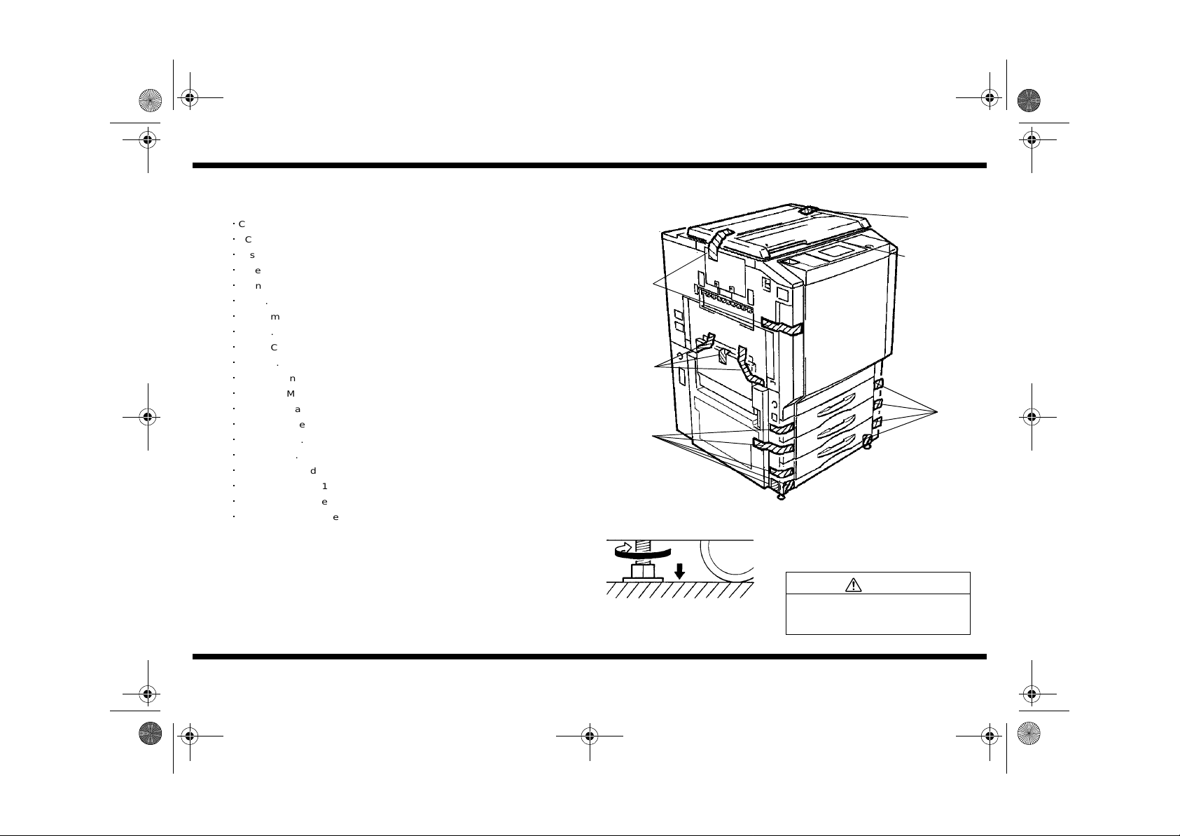
2. Peel off the pieces of tape and remove the cushions from the copier.
For Europe : Unwrap the power cord and plug it into the copier.
Copy Tray.................................................................................................1
PC Drum...................................................................................................1
Fusing Oil (For the U.S.A.).......................................................................1
Tube.........................................................................................................1
Syringe.....................................................................................................1
Cover........................................................................................................1
PC Drum Key ...........................................................................................1
Spring.......................................................................................................1
Starter Chute............................................................................................4
Labels................................................................................................. 1 set
Jumper Harness.......................................................................................1
Operator's Manual (For the U.S.A.)..........................................................1
Operator's Manual Holder ........................................................................1
Creative Image Book................................................................................1
Quick Guide..............................................................................................1
Stopper.....................................................................................................1
Mag Roller Shield.....................................................................................4
Screw (9739-0408-14)..............................................................................1
Power Cord (For the U.S.A.)....................................................................1
Customer Warranty Registration (For the U.S.A.)....................................1
Tape
Tape
Tape
ADJUSTING THE FEET
■
1179N001AA
Tape
Sheet
Tape
1179U001AC
Using a wrench, turn the Support Feet found
underneath the copier near the front two
corners.
CAUTION
To reduce the risk of injury due to
unstable equipment, adjust the Support
Feet before use.
1179-7744-03
– 1 –
Page 3
1179-7744-03.fm Page 2 Thursday, November 9, 2000 1:47 PM
CF9001
1144U003KA
1144U007KA
4460N001AA
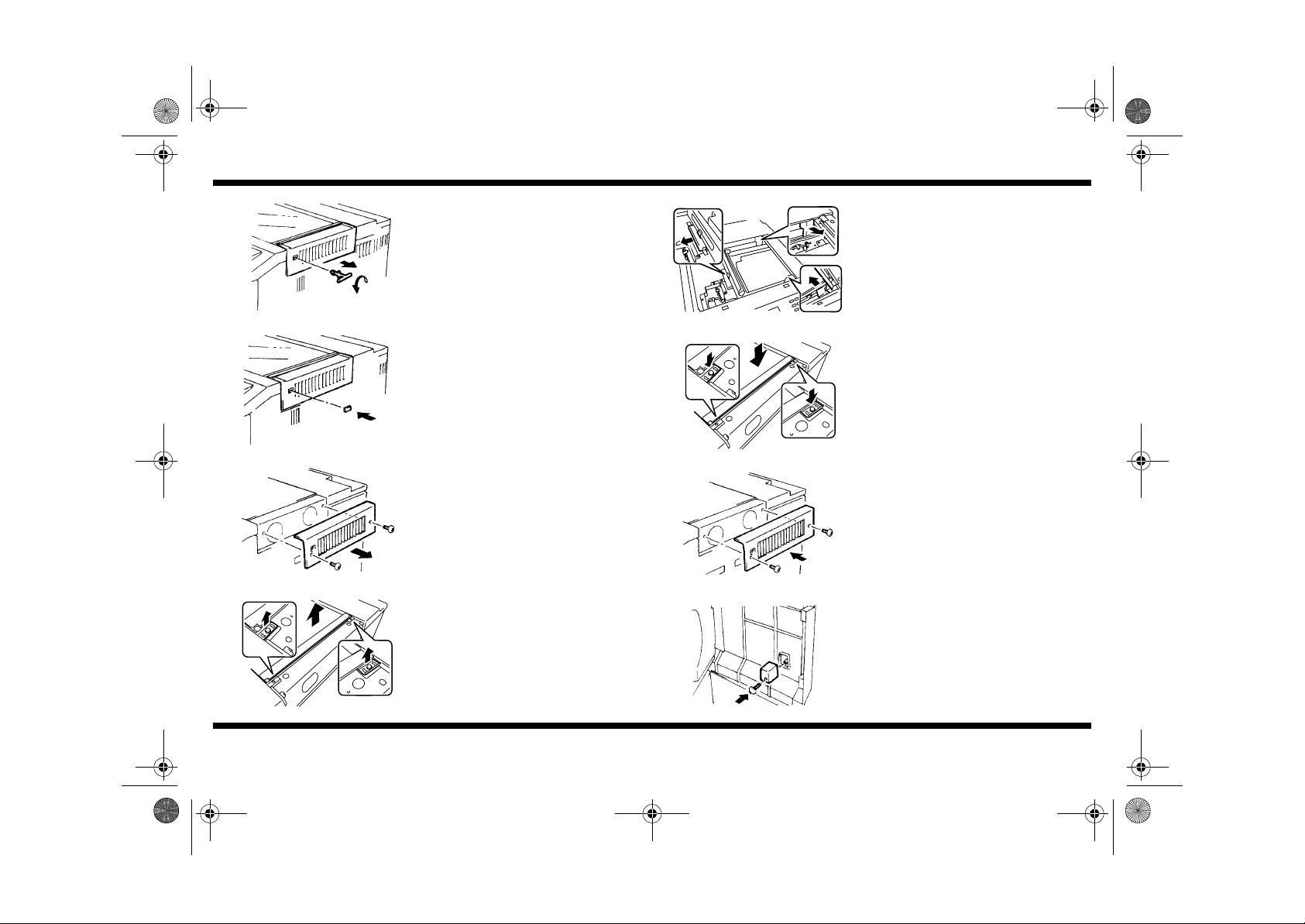
1. Turn the scanner locking pin about 90
°
counterclockwise and pull it out.
2. Attach the cover to the hole left by the
locking pin.
3. Remove the Right Upper Cover.
4. Remove two Original Glass Holders and
remove the Original Glass.
5. Remove three cushions and one Fixing
Plate.
1179U024AB
6. Install the Original Glass.
1179U023AA
7. Install the Right Upper Cover.
4447U054AA
8. Open the front door and secure the stopper
to the door with a screw.
Screw (4x8) x 1
1179U022AA
1179-7744-03
1144U011AA
– 2 –
Page 4
1179-7744-03.fm Page 3 Thursday, November 9, 2000 1:47 PM
CF9001
1154U002AA
1179U002AA
1179U003AB
Holding
Plate
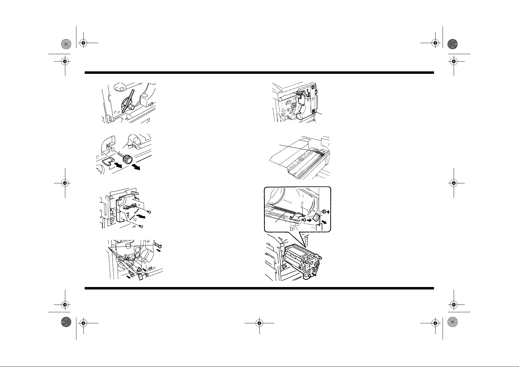
9. Remove the cushion packed above the
transfer drum lock release handle.
10.Pull off knob M9 and transfer unit lock lever
M4.
11.Remove 4 screws and the transfer unit cover.
12.Pull off the stops from the Transfer unit rails.
Remove the holding plate from the Transfer
unit corona assy.
1144U090KA
Tape
1144U082AB
Cushioning
Sheet
Holding Plate
protective
sheet
13.Remove the tape and the protective sheet
from the hopper unit.
14.Pull out the transfer drum unit and remove
the tape from the transfer drum.
15.Remove the cushioned holding plate
attached to the frame underneath the
Transfer Drum. Then pull out the cushioning
sheet.
Check to see if there are any hollows in the
Transfer Film while turning the drum
counterclockwise. If there are any hollows,
tightly wrap the Film around the drum again.
Refer to the Service Manual for the
procedure.
1179U004AA
1179-7744-03
179U021AB
– 3 –
Page 5
NOTES
1179-7744-03.fm Page 4 Thursday, November 9, 2000 1:47 PM
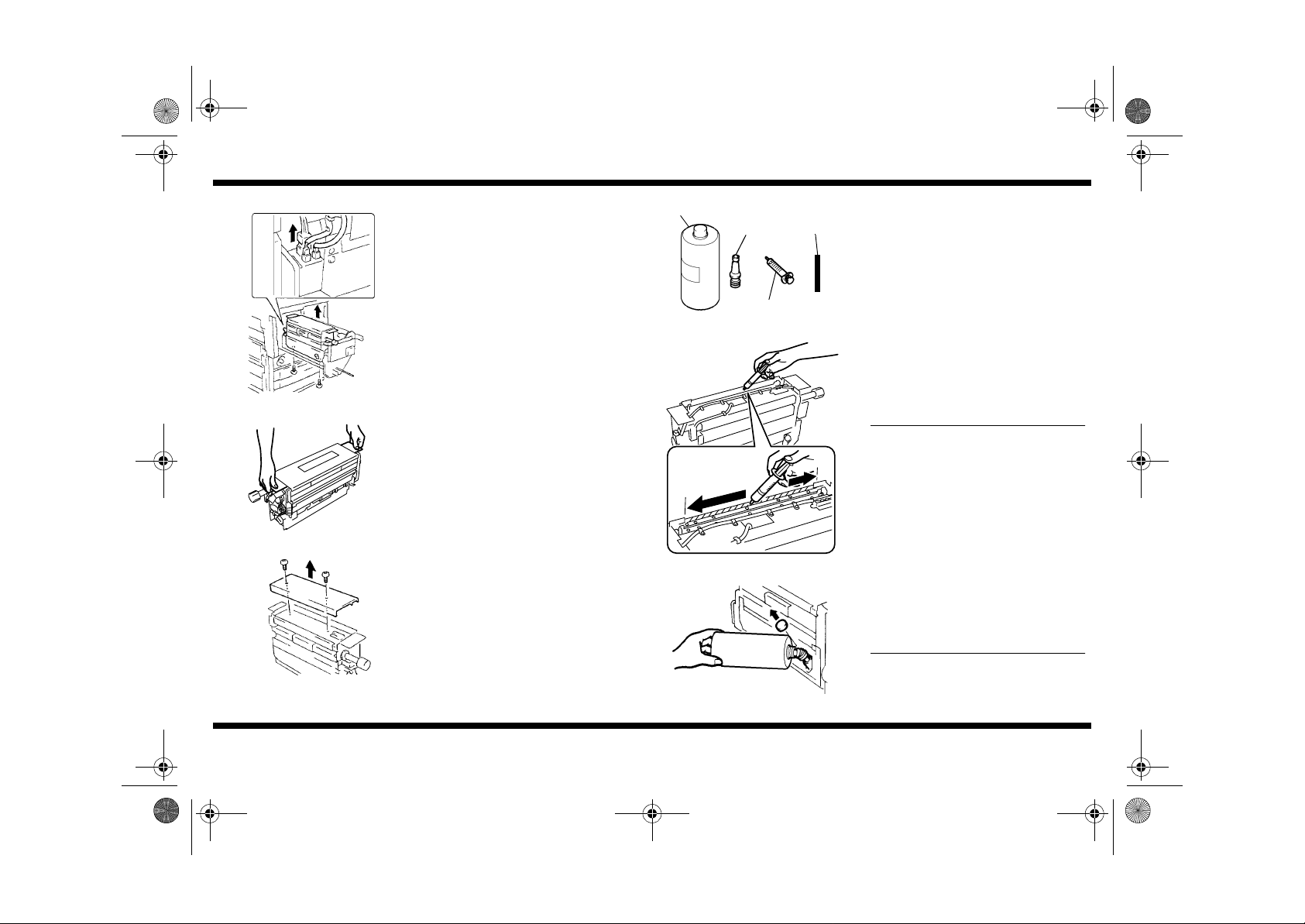
PREPARING THE FUSING UNIT
■
1. Unplug three connectors at the rear of the
Fusing Unit, remove 2 screws from
underneath the unit.
CF9001
Fusing Oil
Spout
Rubber
Tube
3. Gather th e can of oil (1 000ml ), sp out, sy ring e
and rubber tube from the accessories.
1144U102AA
1154U004AA
1144U103AA
1179-7744-03
Lift the unit out.
2. Remove the top cover of the fusing unit.
– 4 –
1154U066AA
1179U005AB
154U067AB
Syringe
4. Fill the syringe with 10ml of oil and inject it
into the fusing unit just inside the right side of
the unit between the cover and the blade
assy. Repeat with 10ml more. (Only use a
total of 20ml of oil.)
•
Only inject the oil into the space between
the cover and blade assy, not on the
blade, not over the upper roller, not over
the front and rear gear areas.
•
Be sure to inject the oil evenly.
•
Let nothing (dust, lint, hair, etc.) fall into
the Fusing Unit to contaminate it.
•
If setting up the copier at the workshop,
do not fill the fuser oil bottle until the
copier is moved to the user’s premises. In
order to make test copies at the
workshop, inject oil into the fuser as
described in step 4 above. 30ml of oil
makes about 20 copies. Inject more oil as
needed for testing purposes.
5. Remove the cap of the fuser oil bottle. Attach
the spout to the oil can and pour the oil into
the fuser oil bottle. Recap the fuser oil bottle.
Page 6
NOTE
1179-7744-03.fm Page 5 Thursday, November 9, 2000 1:47 PM
CF9001
1154U006AA
1144U104AA
NOTE
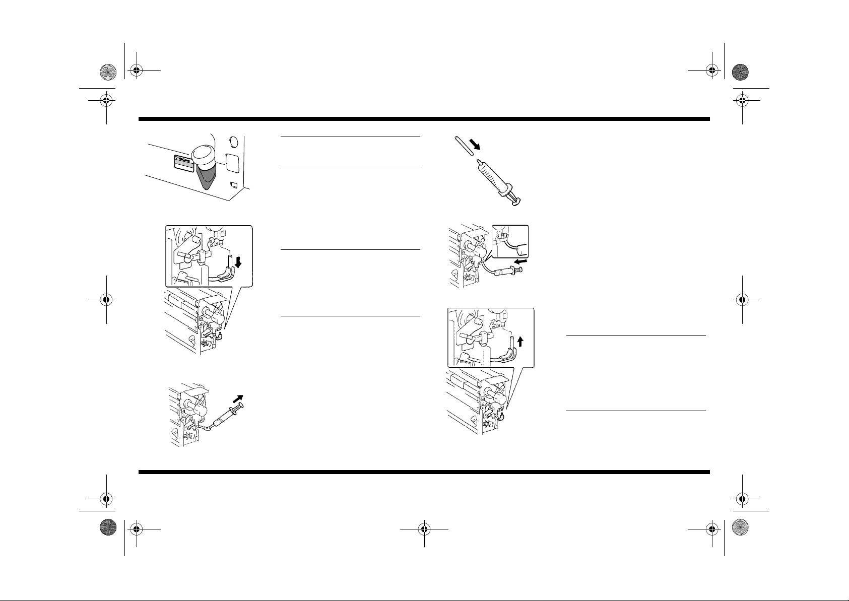
Pour the oil no higher than the Max. Level
Inicator on the Fusing Unit.
6. Leaving the valve in place, pull off the lower
tube from the Oil Pump Assy.
NOTES
•
Hold the valve when pulling the tube off or
the valve will come off with the tube.
•
Before pulling the tube and drawing the
oil, place a paper towel underneath the
pump section to catch any priming oil
leaking from the pump.
7. Insert the syringe into the tube and draw
about 5ml of oil from it.
8. Attach the rubber tube from the accessories
box to the syringe.
1144U106AA
9. Attach the tube to the lower end of the pump
and inject the 5ml of oil into it.
1179U006AB
10.Remove the tube and syringe, and plug back
in the lower tube of the Oil Pump Assy.
Do not turn any of the knobs, gears or
rollers of the Fusing Unit when the oil tank
is empty. The pump is primed with oil at
the factory. If anything is turned in the unit
when the tank is empty, the pump will lose
its priming oil and may not be able to pump
afterwards.
1144U105AA
1179-7744-03
1144U108AA
– 5 –
Page 7
NOTE
1179-7744-03.fm Page 6 Thursday, November 9, 2000 1:47 PM
CF9001
1144U109AA
1144U110AA
1144U086AA
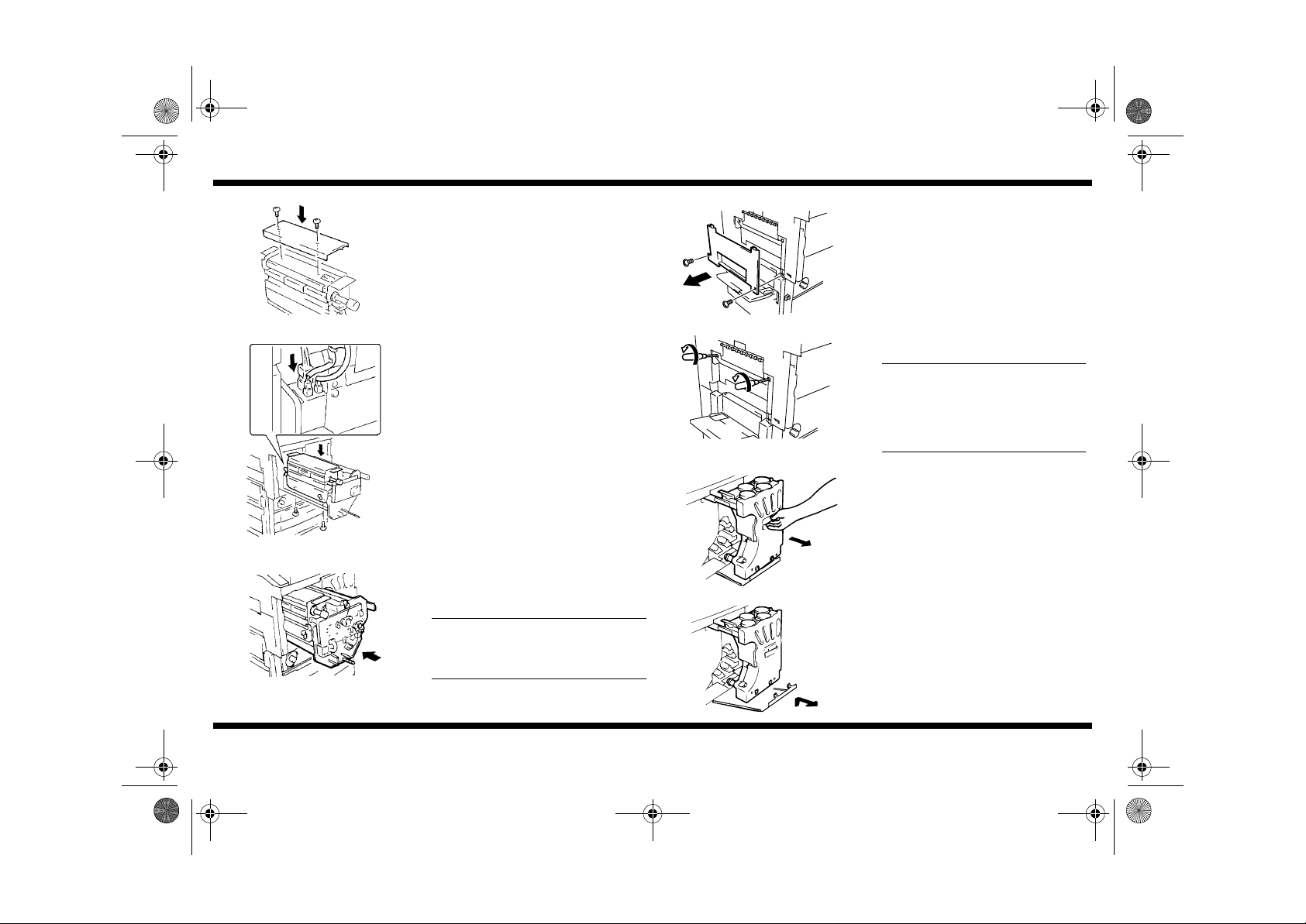
11.Resecure the top cover.
12.Reinstall the unit with 2 screws and plug in
the 3 connectors.
13.Push the Transfer Drum Unit back into the
copier.
NOTE
Make sure the lock lever is in the unlocked
position when pushing the Transfer Drum
Unit into the copier.
1154U007AA
1154U008AA
TONER LOADING
■
1179N008AA
14.Open the manual feed table and remove the
Left Middle Cover from the copier.
15.Insert a screwdriver through the holes and
screw in the two Hexagonal Bolts (front and
rear) alternately until they are completely
tightened. Then loosen each Bolt four full
turns.
When backing off the bolts, do that in two
separate sequences by loosening each
bolt two turns each (at the front and rear)
alternately to achieve a uniform nip
width.
1. Pull out the Hopper Unit.
2. Remove the Toner Antispill Plate from the
bottom of the Hopper Unit.
1179-7744-03
1179N009AA
– 6 –
Page 8
1179-7744-03.fm Page 7 Thursday, November 9, 2000 1:47 PM
CF9001
1179U007AB
1144U115NA
1144L079AB
3. Loosen the 2 screws securing the Hopper
Unit and remove it.
NOTE
Be careful, the Hopper Unit is heavy.
4. Push the hopper rails back into the copier.
NOTE
Whenever the Toner Hopper is removed
from the copier, cover the exposed ports.
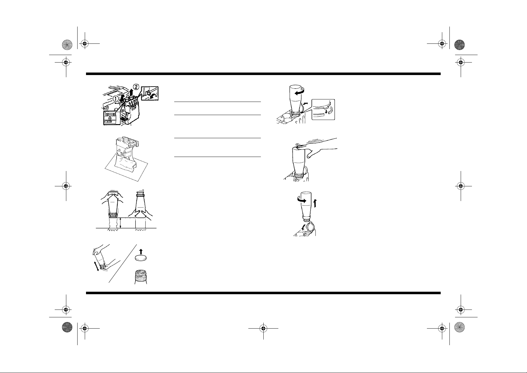
5. Sharply tap the toner bottle 5 times (from
about 10cm) on a hard surface.
Then turn it over and repeat.
6. Hold the bottle of toner as illustrated and
shake it vertically more than ten times. Then
remove the cap from the bottle.
7. Making sure not to pour the color toner into
the wrong hopper, set the upturned bottle
onto the hopper opening and turn clockwise
until it is secure.
1144U112AA
8. Tap the bottle to ensure complete emptying.
1144U113AA
9. Turn the bottle counterclockwise, remove it,
and close the lid of the hopper.
Repeat the same procedure for all 4 color
toners.
1144U114AA
1144L078AB
1179-7744-03
1179N011AA
– 7 –
Page 9
1179-7744-03.fm Page 8 Thursday, November 9, 2000 1:47 PM
PC DRUM INSTALLATION
■
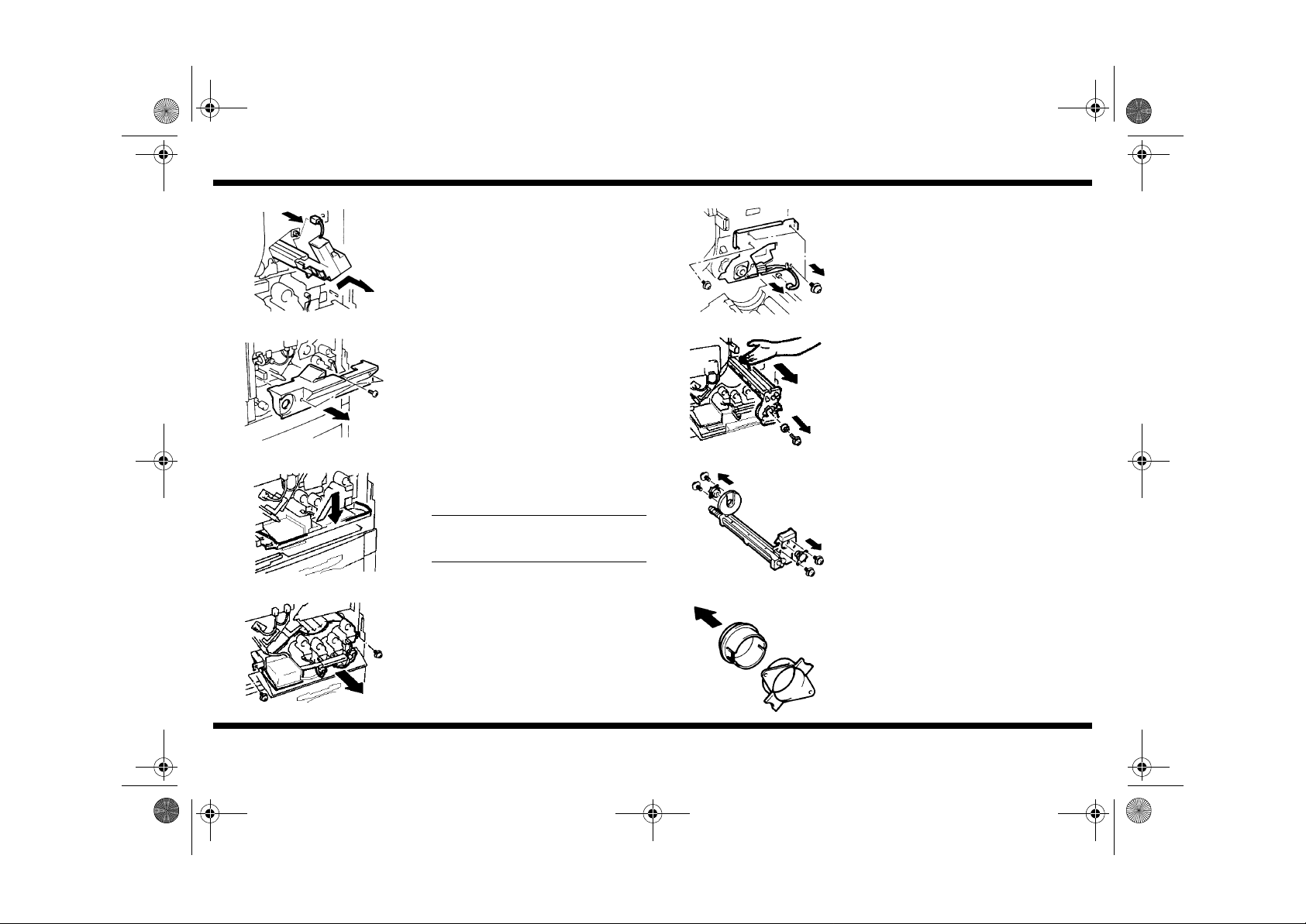
1. Unplug and pull out the Drum Charge
Corona Unit.
CF9001
5. Unplug the connector, remove 4 screws,
carefully remove the PC unit front flange.
1179U008AB
1144U026AA
1179U081AA
1179U086AA
1179-7744-03
2. Remove 3 screws and the Developer Unit
Cover.
3. Pull the Lock Release Lever handle up and
out, then push down.
NOTE
Make sure the upper drawer is closed
before operating the lock release lever.
4. Remove 2 screws and pull out the developer
unit a short distance.
1144U030KA
6. Remove the fixing screw and the Drum
Holder from the PC unit. Remove the PC
unit from the copier.
1179U083AA
7. Remove 2 screws and the packing holders
from the front and rear of the PC drum unit.
1144U033AA
8. Separate t he pa cki ng c olla rs ( blac k) fr om th e
holders.
1144U034AA
– 8 –
Page 10
a
Cleaning
Blade
Toner
PC Drum
1179-7744-03.fm Page 9 Thursday, November 9, 2000 1:47 PM
CF9001
1144U035AA
1144U036AA
1144U037AA
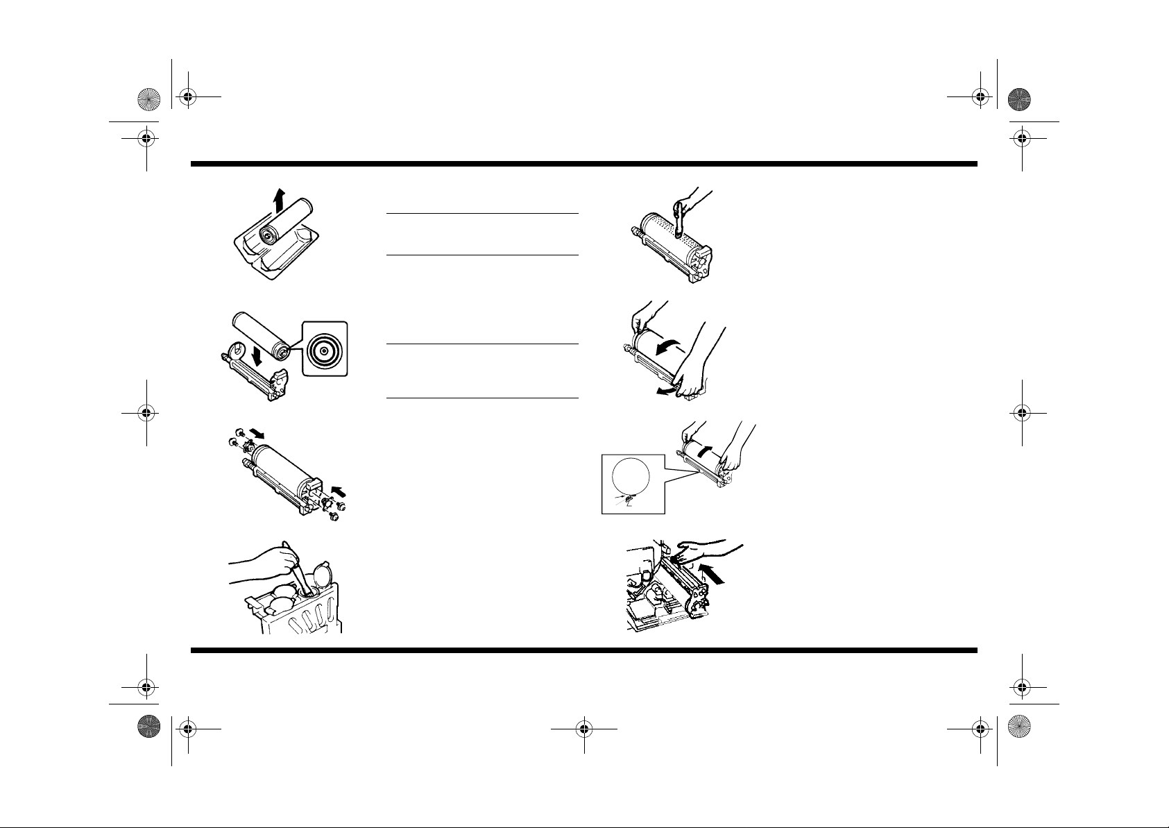
9. Unpack the PC drum.
NOTE
Do not touch the PC Drum surface with
your bare hands.
10.Install the PC Drum with the end having the
copper rings facing the front.
NOTE
Double-check that the PC Drum is installed
in the correct direction (copper rings to the
front).
11.Resecure the holders to the front and rear.
12.Dip a brush into one of the toner hoppers.
Any color toner will do.
1144U039AA
1144U040KA
1144U041NA
13.Apply a light coating of toner along the top of
the drum.
14.Unlocking the Cleaning Blade with the left
hand, grasp the edge of the drum with the
right hand and turn the drum
counterclockwise until the toner along the top
of the drum reaches the Cleaning Blade.
15.Lock the Cleaning Blade, grasp the drum by
the edges and turn the drum clockwise 3 full
turns. Afterwards, check area "a" to see if
any toner has fallen onto the Cleaning Blade.
If so, wipe the Blade.
Afterwards, check that the drum turns
smoothly.
16.Check to see the Transfer Drum and
Developing Unit are installed in the copier
and make sure their Lock Levers are in the
unlocked position. Carefully reinstall the PC
Drum Unit on the rail inside the copier.
1144U038AA
1179-7744-03
1179U084AA
– 9 –
Page 11

NOTE
1179-7744-03.fm Page 10 Thursday, November 9, 2000 1:47 PM
CF9001
1154U009AA
1179U085AA
OK
1154U010AA
X
Slide the PC Drum Unit along the rail.
Caution!
While sliding the unit into the copier, swing
the drum to the left to avoid scratching it on
a drum sensor and the Toner Scattering
Prevention Seal.
17.Check that the PC Drum Unit is correctly
installed.
1144U044AA
1179U009AA
Brass
1144U046KA
If the unit cannot be pushed all the way into
the copier, insert the PC drum key and turn
clockwise about 1/4 turn, then test the Unit
by pushing it in. Repeat this procedure until
the unit slides into place.
18.Attach the spring and Drum Holder with a
fixing screw.
Be careful to avoid the spring's recoil while
securing the Drum Holder.
19.Carefully refit the PC Unit front flange. First
reset the 3 black screws, then the brass
screw. Plug in the connector.
Black
20.Reinstall the Drum Charge Corona and plug
it in.
1179-7744-03
1154U011AA
1179U010AB
– 10 –
Page 12

NOTE
1179-7744-03.fm Page 11 Thursday, November 9, 2000 1:47 PM
STARTER LOADING
■
1. Pull out the Developing Unit.
2. Cover the exposed sleeve/magnet roller area
with the Mag Roller Shields.
NOTE
Do not permit any contamination of the
1179U088AA
sleeve/magnet rollers.
3. Plug in the single connector of the jumper
harness to the left of the unit, the two
connectors to the left at the rear of the unit.
1154U012AA
View from above.
CF9001
1144U053AA
1154U014AA
1179N003AA
1179N004AA
ON
4. Remove 1 screw and black toner feed chute.
The colors are in the order from left to right :
black, cyan, magenta, yellow.
5. Attach the starter chute.
6. With the front door open and no interlock
switch jig set, plug in the power cord and turn
ON the main switch.
The front door must be open before the
copier is turned ON.
1154U013AA
1179-7744-03
7. When the "The sectio n indicated by → is
open" warning appears on the display, press
the keys Stop → 0 → Stop → 2 to access the
Developer Change Mode.
1179P001CA
– 11 –
Page 13

NOTE
1179-7744-03.fm Page 12 Thursday, November 9, 2000 1:47 PM
CF9001
1144U063AA
1179P002CA
1179P003CA
8. With the Developer Change Mode Menu on
the display, insert the front door interlock
switch jig.
9. Touch "Developer Change."
10.Touch "Ex."
11.Touch “Black.”
Select the color of the starter to be loaded.
12.Press the Start key.
Developer activity will begin.
1179N005AA
13.Pour the starter i nto the replenishing port.
Make sure that the correct color of starter
is loaded in the correct developing unit.
1179U017AA
14.Empty the entire contents of the bottle and
press the Stop key.
Repeat step 5, 11-14 for each color starter.
15.When all 4 color starters have been loaded,
touch "Ex."
1179P004CA
1179-7744-03
1179P004CA
– 12 –
Page 14

NOTE
1179-7744-03.fm Page 13 Thursday, November 9, 2000 1:47 PM
STARTER AGITATION
■
16.Touch "On" for all four color starters and
press the start key to begin agitation.
When the activity is completed it will stop
automatically.
CF9001
20.Remove the starter chute.
1179P006CA
Pre-Image
Transfer
Charge
179U091AA
1179N007AA
1179U090AA
1179-7744-03
OFF
AIDC Sensor
17.After agitating all 4 color starters in the
Developer Mixing Chamber, clean the AIDC
sensor and the Pre-Image Trans fer Charge
section if they are dirty.
18.Turn OFF the main switch and unplug the
power cord.
Turn OFF the front door interlock switch.
19.Remove the mag. roller shields.
1154U015AA
21.Reinstall the toner feed chute.
When the toner chute is seated, press it
downward while securing it with a screw to
prevent toner dust leakage.
1144U057AA
22.Unplug the jumper harness.
Please keep the Jumper Harness for future
use.
1144U058AA
23.Push the developer unit back into the copier
and secure with the 2 screws.
1179U087AA
– 13 –
Page 15

1179-7744-03.fm Page 14 Thursday, November 9, 2000 1:47 PM
CF9001
1179U082AA
1154U016AB
ATDC/AIDC LEVEL ADJUSTMENT
■
1144U091AA
ON
1179N003AA
24.Firmly pull up on the developer lock release
lever and push the handle in.
25.Slide the lever as shown on the left.
1. Reattach the Transfer Unit lock lever and
lock the unit into position.
2. Plug in and turn ON the copier.
NOTE
At this time, make sure the front door
interlock switch is OFF
3. When the warning appears on the display,
press the keys Stop-0-S top-2 (in that order)
to enter the Developer Change mode.
1179P001CA
4. Turn ON the front door interlock switch.
1144U063AA
5. Touch "After Dev. (C/M/Y/BK) has been
changed."
1179P002CA
6. Touch "On" for all three colors.
1179-7744-03
1179N004AA
1179P007CA
– 14 –
Page 16

1179-7744-03.fm Page 15 Thursday, November 9, 2000 1:47 PM
CF9001
1179N005AA
1179P508CA
1179P009CA
7. Press the Start key to adjust the ATDC.
8. The activity will automatically stop when the
adjustment is completed.
Check that the adjustment result has been
OK. Then touch "ON" for Enter Ref. Value on
the ATDC Sensor Adjust (Auto) screen and
touch "Ex."
9. When the AIDC Sensor Adjust (Auto) screen
appears, press the start key.
When the activity is completed it will stop
automatically.
10.Check that the adjustment result has been
OK. Then, on the AIDC Sensor Adjust (Auto)
result screen, touch "Ex."
11.When the "AIDC offset" screen appears,
press the start key.
It will stop when the activity is completed.
1179P511CA
12.Touch "Ex."
1179P511CA
13.Press the start key when the "Black ATDC
Adjust" screen appears.
The "Black ATDC Adjust" runs for about
5 min. and will stop automatically. Touch
"Ex." and turn OFF the copier.
1179P012CA
14.Access the Tech. Rep. Mode screen. (Refer
to the Service Manual for the procedure.)
15.Touch “State Confirm.”
1179P010CA
1179-7744-03
4605P001CA
– 15 –
Page 17

1179-7744-03.fm Page 16 Thursday, November 9, 2000 1:47 PM
CF9001
1179P042CA
1179P045CA
1179P044CA
1179-7744-03
16.Touch “Bk Toner Sup. Status.”
17.Check that the values for “Dev. Constant” are
not “0.”
NOTE
If the Bk Developing Unit is defective, all
values for “Dev. Constant” are “0.”
If any of the “Dev. Constant” value is “0” :
Check the value for η of “PC Dev. Status.”
If the value for η is correct (η ≠ 99, η <
10000), carry out “Bk Toner Sup. Status”
again.
If the value for η is not correct, replace the
Bk Developing Unit, then make the check
again.
18.Touch “Ex.” and turn OFF the copier.
1179P044CA
19.Turn OFF the front door interlock switch.
1144U063KA
20.Install the Developer Unit Cover with 3
screws.
1144U026AA
21.Pull out the hopper rails and install the Toner
Hopper (secured by 2 thumb screw s).
Reattach the Toner Antispill Plate to the
bottom of the Hopper Unit and close the front
door.
1179N010AA
– 16 –
Page 18

1179-7744-03.fm Page 17 Thursday, November 9, 2000 1:47 PM
FUSER NIP LEVEL ADJUSTMENT
■
ON
1. Turn ON the copier.
At this time, make sure the front door is
closed.
CF9001
6. When the Start key changes from orange to
green, press the Start key.
1179N004AA
4605P001CA
4605P005CA
1179U012AA
1179-7744-03
2. Access the Tech. Rep. Mode screen. (Refer
to the Service Manual for the procedure.)
3. Touch "Machine Adjust 1."
4. Touch "Fuser Nip."
5. Place an A4(C) or Letter(C) size sheet of
paper crosswise into the drawer set for that
size.
– 17 –
1179N005AA
1179N020AA
1154U008AA
7. Measure the width of the stripe at points near
the front and rear edges. If should fall within
the following range.
Further, subtract the measurement taken at
the front from the measurement in the rear
(or vice versa) to check that the difference
between the two meets the specifications
given below.
<Specifications>
Fusing nip width (at the center): 8.5 ±0.3mm
Difference: Within 0.5mm
If the width measurements of the stripe on
the test print deviate from the given target
values, adjust the pressure bolts on the
fusing unit.
If > 6.3mm, loosen the pressure bolts.
If < 5.7mm, tighten the pressure bolts.
Make one more test print.
Page 19

1179-7744-03.fm Page 18 Thursday, November 9, 2000 1:47 PM
8. When the adjustment is completed, touch
"Ex."
1179P013CA
CF9001
1179-7744-03
– 18 –
Page 20

1179-7744-03.fm Page 19 Thursday, November 9, 2000 1:47 PM
FUSER SPEED LEVEL ADJUSTMENT 1
■
1. Load A3 or Ledger-size paper in the drawer
set for that size.
Open the Front Door and turn ON the
interlock switch.
CF9001
5. During the copy run, check the paper loop
between the Transfer Drum and Fusing
Roller.
1179U013AA
4605P005CA
1179P014CA
1179N005AA
1179-7744-03
2. Touch "Fuser Speed."
3. Touch "CF paper 120mm/s" and make an A3
or Ledger si ze copy.
4. Press the Start key. A half-tone test print will
be produced.
– 19 –
1154U023AA
1154U050AB
1154U051AB
1179P014CA
Paper Loop
Transfer
Drum
Paper Loop
Transfer
Drum
<The fuser speed is normal>
<If the fuser speed is too fast>
The paper is pulled by the Fusing Rollers,
preventing a paper loop from forming and
causing the paper to straighten.
Decrease the fuser speed by touching the
Down key until the loop is correctly formed.
Page 21

1179-7744-03.fm Page 20 Thursday, November 9, 2000 1:47 PM
1154UI052AB
Paper Loop
Transfer
Drum
Paper Loop
<If the fuser speed is too slow>
The paper is pushed by the Transfer Drum,
creating a large upward or downward loop.
CF9001
IF THE TEST PRINT CONTAINS ABRASIONS OR STRESS MARKS,
■
PERFORM THE FOLLOWING PROCEDURE.
1. If stress marks are at the front of the page,
loosen the front pressure bolt. If abrasions
are at the front of the page, tighten the front
pressure bolt.
Do not adjust the rear pressure bolt.
abrasion
1154U053AA
stress marks
2. If stress marks are at the rear of the page,
tighten the front pressure bolt. If abrasions
are at the rear of the page, loosen the front
pressure bolt.
1154U019AB
1179P014CA
abrasion
1154U053AA
1179-7744-03
Transfer
Drum
stress marks
Increase the fuser speed by touching the Up
key until the loop is correctly formed.
6. Check the test print for copy quality.
Do not adjust the rear pressure bolt.
1154U008AA
FUSER SPEED LEVEL ADJUSTMENT 2 (Fine Adjustment)
■
Since repeatedly adjusting the nip level an d
fuser speed may leave abrasions or stress
marks in the test print, tighten both the front
and rear pressure bolts of the Fusing Unit,
then start from the "FUSER NIP LEVEL
ADJUSTMENT" and perform the adjustment
again.
When the adjustment is completed, touch
"Ex." twice.
(a) Solid black adjustment
1. Load A3 or Ledger-size paper in the drawer
set for that size.
Open the Front Door and turn ON the
interlock switch.
1179U013AA
– 20 –
Page 22

1179-7744-03.fm Page 21 Thursday, November 9, 2000 1:47 PM
CF9001
4605P001CA
1179P036CA
1179P037CA
2. Touch "Test Print."
3. Touch "Halftone."
4. Touch "4 Color."
5. Press the Clear key and enter "200."
1179N005AA
1154U050AB
1154U052AB
Oil Tank
Oil Tank
Paper Loop
Transfer
Drum
Paper Loop
Transfer
Drum
6. Press the Start key.
*Following the same procedures as in FUSER
SPEED LEVEL ADJUSTMENT 1, check the
loop formed in the paper.
<The fuser speed is normal>
The loop in the paper does not touch the
bottom of the oil tank.
<If the fuser speed is too slow>
The loop in the paper bulges upward to tou ch
the bottom of the oil tank.
Increase the fuser speed by touching the Up
key so that the loop does not touch the
bottom of the oil tank.
Decrease the fuser speed by touching the
Down key until the loop is correctly formed.
1179P039CA
1179-7744-03
1179P014CA
– 21 –
Page 23

NOTE
1179-7744-03.fm Page 22 Thursday, November 9, 2000 1:47 PM
CF9001
(b) Blank sheet adjustment: Only when the speed has been changed in
(a) Solid black adjustment
"
1179U013AA
4605P001CA
1179P036CA
"
1. Load A3 or Ledger-size paper in the drawer
set for that size.
Open the Front Door and turn ON the
interlock switch.
2. Touch "Test Print."
3. Touch "Halftone."
4. Check that "Cyan" is selected.
1179P039CA
1179N005AA
1154U051AB
Oil Tank
Paper Loop
Transfer
Drum
5. Press the Clear key.
6. Press the Start key.
*Check the loop in the paper once again.
<The fuser speed is normal>
The loop in the paper does not touch the
bottom of the oil tank.
Decrease the fuser speed by touching the
Down key so that the loop does not touch the
bottom of the oil tank.
1179P037CA
1179-7744-03
– 22 –
1179P014CA
Using the same procedures, make only
FUSER SPEED LEVEL ADJUSTMENT
1 for "Thick Paper 1" and "OHP Film.
"
Page 24

1179-7744-03.fm Page 23 Thursday, November 9, 2000 1:47 PM
7. Reattach the Left Middle Cover to the copier.
1154U062AA
8. Reattach the Transfer Unit Cover, knob M9
and M4 lock lever.
1154U068AA
CF9001
1179-7744-03
– 23 –
Page 25

1179-7744-03.fm Page 24 Thursday, November 9, 2000 1:47 PM
GRADATION ADJUSTMENT
■
1. Turn OFF the front door interlock switch and
close the front door. Touch "Gradation
Adjust."
Touch "Gradation Adjust."
CF9001
4. Place the gamma test pattern onto the
original glass with the corner mark in the
corner indicated on the original glass.
(Follow the instruction on the display of the
Touch Panel.)
4605P001CA
1179P541CA
1179U013AA
1179N005AA
1179-7744-03
2. Place an A3 or Ledger size sheet of paper
into the drawer set for that size.
3. Press the Start key to produce a gamma test
pattern.
– 24 –
1144U074AA
1179N018AA
4605P001CA
1179N005AA
5. Cover the test pattern with 10 Sheets of
blank, white A3 or Ledger size paper and
close the Original Cover.
6. Press the Start key to read the gamma test
pattern. The test pattern doesn’t print out at
this time.
1179N005AA
7. When this step is completed, the Service
Mode Menu will reappear.
Touch "Gradation Adjust."
8. Press the Start key to produce another test
pattern. Repeat steps 4-8 two more times
using the latest produced test pattern each
time.
Page 26

1179-7744-03.fm Page 25 Thursday, November 9, 2000 1:47 PM
9. After “Gradation Adjust” has been
completed, check that the value for “Conv.
Value” falls within the reference value range.
Reference Value Range
High image density: 0±100
Low image density : 0±60
1179P541CA
If the value falls within the reference value
range, press the Panel Reset key and go to
“Image Quality Check” on the next page.
10.If the value falls outside the reference value
range, perform “Gradation Adjust” once
again and then check “Conv. Value.”
If the value falls within the reference value
range, press the Panel Reset key and go to
“Image Quality Check” on the next page.
1179P541CA
11.Press the Panel Reset key.
CF9001
1139U021BA
1179-7744-03
– 25 –
Page 27

1179-7744-03.fm Page 26 Thursday, November 9, 2000 1:47 PM
IMAGE QUALITY CHECK
■
1. Place the color chart on the original glass and make a copy.
2. Check for any streaks or voids in the halftone band.
Halftone Band
CF9001
3. If there are any streaks or voids, refer to the "Image Quality Problems" section in the Troubleshooting guide of the Service Manual.
1179-7744-03
– 26 –
Page 28

1179-7744-03.fm Page 27 Thursday, November 9, 2000 1:47 PM
MACHINE SETTING
■
1. Access the Tech. Rep. Mode screen. (Refer
to the Service Manual for the procedure.)
2. Touch "Setting 2."
CF9001
6. Set the paper size for each tray, then touch
"Ex."
4605P001CA
4605P002CA
1179P018CA
4605P002CA
1179-7744-03
3. Touch "Serial # Input."
4. Enter the serial number for the copier and
each installed option, then touch "Ex."
5. Touch "Paper Size."
– 27 –
1179P019CA
4605P002CA
1179N007AA
7. Select another mode according to your
needs.
When all settings are completed, touch "Ex."
8. Press the Panel Reset key and turn OFF the
copier.
OFF
Page 29

1179-7744-03.fm Page 28 Thursday, November 9, 2000 1:47 PM
CF9001
DRAWER SIZE CHANGE
■
1. Pull out the Drawer and remove the Side and
End Guide Plates.
1138U205A
2. Reposition the Side and End Guide Plates in
accordance with the size of paper being
used.
*Positions for the Side and End Guide Plates
are shown in the Table below.
1138U206A
Drawer Size Conversion Table
Paper Size
A5(T)/(L) 13 G 5-1/2 x8-1/2 (T)/(L) 14 H
B5(T)/(L) 11 K 8 x10⁻¹/2 (T)/(L) 10 L
A4(T)/(L) 9 O 10-1/2 x8 (Y)/(C) 3 F
A4(Y)/(C) 1 G 8 x13 (T)/(L) 10 Q
B4(T)/(L) 4 S 8-1/2 x11 (T)/(L) 8 N
A3(T)/(L) 1 U 11 x8-1/2 (Y)/(C) 2 H
Guide Plate
Side End Side End
Paper Size
8-1/2 x13 (T)/(L) 8 Q
8-1/2 x14 (T)/(L) 8 R
11 x14 (T)/(L) 2 R
11 x17 (T)/(L) 2
Guide Plate
CHECKING THE 1-SIDED IMAGE REGISTRATION
■
1. Pull out the Drawer and load the paper into it.
Close the Drawer.
1179U014AA
2. Turn ON the copier.
Access the Tech. Rep. Mode screen. (Refer
to the Service Manual for the procedure.)
3. Touch " Machine Adjust. "
4605P001CA
4. Touch " PRT Area. "
4605P005CA
5. Touch "Left Margin."
1179-7744-03
4605P006CA
– 28 –
Page 30

1179-7744-03.fm Page 29 Thursday, November 9, 2000 1:47 PM
6. Touch the key for the Tray that was changed.
Press the Start Key and make a test print.
CF9001
PAPER LOADING FOR DRAWERS
■
Pull out the Drawer and load the paper into it.
Close the Drawer.
1179P020CA
Feeding direction
1179N014AA
1179P020CA
1179-7744-03
7. Measure the width of the white margin along
the edge of the test print.
Tolerance A : 3
8. If the width deviates from the tolerance
value, adjust with the Up / Down keys.
Then make another test print.
If the range of deviation is within the
Tolerance, touch "Ex."
Press the Panel Reset key and turn OFF/ON
the copier.
1.5 mm
±
1179U014AA
AFFIXING THE LABELS
■
1179U015AA
DEHUMIDIFYING SWITCH CHECK
■
1179U016AA
– 29 –
Stick the Labels into the positions shown in
the illustration.
Check that the Dehumidifying Switch is
turned ON. If the switch is turned OFF,
please turn it ON.
Page 31

123
456
789
0C
NOTE
1179-7744-03.fm Page 30 Thursday, November 9, 2000 1:47 PM
CF9001
LIST OUTPUT
■
4605P001CA
1179P021CA
1179N019AA
1179N005AA
1179-7744-03
1. Access the Tech. Rep. Mode screen. (Refer
to the Service Manual for the procedure.)
2. Touch "List Output."
3. Touch "Image Processing."
4. Place a stack of 15 sheets of A4 or Letter
size lengthwise paper on the manua l feed
table.
5. Press the Start key to output the Machine
Data.
Do steps 3-5 for each List (Setting/Adjust,
Counter).
Please keep the output Machine Data.
Press the Panel Reset key and turn OFF/ON
the copier.
Date/Time Input Check
■
4458N001AA
1179P022CA
1179P022CA
1179N001AA
– 30 –
1. Press the f oll o wi n g ke y s on t h e c o ntr ol pa ne l
in this order to show "Date/Time Input" on the
screen.
(1) Stop key
(2) "1," "1," "4," and "4" of 10-Key pad
(3) Clear key
2. On the Date/Time Input screen, check the
"Present Date/Time."
If the date/time data is correct, touch "Ex."
3. If the date/time data is wrong, enter the
current correct time of day and date from the
10-Key Pad.
4. Touch "OK."
5. Touch "Ex."
When the Copier location is changed, the
Support Feet must be readjusted bef ore
use.
 Loading...