

Page 1

UNPACKING/SETTING-UP
INSTRUCTIONS
Fiery X3e / IF Kit G
For Product Code 1179
NOTE
•Keep all packing materials out of the r each of children.
•Before setting up, be sure to unplug the power cord of the copier.
1179-7792-01 Printed in Japan
Page 2
When mounting a Fiery X3e on the CF9001, be sure to install Interface Kit G.
Fiery X3e / IF Kit G
1179N559AA
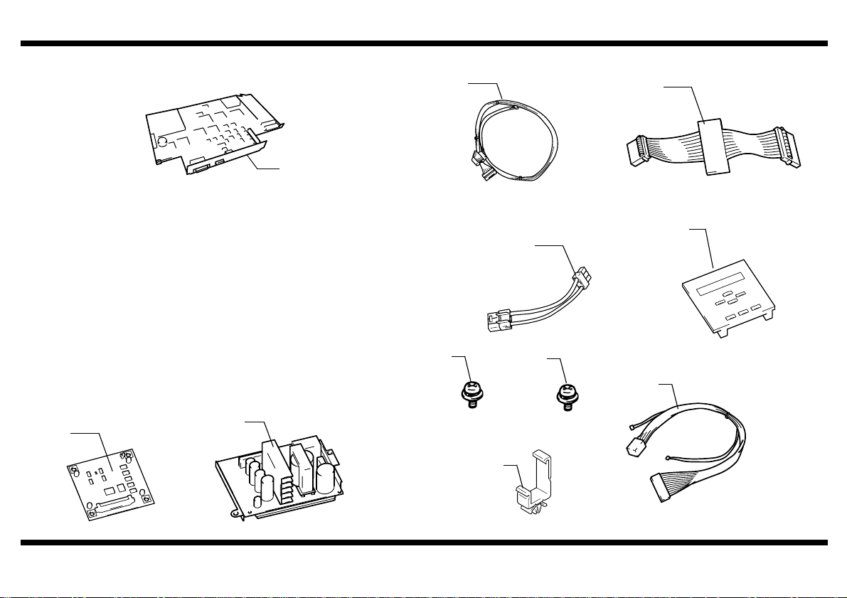
■ CONTENTS OF THE KIT
Check to see that the following items are contained in the Box.
1. Panel Board Assy....................................1
2. Power Supply Unit...................................1
3. Hookup Harness A ..................................1
4. Hookup Harness B ..................................1
5. Hookup Harness C..................................1
6. Control Panel fo r Built-in Controller.........1
7. Screw (3 x 6mm).....................................7
8. Screw (4 x 8mm).....................................4
9. Hookup Harness .....................................1
10. W ire Saddle.............................................2
1
2
Fiery X3e
3
1179U018AA
7
9739030613
1179U504AA
10
4
1179U019AA
6
5
1179U505AA
8
9
9646040813
1179-7792-01
1179U534AA
1179U501AB
1179N777AA
1179U540AA
–1–
Page 3
Fiery X3e / IF Kit G
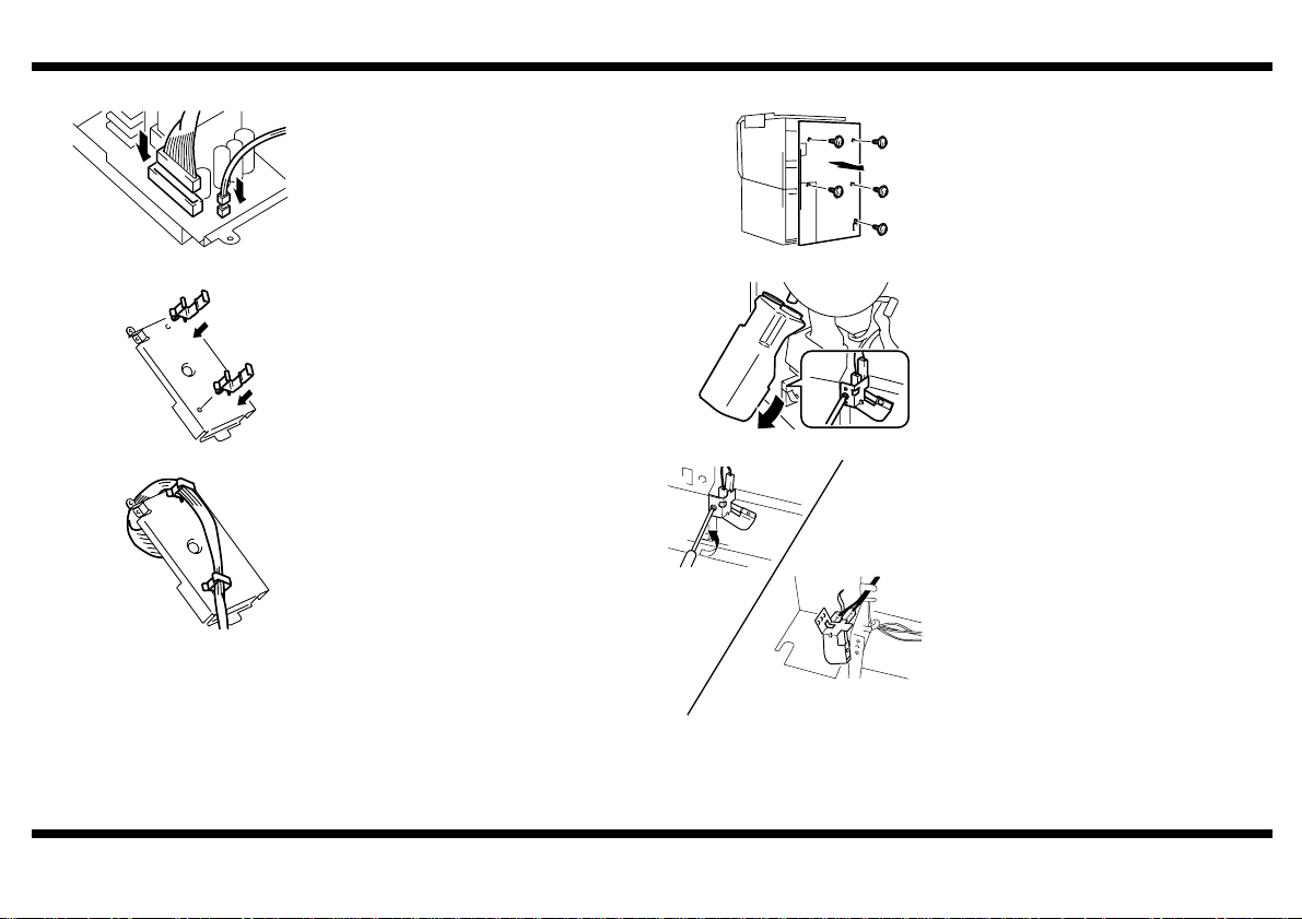
■ Positioning the Power Supply Unit ■ Installing the Power Supply Unit
1. Connect the Harness (at two places)
furnished with the kit to the PowerSupply
Unit furnished with the kit.
1. Remove the Rear Cover and Toner
Collecting Bottle Cover from the copier.
1179U537AA
1179U538AC
1179U539AC
1179-7792-01
2. Attach WIre Saddlesto the backsideof the
Power Supply Unit.
3. Place the other end of theHarness, whose
one end has been connected (at two places)
in step 1, into the Wire Saddles attachedin
step 2.
1179U506AB
2. Remove the Toner Collecting Bottle.
1179U535AA
3. Remove the Toner Collecting Bottle Set
Detecting Switch(one screw)and put itaside
as illustrated.
1179U020AA
1179U536AA
– 2 –
Page 4

Fiery X3e / IF Kit G
1179U507AB
1179U510AB
1179U509AC
4. Install the Power Supply Unit to the backside
of the copier at the location shown on the left.
Screw 4x8mm (three)
5. Connect the other ends of the harness of the
Power Supply Unit to the location shown on
the left.
6. Plug HookupHarness C to thePowerSupply
Unit and to the copier.
7. Place the TonerCollecting Bottleback to the
position.
8. ReinstallTonerCollecting BottleSet
Detecting Switch.
9. Reinstall the Rear Cover and Toner
Collecting Bottle Cover to the copier.
1179U510AB
■ Installing the Control Panel for Built-in Controller
1. Raisethe Original Cover and remove the
Upper Right Cover (two screws).
4460U001NA
2. Remove the RIght Cover (four screws).
1154U031AA
3. Open the Front Cover of the copier.
1179-7792-01
1179U511AB
– 3 –
Page 5

Fiery X3e / IF Kit G
1179U513AB
1179U514AB
1179U515AB
4. Remove the Upper Left Cover.
5. Remove four screws from the control panel
of the copier.
6. Unhook the tab at the front in the center of
the controlpanel. With care not to unplug
the connectoron the rightof the control
panel, turn over the control panel.
7. Unhook the four tabs at the top and bottom of
thec over for the built-in ontroller andremove
the built-in controllercover.
1179U517AB
1179U518AB
1179U519AC
8. Fitthe Control Panel for Built-in Controller
furnished with the Kit into position.
9. Turn over the control panel of the copier
again. Then plug Hookup Harness A
furnished with the kit to the Control Panel for
Built-in Controllerand secure the harness
with a cord clamp.
10.Bring the control panel of the copier back to
the original position and secure Hookup
Harness A in position using cord clamp that
are to be placed one after another starting
with the panel end.
11.Remo ve the Ferrite Core from the Control
Panel Harnessof the copier.
12.Secure the Control Panel Harness and the
Hookup HarnessA together with the Ferrite
Core.
13.Pass the two H arnesses throughthe Lock
Edge.11. Remove the Ferrite Core from th e
Control Panel Harness of the copier.
1179U516AB
1179-7792-01
– 4 –
Page 6

Fiery X3e / IF Kit G
1179U520AB
179U521AB
14.Reinstallthe controlpanel of the copier.
15.Reinstallthe Upper Left Cover.
■ Installing the Panel Board Assy
1179U523AB
1179U524AB
1179U525AB
1. Remove shieldcover D (three screws) and
shieldcover E (12Screws).
NOTE
A fan connector is plugged to the
backsideof shield cover D. Before
removing sheild cover D, be sure to
unplug this connector.
2. Remove shieldcover C (three screws).
3. Unplug all connectors from PWB-C so that
the Image Processing Box Assy can be
taken out.
4. Remove the Image Processing Box Assy
(two screws).
1179-7792-01
1179U526AB
– 5 –
Page 7

Fiery X3e / IF Kit G
1154U076AB
1179U527AB
1154U055AC
5. Remove shieldcover B fromthe Image
Processing Box Assy which has been
removed (eight screws).
6. Using the S crew s (four) furnished with the
kit,securethe Panel Board Assy furnished
with the kit to the Image Processing Box
Assy.
Screw 3x6mm (four)
7. Using the two screws used for shield cover
E, secure the Fiery X3e Board to the Image
Processing Box Assy in proper alignment
with the blue guide inside the assy.
8. Install shield cover B to the Image
Processing Box Assy (eight screws).
1179U528AB
1179U529AB
1179U530AB
9. Mount the Image Processing Box Assy to the
copier.
NOTE
Make sure that the harnesses on the
right and left and upper connectors
(three)are not wedged in the
mechanism.
10.Connect all connectors which have been
unpluggedin step3.
11.Using Hookup Harness B furnishedwith the
kit, connect the Panel Board Assy that has
been installed in step 6 with Fiery X3 e.
1154U075AC
1179-7792-01
– 6 –
Page 8

Fiery X3e / IF Kit G
1179U531AB
1179U532AB
1179U533AC
12.Connect Hookup HarnessA to theFiery X3e.
13. Install shield cover C (three screws).
NOTE
Make sure that harness are not wedged
in mechanism.
14.Fix the Fiery X3e Board to the shield cover D
using one screw used for shield cover E and
three screws (3x6mm) furnished with the kit.
15. Install shield cover D.
NOTE
• Do not forgetto connect the fan
connectron thebacksideof shield
cover D.
• Make sure that haarnesses are not
wedged in mechanism.
16. Install the Right Cover.
1154U088AA
17. Remove the ornament cover (three screws)
from the Right Cover.
1154U030AA
18.Install the Upper RIghtCover.
4447U054AA
1179-7792-01
– 7 –
 Loading...