

Page 1

P
P
rroodduucctt&
&
T
T
eecchhnnoollooggy
Efi Fiery
Calibration Manuals
y
Fiery XJ
Fiery X2
Fiery X2e
Fiery ZX
Fiery Z4
Page 2

Page 3

1-1 Managing color on the Fiery
1
Chapter 1:
Fiery Color
Management
The first part of this chapter describes the options available from the ColorWise color
management system and explains how you can customize the color settings for your
particular needs. It provides descriptions of the preset default settings of ColorWise
and covers additional options for users who need to customize ColorWise.
Beginning on page 1-13 is a detailed explanation of what a PostScript Level 2 or
PostScript 3 printer driver does, as well as information on the capabilities of various
printer drivers and instructions for setting color options with the PostScript drivers for
Windows NT 4.0, Windows 95/98, and Mac OS.
Managing color on the Fiery
There are three ways to modify the Fiery’s printing behavior:
• You can select ColorWise options for an individual print job using menus that
appear from the printer driver.
• You can select most ColorWise options as server defaults from Fiery Setup or from
the Control Panel, as described in the
to all subsequent print jobs unless you override them.
• You can select some ColorWise options, particularly default
and calibration options, from ColorWise Pro Tools. These options include default
Simulation Profile (see page 1-10), Simulation Method (see page 1-11), Appear in
Driver as (see page 4-7), default Source Profile (see page 1-8), RGB Separation (see
page 1-9), and associated calibration set (see page 3-3).
Configuration Guide
. These defaults will apply
ICC profile
settings
Applications can generate color data for the Fiery in many different
most common type of color data produced from office applications is RGB, while
prepress applications generally produce CMYK data. Desktop applications can also
generate spot colors such as PANTONE colors. To complicate matters, a single page
may contain a mix of RGB, CMYK, and spot colors. The Fiery lets users control the
printing of these mixed-color documents with features that apply specifically to RGB,
CMYK, or spot color data.
color spaces
. The
Page 4

1-2 Fiery Color Management
1
Fiery color management generates CMYK data to be sent to the copier; additional
processing may then be performed before printing begins.
The diagram below illustrates the print options in the Fiery color management process
that affect color data conversions. You access these print options when you send a print
job to the Fiery. Most of these options and settings are described in subsequent
sections of this chapter.
RGB data
CMYK data
Spot color data
RGB Source Profile
Gamma
Phosphors
White Point
Rendering Style (CRD)
Brightness
Pure Black Text/Graphics
Black Overprint
RGB Separation
Output profile
CMYK Simulation Profile
CMYK Simulation Method
Brightness
Pure Black Text/Graphics
Black Overprint
Combine Separations
Output profile
Spot Color Matching
Fiery
color
processor
Color data
sent to
copier
RGB Source Profile is the only color option that applies strictly to RGB color data.
The other options that affect RGB color also affect the more rarely used Lab, XYZ, and
other calibrated color spaces.
N
:
OTE
For users who are familiar with PostScript 3.0 color, all CIE-based ABC spaces
are affected. Also, if you send CMYK data to the Fiery in DEFG format, for example,
by choosing PostScript Color Management in Adobe Photoshop, options affecting
RGB data also affect this CMYK data.
Page 5
1-3 Managing color on the Fiery
1
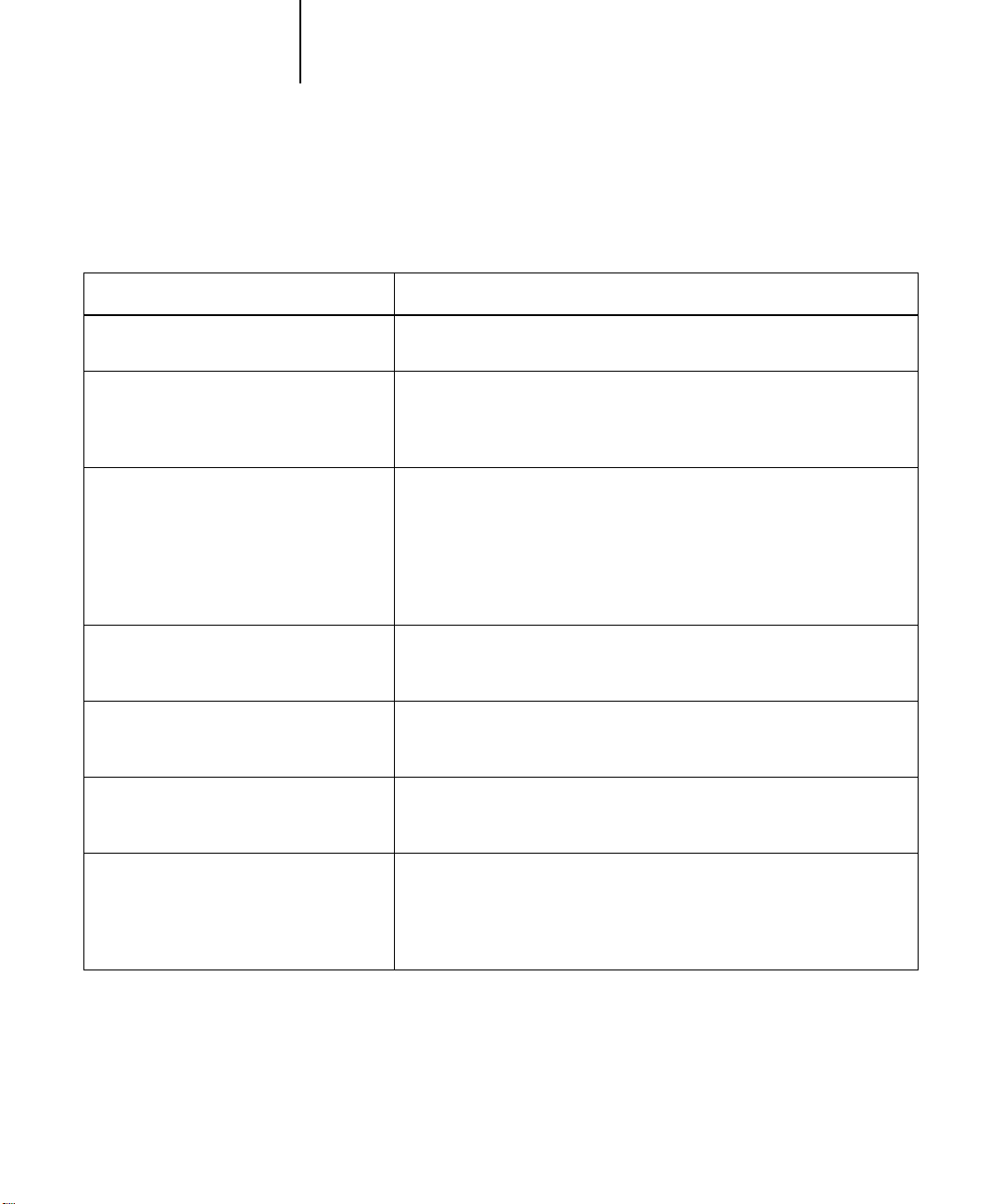
Settings for the following options can be specified via print options when you send a
job to the Fiery. Some can also be set as defaults by the administrator during Fiery
Setup. Settings specified via print options override the defaults.
Fiery color print option: What it does:
Brightness
85% Lightest to 115% Darkest
Rendering Style
Photographic/Presentation/Relative
Colorimetric/Absolute Colorimetric
(Default set at Setup)
RGB Source Profile
EFIRGB/sRGB (PC)/Apple Standard/Other/
Source 1–10/None
(Default set at Setup or with
ColorWise Pro Tools)
(Other) Gamma
1.0/1.2/1.4/1.6/1.8/2.0/2.2/2.4/2.6/2.8/3.0
(Other) Phosphors
Hitachi EBU/Hitachi-Ikegami/NTSC/
Radius Pivot/SMPTE/Trinitron
(Other) White Point
5000 K (D50)/5500 K/6500 K (D65)/
7500 K/9300 K
Performs a color adjustment on all
lighter or darker.
Applies a Fiery color rendering style (CRD) to RGB data (see page 1-5), or to
any incoming data with a PostScript
CMYK.
Applies an RGB source space definition to RGB data (see page 1-8). If you
choose the Other setting, you can specify particular settings for gamma,
phosphors, and white point. See the corresponding options in this table. This
option, along with Gamma, Phosphors, and White Point, are the only
ColorWise options that effect
RGB data also affect other, less commonly used color spaces, such as CIELAB
or CIE XYZ.
Applies the specified
page 1-8). To use this print option, you must choose Other as the RGB Source
setting.
Applies the specified phosphor (monitor type) information to the RGB source
space definition (see page 1-8). To use this print option, you must choose
Other as the RGB Source setting.
Applies the specified white point value to the RGB source color space
definition (see page 1-8). To use this print option, you must choose Other as
the RGB Source setting.
gamma value to the RGB source space definition (see
color channels
source color space
strictly
RGB data. All other options that affect
to make the printed output
definition, including
RGB Separation
Output/Simulation
Determines which CMYK color space your original RGB data will be
separated into—CMYK for the copier (Output) or CMYK for a specified
simulation (Simulation) (see page 1-9). It is important to note that when RGB
Separation is set to Simulation, RGB colors are affected by CMYK Simulation
Profile and CMYK Simulation Method.
Page 6

1-4 Fiery Color Management
1
Fiery color print option: What it does:
CMYK Simulation Profile
SWOP-Coated/DIC/Euroscale/Simulation
1–10/Match Copy/None
(Default set at Setup or in
ColorWise Pro Tools)
CMYK Simulation Method
Quick/Full
(Default set at Setup or in
ColorWise Pro Tools)
Output Profile
default output profile/Output 1–10
(Default set at Setup or in
ColorWise Pro Tools)
Pure Black Text/Graphics
On/Off
(Default set at Setup)
Black Overprint
On/Off (Default set at Setup)
Spot Color Matching
On/Off
(Default set at Setup or with
ColorWise Pro Tools)
Adjusts CMYK color data to simulate an offset press standard or a custom
color gamut defined at your site. The Match Copy setting bypasses Fiery
calibration to match a copy made from the copier glass. Choosing None
bypasses simulation (see page 1-10).
N
OTE: Some of the Simulation settings have slightly different names depending
on the model of copier.
Quick simulation applies one-dimensional transfer curves that adjust output
density only. Full simulation applies colorimetric transformations that adjust
hue as well as output density (see page 1-11).
The Output Profile is applied to all data in the print job (see page 1-11). Userdefined output profiles can be downloaded to the Fiery with
ColorWise Pro Tools (see Chapter 4).
The On setting optimizes the quality of black text and line art output (see
page 1-6).
The On setting overprints black text placed on colored backgrounds; it
automatically activates the Pure Black Text/Graphics option (see page 1-7).
The On setting enables Fiery matching of PANTONE colors; Off instructs the
Fiery to match color output to a Pantone-specified CMYK combination (see
page 1-12).
More-detailed explanations of how these and other settings affect your print jobs are
provided in subsequent sections of this chapter.
Page 7
1-5 Managing color on the Fiery
1
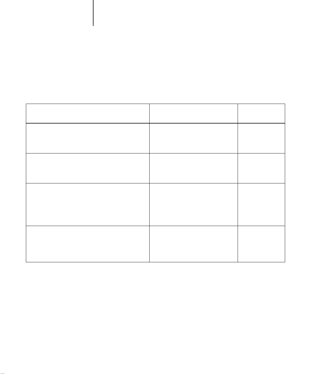
Rendering styles
The Rendering Style option specifies a CRD for color conversions. You can modify the
Rendering Style option to control the appearance of images, such as prints from office
applications or RGB photographs from Photoshop. The Fiery lets you select from the
four rendering styles currently found in industry standard ICC profiles.
Fiery rendering style: Best used for:
Photographic rendering typically results in less saturated
output than presentation rendering when printing outof-gamut colors. It preserves tonal relationships in
images.
Presentation—Creates saturated colors but does not
match printed colors precisely to displayed colors. Ingamut colors such as flesh tones are rendered well,
similar to the Photographic rendering style.
Relative Colorimetric—
transformation between the source and destination white
points. For example, the bluish gray of a monitor will
map to neutral gray. You may prefer this style to avoid
visible borders when not printing full-bleed.
Absolute Colorimetric—
transformation between the source and destination white
points. For example, the bluish gray of a monitor will
map to a bluish gray.
Provides white-point
Provides no white point
Photographs, including scans and
images from stock photography CDs.
Artwork and graphs in presentations.
In many cases it can be used for mixed
pages that contain both presentation
graphics and photographs.
Advanced use when color matching is
important but you prefer white colors
in the document to print as paper
white. It may also be used with
PostScript color management to affect
CMYK data for simulation purposes.
Situations when exact colors are
needed and visible borders are not
distracting. It may also be used with
PostScript color management to affect
CMYK data for simulation purposes.
Equivalent ICC
rendering style:
Image, Contrast,
and
Perceptual
Saturation,
Graphics
Same
Same
Page 8

1-6 Fiery Color Management
1
Pure Black Text/Graphics
The Pure Black Text/Graphics option affects the printout for black text and vector
graphics on a page. Under most circumstances it is preferable to leave this option set to
the On position. When Pure Black Text/Graphics is on, black colors generated by
applications are printed using 100 percent black-only toner (for example,
RGB = 0%, 0%, 0%; CMYK = 0%, 0%, 0%, 100%; or K = 100%). This means the
black text and line art will not exhibit halftone artifacts and will not be misregistered,
since there is only one toner used. In addition, this setting eliminates blasting. This
option is automatically set to On when the Black Overprint option is set to On.
For some jobs it is preferable to turn this option Off, for example, if the page includes
gradient fills that use black. The table below describes the behavior of the Pure Black
Text/Graphics option with black data defined in different color spaces.
NOTE: The Pure Black Text/Graphics option can be used only when printing
composites, not when printing separations.
Input
black color
RGB
CMYK
Prints 100% black
Spot
NOTE: PostScript applications, such as QuarkXPress, may convert elements defined as
RGB = 0%, 0%, 0% to four-color CMYK black before sending the job to the Fiery.
These elements are not affected by the Pure Black Text/Graphics option. See the
application notes for details. Also, black text and line art defined as RGB = 0%, 0%,
On Off
Pure Black Text/Graphics
With the default profile, prints a rich black
using all toners.
Prints only with black toner, because CMYK
simulations preserve the black channel. The
actual amount of toner used depends on the
current simulation and the calibration state of
the copier.
Prints only with black toner, because spot
color simulations preserve the black channel.
The actual amount of toner used depends on
the current simulation and the calibration state
of the copier.
Page 9

1-7 Managing color on the Fiery
1
0% in office applications (such as Microsoft Word) are converted to single-color black
(CMYK = 0%, 0%, 0%, 100%) by the Microsoft PostScript Level 2 driver for
Windows NT 4.0. To print this single-color black at the maximum toner density of the
copier, set the Pure Black Text/Graphics option to On.
Black Overprint
The Black Overprint option lets you specify whether or not black text, defined as
RGB = 0%, 0%, 0%, or as CMYK = 0%, 0%, 0%, 100%, overprints colored
backgrounds.
• On—Black text overprints colored backgrounds, eliminating white gaps and
reducing halo affects or misregistration of colors. Setting Black Overprint to On
automatically activates the Pure Black Text/Graphics option.
• Off—Black text knocks out colored backgrounds.
The Compression option must be set to On to use this option.
NOTE: PostScript applications may perform their own black overprint conversions
before sending the print job to the Fiery. See the application notes for details.
One example of how you might use this setting is with a page that contains some black
text on a light blue background. The background blue color is CMYK = 40%, 30%,
0%, 0% and the black text is CMYK = 0%, 0%, 0%, 100%.
• With Black Overprint On, the final text portions of the page are overprinted, or
combined with the underlying colors. This results in CMYK = 40%, 30%, 0%,
100% for the color used for the text. There is no transition in the cyan and magenta
toners, and the quality of the output is improved since it will not show artifacts near
the edges of the text. The option also works with text defined in the RGB color
space, that is RGB = 0%, 0%, 0%.
• With Black Overprint Off, the border of the text is on an edge that has cyan and
magenta toners on one side (outside the text) and black toner on the other side
(inside the text). On many copiers, this transition causes visible artifacts because of
the practical limitations of the copier.
Page 10

1-8 Fiery Color Management
1
RGB Source Profile
The RGB Source Profile setting allows you to define the characteristics of the RGB
data in your document so that the appropriate color conversion can occur on the Fiery.
Commonly used monitor color spaces are available from the driver and from the
ColorWise Pro Tools Profile Manager. In addition, for special needs you can use
ColorWise Pro Tools to download custom monitor or scanner profiles.
When you specify a setting other than None for the RGB Source Profile, the Fiery
overrides source color space definitions or profiles that other color management
systems may have specified. For example, if you specified a ColorSync System Profile
on your Mac OS computer, the RGB Source Profile setting overrides it. In cases where
you do not want this setting to override another specified source color space, choose the
None setting.
When you specify a setting other than None for the RGB Source Profile—since the
color space definitions are overridden—the prints from the Fiery will be consistent
across platforms. Below are the Fiery’s RGB Source Profile options.
• EFIRGB specifies an EFI-defined color space recommended for users who have no
detailed information about their RGB data.
• sRGB (PC) specifies the industry standard definition for a generic Windows PC
monitor.
• Apple Standard specifies the definition of all standard Mac OS computer monitors.
• Other allows you to specify custom RGB source settings. If you choose Other as the
RGB Source setting, you can choose settings for the Gamma, Phosphors, and White
Point options.
• Sources 1-10 specify the definitions you download as RGB source profiles. (For
more information about downloading RGB source profiles, see Chapter 4.)
If you are printing with the PostScript driver for Windows 95/98, the name of each
downloaded or custom profile is represented in the RGB Source Profile setting popup menu. If you are printing with the AdobePS driver from a Mac OS or
Windows NT computer, downloaded or custom profiles appear as Source 1 through
Source 10.
Page 11

1-9 Managing color on the Fiery
1
• None instructs the Fiery to allow the RGB sources you defined elsewhere, such as in
the application, to be used. When you set RGB Source to None, the appearance of
colors will not be independent of the file type. For example, RGB EPS files will look
different from RGB TIFF files.
With RGB Source set to None, PostScript RGB data that contains a source color
space definition is converted using the CRD specified by the Rendering Style option
(see page 1-5). NonPostScript RGB data and PostScript RGB data that does not
contain a source color space definition is converted using a general undercolor
removal conversion method.
RGB Separation
The RGB Separation option determines how RGB colors (as well as Lab and XYZ
colors) are converted to CMYK. The name of this option is meant to be descriptive,
since the option defines the color spaces that will be used by the Fiery to “separate” the
RGB data into CMYK values.
The two choices available for this option determine whether RGB data is converted
into the full gamut of the copier (Output) or whether it is first converted into the
gamut of another digital printer or a press standard (Simulation). This feature is
helpful for making one device behave like another for RGB data. For example, if a
high-quality ICC profile is available for another print device, the copier can simulate
the behavior of that device.
RGB Separation is also useful for prepress applications. For example, it lets you
experiment with the appearance of an RGB scan under different press printing
conditions without having to convert the RGB data to CMYK data for each printing
condition. When the desired printing condition is found, you can then convert the file
to CMYK, if desired, using the same CMYK simulation profile that was used during
the experimentation.
NOTE: The RGB Separation print option should be used in conjunction with the
Output Profile or CMYK Simulation Profile print options.
Page 12

1-10 Fiery Color Management
1
• Output converts all RGB colors into the CMYK color space of your copier (when the
Output Profile option is set to Printer’s default), or a customized CMYK color space
for your copier (when the Output Profile option is set to Output 1–10).
• Simulation converts all RGB colors into the CMYK color space for a specified
simulation (make sure to select the desired simulation with the CMYK Simulation
Profile print option).
CMYK Simulation Profile
The CMYK Simulation Profile print option allows you to print press proofs or
simulations. This setting specifies the offset press standard or other color printing
device that you want to simulate. This option affects CMYK data only.
On Windows 95/98, you can also view an unlimited number of custom Quick and
Full simulations created using ColorWise Pro Tools. On Windows NT and Mac OS
computers, you can view up to 10 Quick and 10 Full custom simulations. The number
of custom simulations is limited by the disk space on the Fiery.
NOTE: If you are printing with the PostScript printer driver on a Windows 95/98
computer, the name of each profile is visible in the pop-up menu for the CMYK
Simulation Profile setting. If you are printing with the AdobePS driver on Windows
NT or a Mac OS computer, custom simulations appear as Simulation 1 through
Simulation 10.
The CMYK Simulation Profile setting you should specify depends on the press
standard for which the CMYK data was separated.
• For images that were separated using a custom separation (such as a separation
produced with an ICC profile), choose the corresponding profile on the Fiery with
the CMYK Simulation Profile setting.
• For images that were separated for SWOP, choose SWOP as the CMYK Simulation
Profile setting.
Page 13

1-11 Managing color on the Fiery
1
NOTE: To properly simulate a printed image that was separated through the use of an
ICC profile, the same profile must be present on the Fiery. For more information
about downloading ICC profiles to the Fiery, see “Downloading profiles” on page 4-4.
• The Match Copy setting bypasses Fiery calibration to simulate the color of a copy
produced by the copier. Use this setting when you print images scanned with the
Fiery Scan plug-in set to Match Copy.
CMYK Simulation Method
The CMYK Simulation Method setting specifies the quality of simulation to perform.
• Quick applies one-dimensional transfer curves that adjust output density only.
• Full provides a more complete and accurate simulation by applying colorimetric
transformations that adjust hue as well as output density. The Full Simulation
option also maintains the integrity of the black channel by adjusting it
independently. This is especially important for images separated using an optimized
black generation (UCR/GCR) setting either from a scan or from within an
application such as Photoshop.
Output Profile
The output profile is applied to all data in the print job, so make sure the selected
profile is right for your job. The default output profile consists of both a profile for
your copier, describing the copier’s color characteristics, and a calibration target that
describes the expected behavior of the copier. In certain cases you may wish to
customize the default output profile to achieve particular color effects (see page 4-6). If
so, the new customized output profile is applied to all data in the print job.
NOTE: Changing only the output profile does not affect its associated calibration target
(since the target is based on a copier model). If you wish, you can edit D-Max values of
the calibration target separately (see page 4-6).
You can also use ColorWise Pro Tools to download your own output profile to the
Fiery (see page 4-4). Downloaded output profiles are at first associated with the default
calibration target. As mentioned above, you can edit calibration target D-Max values
separately.
Page 14

1-12 Fiery Color Management
1
Spot Color Matching
The Spot Color Matching option provides automatic matching of PANTONE colors
with their best CMYK equivalents.
• On—The Fiery uses its built-in table to generate the closest CMYK matches of
PANTONE colors your copier can produce. (New tables are generated when you
add new output profiles.)
• Off—The Fiery uses the CMYK equivalents defined by your application to print
PANTONE colors.
For jobs that include PANTONE spot colors, set Spot Color Matching to On unless
you are printing press simulations. In that case, set Spot Color Matching to Off and
choose the appropriate CMYK Simulation setting (see page 1-10).
NOTE: You can use the Spot Color Matching option only when printing composites,
not when printing separations.
Spot Color Matching and the PANTONE Coated Color Reference
The PANTONE Coated Color Reference (described on page 5-8) prints differently
depending on the Spot Color Matching setting.
• On—The Fiery uses its built-in table to generate the best matches of the PANTONE
colors that your copier can produce. The PANTONE number is printed below each
swatch.
• Off—The Fiery prints swatches using the CMYK values recommended by Pantone
(and used by applications that provide PANTONE color libraries). The CMYK
values used to generate the color, as well as the PANTONE number of the color, are
printed below each swatch. These CMYK values are printed through the selected
CMYK Simulation and Output Profile settings.
Page 15

2-1 Workflow concepts
2
Chapter 2:
Simple and
Advanced
Workflows
This chapter discusses color management workflows used in short-run color printing
as well as color proofing on the Fiery. It also gives examples of color management in
specific desktop applications and the interaction between those applications and
ColorWise color management.
Workflow concepts
The term “workflow” is used to describe the path a job follows from its creation in a
desktop application to final printed output. It is helpful to think of the following
categories when describing workflows:
• Short-run printing versus color proofing for eventual output on an offset press
• RGB, CMYK, and PANTONE color systems
• Desktop color management within an application versus color management on the
Fiery, along with the notion that different versions of desktop applications handle
color management differently. So it is important to pay close attention to the version
of a particular application when considering the workflows in this chapter.
Short-run printing versus color proofing
Short-run color printing refers to those jobs for which the Fiery is the final print
device. Printing jobs to the Fiery in preparation for printing on an offset press is
referred to as color proofing. Both types of Fiery print jobs use RGB, CMYK, and
PANTONE colors.
• For short-run jobs, bright, saturated colors are often desirable. These are achieved by
using the full range of colors available, referred to as the full gamut of copier, or
more simply copier CMYK. See “Advanced Workflows” on page 2-10 for short-run
printing examples.
• Offset jobs proofed on the Fiery require the printed colors to match those from
another set of CMYK printing conditions. Colors that are specified for an offset
press require CMYK simulation optimized for proofing on the copier. See Advanced
Workflows on page 2-10 for color proofing examples that simulate the gamut of
another digital printer or press standard.
Page 16

2-2 Simple and Advanced Workflows
2
RGB, CMYK, and PANTONE colors
Colors can be defined in several different color models, the most common being RGB,
CMYK, and the PANTONE color matching system. Each model requires a different
color conversion at the Fiery. These different color conversion workflows are explained
below.
• RGB source profiles and color rendering dictionaries are used to map RGB colors
through a device-independent color space to a destination space, either the full
copier gamut in a short-run printing workflow or CMYK simulation in a color
proofing workflow.
• CMYK colors are device-dependent. In a proofing scenario, colors specified in
prepress applications are adjusted so the Fiery copier’s gamut can simulate that of the
press. In a short-run printing workflow, specifying CMYK colors according to the
calibrated copier output eliminates the need for simulation during printing.
• PANTONE spot colors are special inks manufactured to run on an offset printing
press. Spot colors can be simulated using CMYK copier toners or process color inks.
Two basic workflows exist for printing PANTONE colors to the Fiery:
Spot Color Matching On instructs the Fiery to match the PANTONE spot color to
the output of the copier.
Spot Color Matching Off instructs the Fiery to match the copier output to a
PANTONE-specified process simulation. This CMYK combination is then printed
with the CMYK Simulation setting you choose, such as SWOP or Custom, and
CMYK Simulation Method set to Full.
Page 17

2-3 Workflow concepts
2
Desktop versus Fiery color management
A desktop color management system uses ICC profiles to convert colors from one
device gamut to the next (see Appendix B). Desktop color management systems
convert color data when it is passed from one application to another or when the job is
sent to the copier.
ColorWise uses standard ICC profiles to convert colors to the copier gamut or to
simulate other devices such as an offset printing press. ColorWise manages color
conversions for all users printing to the Fiery from Windows and Mac OS computers.
It lets users follow a simple workflow with minimal intervention using robust default
settings, while giving advanced users the control and precision they need.
The Fiery can intelligently manage the printed appearance of RGB, CMYK, and
PANTONE colors. You can let the Fiery manage color for most short-run color
printing jobs without adjusting any settings.
Managing most or all of your color on the Fiery can eliminate the potential for
undesirable color management-related conflicts, such as iterative color conversions and
inconsistent color. The Fiery applies global corrections to specific groups of RGB,
CMYK, and PANTONE colors to avoid such conflicts, and color conversions on the
Fiery are in most cases much faster than similar conversions on a host computer.
Finally, by sending RGB files instead of larger CMYK files from applications to the
Fiery, network traffic is minimized and jobs are generally printed more quickly.
Page 18

2-4 Simple and Advanced Workflows
r
2
Simple workflows
Every time you print a document containing colors that were not chosen for your
specific copier, those colors need to be converted, which requires color management.
There are many places where color management can take place. Since ColorWise is
compatible with most other color management systems, you can use the workflow
most familiar to you.
This section provides examples of color workflows that should meet the needs of most
Fiery users. For information on specific desktop applications, see Chapters 6 through
9.
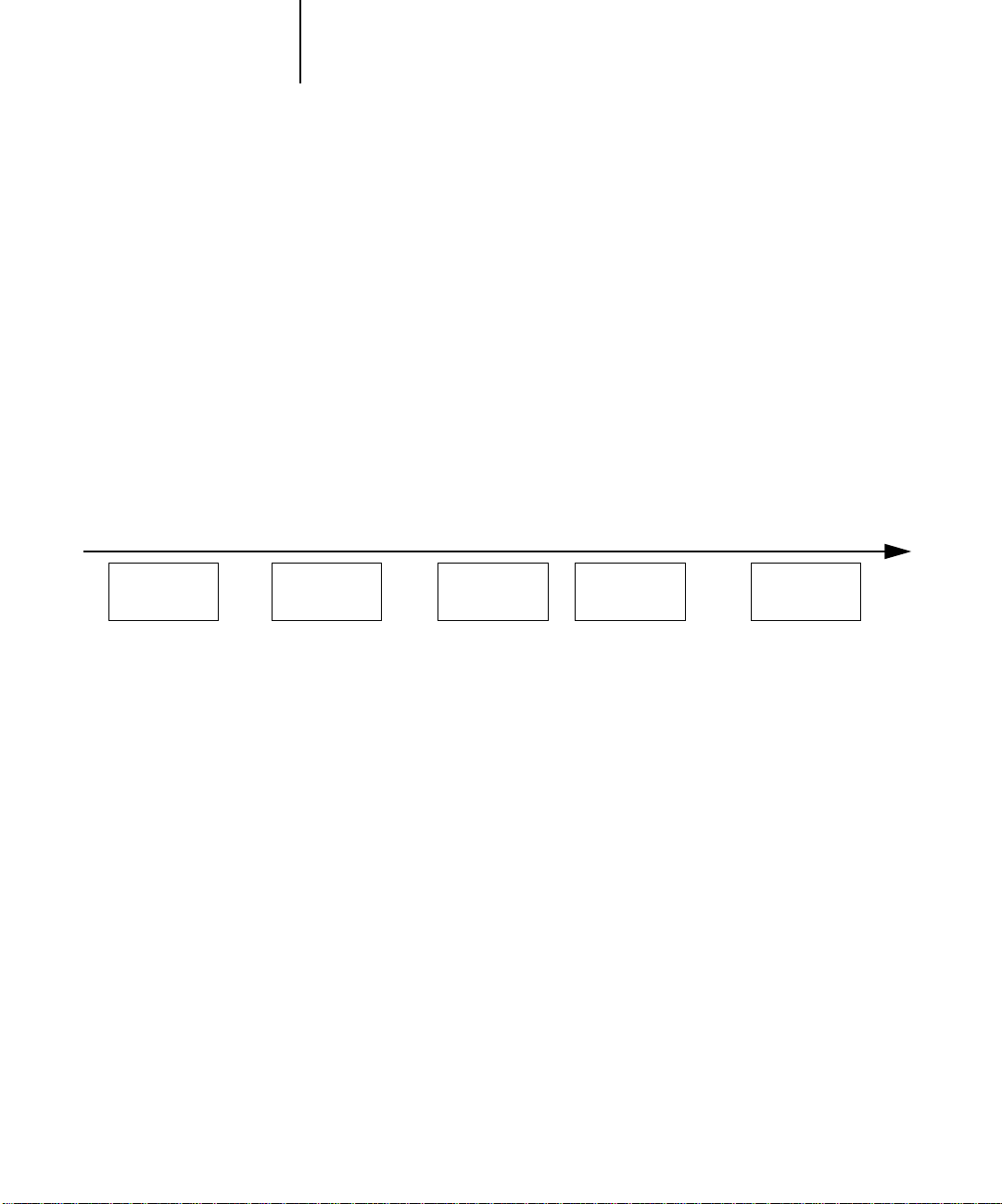
Consider that colors can be defined or modified at any stage in the workflow, as illustrated
in the following diagram.
Colors you define in an application Colors in output from the copie
Application
CMS
File format Printer driver
ColorWise
CMS
ColorWise
calibration
Page 19

2-5 Simple workflows
2
Select your colors wisely
For the colors you see on your monitor to match those on your printed output, they
must go through color management, including precise calibration of your monitor and
copier. If you are not equipped or inclined to maintain accurate monitor color
management, you may opt for an easier approach. First, determine which is more
important for you—printed colors or monitor displayed colors.
If displayed colors are more important, trust your eyes and your monitor. Visually
select colors on your monitor, but be aware that colors will be optimized only for your
monitor. When the document is opened on other monitors, the colors may look
different. And even though printed colors may not match those displayed on your
monitor, they will still print on the Fiery with good results.
If printed colors are your priority, choose colors from printed samples. Printed colors
will be consistent, even on different monitors. Print the palette of available colors from
business applications and then select colors from the printed samples. The Fiery comes
with color reference files on the user software CD (see page 5-2). You can also print the
color charts from the Control Panel and select colors by numbers or by name from the
printed samples. Advanced applications let you define colors in the easier-to-control
PANTONE and CMYK color spaces. See Chapter 5 for more advice on color
selection.
No matter which workflow most closely matches your own, you should calibrate your
copier regularly (see Chapter 3).
Page 20

2-6 Simple and Advanced Workflows
r
2
Select a short workflow
Every time colors are converted, performance and color accuracy are affected.
Therefore, a workflow with fewer steps minimizes the risk of error.
Workflow 1 using ColorWise calibration—minimal workflow
A minimal color workflow requires that you calibrate the copier. Set the CMYK
Simulation option to None, since simulation is not needed when colors are already
defined using CMYK values optimized for your calibrated copier.
CMYK Simulation set to None is useful when you want to prepare an output profile of
your calibrated copier or when you use less efficient color management from the
desktop (such as ColorSync or ICM).
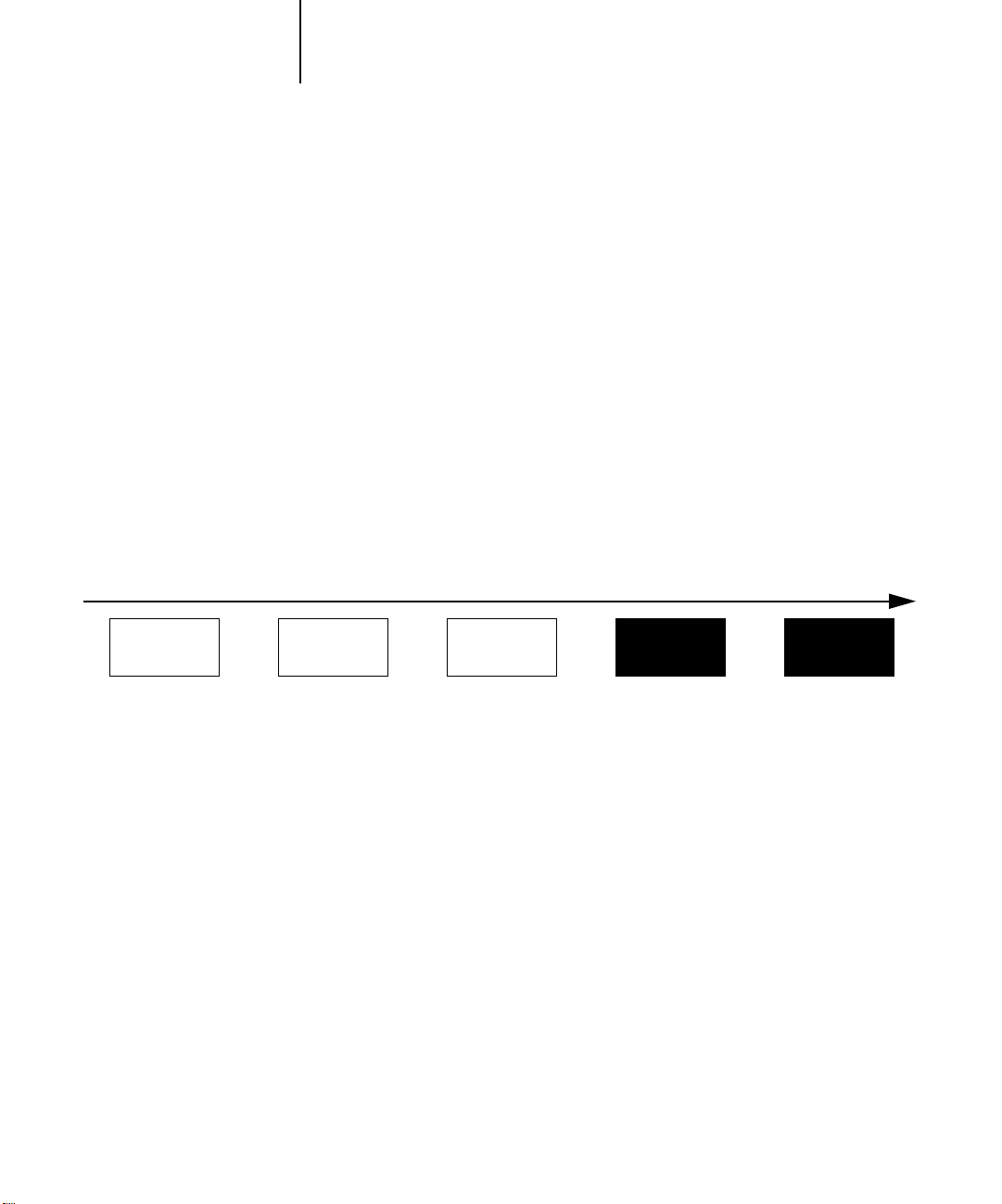
In this workflow, colors are modified only at the calibration stage. This is indicated by
the black box in the diagram below.
Workflow 1
Colors you define in an application Colors in output from the copie
Application
CMS
File format Printer driver
While this workflow lends some control over the color quality produced by the copier,
you should consider additional ColorWise color management, as described in the next
section.
ColorWise
CMS
ColorWise
calibration
Page 21
2-7 Simple workflows
r
2
Workflow 2 using ColorWise color management—standard workflow
Fiery servers are highly optimized for the specific copier they drive, and ColorWise
addresses many issues unique to your copier, including screens, individual toner
response, interactions among toners, natural smoothness of blends, and the capability
to render PANTONE and custom colors. The Fiery distinguishes text and graphic
from image elements, so the black channel information is preserved while parameters
used for CMYK color separations are maintained.
Conventional color management systems typically address only color conversions, and
they occupy your computer’s processor. When you use ColorWise, jobs leave your
computer faster to be processed more quickly on the Fiery.
The recommended standard color workflow (indicated by the black boxes in the
diagram below) uses ColorWise calibration and color management.
Workflow 2
Colors you define in an application Colors in output from the copie
Application
CMS
File format Printer driver
The Fiery comes into play near the end of the color workflow. To ensure that the colors
you have selected reach the Fiery and ColorWise in a usable form, you should bypass
any color management from applications and printer drivers. (Keep in mind, however,
that color management from applications and printer drivers is fully supported by
ColorWise (see “Advanced workflows” on page 2-10).
ColorWise
CMS
ColorWise
calibration
Page 22

2-8 Simple and Advanced Workflows
r
2
You must print with the CMYK Simulation print option set to match the CMYK
color space in your application when you selected the colors. Any CMYK Simulation
setting (except Match Copy) applies calibration, so the copier’s response will appear to
be stable.
The recommended values for CMYK Simulation are SWOP in America, Euroscale in
Europe, and DIC in Japan—choices that respect the color standard for each region. If
colors have been selected specifically for your calibrated copier, set CMYK Simulation
to None.
See the table on page 1-3 for the list and descriptions of ColorWise print options
affecting CMYK, RGB, PANTONE, and other colors.
Workflow 3 bypassing ColorWise—not recommended
Bypassing ColorWise color management, while an option, is not a recommended
workflow. When you bypass ColorWise, you must choose colors using only CMYK
formulas designed specifically for your copier, and you must print with the CMYK
Simulation option set to Match Copy. The Fiery still prints pages using your PostScript
files, and drives the copier and its accessories, but it does not perform CMYK color
transformation, nor does it consider the copier’s calibration. Calibration is needed in
order to get consistent output, since the color response from your copier’s engine varies
significantly depending on wear, heat, humidity, and service.
The diagram below indicates that no modifications are made to colors in this
workflow.
Workflow 3
Colors you define in an application Colors in output from the copie
Application
CMS
File format Printer driver
ColorWise
CMS
ColorWise
calibration
Page 23

2-9 Simple workflows
2
Turn off color management in your application
Generally, when printing to the Fiery, it is best to disable color management in the
application to ensure that the Fiery receives color data properly and prints it accurately.
Examples later in this chapter illustrate the advantage of disabling color management
in the application, and you can find more specific information in Chapters 6
through 9.
Save your files using color-safe settings
There are several additional steps you can take to ensure color accuracy.
• When saving EPS files, do not include PostScript Color Management information.
This minimizes the risk conflicting data and multiple color conversions. PostScript
Color Management causes your CMYK and RGB colors to be interpreted by the
Fiery as though they were supplied in the Lab color space and, as a result, to be
processed by CRDs rather than your simulation settings.
• Include ICC color information in files. ColorWise will not conflict with this
information, and such data can be useful to identify the specific color space used by
your files.
• Do not include halftone and transfer functions.
• Turn off color management in the printer driver.
On Windows machines, if the printer driver offers Image Color Matching options,
select Printer Image Color Matching.
On Mac OS computers, you should set the printer driver to include no color
management commands at print time (see page 1-18).
Page 24

2-10 Simple and Advanced Workflows
2
Advanced workflows
The following sections present advanced color management workflow examples for
three short-run printing and three color proofing situations. Each workflow example
consists of a brief description, steps for creating and manipulating the files, a list of the
ColorWise settings used in the example, and a table that summarizes the workflow.
NOTE: These examples use specific software packages to represent image-editing,
illustration, page-layout, and business/office applications; they are Adobe Photoshop,
Adobe Illustrator, QuarkXPress, and Microsoft PowerPoint, respectively.
Short-run printing examples
The following examples illustrate short-run printing on the Fiery.
Photoshop RGB workflow
This short-run workflow of printing an RGB image from Photoshop is one of the
simplest Fiery color workflows. In it, RGB data is sent from the application, through
the printer driver, to the Fiery, and the RGB-to-CMYK conversion takes place on the
Fiery using a CRD rather than in the application. Use the settings illustrated in this
workflow for printing photographs and artwork.
This document could be created as follows:
• Create an RGB image in Photoshop.
• Print the file directly to the Fiery.
See Chapter 7 for recommended print settings from Photoshop.
• Use ColorWise to convert the RGB image to copier CMYK for short-run printing.
The ColorWise settings used in this example are:
• RGB Source Profile set to EFIRGB or another RGB source definition
• Rendering Style set to Photographic
• RGB Separation set to Output
Page 25

2-11 Advanced workflows
2
The diagram below indicates the steps for this particular workflow in black.
Photoshop RGB workflow
Photoshop Printer driver
Read Embedded Profiles
Define RGB Source
Embed Source Profiles
Convert RGB to CMYK
Convert CMYK to CMYK
Select RGB Mode
Select CMYK Mode
Select Destination Profile
Save as TIFF
Save as EPS
Save as JPEG
Print
ColorSync Color Matching
PostScript Color Matching
(Mac OS-only)
Black and White
Color/Grayscale
Select Rendering Style (CRD)
Select RGB Separation: Output
Select RGB Separation: Simulation
Convert Press CMYK to Press Sim.
Convert Press CMYK to Custom Sim.
Select Copier CMYK Simulation: None
Turn Spot Color Matching On
Turn Spot Color Matching Off
Select Custom Output Profile
ColorWise
print options
Define RGB Source
Select RGB Source: None
Select Output Profile
Photoshop RGB with Illustrator and QuarkXPress CMYK and PANTONE colors
This workflow involves short-run printing of a complex page layout with images saved
in Photoshop, illustrations created in Illustrator, and PANTONE spot colors. A
Photoshop image is saved in an RGB color space using the EPS file format. Illustrator
artwork contains objects defined as CMYK and as PANTONE spot colors, and they
are saved using the Illustrator EPS file format. After all of these individual objects are
imported into QuarkXPress, additional design elements in QuarkXPress are colored
using CMYK process colors or PANTONE spot colors. Use the settings illustrated in
this workflow for printing brochures, newsletters, and other layouts.
This document could be created as follows:
• Create an RGB image in Photoshop and save it as an EPS.
• Create a graphic in Illustrator using CMYK and PANTONE colors and save as
Illustrator EPS.
• Use CMYK colors and a PANTONE color in a QuarkXPress document.
• Import the Illustrator EPS into QuarkXPress and place the Photoshop EPS image.
• Print the QuarkXPress document to the Fiery.
Page 26
2-12 Simple and Advanced Workflows
P
2
• Use ColorWise to convert the RGB image to copier CMYK, to adjust the process
colors for short-run printing, and to match the PANTONE spot colors using the
full copier gamut.
The ColorWise settings used in this example are:
• RGB Source Profile set to EFIRGB or another RGB source definition
• Rendering Style set to Photographic
• RGB Separation set to Output
• Spot Color Matching set to On
The diagram below indicates the steps for this particular workflow in black.
hotoshop RGB workflow with Illustrator, QuarkXPress CMYK, and PANTONE colors
Photoshop Illustrator QuarkXPress Printer driver
Read Embedded Profiles
Define RGB Source
Embed Source Profiles
Convert RGB to CMYK
Convert CMYK to CMYK
Select RGB Mode
Select CMYK Mode
Select Destination Profile
Save as TIFF
Save as EPS
Save as JPEG
Print
Read Embedded Profile
Define RGB Colors
Define CMYK Colors
Define PANTONE Colors
Convert RGB to CMYK
Convert PANTONE to CMYK
Embed Source Profile
Select Destination Profile
Export as TIFF
Save as EPS
Print
Read Embedded Profile
Define RGB Colors
Define CMYK Colors
Define PANTONE Colors
Convert RGB to CMYK
Convert CMYK to CMYK
Convert PANTONE to CMYK
Embed Source Profile
Select Destination Profile
Export as TIFF
Save as EPS
Print
(Mac OS-only)
Black and White
Color/Grayscale
ColorSync Color
Matching
PostScript Color
Matching
Select Rendering Style (CRD)
Select RGB Separation: Output
Select RGB Separation: Simulation
Convert Press CMYK to Press Sim.
Convert Press CMYK to Custom Sim.
Select Copier CMYK Simulation: None
Turn Spot Color Matching On
Turn Spot Color Matching Off
Select Custom Output Profile
ColorWise
print options
Define RGB Source
Select RGB Source: None
Select Output Profile
Page 27

2-13 Advanced workflows
2
Photoshop RGB with Illustrator CMYK and PANTONE and PowerPoint RGB
This workflow involves short-run printing of a complex presentation document with
images saved in Photoshop, illustrations created in Illustrator, and PANTONE spot
colors. All elements are imported into PowerPoint for output.
This document could be created as follows:
• Create an RGB image in Photoshop and save it as Photoshop EPS.
• Create a graphic in Illustrator using CMYK colors and a PANTONE spot color and
save as Illustrator EPS.
• Create a presentation in PowerPoint using RGB colors.
• Import the Illustrator EPS graphic into the PowerPoint presentation and place the
Photoshop EPS image.
• Print the PowerPoint document to the Fiery.
• Use ColorWise to convert the PowerPoint RGB colors and Photoshop RGB image
to copier CMYK, to adjust the process colors for more saturated short-run printing,
and to match the PANTONE spot colors using the full copier gamut.
The ColorWise settings used in this example are:
• RGB Source Profile set to EFIRGB or another RGB source definition
• Rendering Style set to Presentation
• RGB Separation set to Output
• Spot Color Matching set to On
Page 28

2-14 Simple and Advanced Workflows
P
2
The diagram below indicates the steps for this particular workflow in black.
hotoshop RGB and Illustrator CMYK and PANTONE in PowerPoint RGB workflow
Photoshop Illustrator PowerPoint Printer driver
Read Embedded Profiles
Define RGB Source
Embed Source Profiles
Convert RGB to CMYK
Convert CMYK to CMYK
Select RGB Mode
Select CMYK Mode
Select Destination Profile
Save as TIFF
Save as EPS
Save as JPEG
Print
Read Embedded Profile
Define RGB Colors
Define CMYK Colors
Define PANTONE colors
Convert RGB to CMYK
Convert PANTONE to CMYK
Embed Source Profile
Select Destination Profile
Export as TIFF
Save as EPS
Print
Define RGB Colors
Convert CMYK to RGB
Print
(Mac OS-only)
Black and White
Color/Grayscale
ColorSync Color
Matching
PostScript Color
Matching
Select Rendering Style (CRD)
Select RGB Separation: Output
Select RGB Separation: Simulation
Convert Press CMYK to Press Sim.
Convert Press CMYK to Custom Sim.
Select Copier CMYK Simulation: None
Turn Spot Color Matching On
Turn Spot Color Matching Off
Select Custom Output Profile
ColorWise
print options
Define RGB Source
Select RGB Source: None
Select Output Profile
Color proofing examples
The following examples illustrate methods for simulating the output from another
printing system, such as an offset press. Each of the proofing examples uses an ICC
profile to describe the destination color space. While some examples use built-in
simulation profiles, others use ColorWise Pro Tools (see Chapter 4) to download
custom ICC output profiles to the Fiery for use as simulation profiles.
Photoshop 5.x RGB-to-CMYK conversion using a custom ICC profile
This workflow is useful for prepress environments that have integrated ICC color
management and have profiles for the presses they use. In this example, an image in
Photoshop 5.x is converted from RGB to CMYK using Photoshop’s ICC color
conversion features in the CMYK Setup option. (For more information on CMYK
Setup, see your Photoshop 5.x documentation.) Using the Simulation settings available
in ColorWise, the CMYK image is printed to the Fiery, and the output is made to
appear as if it were printed on an offset press.
Page 29

2-15 Advanced workflows
2
This document could be created as follows:
• In Photoshop 5.x, set CMYK Model in CMYK Setup to ICC.
• In the Profile menu, select an ICC profile for the desired offset press. Click OK.
• Open an RGB image. From the Image pull-down menu select Mode>CMYK Color.
• Save the image as Photoshop EPS.
• Print directly to the Fiery.
• Use ColorWise Pro Tools to select a simulation profile or download a custom ICC
profile to the Fiery for use as a CMYK Simulation Profile.
The ColorWise settings used in this example are:
• CMYK Simulation Profile set to the desired press standard or to the corresponding
custom simulation (Simulation 1-10) if you downloaded your profile with
ColorWise Pro Tools
• CMYK Simulation Method set to Full
The diagram below indicates the steps for this particular workflow in black.
Photoshop RGB-to-CMYK workflow using ICC profile
Photoshop 5.x Printer driver
Read Embedded Profiles
Define RGB Source
Embed Source Profiles
Convert RGB to CMYK
Convert CMYK to CMYK
Select RGB Mode
Select CMYK Mode
Select Destination Profile
Save as TIFF
Save as EPS
Save as JPEG
Print
(Mac OS-only)
Black and White
Color/Grayscale
ColorSync Color Matching
PostScript Color Matching
Select Rendering Style (CRD)
Select RGB Separation: Output
Select RGB Separation: Simulation
Convert Press CMYK to Press Sim.
Convert Press CMYK to Custom Sim.
Select Copier CMYK Simulation: None
Turn Spot Color Matching On
Turn Spot Color Matching Off
Select Custom Output Profile
ColorWise
print options
Define RGB Source
Select RGB Source: None
Select Output Profile
Page 30

2-16 Simple and Advanced Workflows
2
Photoshop 5.x Built-in RGB-to-CMYK workflow
This workflow is useful for prepress environments that have not integrated ICC color
management and do not have profiles for the presses they use. In this example, an
image is converted from RGB to CMYK using Photoshop 5.x’s Built-in color
conversion features in the CMYK Setup option. (For more information on CMYK
Setup, see your Photoshop 5.x documentation). Using the Simulation settings available
in ColorWise, the CMYK image is printed to the Fiery, and the output is made to
appear as if it were printed on an offset press.
This document could be created as follows:
• Select the Built-in radio button from CMYK Setup in Photoshop 5.x’s
Color Settings.
• Adjust the Ink Options and Separation Options to match your offset press.
• Select the Tables radio button in CMYK Setup and click Save.
This saves your settings as a CMYK ICC profile that you will later download to the
Fiery as a custom simulation profile.
• Click on the Built-in radio button in CMYK Setup again and click OK.
• Launch ColorWise Pro Tools and download your new CMYK ICC profile to the
Fiery as a custom Simulation profile.
For the Appear in Driver as option in Profile Settings, select Simulation-1. (For more
information on downloading profiles, see page 4-4.)
• Open an RGB image in Photoshop 5.x. From the Image menu, select
Mode >CMYK Color. Save the image as Photoshop EPS.
• Print the image directly to the Fiery and choose Simulation-1 as the CMYK
Simulation Profile setting.
The ColorWise settings used in this example are:
• CMYK Simulation Profile set to Simulation-1
• CMYK Simulation Method set to Full
Page 31

2-17 Advanced workflows
2
The diagram below indicates the steps for this particular workflow in black.
Photoshop5.x RGB-to-CMYK workflow
Photoshop 5.x Printer driver
Read Embedded Profiles
Define RGB Source
Embed Source Profiles
Convert RGB to CMYK
Convert CMYK to CMYK
Select RGB Mode
Select CMYK Mode
Select Destination Profile
Save as TIFF
Save as EPS
Save as JPEG
Print
(Mac OS-only)
Black and White
Color/Grayscale
ColorSync Color Matching
PostScript Color Matching
Select Rendering Style (CRD)
Select RGB Separation: Output
Select RGB Separation: Simulation
Convert Press CMYK to Press Sim.
Convert Press CMYK to Custom Sim.
Select Copier CMYK Simulation: None
Turn Spot Color Matching On
Turn Spot Color Matching Off
Select Custom Output Profile
ColorWise
print options
Define RGB Source
Select RGB Source: None
Select Output Profile
Photoshop RGB and QuarkXPress CMYK
This workflow exemplifies the use of the RGB Separation feature of ColorWise. An
RGB image, originally saved in Photoshop, is printed to the Fiery from QuarkXPress.
To simulate how the RGB image would print on an offset press, the RGB Separation
feature of ColorWise is set to Simulation. This workflow—useful for proofing
brochures, newsletters, and other layouts—lets you maintain consistency by using the
source RGB file for multiple purposes.
This document could be created as follows:
• Create an RGB image in Photoshop and save it as Photoshop EPS.
• Place the EPS image in a QuarkXPress document.
• Create several process-colored page elements alongside the image and print.
• Use ColorWise to convert the RGB image to simulated press CMYK and to adjust
the process colors for proofing to the copier.
Page 32

2-18 Simple and Advanced Workflows
2
The ColorWise settings used in this example are:
• RGB Source Profile set to EFIRGB or another RGB source definition
• Rendering Style set to Photographic
• RGB Separation set to Simulation
• CMYK Simulation Profile set to SWOP
• CMYK Simulation Method set to Full
The diagram below indicates the steps for this particular workflow in black.
Photoshop RGB and QuarkXPress CMYK workflow
Photoshop QuarkXPress Printer driver
Read Embedded Profiles
Define RGB Source
Embed Source Profiles
Convert RGB to CMYK
Convert CMYK to CMYK
Select RGB Mode
Select CMYK Mode
Select Destination Profile
Save as TIFF
Save as EPS
Save as JPEG
Print
Read Embedded Profile
Define RGB Colors
Define CMYK Colors
Define PANTONE Colors
Convert RGB to CMYK
Convert CMYK to CMYK
Convert PANTONE to CMYK
Embed Source Profile
Select Destination Profile
Export as TIFF
Save as EPS
Print
ColorSync Color Matching
PostScript Color Matching
(Mac OS-only)
Black and White
Color/Grayscale
ColorWise
print options
Define RGB Source
Select RGB Source: None
Select Rendering Style (CRD)
Select RGB Separation: Output
Select RGB Separation: Simulation
Convert Press CMYK to Press Sim.
Convert Press CMYK to Custom Sim.
Select Copier CMYK Simulation: None
Turn Spot Color Matching On
Turn Spot Color Matching Off
Select Output Profile
Select Custom Output Profile
Page 33

P
P
rroodduucctt&
&
Fiery XJ
T
T
eecchhnnoollooggy
y
Page 34

Page 35

6
6-1 Understanding calibration
Chapter 6:
Color
Calibration
Calibrating your Fiery XJ M ensures consistent, reliable color output. You can calibrate
the Fiery XJ M in several ways:
™
• Scan a page from the copier glass and use automatic calibration (AutoCal
• Connect a densitometer to your Fiery XJ M and calibrate it from the Control Panel.
• Connect a densitometer to your Macintosh or IBM PC-compatible and download
calibration to your Fiery XJ M with the Fiery XJ Print Calibrator utility.
This chapter describes the function of calibration and describes how to calibrate your
Fiery XJ M.
NOTE: Changing calibration affects all jobs for all users, so you may want to limit the
number of people authorized to calibrate the Fiery XJ M and use Fiery XJ Print
Calibrator.
).
Understanding calibration
Calibration allows you to:
• Maximize the color reproduction capabilities of the Fiery XJ
• Ensure consistent color quality across time
• Produce consistent output across Fiery XJ servers of the same kind
• Optimize your Fiery XJ for use with EFICOLOR color management software
• Use your Fiery XJ as a proofing system
• Achieve better color matches when you’re reproducing spot colors, such as
PANTONE colors or other named color systems
• Linearize your Fiery XJ while maintaining the currently available density range
• Create custom calibration targets and custom calibration curves
Page 36

6
6-2 Color Calibration
How calibration works
Success in obtaining satisfactory print quality from a digital color printer depends on
many factors. Among the most important are establishing and maintaining optimal
toner densities. Density is a measure of the light absorbed by a surface. The saturation
of toner colors, which affects output densities from your copier, is affected by such
variables as room humidity and service settings, and also tends to drift over time.
Regular calibration corrects for day-to-day variations in densities.
Calibration works by creating calibration curves on your Fiery XJ server that
compensate for deviations from desired density values. These calibration curves are
generated by creating a measurements file—a file containing numerical values
corresponding to the amount of toner being printed for the full range of colors—and
comparing it to a target.
Measurements
Measurements files provide numerical values that correspond to your copier’s toner
density for each color. To create a measurements file, you can scan a page from your
copier and use AutoCal, connect an X-Rite DTP32 densitometer to the Fiery XJ M
and record values, or connect an X-Rite DTP32 densitometer to your Macintosh
computer’s modem port or your IBM-PC compatible’s serial port and measure values
with the Fiery XJ Print Calibrator utility. You may also be able to connect any Status T
densitometer to your Macintosh or IBM-PC if you have utility software provided by
the densitometer manufacturer to create a measurements file.
Targets
Target files define desired calibration results. Several target files are provided with the
Fiery XJ M, and you can create additional ones as needed by modifying existing
targets. When you calibrate the Fiery XJ M, you can select the target file that
corresponds to the type of printing you are doing.
The targets provided with the Fiery XJ M are:
• Copier-M—Optimized for best results for specific copier performance. You should
use the copier target if you are going to use the copier’s EFICOLOR profile to print
CMYK data or the Color Rendering Dictionaries (CRD). The CRDs are used if you
Page 37

6
6-3 Understanding calibration
print an RGB file from Photoshop, or if you use a PostScript Level 2 Printer Driver
(Adobe PostScript Printer Driver for Macintosh, Adobe PostScript Printer Driver for
Windows, or Apple LaserWriter Printer Driver version 8.0 or later).
• DIC—Japanese press standard.
• Euroscale—European press standard.
• Linear—Results in output that divides the maximum measured density for each
color into equal density steps to provide an even distribution of tones over the
copier’s density range. When you linearize the Fiery XJ M, the entire measured
density range in each color channel is divided into equal steps. Equal steps in ink
percentage, such as 0%, 10%, and 20%, are printed in equal steps in density, and l
appear as roughly equal visual steps. This gives a linear response using the range of
densities available.
• SWOP-Coated—US press standard.
Scheduling calibration
In general, you should calibrate the Fiery XJ M at least once a week. If it is very
important to maintain consistent colors, or if your Fiery XJ M is subject to wide
fluctuations in temperature or humidity, you should calibrate every few hours. In
general, to get the best performance from your copier, calibrate whenever there is a
noticeable change in print quality.
If you need to split a print job into two or more batches, it is especially important to
calibrate before printing each batch.
You should also calibrate your Fiery XJ M system after copier maintenance. However,
because your copier may be unstable immediately after maintenance, you should wait
until you have printed approximately 50 pages before you calibrate.
NOTE: Copier output is very sensitive to changes in temperature and humidity. To
minimize these effects, your copier should not be installed near a window or in direct
sunlight, or near a heater or air conditioner.
Your copier may have a self-calibration feature that optimizes toner densities after
scanning a test page on the copier glass or some other method. You can use this feature
in conjunction with Fiery XJ M calibration. Always run the copier’s self-calibration
Page 38

6
6-4 Color Calibration
routine before calibrating. Using the copier’s calibration feature alone will not
necessarily bring output densities from your copier to the optimal values for
Fiery XJ M printing.
NOTE: All color copiers allow you to adjust printed color from their control panels. You
can typically increase or decrease toner density for one or all toner colors. These
control panel settings affect copies made from the copier glass, and may affect
Fiery XJ M output as well. If they do, make sure these settings remain the same
(preferably at a neutral position) prior to calibration, and from one print job to the
next. If you change these settings, calibrate the Fiery XJ M when you are finished
changing settings.
Set up a standard printing environment in Control Panel Setup by selecting printing
options that correspond to the way you usually print. Then print one or more standard
color pages. You can print the Color Charts from the Control Panel and the Color
Reference pages that are included with your user software. See “Using the Color
Reference pages” on page 2-4 or page 3-13. All of these pages include fully saturated
color patches and pale tints of cyan, magenta, yellow, and black. Images with skin
tones offer a very good basis for comparison. You can save and compare pages you
printed at different times. If there is a noticeable change in appearance, you should
calibrate or linearize your Fiery XJ M system.
If your solid density patches (100% cyan, magenta, yellow or black) look less saturated
with time, show the pages to the copier or printer technician to find out if an
adjustment can be made to improve the output.
Checking calibration status
Before printing a job, you should check to see whether the Fiery XJ M is calibrated,
what target was used, and when the printer was last calibrated. You can view
information about the last calibration:
• At the Fiery XJ M, by printing a Configuration Page or Test Page from the Control
Panel Functions menu.
• With the Fiery XJ Print Calibrator utility by choosing Calibration Status from the
Server menu. This method gives you additional information. See “To view
information with the Fiery XJ Print Calibrator:” on page 6-14.
Page 39

6
6-5 Understanding calibration
Using a densitometer
If you calibrate your Fiery XJ M from either the Control Panel or the Fiery XJ Print
TO CONNECT THE X-RITE DTP32:
Calibrator utility, you can use a densitometer to input color information. The
procedure is the same in both cases.
For additional information about setting up and using your densitometer, see the
documentation that came with it.
Setting up the densitometer
Before you calibrate the Fiery XJ M, configure and zero your reflection densitometer to
prepare for measuring the printed patches.
1. Plug the square end of the interface cable (like a modular phone plug) into the I/O
port on the side of the X-Rite DTP32.
Square connector
Page 40

6
6-6 Color Calibration
2. Attach the round 8-pin mini-connector to the modem port on the back of your
Macintosh. Or attach the 9-pin connector to the COM1 or COM2 port on your PC. Or
attach the 9-pin connector to the serial port on the back of the Fiery XJ M
Macintosh PCServer
3. If you are using a Macintosh, attach the round 4-pin mini-connector to one of the
Apple Desktop Bus (ADB) ports.
The Macintosh ADB port provides power to the DTP32.
Page 41

6
Small connector
AC adapter
6-7 Understanding calibration
4. If you are using a PC, a Macintosh without an ADB port available (or a PowerBook), or
the Fiery XJ M, use the optional AC adapter (available from X-Rite) to provide power.
If you use the optional AC adapter, plug the small connector on the adapter cable into
the side of the X-Rite DTP32 and plug the adapter into a wall outlet.
TO CONNECT THE X-RITE DTP32 TO A POWERBOOK:
1. Turn the PowerBook off.
2. Connect the network cable to the PowerBook’s EtherTalk port.
3. Plug the square end of the densitometer interface cable into the I/O port on the side
of the X-Rite DTP32.
4. Attach the round 8-pin mini-connector to the serial port on the PowerBook.
5. If the densitometer display indicates that densitometer battery power is low, use the
external AC adapter for the densitometer.
N
OTE: Don’t connect the densitometer to the PowerBook ADB port.
6. Configure the densitometer to factory defaults and save the settings. (See the
densitometer manual for details.)
Factory default settings for the X-Rite DTP32 are:
Page 1 LANG (ENG) TONE (loud) TYPE (ser)
Page 2 BAUD (9600) HAND (xon) AXMT (on)
Page 3 DPT (on) SEP (spc) DLIM (crlf)
Page 4 DEF (off) X10 (off ) DAP (off )
Page 42

6
6-8 Color Calibration
Page 5 M/M (max) LOCK (off)
TO CALIBRATE THE X-RITE DTP32:
7. Turn on the PowerBook.
8. In the PowerBook Setup Control Panel, select Normal for Modem Controls.
9. Calibrate the densitometer, as described below.
1. On the X-Rite DTP32, simultaneously press the two buttons marked MENU.
The words MAIN MENU appear in the display.
2. Press the p1 key until p2 appears.
3. Press the cal key.
CALIBRATION appears in the display.
4. Press the den key.
CALIBRATING TRANSMISSION is displayed, followed by the words INSERT CAL STRIP.
5. Position the strip guide at 5.
Strip guide
6. Insert the arrow end of the Auto-Cal strip into the entrance of the X-Rite DTP32 until
the roller starts pulling the strip.
READING appears momentarily, followed by the density values and CALIBRATION OK.
UNRECOGNIZABLE STRIP appears, try cleaning the strip (see your X-Rite DTP32
If
Operating Manual).
7. Recalibrate the densitometer at least once month.
Page 43

6
6-9 Understanding calibration
Measuring values with a DTP32 densitometer
You can connect a DTP32 densitometer to the Fiery XJ M or to your Macintosh or
TO MEASURE CALIBRATION PATCHES WITH AN X-RITE DTP32:
PC if you are using Fiery XJ Print Calibrator. The densitometer scans the density of
the first patch, automatically advances to the next patch, and automatically transmits
the measured values to the Fiery XJ M or Fiery XJ Print Calibrator. The DTP
densitometer has an adjustable strip guide to the right of the strip entrance.
After each column is scanned, the density measurements are used to create a
Measurements file. In general, valid measurements for all patches fall within the range
of -0.05 to 3.05.
1. When prompted on the Control Panel or Fiery XJ Print Calibrator, position the pointer
on the strip guide to 15 and click OK on the Control Panel or Fiery XJ Print Calibrator
to begin measuring.
First, you’ll measure the cyan column. Slide the paper guide left or right until the
arrow points to 15.
2. With the arrow below the cyan column pointing towards the densitometer, align the
right side of the patches page with the strip guide.
Page 44

6
6-10 Color Calibration
3. Insert the patches page into the densitometer until it rests against the drive rollers
and the motor is activated.
4. Hold the page against the guide to prevent any skewing while the strip is being
5. When prompted, move the strip guide to 30 and measure the magenta column.
6. Turn the patches page around so that the arrow above the yellow column is pointing
7. When prompted, align the right side of the patches page with the strip guide and
8. When prompted, move the page guide to 15 and measure the black column.
There may be a slight hesitation before the rollers start.
measured.
After the strip is measured, Pass #1 of 4 OK! appears in the densitometer display.
Transmitting Data appears briefly after each pass.
After the magenta strip is measured, Pass #2 of 4 OK! appears in the densitometer
display.
toward the densitometer.
Leave the strip guide set to 30.
measure the yellow column.
After the yellow strip is measured, Pass #3 of 4 OK! appears in the densitometer
display.
After the black strip is measured, Pass #4 of 4 OK! appears in the densitometer display.
NOTE: If there is a problem measuring a color, follow the instructions on the
densitometer to remeasure it.
Page 45

6
6-11 Understanding calibration
Calibrating the Fiery XJ M from the Control Panel
USING AUTOMATIC CALIBRATION:
You can calibrate the Fiery XJ M from the Control Panel by connecting a densitometer
to the serial port on the back of the Fiery XJ M, or by using AutoCal.
Automatic calibration
You can calibrate the Fiery XJ M without a densitometer with AutoCal.
1. When the Fiery XJ M restarts, press the Menu key when prompted to enter Setup.
2. Press Run Setup.
3. Scroll down to choose Calibration.
4. Choose Calibrate.
The Calibration Method screen appears.
5. Select Copier Glass for the Calibration Method.
6. When prompted to Select Target, use the up/down arrow keys to scroll through the list
of target names, then choose OK.
You can choose from the list of all targets on the Fiery XJ M hard drive. This includes
several targets included with the Fiery XJ M as well as any custom targets you have
loaded.
7. When prompted, select Yes to print the Measurements page.
This page is comprised of bands of color that will be measured by the copier and then
compared to the target calibration.
After the page is printed, the Measure Page screen displays.
8. Select Yes and then choose OK.
Page 46

6
6-12 Color Calibration
9. When prompted “Position page on copier, then press OK,” place the Measurements
page on the copier glass and click OK.
TO CALIBRATE WITH A DENSITOMETER:
Position the page as you would a standard portrait copy with the top of the page at the
far edge of the copier glass. The copier scans the page on the glass, creates a
measurements table, and automatically compares it to the target you selected. It then
adjusts measurements to match the target.
10. When prompted to Print Comparison Page, select Yes.
Verify that the colors on the page are correct.
11. When Prompted to Overwrite Calibration, select Yes.
12. Select Yes to confirm.
13. When calibration is complete, choose Exit Calibration. This automatically restarts your
Fiery XJ M.
Calibrating with a densitometer
To calibrate with a densitometer, the Fiery XJ M must have a serial port to connect the
densitometer to. Contact your authorized service/support center for information about
Fiery XJ M hardware.
1. Connect the DTP32 densitometer to your Fiery XJ M
For instructions, see “Setting up the densitometer” on page 6-5.
2. Restart the Fiery XJ M and press the Menu key when prompted to enter Setup.
3. Press Run Setup.
4. Scroll down to choose Calibration.
5. Choose Calibrate.
The Calibration Method screen appears.
6. Select Densitometer for the Calibration Method.
7. When prompted to Select Target, use the up/down arrow keys to scroll through the list
of target names, then choose OK.
Page 47

6
6-13 Understanding calibration
8. When prompted, select Yes to print the Measurements page.
9. Select Yes and then choose OK.
10. When prompted on the Control Panel, position the cyan strip in the densitometer.
You can choose from the list of all targets on the Fiery XJ M. This includes several
targets included with the Fiery XJ M as well as any custom targets you have created
from your workstation with Fiery XJ Print Calibrator.
This page is comprised of swatches of color that will be measured by the densitometer
and then compared to the target calibration.
After the page is printed, the Measure Page screen displays.
See “Measuring values with a DTP32 densitometer” on page 6-9 for instructions.
Status messages display the progress of scanning and collecting measurements. If there
is a problem, you may need to calibrate your densitometer. See “To calibrate the X-Rite
DTP32:” on page 6-8.
11. When prompted, repeat step 10 to scan magenta, yellow, and black.
12. When prompted to Print Comparison Page, select Yes.
This page provides you with a preview of the selected calibration.
13. When Prompted to Overwrite Calibration, select Yes.
14. Select Yes to confirm.
Status messages display progress information.
15. When calibration is complete, choose Exit Calibration. This automatically restarts your
Fiery XJ M.
Removing calibration
If desired, you can remove calibration from the Fiery XJ M. In general, it is not
necessary because any new calibration replaces the existing one.
TO REMOVE CALIBRATION USING THE CONTROL PANEL:
1. When the Fiery XJ M restarts, press the Menu key when prompted to enter Setup.
2. Press Run Setup.
Page 48

6
6-14 Color Calibration
3. Scroll down to choose Calibration.
4. Choose Remove Calibration.
5. When prompted, verify that you want to proceed with removing calibration.
The current calibration curves are removed and the printer is uncalibrated. After
calibration is removed, you can download a new calibration.
Using the Fiery XJ Print Calibrator utility
The Fiery XJ Print Calibrator utility allows you to perform extended calibration
procedures from your networked workstation. You can calibrate to targets provided
with your Fiery XJ M, or you can customize targets and calibration curves to suit the
specific needs of your printing environment.
NOTE: The utilities for Macintosh and Windows users are fundamentally the same;
differences are noted in this chapter. Screens for both the Macintosh and Windows
utilities appear in this document.
TO VIEW INFORMATION WITH THE FIERY XJ PRINT CALIBRATOR:
1. Double-click the Fiery XJ Print Calibrator icon.
The Chooser window appears.
2. Select the Fiery XJ M in the Chooser window that appears and click Connect or OK.
If there is no Measurements file on the Fiery XJ M or no Target selected, you will be
notified during startup.
The Fiery XJ Print Calibrator main window and File, Edit, Measurements, Server, and
Window menus appear. Buttons for the main Fiery XJ Print Calibrator functions
appear in this window. The current status is displayed at the bottom of the window.
The functions unavailable at a particular time are dimmed and cannot be selected.
Page 49

6
6-15 Using the Fiery XJ Print Calibrator utility
The buttons are:
Measurements Displays density values in the current measurements
file.
Target Allows you to select a new target for calibration or for
customizing. Displays the currently selected target.
Edit Calibration Allows you to view the current measured and target
curves and customize the selected target.
Test Prints a page so that you can view the results of
calibration before changing the calibration on the
Fiery XJ M.
Apply Calibration Updates the calibration on the Fiery XJ M.
Page 50

6
6-16 Color Calibration
3. To view current calibration information, choose Calibration Status from the Server
menu.
The Server Calibration status dialog displays: the user name of the person who last
calibrated the Fiery XJ M, the name of the current Fiery XJ M, the date and time of
the current measurement file, the file name of the target used for the last calibration,
and the date and time of the most recent calibration.
4. To calibrate a different Fiery XJ M, choose Open Fiery XJ from the File menu.
Measurements
Measurements files provide toner values that correspond to colors. You can measure a
page of swatches with a densitometer and import the measurements.
Page 51

6
6-17 Using the Fiery XJ Print Calibrator utility
The creation date and time of the current measurements file appears below the
Measurements icon. If there is no measurements file, see “To create a measurements file
TO USE MEASUREMENTS:
to be imported:” on page 6-18.
1. Click the Measurements icon to view values in the current measurements file.
Page 52

6
6-18 Color Calibration
2. If you want to use a different measurements file, choose Import from the
Measurements menu; if you do not want to change the file, go to the Target section.
TO CREATE A MEASUREMENTS FILE TO BE IMPORTED:
3. When prompted, select the new measurements file to use and click OK.
1. Connect the DTP32 densitometer to your Macintosh or PC.
2. Choose Densitometer from the Measurements menu.
N
OTE: Creating a measurements file from a densitometer connected to your PC is not
supported with Windows 3.x.
3. Select the port connected to the densitometer in the Select Densitometer pop-up
menu.
Page 53

6
6-19 Using the Fiery XJ Print Calibrator utility
4. Click Start.
5. Follow the on-screen instructions to measure patches.
For instructions, see “Measuring values with a DTP32 densitometer” on page 6-9.
6. When you are finished, click Accept.
You can save the measurements file so that you can use it again by choosing Export
from the Measurements menu. This saves the values in the Measurements file that you
can use later without having to remeasure by importing it.
Working with targets
Target files are files containing desired calibration goals. Several target files are provided
with the Fiery XJ M, and you can create additional ones as needed. You can then select
the target file that corresponds to the type of printing you are doing.
The text under the Target button in the Fiery XJ Print Calibrator main window
displays the name and creation date and time for the currently selected target.
TO SELECT A TARGET:
1. Click the Target button in the Fiery XJ Print Calibrator window.
A dialog box displays a list of target files available on the Fiery XJ M.
Page 54

6
6-20 Color Calibration
2. If desired, click Local to select a target on your workstation, if not, go to step 3.
3. Select a target and click Open.
TO BACK UP TARGETS:
• Choose Backup Targets from the Server menu to copy the target files on the Fiery XJ M
to your workstation.
Files are saved in a folder called Backup in the Fiery XJ Print Calibrator folder. You can
save targets for safekeeping. You should always save targets before updating Fiery XJ M
system software to ensure that no custom targets are lost.
TO REMOVE TARGETS FROM THE FIERY XJ M’S HARD DISK:
1. Choose Remove Target from the Server menu.
2. Select the target(s) and click OK.
Page 55

6
6-21 Using the Fiery XJ Print Calibrator utility
You may want to do this to free up disk space (although these files are small) and to
make sure that no one uses the wrong target file. You should always use the Backup
Targets command to save targets before you delete them.
Editing calibration
You can edit the current calibration curve or the target file, and save the changes as a
new target calibration file. This allows you to fine tune the calibration on your
Fiery XJ M to meet your exact specifications.
The creation date and time of the current calibration appear under the Edit
Calibration button.
NOTE: The values in these screens do not represent standard values for calibration. They
are intentionally exaggerated for example purposes.
Page 56

6
6-22 Color Calibration
TO VIEW TARGET/MEASURED CURVES OR EDIT CALIBRATION:
1. Click the Edit Calibration button.
The Edit Calibration dialog box appears.
Page 57

6
6-23 Using the Fiery XJ Print Calibrator utility
You can use this dialog box to view measured or target curves or to edit calibration
curves. The graph on the left side of the window allows you to view and manipulate
color output values; the areas on the right allow you to adjust other values. The View
Channels and View Curves areas specify which curves display on the graph.
2. In the View Channels area, verify that the channels you want to edit are selected.
You can view the channels for all four color channels (Cyan, Magenta, Yellow, and
Black), or in any combination. This aids in fine tuning edits and when editing curves
on a monochrome screen.
NOTE: If all channels are turned on initially, they may overlap so you will have to move
or turn off the topmost channel to see other channels.
3. In the View Curves area, verify that the curves you want to edit are selected.
Choose Target/Measured to view the target or measured curve; choose Custom to view
and edit the calibration curves. If you selected Target/Measured, you can use the check
boxes to specify whether to view Target, Measured, or both curves.
Page 58

6
6-24 Color Calibration
TO VIEW THE MEASURED CURVE:
• Click Target/Measured and Measured in the View Curves area.
These curves represent the values in the measurements file and cannot be changed.
Page 59

6
6-25 Using the Fiery XJ Print Calibrator utility
NOTE: You can click Target to compare the target curve to the measured curve. The
closer the measured densities are to the target densities, the better the results you’ll get
from calibration.
TO EDIT THE TARGET CURVE:
1. Click Target/Measured and Target on the right side of the dialog box.
2. Adjust the values in the Maximum Density areas for each color to adjust the endpoints
of the target curve as needed.
You can enter a value from 0.1 to 3.0.
Page 60

6
6-26 Color Calibration
The rest of the curve adjusts to match the endpoint.
Page 61

6
6-27 Using the Fiery XJ Print Calibrator utility
TO EDIT CUSTOM CURVES:
1. Click Custom to edit the curve.
Page 62

6
6-28 Color Calibration
2. From the Apply setting to pop-up menu, choose the channels to be adjusted in the
Lightness/Darkness area of the window.
3. If needed, use the Brightness menu to adjust brightness.
Choose Lightest for a substantially lighter image, Darkest for a substantially darker
image, or one of the options in between.
NOTE: If you change a value for a color with the Brightness menu, it overrides values
set elsewhere in the dialog box.
4. If needed, adjust the Dot Gain value.
This is used for simulating press output and should be used with a press target. You can
choose either the North American or European standard. Then enter the desired Dot
Gain in the text box(es). The valid values for North American gain at 50% input are
0%-50% output. The valid values for European at 40% input are 0%-60% gain on
output; the valid values for European at 80% input are 0%-20% gain on output.
If you use Dot Gain values, the curve is smoothed so that there are no spikes or jumps
in output value.
NOTE: You will need to measure this value with a densitometer.
Page 63

6
6-29 Using the Fiery XJ Print Calibrator utility
5. If necessary, in the graph, click and drag points to adjust the curve.
The graph maps input percentage to output percentage in 10% increments. The curve
you selected appears, and points along the curve are marked so that you can adjust
them.
NOTE: You should adjust points in this way after you have entered values in the other
area of the window. If you attempt to change values after you have adjusted the curve
on the graph, values may not be valid.
Page 64

6
6-30 Color Calibration
6. When you are finished, click Save Target and enter a name for the new target.
This saves the target file to your Macintosh or PC hard disk so that you can use it again
or continue editing it later.
NOTE: If you edited one of the press standard targets, make sure that you include the
original standard name (SWOP, DIC, Linear, or Euroscale) in the new target name.
This ensures that the correct information appears on the Calibrator Test Page.
Testing and applying calibration
You can view a sample of calibration before you apply it to your Fiery XJ M. You can
print:
• Calibrator Test Page—This page is provided with Fiery XJ Print Calibrator and
shows a comparison of uncalibrated and calibrated data.
• User defined CALIB.EPS in Hold Queue— You can create an Encapsulated
PostScript (EPS) file in any application and name it CALIB.EPS. Then print the file
to the Hold Queue of the Fiery XJ M from your application or save it as an EPS file
and download it to the Hold Queue with the Fiery XJ Downloader.
Page 65

6
6-31 Using the Fiery XJ Print Calibrator utility
TO TEST AND APPLY CALIBRATION:
1. Click Test in the Fiery XJ Print Calibrator main window.
2. Specify which page to print and click Print.
3. When you have visually verified that the test page displays appropriate color values,
click Apply Calibration.
4. Click Continue when prompted to verify that you want to update calibration.
5. When you are finished, choose Quit (Macintosh) or Exit (Windows) from the File menu
to close the Fiery XJ Print Calibrator application.
Page 66

6
6-32 Color Calibration
Removing calibration
If desired, you can remove calibration from the Fiery XJ M. In general, it is not
TO REMOVE CALIBRATION WITH THE FIERY XJ PRINT CALIBRATOR:
necessary because any new calibration replaces the existing one.
1. Start the Fiery XJ Print Calibrator.
2. Choose Remove Calibration from the Server menu.
3. When prompted, verify that you want to proceed with removing calibration.
The current calibration curves are removed and the printer is uncalibrated.
Page 67

P
P
rroodduucctt&
&
Fiery X2
T
T
eecchhnnoollooggy
y
Page 68

8-1 Introduction to color calibration
8
Chapter 8:
Color Calibration
Calibrating the Fiery X2 ensures consistent, reliable color output. You can calibrate the
Fiery X2 in the following ways:
• Using AutoCal from the Fiery X2 Control Panel—AutoCal allows you to obtain
measurements from the copier and apply a calibration using the copier’s built-in
scanner.
• Using Fiery Print Calibrator and a densitometer from a remote computer—By
connecting an X-Rite DTP32 automatic scanning densitometer to the serial port on
your computer, you can quickly measure color patches and download measurements
to the Fiery X2 using Fiery Print Calibrator.
This chapter describes the purpose of calibration and provides instructions for all
calibration procedures. Calibrating with AutoCal from the Fiery X2 Control Panel is
described first; calibrating with Fiery Print Calibrator and a densitometer is described
on page 8-8.
For information on advanced calibration and simulation features available with Fiery
Print Calibrator, such as editing targets and creating custom targets, see Chapter 9.
The Fiery Print Calibrator procedures described in these chapters are fundamentally
the same for Windows and Mac OS computers. The main differences are the interface
cable and the port used to connect to the densitometer. The term “computer” is used
to refer to any computer running Fiery Print Calibrator.
Introduction to color calibration
A calibration is generated from two components that originate separately:
measurements and a target.
• Measurements represent the actual color behavior of the copier; they are computed
from readings taken by the copier’s scanner or a densitometer.
• Targets represent the goal of printing, such as obtaining pleasing color from the
copier or simulating another print device. A copier-specific target is provided with
the Fiery X2.
Page 69

8-2 Color Calibration
8
Calibration generates curves describing various color densities based on a specified
target and a set of measurements that you provide.
Once you have calibrated the Fiery X2 with Fiery Print Calibrator, a calibration is
stored on the Fiery X2; this calibration is referred to as the “resident calibration.” The
resident calibration is applied to all print jobs unless bypassing of calibration is
specified by setting the CMYK Simulation print option to Match Copy (see
Appendix A).
NOTE: Changing the resident calibration has the potential to affect all jobs for all users,
so you may want to limit the number of people authorized to perform calibration. An
Administrator password can be set to control access to calibration from the Fiery X2
Control Panel. Administrator and Operator passwords can be set with Fiery WebSetup
to control access to calibration with Fiery Print Calibrator.
Understanding calibration
The Fiery X2 allows you the flexibility to choose a standard calibration or a custom
calibration. A standard calibration uses one of the targets provided with the Fiery X2
(Copier-M or Linear) with a new set of measurements.
Calibration allows you to:
• Maximize the color reproduction capabilities of the Fiery X2
• Ensure consistent color quality across time
• Produce consistent output across Fiery X2 servers of the same engine
• Achieve better color matches when reproducing spot colors, such as PANTONE
colors or other named color systems
• Optimize the Fiery X2 for using ColorWise Color Rendering Dictionaries (CRDs)
and CMYK simulations, and for using ICC-compatible profiles when printing RGB
color data
• Linearize the Fiery X2 while maintaining the currently available density range
Chapter 9 discusses advanced calibration techniques, including how to:
• Use the Fiery X2 as a proofing system by printing press simulations
• Create custom calibration and simulation targets
Page 70

8-3 Understanding calibration
8
How calibration works
Success in obtaining satisfactory print quality from a digital color copier depends on
many factors. Among the most important are establishing and maintaining optimal
toner densities. Density is a measure of the light absorbed by a surface. By carefully
regulating toner densities, you can obtain consistent printed color.
Even with a calibrated system, toner density is affected by such variables as room
humidity and service settings; it also tends to drift over time. Regular measurement
detects day-to-day variations in densities, and calibration corrects for them.
Calibration works by creating calibration curves on the Fiery X2 that compensate for
the difference between actual and desired density values.
Calibration curves and target curves are the graphic equivalent of transfer functions,
which are mathematical descriptions of changes that will be made to the data you start
with. Transfer functions are often graphed as Input/Output curves.
Target curves (targets, for short) result from applying one or more transfer functions in
sequence. The server generates calibration curves after comparing measured values to
the final target values for each of the four toner colors.
Measurements
Measurements files contain numerical values that correspond to the toner density
produced by the copier when it prints solid cyan, magenta, yellow, and black, and
graduated tints of those colors.
To create a measurements file, you first print a page of color patches from the Control
Panel or from Fiery Print Calibrator to the copier. Then you measure the patches,
using either the copier’s scanner or an X-Rite DTP32 densitometer connected to a
computer on the network. The new measurements are automatically downloaded to
the Fiery X2.
You can print a calibration Comparison Page showing the result of using the new
measurements with any of the current targets. When you are satisfied with a particular
combination of measurements and target, you apply the calibration to the Fiery X2;
this becomes the new resident calibration.
Page 71

8-4 Color Calibration
8
NOTE: You might also be able to create measurements with a different brand Status T
densitometer if the densitometer manufacturer provides utility software to create a
measurements file.
Targets
Target files define desired calibration results. Two target files are provided with the
Fiery X2. You can create additional ones by modifying existing targets with Fiery Print
Calibrator. When you calibrate the Fiery X2, you can select the target file that
corresponds to the typical printing goals at your site. This becomes the resident
calibration target that is used by default.
The calibration targets provided with the Fiery X2 are:
• Copier-M—Optimized for best results with the copier.
Linear—Results in output that divides the maximum measured density for each
•
color into equal density steps to provide an even distribution of tones over the
copier’s density range. When you linearize the copier, the entire measured density
range in each color channel is divided into equal steps. Equal steps in toner
percentage, such as 0%, 10%, and 20%, are printed in equal steps in density, and
appear as roughly equal visual steps. This gives a linear response using the range of
densities available.
You can store targets on the computer where you use Fiery Print Calibrator, on another
connected disk, or on the Fiery X2 disk (or all three).
Scheduling calibration
In general, you should calibrate the Fiery X2 at least once a day, depending on the
volume of print jobs. If it is very important to maintain consistent colors, or if the
copier is subject to wide fluctuations in temperature or humidity, calibrate every few
hours. Calibrate when you change paper stock. In general, to get the best performance
from the copier, calibrate whenever there is a noticeable change in print quality.
If you need to split a print job into two or more batches, it is especially important to
calibrate before printing each batch.
Page 72

8-5 Understanding calibration
8
You should also calibrate the Fiery X2 system after copier maintenance. However,
because the copier may be less stable immediately after maintenance, wait until you
have printed approximately 50 pages before you calibrate.
NOTE: Output from the copier is very sensitive to changes in temperature and
humidity. To minimize these effects, the copier should not be installed near a window
or in direct sunlight, or near a heater or air conditioner. Paper is sensitive to climate
changes as well, and should be stored in a cool, stable environment.
The copier has a self-calibration feature that optimizes toner densities. If you never
calibrate the Fiery X2 from Fiery Print Calibrator or from the Control Panel, the selfcalibration feature can improve the color output of print jobs. Using the copier’s selfcalibration feature alone will not necessarily bring output densities from the copier to
the optimal values for Fiery X2 printing. However, if you regularly calibrate the
Fiery X2, your print jobs can sometimes be improved by asking a service technician to
disable the copier’s self-calibration feature.
The copier allows you to adjust printed color from its touch panel display. You can
typically increase or decrease toner density for one or all toner colors. These control
panel settings affect copies made from the copier glass, and may affect Fiery X2 output
as well. If they do, make sure these settings remain the same (preferably at a neutral
position) prior to calibration, and from one print job to the next. If you change these
settings, calibrate the Fiery X2 when you have finished changing settings.
Print some standard color pages such as the Color Charts from the Control Panel and
the Color Reference pages included with the user software (see Getting Started). All of
these pages include fully saturated color patches and pale tints of cyan, magenta,
yellow, and black. Images with skin tones offer a very good basis for comparison. You
can save and compare pages you printed at different times. If there is a noticeable
change in appearance, you should calibrate or linearize the Fiery X2 system.
If the solid density patches (100% cyan, magenta, yellow or black) look less saturated
with time, show the pages to the copier technician to find out whether adjusting the
copier can improve the output.
Page 73

8-6 Color Calibration
8
Checking calibration status
You can check whether the Fiery X2 is calibrated, what target was used, and when the
copier was last calibrated. You can view information about the last calibration:
• By printing a Configuration page or Test Page from the Control Panel.
• With Fiery Print Calibrator, by choosing Server Status from the Server menu (see
page 8-13).
Calibrating with AutoCal from the Control Panel
You can calibrate the Fiery X2 from the Control Panel using AutoCal, which calibrates
the Fiery X2 using the copier’s built-in scanner as a densitometer. If an Administrator
password has been set, you will need it for calibration.
For instructions on using the Fiery X2 Control Panel, and for more details on the
AutoCal options, see the Administrator Guide.
For information on error messages you may see during the AutoCal procedure, see
“AutoCal error messages” on page C-8.
NOTE: To calibrate using AutoCal, you will need the Kodak Gray Scale strip that came
in the media pack with your Fiery X2.
TO ACCESS AND USE AUTOCAL:
1. Reboot the Fiery X2, and be ready to press a button at the Control Panel shortly after
startup diagnostics.
2. Press any key when the Fiery X2 message “For software update or setup, press any
key.” appears.
3. Choose Run Setup.
4. Choose Calibration, and choose Set Up Calibration.
5. For Tray, choose the paper source for the patch page.
LTR/A4 prints 21 patches per color; 11x17/A3 prints 34 patches per color.
Page 74

8-7 Calibrating with AutoCal from the Control Panel
8
6. Choose Calibrate.
7. Select the target.
8. When prompted, select Yes to print the measurement page.
9. Select Yes in the Measure Page screen.
10. When prompted on the Control Panel, place the Kodak Gray Scale strip face down along
The Select Target screen appears.
You can choose from the list of all targets on the Fiery X2. This includes the targets
included with the Fiery X2 and any custom targets you have created with Fiery Print
Calibrator.
This page is comprised of swatches of color that will be measured by the copier and
then compared to the target color values.
After the page is printed, the Measure Page screen is displayed.
the top of the copier glass.
Place grayscale strip
face down
Place color measurement page face
down over grayscale strip
11. Place the color measurement page face down over the grayscale strip.
Align the top-left corners of the grayscale strip and the color measurement page with
the arrow at the top-left corner of the copier glass.
Make sure the patches on the grayscale strip do not overlap the color patches.
12. Close the copier lid, being careful not to move the grayscale strip and color
measurement page.
13. Click OK.
Status messages display the progress of scanning and calculating measurements.
14. When prompted to Print Comparison Page, select Yes.
This page provides you with a preview of the selected calibration.
Page 75

8-8 Color Calibration
8
15. When prompted to overwrite calibration, select Yes.
16. Select Yes to confirm.
Status messages display progress information. The new calibration becomes the
resident calibration.
17. When calibration is complete, choose Exit Calibration.
This automatically restarts the Fiery X2.
Removing calibration
It is also possible to remove calibration from the Fiery X2. In general, it is not
necessary because any new calibration replaces the existing one.
TO REMOVE CALIBRATION FROM THE CONTROL PANEL:
1. In the Calibration menu, choose Remove Calibration.
2. When prompted, verify that you want to proceed with removing calibration.
The current calibration curves are removed, and a default calibration is restored.
Calibrating with Fiery Print Calibrator
Fiery Print Calibrator allows you to calibrate from a computer networked to the
Fiery X2. You can calibrate to targets provided with the Fiery X2 as described in this
chapter, or you can customize targets and calibration curves to suit the specific needs of
your printing environment as described in Chapter 9.
Using a densitometer
Fiery Print Calibrator is designed to work with the X-Rite DTP32 reflection
densitometer so that color measurements are entered automatically. Before you
calibrate the Fiery X2, you need to connect, configure, and calibrate the densitometer
to prepare for measuring the printed patches (see “Calibrating the densitometer” on
page 8-21). For additional information about setting up and using the densitometer,
see the documentation included with it.
Page 76

8-9 Calibrating with Fiery Print Calibrator
C
C
8
TO CONNECT THE X-RITE DTP32 TO THE COMPUTER:
1. Turn off the computer.
2. Plug the square end of the interface cable (like a modular phone plug) into the I/O
port on the side of the X-Rite DTP32.
3. Attach the connector to the computer.
For a Windows computer, attach the 9-pin connector to the COM1 or COM2 port on
the computer and tighten the screws.
Square connector
Square connector
Unused connector
onnect to COM port
onnect to keyboard port
For a Mac OS computer, use the Macintosh interface cable to connect the 8-pin DIN
plug to the printer or modem port of the computer.
Interface cable
Page 77

Modem port
8-10 Color Calibration
8
Connect the 4-pin DIN plug to an ADB port of the Mac OS computer.
ADB port on Mac OS
computer
Small connector
AC adapter
ADB port
Modem port
4. Use the optional AC adapter (available from X-Rite) to provide power.
Plug the small connector on the adapter cable into the side of the X-Rite DTP32 and
plug the adapter into a wall outlet.
5. Turn on the computer.
6. Calibrate the densitometer (see page 8-21).
7. Use Fiery Print Calibrator to calibrate the Fiery X2 (see the next section).
Page 78

8-11 Calibrating with Fiery Print Calibrator
8
TO USE FIERY PRINT CALIBRATOR:
1. Start Fiery Print Calibrator and connect to the server you want to calibrate.
To calibrate a different Fiery X2, choose Open from the File menu.
For instructions on configuring the connection to the Fiery X2 from a Windows
computer, see Getting Started.
2. If this is the first time you are calibrating, you are prompted to select a target.
The first time you use Fiery Print Calibrator, you see only the targets provided with the
Fiery X2. You can store additional targets on the Fiery X2 and on your computer. You
can designate any target stored on the Fiery X2 as the resident target.
The initial default target is the copier target; it is the one with the copier device name
(Copier-M).
3. Select a target and click OK.
The target you choose becomes the default target. The target can be changed
independently of your measurements.
Page 79

8-12 Color Calibration
8
Calibration Mode window
The Calibration Mode window of Fiery Print Calibrator has large buttons which
indicate the sequence for the main Fiery Print Calibrator functions. There is a menu
bar with File, Edit, Measurements, Server, and Window menus, and a status message at
the bottom of the window. The functions that are unavailable at any particular time are
dimmed and cannot be selected.
The buttons and their actions are:
View Measurements—Displays a table of density values in the current measurements
•
file. Below the button is the date of the active measurements.
• Select Target—Allows you to select a new target for calibration or for customizing.
Below the button is the name and creation date of the currently selected target. This
target is not necessarily the resident calibration target used by the Fiery X2.
• Edit Calibration—Allows you to view the current measured and target curves and
customize the selected target.
• Test Calibration—Prints a page so that you can view the results of calibration before
updating the resident calibration on the Fiery X2.
• Apply Calibration—Updates the resident calibration on the Fiery X2.
In order to Apply Calibration to the Fiery X2, you must have a Measurements file
and a Target.
Page 80

8-13 Calibrating with Fiery Print Calibrator
8
To view current calibration information, choose Server Status from the Server menu.
If the Fiery X2 is calibrated, the Server Status dialog displays the user name or login
name of the person who last calibrated the Fiery X2, the name of the current Fiery X2,
the date and time of the current measurement file, the name of the resident calibration
target, and the date and time of the most recent calibration.
Measurements
Measurements files provide toner values that correspond to standard color patches.
Typically, you measure a page of patches with a densitometer and the measurements
are loaded on the Fiery X2.
The creation date and time of the current measurements file appears below the
Measurements button in the Calibration Mode window.
NOTE: For demonstration purposes only, if you do not have a measurements file,
you can use the DEMO.MEA file on the User Software CD. This file should not be used
to calibrate the Fiery X2.
Measuring values with a DTP32 densitometer
To create a measurements file you print a patch page and feed it into the densitometer.
The densitometer scans the density of the patches on the page and automatically
transmits the measured values to Fiery Print Calibrator.
Page 81

8-14 Color Calibration
8
After each column of patches is scanned, you move the page to scan another column.
The DTP32 densitometer has an adjustable strip guide to the right of the strip
entrance. The density measurements are used to create a Measurements file. In general,
valid measurements for all patches fall within the range of 0 to 3.05. Values between
-0.01 and +0.005 are shown in Fiery Print Calibrator as 0. Values that appear in the
Measurements window as negative numbers might indicate a problem with the
densitometer.
TO PRINT PATCHES FOR MEASUREMENT:
1. From the Calibration Mode window, choose Print Patch Page from the Measurements
menu.
2. Select a page size and paper tray.
Letter/A4 prints 21 patches per color; 11x17/A3 prints 34 patches per color.
The patch page has four columns of progressively less saturated tints of each process
color.
3. Click Print.
TO PRINT SPECIAL PATCHES FOR CALIBRATING:
• With Fiery Downloader for Windows, download either Custom21.ps or Stand21.ps (21
patches); or Custom34.ps or Stand34.ps (34 patches) from the Clrfiles\Calibrat folder
on the User Software CD.
With Fiery Downloader for Mac OS, download either Custom21.ps or Standard21.ps (21
patches); or Custom34.ps or Standard34.ps (34 patches) from the Color Files:
Calibration folder on the User Software CD.
These PostScript files contain color patches similar to the ones that you can print from
the Measurements menu. Custom21.ps and Custom34.ps are provided to enable you
to download measurement patches that incorporate the copier’s current calibration set,
while Standard21.ps and Standard34.ps are provided to enable you to download
standard measurement patches that ignore the copier’s current calibration set. These
files are provided for expert users and should not be used for day-to-day calibration.
Page 82

8-15 Calibrating with Fiery Print Calibrator
8
TO MEASURE CALIBRATION PATCHES WITH AN X-RITE DTP32:
1. Make sure your X-Rite DTP32 is connected (page 8-8) and calibrated (page 8-21).
2. Choose Densitometer from the Measurements menu.
3. Select the page size that matches the patch page you printed.
The Long page size has more patches with more finely distinguished color gradations.
4. In the Select densitometer port pop-up menu, choose the port with the densitometer
interface cable.
If the densitometer screen does not display MAIN MENU, for example after calibrating
the densitometer, press the two MENU buttons at the same time.
5. Click Start.
6. Follow the on-screen instructions to measure patches.
Page 83

8-16 Color Calibration
8
7. When prompted, position the pointer on the strip guide to 15.
The first column you’ll measure is the cyan column.
8. With the arrow above the cyan column pointing towards the densitometer, align the
right side of the patch page with the strip guide.
9. Insert the patch page into the densitometer until it rests against the drive rollers and
the motor is activated.
There may be a slight hesitation before the rollers start.
10. Hold the page against the guide to prevent any skewing while the strip is being
measured.
After the strip is measured, Pass #1 of 4 OK! appears in the densitometer display.
Transmitting Data appears briefly after each pass.
11. When prompted (onscreen and on the densitometer), move the strip guide to 30 and
feed the patch page to measure the magenta column.
After the magenta strip is measured, Pass #2 of 4 OK! appears in the densitometer
display.
12. Turn the patch page around so that the arrow above the yellow column is pointing
toward the densitometer.
Leave the strip guide set to 30.
Page 84

8-17 Calibrating with Fiery Print Calibrator
8
13. When prompted, align the right side of the patch page with the strip guide and
measure the yellow column.
After the yellow strip is measured, Pass #3 of 4 OK! appears in the densitometer display.
14. When prompted, move the page guide to 15 and measure the black column.
After the black strip is measured, Pass #4 of 4 OK! appears in the densitometer display.
NOTE: If there is a problem measuring a color, follow the instructions on the
densitometer to remeasure it.
15. When all four columns have been measured, click Accept in the Densitometer window.
The Densitometer window closes; the date beneath the Measurements button is
updated to the current date because the measurements have been saved to the
Fiery X2.
TO SAVE THE MEASUREMENTS FILE:
• Choose Export from the Measurements menu to save the measurements file to your
computer hard disk.
If you save the measurements file to your hard disk, use it only as a backup for your
own reference. You can import this file later without having to remeasure, but this is
usually not recommended. For optimal calibration, use a new measurements file based
on current densitometer values.
For your information, exported measurements files are tab-delimited ASCII files that
you can open in a word processing, spreadsheet, or database program.
Page 85

8-18 Color Calibration
8
TO VIEW STORED MEASUREMENT VALUES:
• Click the View Measurements button to view values in the current measurements file.
Fiery Print Calibrator displays the current measurements on the Fiery X2. They are the
measurements that were stored on the Fiery X2 when you last clicked Accept.
Testing and applying calibration
You can view a sample calibration before applying it to the Fiery X2 as the resident
calibration. Since the measurements have already been updated, you are actually
checking the combination of your measurements with one or more targets.
You can use the Comparison Page provided with the Fiery X2 to test a calibration
before applying it. This page shows a comparison of uncalibrated and calibrated data.
The Comparison Page provides the following calibration information:
RGB using Color Rendering Dictionary section
• Name or Server—the name of the Fiery X2 defined in Setup
• Model or Printer—the Fiery X2 model name and copier model
• Target—the currently selected target in Fiery Print Calibrator, not necessarily the
target for resident calibration on the Fiery X2
Page 86

8-19 Calibrating with Fiery Print Calibrator
8
• Measurements—how measurements were obtained
• Rendering Style—the default rendering style specified in Setup
• Date & Time—when the Comparison Page was printed
For a description of the information in the section of the page labeled “Press CMYK
using Simulation” see page 9-19.
You can also create your own comparison page. To do this, create a PostScript or an
EPS (Encapsulated PostScript) file and name it Calib.eps. Use Fiery Downloader to
download the Calib.eps file to the Hold queue of the Fiery X2.
TO TEST AND APPLY CALIBRATION:
1. Click Test Calibration in the Calibration Mode window.
2. Select a page, choose a paper tray, and click Print.
3. If you are satisfied with colors on the printed page, click Apply Calibration, and click
Continue to update the resident calibration.
Alternatively, if you are not ready to apply the calibration, you can print a Comparison
Page with a different target or saved measurements file.
4. Select the target or measurements file, and click the Test button.
5. When you have finished working with Fiery Print Calibrator, choose Exit (Windows) or
Quit (Mac OS) from the File menu.
Page 87

8-20 Color Calibration
8
Calibration checklist
Once you have calibrated the Fiery X2 and, if necessary, adjusted your target to get
satisfactory output, calibrating again is just a matter of taking new color measurements
and applying them to the current target. A summary of the steps follows.
Prepare the densitometer
Connect and configure the densitometer.
If color is critical, calibrate the densitometer. Otherwise, wait until the densitometer
prompts you to do so.
Use Fiery Print Calibrator
Start Fiery Print Calibrator.
Check the target indicated in the main window. This is your current target.
Choose Print Patch Page from the Measurements menu.
Choose Densitometer from the Measurements menu.
Choose the densitometer port and click Start.
Pick up the patch page from the copier and feed it into the densitometer, following the
prompts in the Densitometer dialog box on the Fiery Print Calibrator screen.
When you have measured all four colors, click Accept in the Densitometer dialog box.
Check the results
Click Test in the main window to print a calibration Test Page.
Compare the calibrated and uncalibrated color. If the result of using the new
measurements is satisfactory, click Apply Calibration. If not, either measure again or
edit the target, and test once more before clicking Apply Calibration.
Click OK in the confirmation dialog boxes and close Fiery Print Calibrator.
Page 88

8-21 Calibrating with Fiery Print Calibrator
8
Calibrating the densitometer
You will need the black-and-white AutoCal strip included with the densitometer.
Calibrating the densitometer does not require Fiery Print Calibrator.
TO CALIBRATE THE X-RITE DTP32:
1. Connect the densitometer to the computer and supply power (see page 8-8).
2. On the X-Rite DTP32, simultaneously press the two buttons marked MENU.
The words MAIN MENU appear in the display.
3. Press the p1 key until p2 appears.
4. Press the cal key.
CALIBRATION appears in the display.
5. Press the den key.
CALIBRATING TRANSMISSION is displayed, followed by the words INSERT CAL STRIP.
Strip guide
6. Position the strip guide at 5.
7. Insert the arrow end of the AutoCal strip into the entrance of the X-Rite DTP32 until
the roller starts pulling the strip.
READING appears momentarily, followed by the density values and CALIBRATION OK.
If UNRECOGNIZABLE STRIP appears, try cleaning the strip (see the X-Rite DTP32
Operating Manual).
8. Start Fiery Print Calibrator and proceed to calibrate the Fiery X2 (see page 8-13).
Recalibrate the densitometer at least once month. For critical color, calibrate the
densitometer every time you calibrate the Fiery X2.
Page 89

Page 90

9-1 Using advanced calibration features
9
Chapter 9:
Advanced Fiery
Print Calibrator
Topics
This chapter describes advanced features of Fiery Print Calibrator, including
customizing calibration and simulation targets. For introductory information about
Fiery Print Calibrator and for instructions on performing calibration, see Chapter 8.
For information on the simulation capabilities of the Fiery X2, see Appendix A.
The Fiery Print Calibrator procedures described in these chapters are fundamentally
the same for Mac OS and Windows computers. The main differences are the interface
cable and the port used to connect to the densitometer. The term computer is used to
refer to any computer running Fiery Print Calibrator.
The following section describes the advanced calibration features of Fiery Print
Calibrator. For information on working with simulations, see “Using advanced
simulation features” on page 9-11.
Using advanced calibration features
Fiery Print Calibrator offers additional flexibility for advanced users. You can:
• Use a different measurements file stored on your computer
• Select a different target when your printing goals change
• Edit an existing target to suit your needs, test it, save it as a custom target, and save it
on the Fiery X2
• Save measurements as a target
• Back up the targets that are stored on the Fiery X2
• Remove targets from the Fiery X2
Choosing a measurements file
Although you can import a saved measurements file, the measurement file you use
should reflect the current color behavior of the copier. Therefore, import saved
measurements only if you have reason to doubt your current measurements, or if you
don’t have access to a densitometer. You cannot edit measurement values with Fiery
Print Calibrator.
Page 91

9-2 Advanced Fiery Print Calibrator Topics
9
NOTE: The measurements file is copied to the server as soon as you load a new one. It is
also copied as soon as you accept new measurements in the Densitometer dialog box
(see Chapter 8).
Any measurement accepted or imported into Fiery Print Calibrator automatically
becomes the measurements file for the connected Fiery X2. This measurements file is
used to create the resident calibration as well as all the other calibrations stored on the
Fiery X2.
NOTE: You should view or back up the current measurements before changing them.
TO USE A MEASUREMENTS FILE:
1. To view the density values in the current measurements file, click the Measurements
button.
2. To back up the measurements, choose Export from the Measurements menu and enter
a descriptive name.
3. To use a different stored measurements file, choose Import from the Measurements
menu and select a saved measurements file from your computer.
Working with targets
Target files provided with the Fiery X2 contain desired calibration goals. Select the
target file that corresponds to the type of printing done at your site.
You can view your current measurements and compare them with the current target.
You can also edit the target file and save the changes as a new target file. This allows
you to fine-tune the calibration on the Fiery X2 to meet your exact specifications.
Custom targets are always based on an existing target. Select the target to use as a base
for the custom target on a target. In most cases, you’ll use the copier target
(Copier-M).
Page 92

9-3 Using advanced calibration features
9
The target for the resident calibration can be either of the provided targets, or a custom
target with any name. (Instructions for creating custom targets are provided later in
this chapter.) Select a target to use for the resident calibration, and click Apply
Calibration.
You can test calibrations by comparing calibrated and uncalibrated image data on the
Comparison Page, which uses both CMYK and RGB images. You can also create a
custom comparison page as described on page 8-19.
Comparing the measured and target curves
Before editing a target curve, compare it to the current measured curve. By doing so,
you can determine how close the measured color densities are to the target densities.
The closer the measured densities are to the target densities, the better the results you
get from calibration.
NOTE: Large differences between the standard copier target and measured curves may
mean that the copier needs servicing.
TO COMPARE THE MEASURED CURVE AND THE CURRENT TARGET CURVE:
1. Start Fiery Print Calibrator and select a target from the list of available target files.
The targets in this list are stored on the Fiery X2. Alternatively, click Local to use a
target stored on your computer.
2. Click OK.
Page 93

9-4 Advanced Fiery Print Calibrator Topics
9
3. Click the Edit Calibration button in the Calibration Mode window.
4. Select Target/Measured and turn on the Measured option in the View Curves region.
These curves represent the values in the measurements file and cannot be changed.
Select Target/Measured
Turn on Measured
5. Turn on the Target option and compare the target curve (thick lines) to the measured
curve (thin lines).
Turn on Target
Page 94

9-5 Using advanced calibration features
9
Customizing calibration targets
The copier’s calibration target provided with the Fiery X2 should be used for general
printing purposes. You may, however, have special printing needs that require a custom
calibration. In this case, you can use Fiery Print Calibrator to edit an existing
calibration target and save it as a custom target.
The Edit Calibration window provides information about your current target and
measurements in graphic form and lets you edit curves and values to create a new
target.
NOTE: All changes are stored as you make them. To discard changes, reload the target
from the server or your computer.
The graph on the left side of the window allows you to view and manipulate color
output values. The View Channels check boxes (beneath the graph) and the View
Curves areas (to the right of the graph) specify the curves displayed on the graph.
Page 95

9-6 Advanced Fiery Print Calibrator Topics
9
You can change several components of a target. The changes are accumulated in the
custom target that you eventually save. You can:
• Change the maximum density (Dmax).
An adjusted target is created with the new maximum density.
Independently, you can:
• Adjust brightness
• Adjust dot gain for more saturated output without affecting the overall color balance
• Load a custom curve and edit points in the curve
The current custom curve is applied to the original target curve or, if you adjusted
the Dmax, it is applied to the target with the new maximum density.
• By clicking Save, save a copy of the edited target to your computer
• Choose Apply Calibration when you are ready to update the resident calibration on
the Fiery X2
NOTE: The values in the following illustrations do not represent standard values. They
are intentionally exaggerated for example purposes.
TO ADJUST MAXIMUM DENSITY (DMAX):
1. Select the target to edit (see page 8-11).
2. Click the Edit Calibration button.
3. In the View Curves area, click Target/Measured and Target.
4. For each color, enter a value in the Maximum Density areas, and press Tab or Enter to
adjust the endpoint of the target curve as needed.
You can enter a value from 0.1 to 3.0.
The rest of the curve adjusts to make a smooth transition to the new endpoint. The
adjusted target is stored. To discard changes, reload the target from the server or from
the local disk.
Page 96

9-7 Using advanced calibration features
9
TO CUSTOMIZE A TARGET:
1. Select the target to edit (see page 8-11).
2. Click the Edit Calibration button.
3. In the View Curves area, click Custom to edit the input/output curve.
The graph maps input ink percentage to output ink percentage by analogy to ink on a
press. Initially, the graph is a 45° straight line; that is, input values equal output values.
This is the starting place for your editing.
As you make changes, you either increase or decrease the amount of toner that will be
used to render a certain percentage tone. An ink density of 100% is a fully saturated
color; 0 to 5% is a highlight color.
Page 97

9-8 Advanced Fiery Print Calibrator Topics
9
4. In the View Channels area, select the channels to edit.
5. In the “Apply setting to” menu, choose the channel to adjust in the
6. Use the Brightness menu to adjust brightness as needed.
7. Adjust the dot gain as needed.
You can view information for all four colors at the same time (cyan, magenta, yellow,
and black), or any combination of these. Working with only one or two colors at a
time helps you to distinguish the curves and to fine-tune your adjustments, especially
when using a monochrome monitor.
Lightness/Darkness area of the window.
These values are used independently of the Brightness curve. Changing the values for
dot gain can give more saturated color output without affecting the overall color
balance. The dot gain values simulate dot gain, not compensate for dot gain.
You can choose either the North American or European standard and then enter the
desired Dot Gain. The valid values for North American gain at 50% input are 0% to
50% output. The valid values for European gain at 40% input must be less than the
80% input setting plus 40%; the valid values for European at 80% input are 0% to
20% gain on output.
If you use Dot Gain values, the curve will be smoothed so that there are no spikes or
jumps in output value.
NOTE: You should measure this value from actual press output, using a densitometer.
Page 98

9-9 Using advanced calibration features
9
8. In the graph, drag points to adjust the curve as needed.
The graph maps input percentage to output percentage in 10% increments. Points
along the curve are marked so that you can adjust them.
NOTE: You should adjust points in this way after you have applied a brightness or dot
gain curve. If you attempt to change a brightness or dot gain setting after you have
adjusted the points on the graph, your earlier changes are not registered.
9. You can test the changes now by using the Test Calibration button in the Calibration
Mode window, or customize the target further.
If you edit a local target file, you are prompted to save it on the Fiery X2 before
calibration can be changed.
NOTE: You cannot use the name of an existing target.
Page 99

9-10 Advanced Fiery Print Calibrator Topics
9
10. Enter a name for the edited target file and click Save.
11. To save the target on your computer, click Save (in the Edit Calibration window) and
enter a name for the new target.
You can use a saved target again or continue editing it later.
Backing up Fiery X2 targets
If you think you may need a target later, you can back up targets to save the target to
your computer before you delete it from the Fiery X2. You should always back up
targets before updating Fiery X2 system software to ensure that no custom targets are
lost.
TO BACK UP TARGETS:
• Choose Back Up Targets from the Server menu.
This copies the target files from the Fiery X2 to your computer.
Deleting custom targets
If desired, you can delete custom targets permanently from the Fiery X2. You may
want to do this to make sure no one applies a calibration using the wrong target file.
You cannot delete the original targets (Copier-M and Linear).
Page 100

9-11 Using advanced simulation features
9
TO DELETE CUSTOM TARGETS FROM THE FIERY X2 HARD DISK:
1. Start Fiery Print Calibrator.
2. Choose Delete Target from the Server menu.
3. Select the target and click OK.
N
OTE: Deleting the target used for the resident calibration does not affect the resident
calibration. To delete a calibration based on a deleted target, you must apply another
calibration that uses a different target, or remove calibration as described in the next
section.
Removing calibration
If desired, you can remove calibration from the Fiery X2. When you remove
calibration, the resident calibration curves are removed, and a default calibration is
restored.
TO REMOVE CALIBRATION:
1. Choose Remove Calibration from the Server menu.
2. When prompted, confirm that you want to remove calibration.
Using advanced simulation features
Fiery Print Calibrator offers simulation features for advanced users. You can:
• Change the default simulation on the Fiery X2
• Edit an existing simulation to suit your needs, test it, save it as a custom simulation,
and save it on the Fiery X2
• Back up the simulations that are stored on the server
• Remove simulations from the server
 Loading...