

Page 1

Spectrophotometer
CM-700d/600d
Instruction Manual
E
E
Manual de instrucciones
Es
Page 2

Notes on this Manual
• Copying or reproduction of all or part of the contents of this manual without KONICA MINOLTA
SENSING’s permission is strictly prohibited.
• The contents of this manual are subject to change without prior notice.
• Every effort has been made in the preparation of this manual to ensure the accuracy of its contents.
However, should you have any questions or find any errors, please contact a KONICA MINOLTA
SENSING-authorized service facility.
• KONICA MINOLTA SENSING will not accept any responsibility for consequences arising from the
use of the instrument.
Page 3

• This equipment has been tested and found to comply with the limits for a Class B digital device,
pursuant to Part 15 of the FCC Rules. These limits are designed to provide reasonable protection
against harmful interference in a residential installation. This equipment generates, uses and can
radiate radio frequency energy and, if not installed and used in accordance with the instructions, may
cause harmful interference to radio communications. However, there is no guarantee that
interference will not occur in a particular installation. If this equipment does cause harmful
interference to radio or television reception, which can be determined by turning the equipment off
and on, the user is encouraged to try to correct the interference by one or more of the following
measures:
- Reorient or relocate the receiving antenna.
- Increase the separation between the equipment and receiver.
- Connect the equipment into an outlet on a circuit different from that to which the receiver is
connected.
- Consult the dealer or an experienced radio/TV technician for help.
• This device complies with FCC RF radiation exposure limits set forth for an uncontrolled
environment. The antenna used for this transmitter must be installed to provide a separation distance
of at least 20 cm from all persons and must not be co-located or operating in conjunction with any
other antenna or transmitter.
• You are cautioned that changes or modifications not expressly approved by the party responsible for
compliance could void your authority to operate the equipment.
• This Class B digital apparatus complies with Canadian ICES-003.
• Cet appareil numerique de la classe B est conforme a la norme NMB-003 du Canada.
Page 4

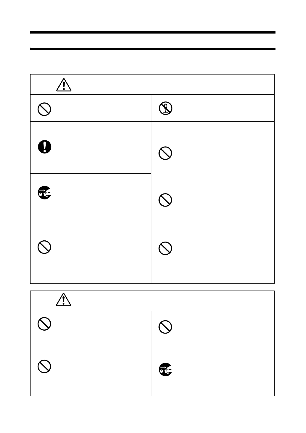
Safety Symbols
The following symbols are used in this manual to prevent accidents which may occur as result of
incorrect use of the instrument.
Denotes a sentence regarding a safety warning or note.
Read the sentence carefully to ensure safe and correct use.
Denotes a prohibited operation.
The operation must never been performed.
Denotes an instruction.
The instruction must be strictly adhered to.
Denotes a prohibited operation.
Never disassemble the instrument.
Denotes an instruction.
Disconnect the AC power cord from the AC outlet.
Trademarks
• Windows
• Bluetooth
®
is a registered trademark of Microsoft Corporation in the United States and other countries.
®
is a registered trademark of Bluetooth SIG, Inc.
Page 5
Safety Precautions
To ensure correct use of this instrument, read the following points carefully and adhere to them. After
you have read this manual, keep it in a safe place where it can be referred to anytime a question arises.
WARNING
Do not use the instrument in places
where flammable or combustible gases
(gasoline etc.) are present. Doing so
may cause a fire.
Always use the AC adapter supplied as
a standard accessory or the optional AC
adapter, and connect it to an AC outlet
of the rated voltage and frequency. If an
AC adapter other than those specified by
KONICA MINOLTA SENSING is
used, it may result in damage to the unit,
fire or electric shock.
If the instrument will not be used for a
long time, disconnect the AC adapter
from the AC outlet. Accumulated dirt or
water on the prongs of the AC adapter’s
plug may cause a fire and should be
removed.
Take special care not to allow liquid or
metal objects to enter the instrument.
Doing so may cause a fire or electric
shock. Should liquid or metal objects
enter the instrument, turn the power
OFF immediately, disconnect the AC
adapter from the AC outlet (or remove
the batteries if they are being used), and
contact the nearest KONICA
MINOLTA SENSING-authorized
service facility.
(Failure to adhere to the following points may result
in death or serious injury.)
Do not disassemble or modify the
instrument or the AC adapter. Doing so
may cause a fire or electric shock.
The instrument should not be operated if
it is damaged or the AC adapter is
damaged, or if smoke or odd smells
occur. Doing so may result in a fire. In
such situations, turn the power OFF
immediately, disconnect the AC adapter
from the AC outlet (or remove the
batteries if they are being used) and
contact the nearest KONICA MINOLTA
SENSING-authorized service facility.
Do not insert or disconnect the AC
adapter with wet hands. Doing so may
cause electric shock.
Do not dispose of batteries in fire, short
their terminals, apply heat to them, or
disassemble them. Also, do not recharge
them (if they are not chargeable). Doing
so may cause explosion or heat
generation, resulting in fire or injury.
CAUTION
Do not perform measurement with the
specimen measuring port directed
towards your face. Doing so may
damage your eyes.
Do not use batteries other than those
specified by KONICA MINOLTA
SENSING. When installing batteries in
the instrument, make sure that they are
correctly oriented according to the (+)
and (-) marks. Failure to adhere to these
instructions may cause batteries to
explode or leak electrolyte, resulting in
fire, injury or air pollution.
(Falling to adhere to the following points may result in
injury or damage to the instrument or other property.)
Do not place the instrument on an
unstable or sloping surface. Doing so
may result in its dropping or overturning,
causing injury. Be careful not to drop the
instrument when carrying it.
When using the AC adapter, make sure
that the AC outlet is located near the
instrument and that the AC adapter can
be connected to and disconnected from
the AC outlet easily.
E-1
Page 6
Introduction
Thank you for purchasing the CM-700d/600d.
This is a precise, lightweight and compact spectrophotometer developed for color and color difference
measurement of reflective objective colors in various industries.
Packing materials of the product
Be sure to keep all packing materials used for shipping the product (cardboard box, cushioning
material, plastic bags, etc.).
The CM-700d/600d is a precision measuring instrument. When transporting the instrument to a
service facility for maintenance or for other reasons, be sure to use the packing materials to minimize
shock or vibration.
If the packing materials are lost or damaged, contact a KONICA MINOLTA SENSING-authorized
service facility.
Notes on Use
Operating Environment
• Use the CM-700d/600d at ambient temperature between 5°C and 40°C and relative humidity 80% or less (at
35°C) with no condensation.
Be sure to use the instrument within this range. Do not use it in areas of rapid temperature changes.
• Do not leave the CM-700d/600d in direct sunlight or near sources of heat, such as stoves etc. The internal
temperature of the instrument may become much higher than the ambient temperature in such cases.
• Do not use the CM-700d/600d in areas where dust, cigarette smoke or chemical gases are present. Doing so
may cause deterioration in performance or a breakdown.
• Do not use the CM-700d/600d near equipment which produces a strong magnetic field (such as speakers etc.).
• The CM-700d/600d belongs to installation category II products (equipment which is powered by an AC
adapter connected to commercially available power).
• The CM-700d/600d belongs to pollution level 2 products (equipment which may cause temporary electrical
hazards due to contamination or condensation or products which are used in such an environment).
• Do not use the CM-700d/600d at altitudes higher than 2000 m.
• The CM-700d/600d and the AC adapter supplied as a standard accessory have been designed exclusively for
indoor use. They should never be used outdoors because rain or other factors may damage the instrument.
Measurement
• When using the instrument upside-down, make sure no dirt or dust get into the specimen measuring port.
• When using the instrument for long periods of time, the displayed value may change depending on changes in
the environment. Therefore, in order to achieve accurate measurements, we recommend that white calibration
be done regularly using the White Calibration Cap.
White Calibration Cap
• The White Calibration Cap must be used in combination with the instrument that bears the same pairing number.
•
The calibration data for the White Calibration Plate attached to the White Calibration Cap was measured at 23°C.
To achieve the highest accuracy when measuring absolute values (colorimetric values), calibration and
measurement should be performed at 23°C.
• Do not allow the White Calibration Plate to get scratched or stained.
• When not using the White Calibration Cap, invert it so that the White Calibration Plate is not exposed to
ambient light.
• When the White Calibration Cap is attached to the instrument, do not hold on to the White Calibration Cap to
move the instrument. The cap may become detached from the instrument, causing the instrument to fall and
become damaged.
Target Mask
• Do not touch the Target Mask’s inner surface by hand, scratch it or make it dirty.
• When not in use, Target Masks should be stored in the cardboard box used for shipment or in the optional hard
case so that they will not be exposed to ambient light.
E-2
Page 7
Power Source
• Make sure that the power switch is set to OFF (“ ”) when the CM-700d/600d is not in use.
• The CM-700d/600d can be powered from either the AC adapter (AC-A305) or AA-size alkaline or nickelmetal-hydride rechargeable batteries. Note, however, that you cannot use this AC adapter to charge the nickelmetal-hydride rechargeable batteries installed in the instrument.
• Always use the AC adapter supplied as a standard accessory (AC-A305) and connect it to an AC outlet of the
rated voltage and frequency. Use an AC power supply of the rated supply voltage (within ±10%).
System
• Do not subject the CM-700d/600d to strong impact or vibration. Doing so may cause deterioration in
performance or a breakdown.
• Since the specimen measuring port and integrating sphere are extremely precise optical components, great
care should be taken to prevent them getting dirty or exposing them to impact.
• When not in use, the instrument must be stored with the White Calibration Cap being attached.
• The CM-700d/600d may cause interference if used near a television, radio, etc.
• When the instrument is exposed to strong external static electricity, the LCD may go blank or the measurement
result may not be displayed properly. If the instrument is communicating with an external device, the
communication may be interrupted. In these cases, turn the power OFF and then turn it ON again. If black
smudges appear on the LCD, wait until they disappear naturally.
• When turning the power OFF and then ON again, wait several seconds after turning the power OFF.
Backup Battery
• Measured data and various settings are stored in the memory backed up by batteries. The backup batteries are
automatically charged during operation of this instrument, and can retain the contents of the memory for 5
months if they have been fully charged. At the time of purchase, the backup battery may not be fully charged.
To charge the backup battery, set the power switch to ON. Charging of the backup battery is performed
continuously while the instrument is switched on, even while the instrument is being used. Full charging is
completed in 24 hours, and there is no danger of overcharging.
• It is recommended to keep a backup for your important data on another recording medium using the optional
Color Data Software SpectraMagic™ NX (CM-S100w).
Note
• The backup batteries' model number is ML2020 (3 V).
• Do not try to replace the backup batteries by yourself. Contact a KONICA MINOLTA SENSING-authorized
service facility.
Notes on Storage
• The CM-700d/600d should be stored at temperatures between 0°C and 45°C, and at a relative humidity of 80%
or less (35°C) without condensation. Do not store the instrument in areas subject to high temperatures, high
humidity, sudden changes in temperature, or where freezing or condensation may occur, because these
circumstances may cause a breakdown. It is recommended to store the CM-700d/600d with a drying agent
(such as silica gel) at a temperature around 20°C.
• Do not leave the CM-700d/600d inside a car such as in the cabinet or trunk. Otherwise, the temperature and/
or humidity may exceed the allowable range for storage during midsummer or midwinter, resulting in a
breakdown.
• Keep the packing materials used for shipment and use them to transport the CM-700d/600d. This protects the
instrument from sudden changes in temperature, vibration, and shock.
• Do not store the CM-700d/600d in areas where dust, cigarette smoke or chemical gases are present. Doing so
may cause deterioration in performance or a breakdown.
• Entry of dust into the specimen measuring port will hinder accurate measurement. When the instrument is not
in use, you must attach the White Calibration Cap to the instrument to prevent the entry of dust into the
integrating sphere through the specimen measuring port.
E-3
Page 8

• The White Calibration Plate attached to the White Calibration Cap may become discolored if left exposed to
light. Therefore, make sure that the cap is inverted when it is not in use so that the White Calibration Plate is
not exposed to ambient light.
• The Target Masks may discolor if they are left exposed to light. When they are not in use, keep them in a safe
place to prevent exposure to light and to protect them from scratches and dust.
• Be sure to keep all packing materials (cardboard box, cushioning material, plastic bags, etc.). They can be used
to protect the instrument during transportation to the service facility for maintenance (re-calibration etc.).
• If you are not going to use the CM-700d/600d for more than two weeks, the batteries must be removed. If the
batteries are left in the instrument, battery electrolyte may leak and damage the instrument.
Notes on Cleaning
• If the CM-700d/600d becomes dirty, wipe it with a soft, clean dry cloth. Never use solvents such as thinner or
benzene.
• If the White Calibration Plate attached to the White Calibration Cap becomes dirty, wipe it gently with a soft,
clean and dry cloth. If dirt is difficult to remove, wipe it off with a cloth dampened with commerciallyavailable lens cleaning solution. Then remove the solution with a cloth dampened with water, and leave the
plate to dry.
• If the inner surface of the Target Masks or the inside of the integrating sphere get dirty, contact a KONICA
MINOLTA SENSING-authorized service facility.
• Should the CM-700d/600d break down, do not try to disassemble and repair it by yourself. Contact a KONICA
MINOLTA SENSING-authorized service facility.
Disposal Method
• When disposing of used batteries, insulate the terminals with insulating tape etc. If the terminals of the battery
come into contact with metal objects, heat generation, explosion or fire may result.
• Make sure that the CM-700d/600d, its accessories and used batteries are either disposed of or recycled
correctly in accordance with local laws and regulations.
E-4
Page 9

E-5
Page 10

Contents
Safety Precautions ......................................................................................................................... E-1
Introduction ................................................................................................................................ E-2
Notes on Use .............................................................................................................................. E-2
Notes on Storage ........................................................................................................................ E-3
Notes on Cleaning ...................................................................................................................... E-4
Disposal Method ........................................................................................................................ E-4
Conventions ............................................................................................................................... E-8
Chapter 1 Before Using the Instrument
Accessories ...................................................................................................................................... E-10
Standard Accessories ................................................................................................................. E-10
Optional Accessories ................................................................................................................. E-11
Names and Functions of Parts ...................................................................................................... E-12
Preparation .................................................................................................................................... E-14
White Calibration Cap CM-A177 .............................................................................................. E-14
Attaching/Removing a Target Mask .......................................................................................... E-15
Cleaning Parts ............................................................................................................................ E-16
Attaching Wrist Strap to the Instrument .................................................................................... E-17
Inserting the Batteries ................................................................................................................ E-18
Connecting the AC Adapter ....................................................................................................... E-19
Turning Power ON/OFF ............................................................................................................ E-20
System Diagram ............................................................................................................................. E-21
Items You Must Know .................................................................................................................. E-22
Initial Settings of the CM-700d/600d ........................................................................................ E-22
Control Panel ............................................................................................................................. E-22
Battery Alarm ............................................................................................................................ E-24
Data Saving ................................................................................................................................ E-24
Pairing Number .......................................................................................................................... E-24
Chapter 2 Preparation for Measurement
Flow of Measurement .................................................................................................................... E-26
Calibration ..................................................................................................................................... E-27
Zero Calibration ......................................................................................................................... E-27
White Calibration ....................................................................................................................... E-29
User Calibration.......................................................................................................................... E-31
Condition Setting ........................................................................................................................... E-32
Setting the Display Conditions ................................................................................................... E-32
Setting the Measurement Conditions ......................................................................................... E-42
Color Difference Target Color Data Operation ......................................................................... E-47
Setting a Target Color................................................................................................................. E-47
Target Color Menu ..................................................................................................................... E-48
Registering Conditions (Cond) ..................................................................................................... E-56
Naming a Condition ................................................................................................................... E-58
Setting the Default Color Difference Tolerance (Tolerance (Def.)) .......................................... E-59
Selecting Color Difference Tolerances ...................................................................................... E-62
Deleting the Default Color Difference Tolerance Setting ......................................................... E-63
Naming the Color Difference Tolerance Setting ....................................................................... E-64
E-6
Page 11

Other Settings ................................................................................................................................ E-66
Setting the Display Language .................................................................................................... E-66
Setting the Date and Time ......................................................................................................... E-67
Setting the Power Save Mode .................................................................................................... E-70
Initialization ............................................................................................................................... E-72
Chapter 3 Measurement
Measurement .................................................................................................................................. E-74
Displaying the Measurement Results ........................................................................................... E-75
Measured Data ........................................................................................................................... E-75
Pass/Fail Judgment .................................................................................................................... E-76
Color Difference Graph ............................................................................................................. E-76
Spectral Reflectance Graph ....................................................................................................... E-77
Switching the Display Contents of the Measurement Results ................................................... E-78
Measured Data Operation ............................................................................................................ E-81
Print ............................................................................................................................................ E-82
Delete ......................................................................................................................................... E-82
Edit Name .................................................................................................................................. E-83
Setting the List (List) ................................................................................................................. E-84
Auto Target ................................................................................................................................ E-84
Delete All ................................................................................................................................... E-85
Chapter 4 Other Functions
Average Measurement .................................................................................................................. E-88
Manual Averaging ..................................................................................................................... E-88
Auto Averaging .......................................................................................................................... E-90
Pass/Fail Judgment for Color Difference .................................................................................... E-91
Pass/Fail Judgment Based on Tolerances .................................................................................. E-91
Connecting to an External Device ................................................................................................ E-94
Connecting a Personal Computer .............................................................................................. E-94
Connecting a Printer .................................................................................................................. E-98
Displaying the Instrument Information ...................................................................................... E-1
Chapter 5 Troubleshooting
Error Messages .............................................................................................................................. E-108
Troubleshooting ............................................................................................................................. E-111
Chapter 6 Appendix
Principles of Measurement ........................................................................................................... E-114
Illuminating/Viewing System .................................................................................................... E-114
Illumination Area and Measurement Area ................................................................................. E-115
Simultaneous SCI/SCE Measurement ....................................................................................... E-115
Communication Mode ............................................................................................................... E-115
Initial Settings ............................................................................................................................ E-116
Specifications .................................................................................................................................. E-117
Dimensions ..................................................................................................................................... E-119
06
E-7
Page 12
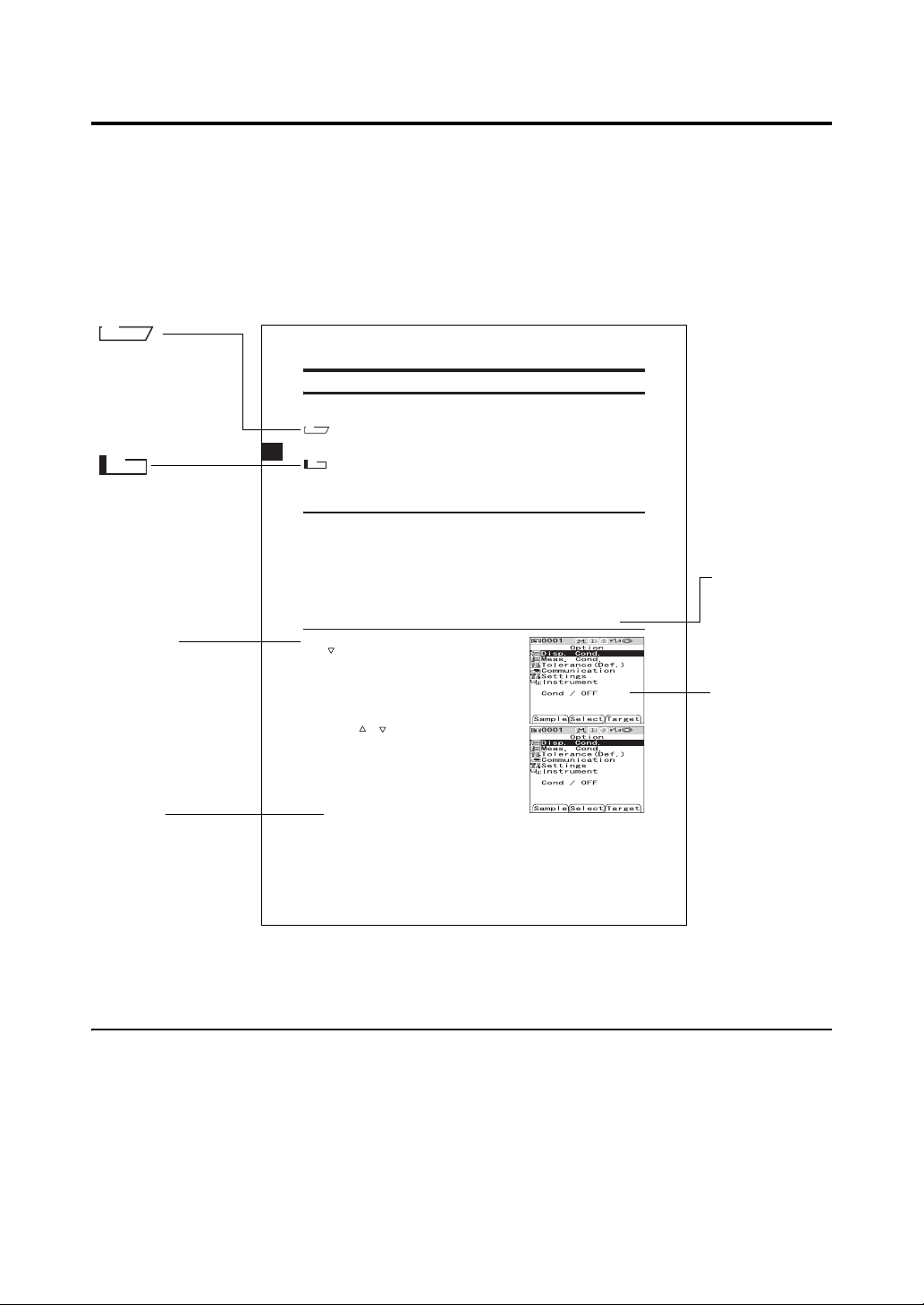
Conventions
This manual describes how to safely operate the CM-700d/600d using a specific procedure to perform
measurement.
• Page layout
Symbols used in this manual are explained below.
*Note that the page shown in the illustration is for explanatory purposes only, and is not an actual page
from this manual.
M
emo
Gives useful
Information and
additional
explanations.
Note
Gives the points that
you should know to
perform operations
correctly. Make sure
that you read the notes.
Procedure
Shows the operating
procedure.
Settings
Gives the range and
explanation of the
values to be set in this
screen.
Condition Setting
The CM-700d/600d requires condition settings (display and measurement conditions) before
measurement can be started.
M
emo
To configure condition settings, select “Disp. Cond.” (display conditions) or “Meas. Cond.” (measurement
conditions) from the <Option> screen to open an appropriate screen.
N
ote
The results for “Difference”, “Abs. & Diff.”
specified.
Setting the Display Conditions
To set the display conditions, select “Disp. Cond.” on the <Option> screen.
You can select or specify the following seven items as the display conditions:
• Disp. Type: Specify items to be displayed as measurement results.
• Color Space: Select a color space to be used.
• Equation: Select a color difference formula to be used.
• Color Index: Select an index (WI, YI, etc.) to be used.
• Observer: Select a measuring angle from 2° or 10°
• Illuminant 1: Select an illuminant used to measure colorimetric data.
• Illuminant 2: Select a secondary illuminant used for MI (metamerism index) calculation, etc.
[Setting Procedure]
Hold down the [MENU] button and press the
1
button of the cross key.
The <Option> screen is displayed.
Use the or button of the cross key to
2
move the cursor to "Disp. Cond." and then
press the [SAVE/SEL] button.
The <Disp. Cond.> screen is displayed.
Settings
Absolute: Display the absolute value of the colorimetric data.
Difference:
Display the color difference from the target color. The measured data which failed the pass/fail judgment
based on the specified tolerances will be highlighted in red.
Abs. & Diff.:
Display the absolute value and the color difference from the target color. The measured data which
failed the pass/fail judgment based on the specified tolerances will be highlighted in red.
E-32
and “Graph Diff.” will be displayed only when the target color has been
Start the procedure from the <Disp. Cond.> screen.
Start screen
Shows the screen
from which
operation must
be started.
Screen
Shows the
contents of the
current screen
when the given
operation is
carried out.
For the version of the instrument firmware
The version of the instrument firmware can be confirmed on the <Instrument> screen. For details, refer
to page E-106 “Displaying the Instrument Information” in this manual.
E-8
Page 13

Chapter 1
Before Using the Instrument
E-9
Page 14

Accessories
Standard and optional accessories are available with the instrument.
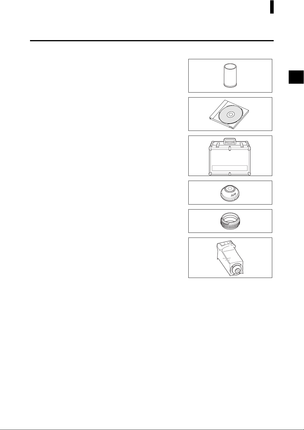
Standard Accessories
Make sure that all the following items are present.
White Calibration Cap CM-A177
(w/ white calibration data CD-R)
Target Mask
Used to switch the illumination area (specimen measuring port
size) according to the specimen.
Target Mask
Target Mask
Target Mask
Target Mask
M
emo
• The instrument is shipped with the CM-A178 Target Mask φ 8 mm
with plate (for MAV) being attached.
• The CM-A179 and CM-A181 Target Masks
not included in the package of the CM-600d.
AC Adapter AC-A305
Used to supply power from an AC outlet to the instrument.
Input: 100-240 V 50/60 Hz 24-38 VA
Output: 5 V 2 A
USB Cable IF-A17
Used to connect the instrument to a personal computer (PC).
4 AA-size alkaline dry batteries
φ
8 mm (w/ plate) CM-A178 <For MAV>
φ
3 mm (w/ plate) CM-A179 <For SAV>
φ
8 mm (w/o plate) CM-A180 <For MAV>
φ
3 mm (w/o plate) CM-A181 <For SAV>
φ
3 mm (for SAV) are
Wrist Strap CR-A73
E-10
Page 15
Optional Accessories
You may purchase the following accessories if necessary.
Zero Calibration Box CM-A182
Used to perform zero calibration.
Accessories
Color Data Software S
Used to operate the instrument from a PC for data processing and
file management.
Hard Case CM-A176
Used to store the instrument together with accessories.
*Do not use the hard case for transportation purposes.
Target Mask
Used to measure viscous or damp specimens.
Granular-Materials Attachment CM-A184
Used to contain paste or powder specimens to ensure
measurements under stable conditions.
Dust Cover Set CM-A185
Prevents foreign matters from entering the instrument in dusty
environments.
φ
pectraMagic™ NX CM-S100w
8 mm (with glass) CM-A183
Replacement Dust Cover (Polyolefin) CM-A186
E-11
Page 16
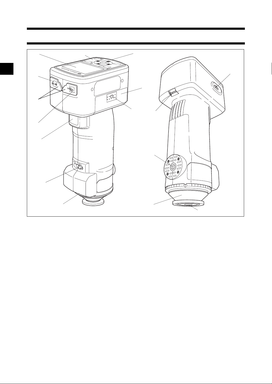
Names and Functions of Parts
10
11
12
9
16
13
1
3
5
4
6
8
2
7
1 LCD screen
Displays setting items, measurement results and messages.
2 Control panel
Used to switch screens or select/determine/save setting items.
For details, refer to page E-23 “Control Buttons”.
3 AC adapter terminal
When using the supplied AC adapter (CM-A305), connect the adapter’s plug to this terminal.
4 USB connection terminal
Used to connect the instrument to a PC with the supplied USB cable (IF-A17).
5 Connector protection covers
Protects the AC adapter terminal and USB connection terminal.
6 Measuring button
Push this button to perform calibration or measurement.
7 Pairing No. label
Shows the identification No. of the White Calibration Cap that can be used with the instrument.
14
15
E-12
Page 17

Names and Functions of Parts
8 Measurement area selector
Used to change the lens position according to the
measurement area.
M
emo
The CM-600d does not have this switch.
9 Battery chamber cover
The cover of the battery chamber. Four AA-size batteries must be set in the battery chamber with the
correct polarity alignment.
10 Battery chamber cover button
Press this button to open or close the battery chamber cover.
11 READY Lamp
Ready to measure (and fully charged) when green.
12 Power switch
Used to turn ON/OFF power. Setting this switch to “ ” turns the power OFF, and setting it to “|”
turns the power ON.
13 Tripod mount
14 Target Mask
Used to change the measurement area according to the measurement area selector setting. Selectable
from several types depending on the application.
15 Specimen measuring port
The port for measuring the specimen.The port size can be changed by changing the Target Masks.
Note
The measurement area cannot be changed with the CM-600d.
16 Strap holder
Used to attach the supplied Wrist Strap.
M
emo
For details of attaching Wrist Strap, refer to “Attaching Wrist Strap to the Instrument” (page E-17).
E-13
Page 18

Preparation
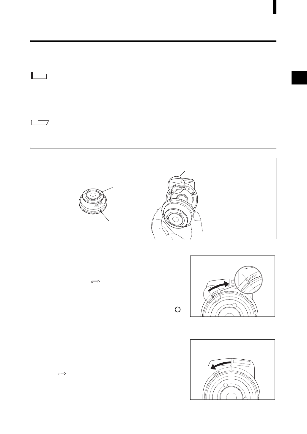
White Calibration Cap CM-A177
The instrument is shipped with a White Calibration Cap and white calibration data CD-R.
The White Calibration Cap has the structure shown below. It should be attached to the instrument before
white calibration.
Note
• The White Calibration Cap must be used in combination with the instrument that bears the same pairing number.
• When the White Calibration Cap is not in use, invert it so that the White Calibration Plate is not exposed to
ambient light or dust.
• When the CM-700d/600d is not in use, you must attach the White Calibration Cap to the instrument to prevent
the entry of dust into the integrating sphere through the specimen measuring port.
White Calibration Cap lock buttons
Latch
White
Calibration Plate
Attachment/Removal to/from the Instrument
• Attachment
1. Hold the instrument securely.
2. Squeeze the White Calibration Cap lock buttons,
place the White Calibration Cap on the Target Mask
of the instrument, and release the lock buttons to
secure the cap.
Note
Do not move the instrument by holding the White Calibration Cap. The
instrument may detach from the cap, possibly resulting in the
instrument falling and being damaged.
• Removal
1. While squeezing the White Calibration Cap lock
buttons, pull the cap out straight from the
instrument.
Pairing No.
Serial number of the
White Calibration Cap
E-14
Page 19
Preparation
Attaching/Removing a Target Mask
The CM-700d/600d must be used with a Target Mask conforming to the selected lens position and
measurement condition.
To attach/remove a Target Mask, follow the procedure given below.
Note
• When attaching/removing a Target Mask, be careful not to allow dirt or dust to enter the integrating sphere
though the specimen measuring port.
• Do not touch the white-coated inner surface of the integrating sphere, wipe it with a cloth or put an object inside it.
• Do not exert excessive force on the latch of the Target Mask. Doing so may damage the latch, disabling use of
the Target Mask.
M
emo
If a Target Mask is damaged, contact a KONICA MINOLTA SENSING-authorized service facility.
Attachment/Removal to/from the Instrument
Target Mask
The figure shows the φ 8 mm type (w/ plate) <For MAV>.
Plate
Cut in the outer edge
• Attachment
1. Place the Target Mask over the specimen measuring
port so that the cut in the outer edge of the Target
Mask is aligned with the starting point of the
positioning mark ( ) on the instrument.
2. Hold the outer edge of the mask, and turn it in the
direction of the arrow (clockwise). Turn the mask
until the cut in the outer edge is aligned with the “ ”
mark on the instrument and then secure the mask.
• Removal
Target Mask positioning mark
Section of the CM-700d/
600d to which the Target
Mask is attached.
1. Hold the outer edge of the mask, and turn it in the
opposite direction of the arrow (counterclockwise).
Turn the mask until the cut in the outer edge is
aligned with the starting point of the positioning
mark ( ) of the instrument.
2. Hold the outer edge of the mask and remove it.
E-15
Page 20
Preparation
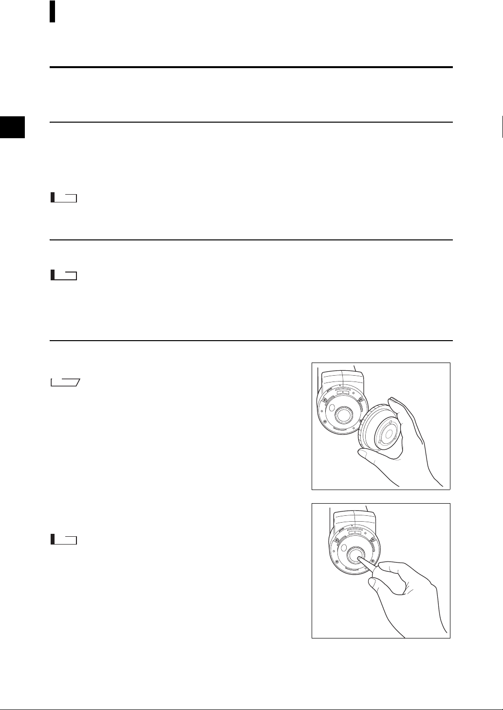
Cleaning Parts
This section explains how to clean the White Calibration Cap, Target Mask and the inside of the
integrating sphere.
White Calibration Cap
• When the White Calibration Plate becomes dirty, gently wipe the dirt off with a soft dry cloth. If the dirt is difficult
to remove, wipe it off with a cloth dampened with commercially available lens cleaning solution. Then remove
the solution with a cloth dampened with water, and leave the plate to dry.
• When parts other than the White Calibration Plate become dirty, lightly wipe the dirt off with a cloth dampened
with water or soapy water. Never use solvents such as thinner or benzene.
Note
Be careful not to scratch the White Calibration Plate.
Target Mask
Use a blower to remove dirt and dust from the Target Masks.
Note
Do not touch the inner surface of the Target Masks with your fingers or wipe them with a cloth to remove dust.
If the inside is so dirty that dirt cannot be removed with a blower, contact the nearest KONICA MINOLTA
SENSING-authorized service facility.
Inside the Integrating Sphere
1. Remove the Target Mask.
M
emo
For the procedure of removing the Target Mask, refer to page E-15
“Attaching/Removing a Target Mask”.
2. Use a blower to remove dirt and dust from the
integrating sphere.
Note
Do not touch the white-coated inner surface of the integrating sphere,
wipe it with a cloth or put an object inside it. If the inside is so dirty that
dirt cannot be removed with a blower, contact the nearest KONICA
MINOLTA SENSING-authorized service facility.
E-16
Page 21
Preparation
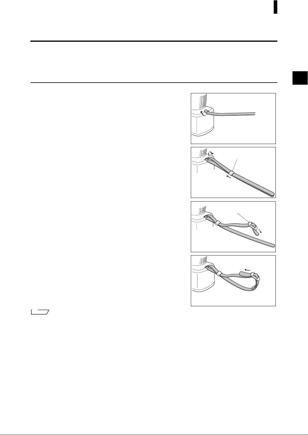
Attaching Wrist Strap to the Instrument
When measuring by hand, attach Wrist Strap and put your arm through Wrist Strap to prevent dropping
of the instrument.
[Procedure]
Pass one end of Wrist Strap through the strap
1
holder of the instrument.
Pass other end of Wrist Strap through the ring,
2
and pass the strap that passed through the strap
holder through the ring too.
Ring
Pass one end of Wrist Strap that passed through
3
the ring through the buckle.
Pass other end of the strap through the buckle
4
from the other side.
M
emo
If necessary, after passing the arm through the strap, move the position of the ring so that the strap is snug your arm.
Buckle
E-17
Page 22

Preparation
Inserting the Batteries
For the CM-700d/600d, the supplied AC adapter (AC-A305) or four AA-size batteries (alkaline or
nickel-metal-hydride rechargeable batteries) must be used as a power supply. Use either the AC adapter
or batteries according to your application.
Note
• Do not use manganese batteries.
• If you are not going to use the CM-700d/600d for more than two weeks, the batteries must be removed. If the
batteries are left in the instrument for a long time, battery electrolyte may leak and damage the instrument.
• Do not use batteries of different types or mix new batteries with old ones. Doing so may result in battery
explosion or shorter battery life.
• Do not touch or short-circuit the terminals inside the battery chamber. Doing so may result in breakdown of
the instrument.
[Procedure]
Make sure that power is OFF (Power switch is set
1
to “ ”).
Press the battery chamber cover button on the
2
side of the instrument and slide the cover
downward to open it.
Place four AA-size batteries in the battery
3
chamber. Make sure that the batteries are placed
in the correct direction.
Align the grooves of the cover with the guides on
4
the edge of the battery chamber opening. Press
down lightly on the cover and slide it upward to
close it.
E-18
Page 23

Preparation
Connecting the AC Adapter
M
emo
When the external output terminal is used for data communication or printing, more power will be required. In this
case, it is recommended to use the AC adapter (AC-A305) rather than batteries.
Note
• To supply AC power to the instrument, always use the AC adapter (AC-A305) supplied with the instrument.
• Before connecting or disconnecting the AC adapter jack or plug, make sure that the instrument is turned OFF.
[Operating Procedure]
Make sure that power is OFF (Power switch is set
1
to “ ”.).
Open the connector protection cover of the AC
2
adapter terminal on the instrument.
Connect the AC adapter connector jack to the AC
3
adapter terminal.
Insert the AC adapter power plug to an AC outlet
4
(100 to 240 VAC, 50-60 Hz).
E-19
Page 24

Preparation
Turning Power ON/OFF
[Operating Procedure]
Turning power ON
Slide the Power switch to the “|” position.
1
The power will be turned ON (energized).
[Operating Procedure]
Turning power OFF
Slide the Power switch to the “ ” position.
1
The power will be turned OFF.
Power Save Function
The CM-700d/600d features a power save function which activates the power save mode when none of
the measuring and control buttons is operated for a specified period of time. In the power save mode, the
screen display is turned off and the flash circuit will not be charged.
You can return to the normal mode by pressing any of the measuring or control buttons.
M
emo
The period of time before the power save mode is activated can be set on the <Option> screen. For details, refer to
page E-70 “Setting the Power Save Mode”.
Note
The power save function is factory-set to OFF.
E-20
Page 25

System Diagram
Standard accessories
Optional accessories
Hard Case
CM-A176
* For storage
Personal computer
(Commercially
available)
USB Cable (2 m)
IF-A17
Color Data Software
CM-S100w
AC Adapter
AC-A305
White Calibration
Cap
CM-A177
CM-700d/600d
CM-600d
φ 8 mm
CM-A178
(w/ plate)
φ 8 mm
CM-A180
(w/o plate)
CM-700d
φ 3 mm
CM-A179
(w/ plate)
φ 3 mm
CM-A181
(w/o plate)
Wrist Strap
CR-A73
Target Mask
φ 8 mm (with glass)
CM-A183
Dust Cover Set
CM-A185
Replacement Dust Cover
(Polyolefin)
CM-A186
Zero Calibration Box
CM-A182
Granular-Materials
Attachment
CM-A184
E-21
Page 26
Items You Must Know
Initial Settings of the CM-700d/600d
When the instrument is turned ON, the <Calibration> screen will appear automatically in English. For
normal measurement, you do not need to change the initial settings.
It is recommended that you check the date and specify the power save mode in the <Option> screen
before using the instrument.
The display language can be selected from seven languages including Japanese.
For details, refer to page E-66 “Other Settings”.
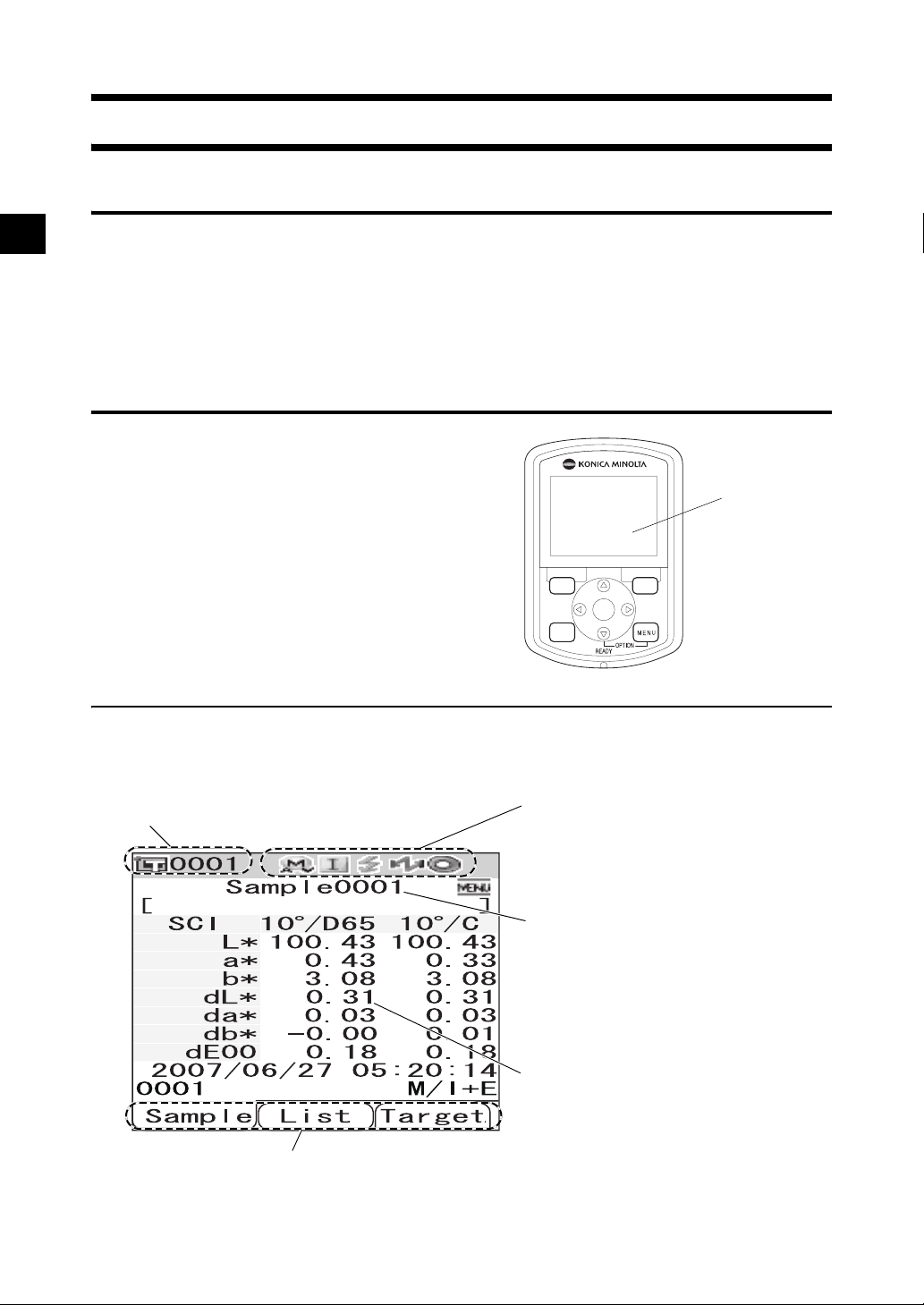
Control Panel
The top of the CM-700d/600d contains the LCD
screen on which the instrument displays
measurement results and messages, and the control
buttons which are used to set measurement options or
to change displays.
SAMPLE TARGET
SAVE
SEL
CAL
LCD
screen
Screen Display (LCD Screen)
The LCD screen displays measurement settings, measurement results and messages. It also indicates the
status of the instrument with icons.
The basic screen layout is shown below.
Target color No.
The functions assigned to the [SAMPLE], [SAVE/SEL] and [TARGET] buttons
are displayed respectively.
Status icons
The current settings and status of the
instrument are indicated with icons.
* For details, refer to the next page.
The screen title is displayed.
Measured values and setting
items are displayed.
E-22
Page 27

Items You Must Know
Status Icons
Status icon Description (Status) Meaning
Measurement area (Measurement
/
area selector setting)
* The CM-700d shows either the MAV or SAV icon. The CM-600d shows
MAV/SAV
only the MAV icon.
/ / Specular component mode setting SCI/SCE/I + E (SCI + SCE)
/ Bluetooth capability setting ON/OFF
Zero calibration required/White
/ / Calibration necessity
calibration required/User calibration
required
/ White calibration after power-on Performed/Not performed
/ Flash circuit charging Completed/Not completed
Control Buttons
Use these buttons to set items or change screens according to the guide on the LCD screen.
1
4
1 [SAMPLE] button:
Press this button to display the <Sample>
screen.
2 [TARGET] button:
Press this button to display the <Target>
screen.
3 [SAVE/SEL] button:
Use this button to determine the item indicated
by the cursor or to save the setting.
When the <Sample> or <Target> screen is
displayed, use this button to switch between
the detail display and list display.
4 [CAL] button:
SAMPLE TARGET
SAVE
SEL
CAL
5 [MENU] button:
Press this button to display the <Menu>
screen.
The screens and setting items for which menu
setting is available are indicated with
(MENU mark) at the top of the screen.
You can display the <Option> screen by
pressing the [MENU] button while holding
down the button of the cross key.
6 Cross key (///):
Use this key to move the cursor on the screen
or to change the selected value.
To determine the item indicated by the cursor,
press the [SAVE/SEL] button.
2
3
6
5
Press this button to display the <Calibration>
screen.
M
emo
The [SAMPLE], [SAVE/SEL] and [TARGET] buttons may be assigned different functions depending on the screen.
In this case, the guidance at the bottom of the screen indicates the current functions (Edit, etc.).
E-23
Page 28

Items You Must Know
Example of assigned functions
For example, when the screen shows the guidance
Edit
SEL] and [TARGET] buttons are assigned with the Edit, Save and
Back functions respectively. In this manual, when the button
name and the function assigned to the button are different, the
button name and function are described as “the [SAMPLE] (Edit)
button” or “[TARGET] (Back) button”.
Save Back
, the [SAMPLE], [SAVE/
Battery Alarm
The CM-700d/600d can be powered from the standard AC adapter (AC-A305) or AA-size alkaline or
nickel-metal-hydride rechargeable batteries. When the instrument is used with batteries, two types of
battery alarm indication will appear when battery power level is low. When the battery power is
sufficient, no battery alarm indication is displayed.
(Low battery indication)
When this indication appears, new batteries or the AC adapter should be prepared in the near future.
Even with this indication displayed, measurements are still possible.
If you continue using the instrument with the low battery indication being displayed, ER002 (low
battery voltage error) is displayed. When this error is displayed, replace the batteries immediately
with new ones or connect the AC adapter.
Data Saving
Data used with this instrument are saved automatically. The white calibration data stored in the internal
memory after you perform white calibration is retained even after the instrument is turned off.
Pairing Number
In addition to individual serial numbers, the instrument and White Calibration Cap bear 5-digit numbers
called “pairing number”. Before starting white calibration, confirm that the instrument and White
Calibration Cap have the same pairing number.
White Calibration Cap
Serial number of the
White Calibration Cap
CM-700d/600d
Pairing number
The instrument and White Calibration Cap to be used together must have the same
pairing number.
E-24
Page 29

Chapter 2
Preparation for Measurement
E-25
Page 30
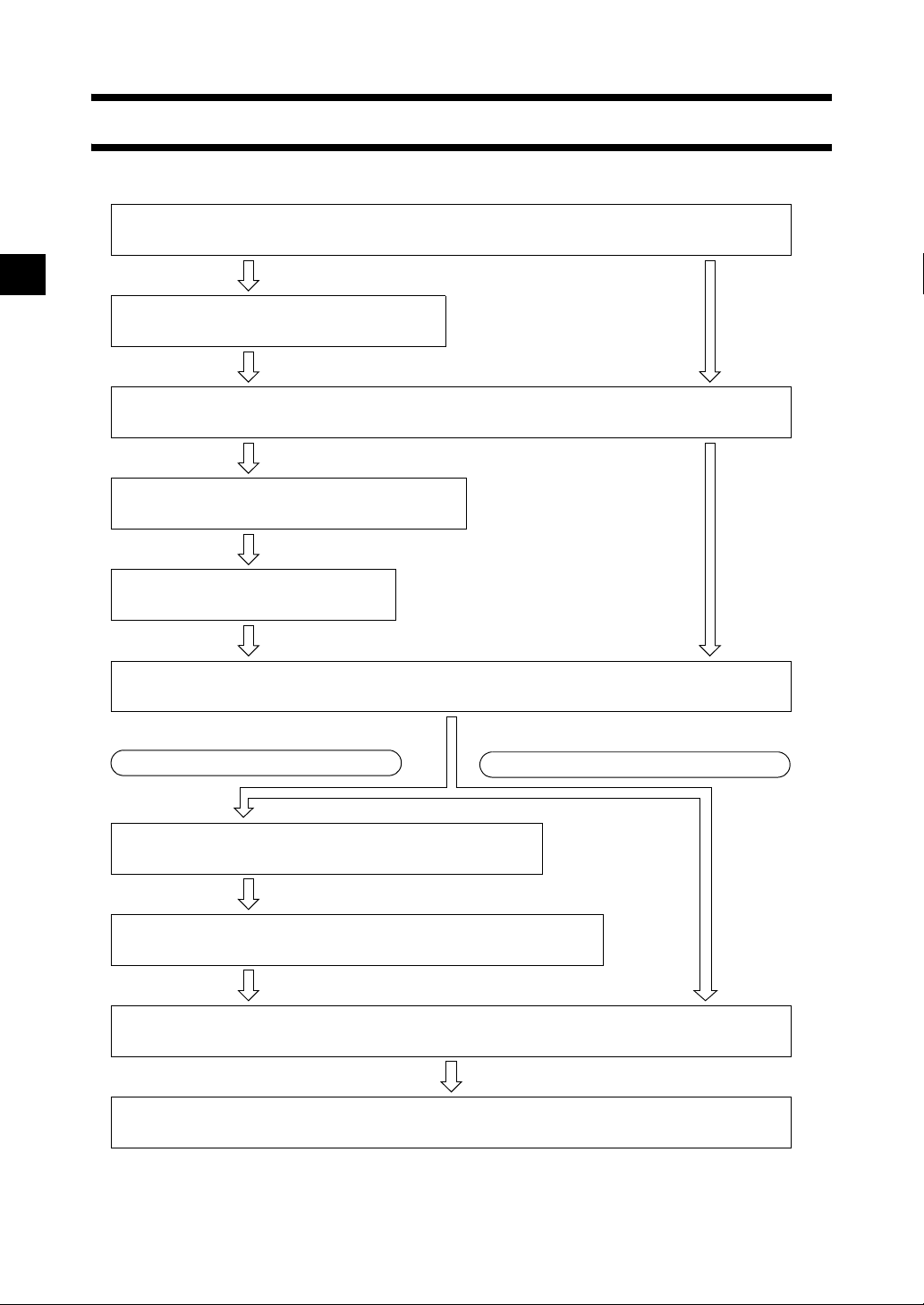
Flow of Measurement
■ Optional settings ■ Basic procedure
Turning Power ON/OFF (page E-20)
Setting the Display Language (page E-66)
Registering Conditions (Cond) (page E-56)
Attaching/Removing a Target Mask (page E-15)
Zero Calibration (page E-27)
White Calibration (page E-29)
When Checking Color Difference
* Perform this step if necessary
* Perform this step only if necessary,
such as after initialization.
such as after initialization.
* Perform this step if
necessary according to the
measurement conditions.
When Not Checking Color Difference
Color Difference Target Color Data Operation (page E-47)
Target Color Menu (page E-48)
Measurement (page E-74)
Completion of Measurement
E-26
Page 31

Calibration
Zero Calibration
Since the CM-700d/600d stores the data of the zero calibration performed at the factory, it is unnecessary
to repeat the zero calibration every time you turn ON the instrument. However, if the measurement
conditions change greatly, or if you use the optional dust cover set or Target Mask
you need to perform zero calibration before white calibration.
M
emo
• The effects of stray light inside the measuring part (i.e. light generated due to the flare characteristics of the optical
system) will be compensated for automatically by the zero calibration data.
• The amount of stray light may change because of dust or dirt which has collected in the optical system, humidity,
repeated operation, or vibration and shock exerted on the instrument. In this case, performing zero calibration
periodically is recommended.
• When I + E (SCI + SCE) is specified as the specular component mode (refer to page E-43 “Mode”), clicks caused
by opening and closing the optical trap may be heard during the measurement.
Note
• If the instrument is not used for long periods of time, the zero calibration data stored in the instrument may be
lost. If the data is lost, zero calibration must be performed again.
• When the instrument is used for the first time after purchase at a given measurement area setting (MAV or
SAV; SAV is available on CM-700d only), zero calibration must be performed.
• If you performed zero calibration using the optional dust cover set or Target Mask
must perform zero calibration again before starting measurement using the standard Target Mask.
φ
8 mm (with glass),
φ
8 mm (with glass), you
[Setting Procedure]
Confirm the type of attached target mask and the setting of the measurement area
1
selector of the instrument.
Turn the instrument ON.
2
The <Calibration> screen is displayed.
Note
Check the status icons displayed at the top of the screen to
verify that the lens position (MAV/SAV) icon is correct for
the measurement area selector setting and for the type of
attached Target Mask.
• If a different screen is displayed, press the [CAL] button.
E-27
Page 32

Calibration
Use the button of the cross key to move the
3
cursor to “Zero Cal.”
Direct the specimen measuring port to midair.
4
• Do not direct the specimen measuring port toward a light
source (including illumination such as a fluorescent lamp).
• Keep the specimen measuring port more than 1 m away
from any reflective items (hands, desks, walls etc.).
M
emo
Use of the optional Zero Calibration Box CM-A182 ensures
proper zero calibration.
Make sure that (Ready to measure) is
5
displayed or Ready lamp is green, and then
press the measuring button.
Zero calibration will be performed.
The Xe lamp flashes five times for each SCI and SCE
measurement.
During zero calibration, the screen shows the number of
flashes performed.
m
1
E-28
When zero calibration is finished, the screen returns to the
<Calibration> screen.
M
emo
When the screen is turned OFF by the power save function, press any of the measuring or control buttons to
turn ON the screen, confirm that (Ready to measure) is displayed or Ready lamp is green, and then press
the measuring button.
Note
• After zero calibration finished, perform white calibration. Go to step 3 of “White Calibration” on page
E-29.
• Even though you performed white calibration after turning ON the power, you need to perform it again
if you performed zero calibration after the first white calibration.
Page 33

Calibration
White Calibration
White calibration must be performed prior to start of measurement after the power is turned ON for the
first time after purchase at the current settings.
When white calibration finishes, <white calibration completed icon> is displayed.
Once white calibration is completed, measurement is possible without white calibration when the
instrument is turned ON the next time. However, the measurement result is not accurate.
M
emo
• The calibration data for the White Calibration Cap supplied with the instrument are stored in the instrument.
• Although the white calibration results stored in the internal memory are retained even after the instrument is turned
off, it is recommended that you repeat white calibration each time you switch the power back on.
• The reading may fluctuate slightly due to changes in the ambient temperature or due to heat generation caused by
repeated operation of the instrument. In this case, make sure to perform white calibration regularly.
• When I + E (SCI + SCE) is specified as the specular component mode (refer to page E-43 “Mode”), clicks caused
by opening and closing the optical trap may be heard during the measurement.
Note
• White calibration must be performed at the same temperature as the one at which measurement will be
performed.
• Before starting white calibration, make sure that the instrument is sufficiently acclimatized to the ambient
temperature.
• Whenever the measurement area setting has been changed between MAV and SAV, white calibration must be
performed.
[Setting Procedure]
Confirm the type of attached target mask and the setting of the measurement area
1
selector of the instrument.
Turn the instrument ON.
2
The <Calibration> screen is displayed.
Note
Check the status icons displayed at the top of the screen to
verify that the lens position (MAV/SAV) icon is correct for
the measurement area selector setting and for the type of
attached Target Mask.
• If a different screen is displayed, press the [CAL] button.
M
emo
• The <Calibration> screen shows two items: “Zero Cal.”
and “White Cal.” The date of the last calibration is
displayed under each item. If no calibration has been
performed yet, “None” is displayed.
• Under “White Cal.”, the serial number of the White
Calibration Cap to be used for the instrument is displayed.
If necessary, use the button of the cross
3
key to move the cursor to “White Cal.”
E-29
Page 34

Calibration
Properly attach the White Calibration Cap,
4
which has the same pairing number as the
instrument.
Make sure that (Ready to measure) is
5
displayed or Ready lamp is green, and then
press the measuring button.
White calibration will be performed.
The Xe lamp flashes five times for each SCI and SCE
measurement.
During white calibration, the screen shows the number of
flashes performed.
When white calibration finishes, the screen returns to the
<Calibration> screen.
Note
The instrument contains the data for the White Calibration Cap which has the same pairing number.
Therefore, you must use the instrument and corresponding White Calibration Cap for white calibration.
M
emo
• If you change the measurement area or change the specular component mode from a setting other than “I
+ E” after white calibration, you must perform white calibration under the changed conditions.
• If you performed white calibration in “I + E” mode and then switched the mode to “SCI” or “SCE”, it is
considered that white calibration has been completed and you do not need to repeat it.
• When the screen is turned OFF by the power save function, press any of the measuring or control buttons
to turn ON the screen, confirm that (Ready to measure) is displayed or Ready lamp is green, and then
press the measuring button.
E-30
Page 35

Calibration
User Calibration
You can perform calibration by using your own reference plate and calibration data instead of the white
calibration data. The calibration data for user calibration can be specified by connecting the instrument
to a PC and using the optional Color Data software “SpectraMagic™ NX”.
You can select whether to use the user calibration data for measurement on the <User Cal.> screen of the
instrument.
[Setting Procedure]
Turn the instrument ON.
1
The <Calibration> screen is displayed.
• If a different screen is displayed, press the [CAL] button.
Press the [MENU] button.
2
The <User Cal.> screen is displayed.
Use the button of the cross key to move the
3
cursor to “ON” and then press the [SAVE/
SEL] button.
Now you can perform white calibration using your own
calibration data.
Note
You need to prepare user calibration data and write it to the
instrument memory before you can set user calibration to
ON.
E-31
Page 36

Condition Setting
The CM-700d/600d requires condition settings (display and measurement conditions) before
measurement can be started.
M
emo
To configure condition settings, select “Disp. Cond.” (display conditions) or “Meas. Cond.” (measurement
conditions) from the <Option> screen to open an appropriate screen.
Note
If any predefined condition is selected, the condition setting (display/measurement conditions) is disabled. Set the
condition to OFF before starting condition setting.
Setting the Display Conditions
To set the display conditions, select “Disp. Cond.” on the <Option> screen.
You can select or specify the following seven items as the display conditions:
• Disp. Type: Specify items to be displayed as measurement results.
• Color Space: Select the color space to be used.
• Equation: Select the color difference formula to be used.
• Color Index: Select the index (WI, YI, etc.) to be used.
• Observer: Select the observer angle: 2° or 10°
• Illuminant 1: Select the illuminant used to measure colorimetric data.
• Illuminant 2: Select the secondary illuminant used for MI (metamerism index) calculation, etc.
[Setting Procedure]
Hold down the [MENU] button and press the
1
2
button of the cross key.
The <Option> screen is displayed.
Use the or button of the cross key to
move the cursor to “Disp. Cond.” and then
press the [SAVE/SEL] button.
The <Disp. Cond.> screen is displayed.
Note
When setting of “Cond” is “ON” (refer to page E-56),
“Disp. Cond” and “Meas. Cond” cannot be selected.
E-32
Page 37

Condition Setting
• The <Disp. Cond.> screen shows the current settings.
After you set the display conditions, press the [TARGET] (Back) button to return
3
to the <Option> screen.
E-33
Page 38

Condition Setting
Disp. Type
Specify items to be displayed as measurement results.
[Setting Procedure] Start the procedure from the <Disp. Cond.> screen.
Use the or button of the cross key to
1
move the cursor to “Disp. Type.” and then
press the [SAVE/SEL] button.
The <Disp. Type> screen is displayed.
Use the or button of the cross key to
2
move the cursor to the desired item.
M
emo
• Press the [SAMPLE] (Edit) button to check or uncheck
the “Disp. Type” options indicated by the cursor.
• The checked option is currently selected.
Settings
❍Absolute: Display the absolute values of the colorimetric
data.
❍Difference:
Display the color difference from the target color. The measured data which failed the pass/fail judgment
based on the specified tolerances will be highlighted in red.
❍Abs. & Diff.:
Display the absolute value and the color difference from the target color. The measured data which
failed the pass/fail judgment based on the specified tolerances will be highlighted in red.
❍Judge:
Perform judgment of whether the color difference from the target color is within the range of the
predefined tolerances. “Pass” indicates that all the items passed the judgment, and “Fail” indicates at
least one item failed the judgment.
❍Graph Spec.: Display a spectral reflectance graph.
❍Graph Diff.: Display a graph indicating the color difference from the target color.
❍Pseudo Color: Display a pseudocolor.
❍Assessments: Display deviations in hue or other factors from the target color with specific words.
The table below shows the words to be used.
Δa*/Δb*/Hue (h, a*, b*) Lightness (L*) Chroma (C*)
+ RED - RED LIGHTER VIVID
+ GREEN - GREEN DARKER DULLER
+ YELLOW - YELLOW
+ BLUE - BLUE
* When the L*C*h color space is selected, the color assessment is indicated in the + direction only.
* The saturation is displayed only when the L*C*h color space is selected.
E-34
Page 39

Condition Setting
Note
The results for “Difference”, “Abs. & Diff.” and “Graph Diff.” will be displayed only when the target color has
been specified.
Press the [SAVE/SEL] button.
3
The selection is confirmed and the screen returns to the <Disp. Cond.> screen.
Note
If you press the [TARGET] (Back) button without pressing the [SAVE/SEL] button, you return to the
<Disp. Cond.> screen without changing the setting.
E-35
Page 40

Condition Setting
Color Space
Select the color space to be used.
[Setting Procedure] Start the procedure from the <Disp. Cond.> screen.
Use the or button of the cross key to
1
move the cursor to “Color Space” and then
press the [SAVE/SEL] button.
The <Color Space> screen is displayed.
Use the or button of the cross key to
2
move the cursor to the desired item.
Settings
❍L✽a✽b✽: L*a*b* color space
✽C✽h: L*C*h color space
❍L
❍Hunter Lab: Hunter Lab color space
❍Yxy: Yxy color space
❍XYZ: XYZ color space
❍Munsell: Munsell color space
Press the [SAVE/SEL] button.
3
The selection is confirmed and the screen returns to the
<Disp. Cond.> screen.
E-36
Note
If you press the [TARGET] (Back) button without pressing the [SAVE/SEL] button, you return to the
<Disp. Cond.> screen without changing the setting.
Page 41

Condition Setting
Equation
Select the color difference formula to be used.
[Setting Procedure] Start the procedure from the <Disp. Cond.> screen.
Use the or button of the cross key to
1
move the cursor to “Equation” and then press
the [SAVE/SEL] button.
The <Equation> screen is displayed.
Use the or button of the cross key to
2
move the cursor to the desired item.
Settings
❍dE*ab: ΔE*ab (CIE1976) color difference formula
❍CMC: CMC color difference formula
94: ΔE*94 (CIE1994) color difference formula
❍dE
*
❍dE00: ΔE00 (CIE2000) color difference formula
Press the [SAVE/SEL] button.
3
The selection is confirmed and the screen returns to the
<Disp. Cond.> screen.
Note
If you press the [TARGET] (Back) button without pressing the [SAVE/SEL] button, you return to the
<Disp. Cond.> screen without changing the setting.
E-37
Page 42

Condition Setting
Color Index
Select the index (WI, YI, etc.) to be used.
[Setting Procedure] Start the procedure from the <Disp. Cond.> screen.
Use the or button of the cross key to
1
move the cursor to “Color Index” and then
press the [SAVE/SEL] button.
The <Color Index> screen is displayed.
Use the or button of the cross key to
2
move the cursor to the desired item.
Settings
❍None
❍WI (E313-73): Whiteness index (ASTM E313-73)
❍WI (E313-96): Whiteness index (ASTM E313-96)
❍YI (E313-73): Yellowness index (ASTM E313-73)
❍YI (D1925): Yellowness index (ASTM D1925)
❍ISO Bright.: ISO Brightness
❍8° Gloss: The gloss value calculated with the specular
reflection in the direction of 8. °. This value can be used
for relative management of glossiness.
E-38
M
emo
8° Gloss will be displayed when “I+E” for specular
component mode is selected.
Press the [SAVE/SEL] button.
3
The selection is confirmed and the screen returns to the <Disp. Cond.> screen.
Note
If you press the [TARGET] (Back) button without pressing the [SAVE/SEL] button, you return to the
<Disp. Cond.> screen without changing the setting.
Page 43

Condition Setting
Observer
Select the observer angle: 2° or 10°.
[Setting Procedure] Start the procedure from the <Disp. Cond.> screen.
Use the or button of the cross key to
1
move the cursor to “Observer” and then
press the [SAVE/SEL] button.
The <Observer> screen is displayed.
Use the or button of the cross key to
2
move the cursor to the desired item.
Settings
❍2°: 2° observer (CIE1931)
❍10°: 10° observer (CIE1964)
Press the [SAVE/SEL] button.
3
The selection is confirmed and the screen returns to the
<Disp. Cond.> screen.
Note
If you press the [TARGET] (Back) button without pressing the [SAVE/SEL] button, you return to the
<Disp. Cond.> screen without changing the setting.
E-39
Page 44
Condition Setting
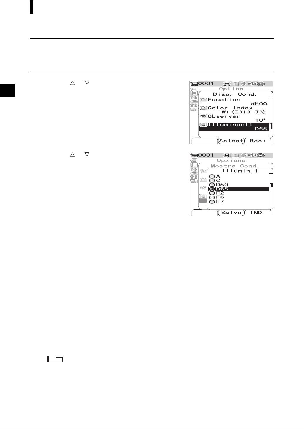
Illuminant 1
Select the illuminant used to measure colorimetric data.
[Setting Procedure] Start the procedure from the <Disp. Cond.> screen.
Use the or button of the cross key to
1
move the cursor to “Illuminant 1” and then
press the [SAVE/SEL] button.
The <Illuminant 1> screen is displayed.
Use the or button of the cross key to
2
move the cursor to the desired item.
Settings
❍A: Standard illuminant A
temperature: 2856K)
❍C: Illuminant C
(Daylight, The relative value of the spectral
distribution in the ultraviolet region is small;
Color temperature: 6774K)
:Illuminant D50 (Daylight, Color temperature:
❍D
50
5003K)
:Standard illuminant D65 (Daylight, Color
❍D
65
temperature: 6504K)
❍F2: Cool white (fluorescent lamp)
❍F6: Cool white (fluorescent lamp)
❍F7: Color rendering A daylight white (fluorescent
lamp)
❍F8: Color rendering AAA natural white (fluorescent
lamp)
❍F10: 3-band type natural white (fluorescent lamp)
❍F11: 3-band type cool white (fluorescent lamp)
❍F12: 3-band type warm white (fluorescent lamp)
(Incandescent lamp, Color
E-40
Press the [SAVE/SEL] button.
3
The selection is confirmed and the screen returns to the
<Disp. Cond.> screen.
Note
If you press the [TARGET] (Back) button without pressing the [SAVE/SEL] button, you return to the
<Disp. Cond.> screen without changing the setting.
Page 45

Condition Setting
Illuminant 2
Select the secondary illuminant used for MI (metamerism index) calculation, etc.
[Setting Procedure] Start the procedure from the <Disp. Cond.> screen.
Use the or button of the cross key to
1
move the cursor to “Illuminant 2” and then
press the [SAVE/SEL] button.
The <Illuminant 2> screen is displayed.
Use the or button of the cross key to
2
move the cursor to the desired item.
Settings
❍The setting values are the same as those for “Illuminant
1” and “None”.
Press the [SAVE/SEL] button.
3
The selection is confirmed and the screen returns to the
<Disp. Cond.> screen.
Note
If you press the [TARGET] (Back) button without pressing the [SAVE/SEL] button, you return to the
<Disp. Cond.> screen without changing the setting.
E-41
Page 46

Condition Setting
Setting the Measurement Conditions
To set measurement conditions, select “Meas. Cond.” from the <Option> screen.
You can select or specify the following four items as the measurement conditions:
• Mode: Select the specular component mode.
• Wait Time: Specify the delay between the press of the measuring button and the flash of the lamp.
• Auto Ave.: Specify the number of measurements for auto averaging.
• Manual Ave.: Specify the number of measurements for manual averaging.
[Setting Procedure]
Hold down the [MENU] button and press the
1
button of the cross key.
The <Option> screen is displayed.
Use the or button of the cross key to
2
move the cursor to “Meas. Cond.” and then
press the [SAVE/SEL] button.
The <Meas. Cond.> screen is displayed.
Note
When setting of “Cond” is “ON” (refer to page E-56),
“Disp. Cond” and “Meas. Cond” cannot be selected.
• The <Meas. Cond.> screen shows the current settings.
After you set the measurement conditions, press the [TARGET] (Back) button to
3
return to the <Option> screen.
E-42
Page 47

Condition Setting
Mode
Select the specular component mode.
[Setting Procedure] Start the procedure from the <Meas. Cond.> screen.
Use the or button of the cross key to
1
move the cursor to “Mode” and then press the
[SAVE/SEL] button.
The <Mode> screen is displayed.
Use the or button of the cross key to
2
move the cursor to the desired item.
Settings
❍SCI: Specular component included
❍SCE: Specular component excluded
❍SCI+SCE: Automatic SCI/SCE switching
Press the [SAVE/SEL] button.
3
The selection is confirmed and the screen returns to the
<Meas. Cond.> screen.
Note
If you press the [TARGET] (Back) button without pressing the [SAVE/SEL] button, you return to the
<Meas. Cond.> screen without changing the setting.
E-43
Page 48

Condition Setting
Wait Time
Specify the delay between the press of the measuring button and the flash of the lamp.
[Setting Procedure] Start the procedure from the <Meas. Cond.> screen.
Use the or button of the cross key to
1
move the cursor to “Wait Time” and then
press the [SAVE/SEL] button.
The <Wait Time> screen is displayed.
Use the or button of the cross key to
2
specify a value.
• Use the or button of the cross key to move the
cursor to the digit on the left or right.
Setting
❍Sec. [0.0 to 3.0]:
To eliminate the influence of instrument shake, provide a
period between the press of the measuring button and the
flash of the lamp for measurement in increments of 0.1
seconds. When 0.0 seconds is specified, measurement
starts immediately.
Press the [SAVE/SEL] button.
3
The selection is confirmed and the screen returns to the
<Meas. Cond.> screen.
Note
If you press the [TARGET] (Back) button without pressing the [SAVE/SEL] button, you return to the
<Meas. Cond.> screen without changing the setting.
E-44
Page 49

Condition Setting
Auto Averaging (Auto Ave.)
Specify the number of measurements for auto averaging.
[Setting Procedure] Start the procedure from the <Meas. Cond.> screen.
Use the or button of the cross key to
1
move the cursor to “Auto Ave.” and then
press the [SAVE/SEL] button.
The <Auto Ave.> screen is displayed.
Use the or button of the cross key to
2
specify a value.
• Use the or button of the cross key to move the
cursor to the digit on the left or right.
Setting
❍Times [1 to 10]:Specify the number of measurements,
from 1 to 10, to perform when using auto
averaging.
Press the [SAVE/SEL] button.
3
The selection is confirmed and the screen returns to the
<Meas. Cond.> screen.
Note
If you press the [TARGET] (Back) button without pressing the [SAVE/SEL] button, you return to the
<Meas. Cond.> screen without changing the setting.
E-45
Page 50
Condition Setting
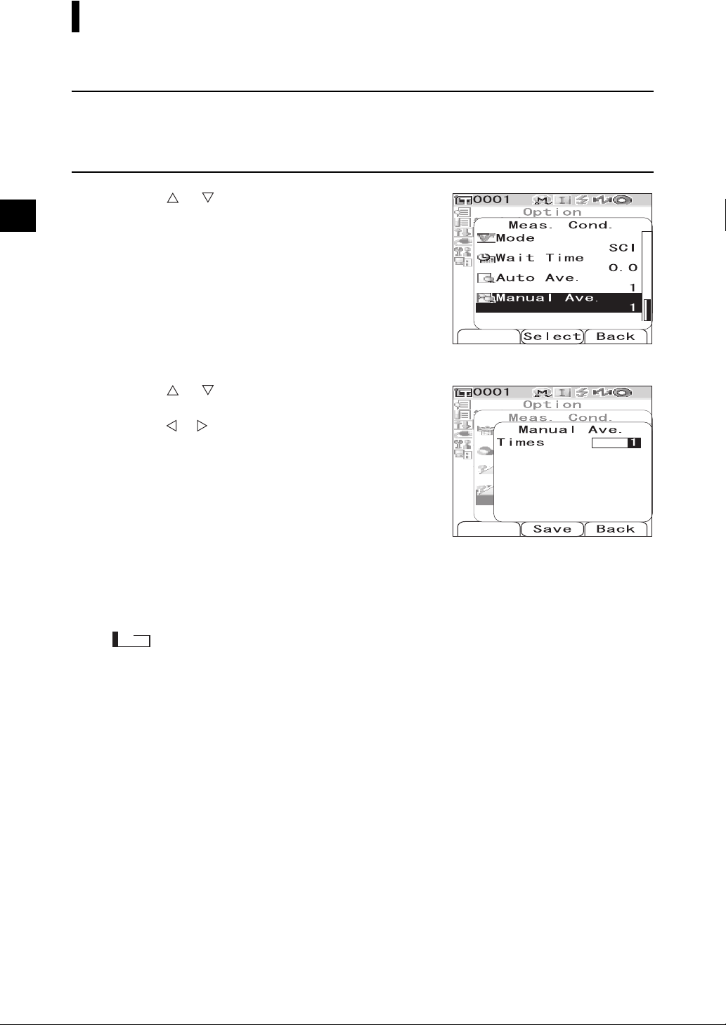
Manual Averaging (Manual Ave.)
Specify the number of measurements for manual averaging.
[Setting Procedure] Start the procedure from the <Meas. Cond.> screen.
Use the or button of the cross key to
1
move the cursor to “Manual Ave.” and then
press the [SAVE/SEL] button.
The <Manual Ave.> screen is displayed.
Use the or button of the cross key to
2
specify a value.
• Use the or button of the cross key to move the
cursor to the digit on the left or right.
Setting
❍Times [1 to 30]:Specify the number of measurements,
from 1 to 30, to perform when using
manual averaging.
Press the [SAVE/SEL] button.
3
The selection is confirmed and the screen returns to the
<Meas. Cond.> screen.
Note
If you press the [TARGET] (Back) button without pressing the [SAVE/SEL] button, you return to the
<Meas. Cond.> screen without changing the setting.
E-46
Page 51

Color Difference Target Color Data Operation
Setting a Target Color
To measure the color difference between two specimens, the color of one of the specimens must be set
as the target color. The CM-700d/600d can store up to 1,000 target colors.
When using the instrument alone, measure a target specimen by following the procedure below and set
the result as the target color.
M
emo
• Target colors are stored with setting numbers from 0001 to 1000 being assigned. Even when the data at some
midpoint is deleted, these setting numbers do not change. It is useful to group data by assigning numbers of
specific digits.
• The color difference tolerances used for pass/fail judgment are generally set for each target color. Consequently,
you can set the tolerances using the menu of a target color.
• To set more accurate target color data, use averaging to measure the target specimen. For details, refer to “Average
Measurement” on page E-88.
Note
• Be sure to perform white calibration before setting target colors.
• To ensure measurement accuracy, make sure to keep ambient conditions (temperature, etc.) constant.
[Setting Procedure]
Press the [TARGET] button.
1
The <Target> screen is displayed.
• Pressing the [SAVE/SEL] (List/Detail) button switches
the screen between detail display and list display.
Use the or button of the cross key to
2
move the cursor to a desired target color No.
Note
Unlike measured data, the numbers assigned to target
color data do not change automatically. When you
measure colors continuously to set target colors, you need
to move the cursor manually to set each data.
E-47
Page 52

Color Difference Target Color Data Operation
Place the specimen measuring port on the
3
specimen.
Make sure that (Ready to measure) is
4
displayed or Ready lamp is green, and then
press the measuring button.
The specimen is measured and the result is displayed on the
screen.
Note
If you selected a number to which target color data has
already been set, a message is displayed to confirm
overwriting.
Target name,
date & time, or
Pseudo color is
displayed.
To set more target colors, repeat steps 2 to 4.
5
Target Color Menu
The target color menu allows the following operations for target color data.
• Print: Print the target color data. This option can be selected only when a printer has been connected.
• Delete: Delete the target color data.
• Tolerance: Specify the tolerance (box tolerance) used for pass/fail judgment of measured data.
• Edit Name: Name the target color data.
• List: Specify the columns displayed for each target color No. in the list.
• Data Protect:
Disable the deletion of the target color data. When Data Protect is specified, “Delete” and “Delete All”
in the <Menu> screen cannot be selected.
• Delete All: Delete all the target color data except for protected data.
E-48
Page 53

Color Difference Target Color Data Operation
[Setting Procedure]
From the <Target> screen, press the [MENU]
1
button.
The <Menu> screen is displayed.
Use the or button of the cross key to
2
move the cursor to the item to select or
execute, and then press the [SAVE/SEL]
button.
The setting screen for the selected item is displayed.
For the setting procedure of each item, refer to the following
sections.
To return to the <Target> screen, press the [MENU] button while the <Menu>
3
screen is displayed.
Print
Print the target color data.
You need to establish a connection between the instrument and a Bluetooth printer in advance.
Note
• If proper connection is not established, you cannot select “Print” on the <Menu> screen.
• Even if the connection has been established, printing may fail for reasons such as, the printer is turned off
when printing is attempted.
[Setting Procedure]
Use the or button of the cross key to
1
move the cursor to “Print”.
Press the [SAVE/SEL] button. The <Print>
2
screen is displayed and the data is printed
from the connected printer.
• When the printing is complete, the screen returns to the
<Target> screen.
Start the procedure from the <Menu> screen of the <Target> screen.
E-49
Page 54

Color Difference Target Color Data Operation
Delete
Delete the target color data.
Note
When the data is protected, you cannot select “Delete” on the <Menu> screen.
[Setting Procedure]
Use the or button of the cross key to
1
move the cursor to “Delete” and then press
the [SAVE/SEL] button.
The <Delete> screen is displayed.
Use the button of the cross key to move the
2
cursor to “OK” and press the [SAVE/SEL]
button, and the data is deleted.
• When the deletion is complete, the screen returns to the
<Target> screen.
• When you place the cursor on “Cancel” and press the
[SAVE/SEL] button, the deletion is canceled and the
screen returns to the <Target> screen.
Start the procedure from the <Menu> screen of the <Target> screen.
Tolerance (Box Tolerance) Setting
Specify the tolerance (box tolerance) used for pass/fail judgment of measured data to each target color.
M
emo
• Before you set tolerance to each target color, the default tolerance selected for the measurement is set (factory setting:
No. 01). For details, refer to page E-59 “Setting the Default Color Difference Tolerance (Tolerance (Def.))”.
• With the optional Color Data Software “SpectraMagic™ NX”, you can set or use the color difference tolerance easily.
Note
The items which can be set as tolerance settings are the items for the currently selected default tolerance
registration number (initial setting at time of shipment: registration 01). Even if the display conditions (such as
color space or color difference equation, index, etc.) are changed, the tolerance setting items will not be changed.
If it is desired to change the tolerance setting items, after changing the display conditions, it is necessary to create
new tolerance settings in the Tolerance (Def.) screen.
[Setting Procedure]
Use the or button of the cross key to
1
move the cursor to “Tolerance” and then
press the [SAVE/SEL] button.
The <Tolerance> screen is displayed.
E-50
Start the procedure from the <Menu> screen of the <Target> screen.
Page 55

Use the or button of the cross key to move
2
the cursor to the desired item.
M
emo
• If / is displayed at the top of the screen, you can use the
or button of the cross key to change the combination of
the specular component mode and illuminant used for the
screen display.
• If / is displayed on the left side/end of the screen, you
can use the or button of the cross key to scroll the
display screen upward or downward.
Color Difference Target Color Data Operation
Press the [SAMPLE] (Edit) button and change the
3
setting.
• When you select an item which is currently checked and press
the [SAMPLE] (Edit) button, the check mark is cleared. When
you press the [SAMPLE] (Edit) button again, the cursor
moves to the setting value. Use the or button of the
cross key to change the value.
• When you select an item which is not currently checked and
press the [SAMPLE] (Edit) button, the cursor moves directly
to the setting value. Use the or button of the cross key
to change the value.
• To set each parameter l, c and h for CMC, ΔE*94 and ΔE00, place the cursor on the item and press the
[SAMPLE] (Edit) button, and the cursor moves to the value of the item. Press the or button of the
cross key to change the value.
M
emo
You can move the cursor between the digits of the value by pressing the or button of the cross key.
Settings
❍±0.0 to 20.0
* Settings of each parameter l, c and h for CMC, ΔΕ *94 and ΔE00 are 0.00 to 9.99.
• You need to press the [SAVE/SEL] (OK) button to confirm the change every time you change the setting
of an item.
E-51
Page 56

Color Difference Target Color Data Operation
When all items have been set, press the [SAVE/SEL] button.
4
The settings are confirmed and the screen returns to the <Target> screen.
Note
If you press the [TARGET] (Back) button without pressing the [SAVE/SEL] button, you return to the
<Target> screen without changing the settings.
Edit Name
Name the target color data.
[Setting Procedure]
Use the or button of the cross key to
1
move the cursor to “Edit Name” and then
press the [SAVE/SEL] button.
The <Edit Name> screen is displayed.
Use the or button of the cross key to
2
move the cursor, and use the
to change the letter.
• Use the button of the cross key to move the cursor
backward to correct letters.
• Pressing the [SAMPLE] (Clear) button clears all letters.
• Up to 16 characters can be used.
Start the procedure from the <Menu> screen of the <Target> screen.
or button
E-52
• The available letters are upper/lower-case alphabets, symbols, numbers (0 to 9), and a space.
Available symbols
!"#$%&'()*+
,-./:;<=>?@
[¥]^_‘{| }
When you have entered the name, press the [SAVE/SEL] button.
3
The screen returns to the <Target> screen.
Page 57

Color Difference Target Color Data Operation
Setting the List (List)
Specify the column displayed for each target color No. in the list.
[Setting Procedure]
Use the or button of the cross key to
1
move the cursor to “List” and then press the
[SAVE/SEL] button.
The <List> screen is displayed.
Use the or button of the cross key to
2
move the cursor to the desired item.
Settings
❍Name: Display the name specified with Edit
Name in the list.
❍Date&Time: Display the date and time of the
measurement in the list.
❍Pseudo Color:Display the pseudocolor in the list.
Press the [SAVE/SEL] button.
3
The settings are confirmed and the screen returns to the
<Target> screen.
Start the procedure from the <Menu> screen of the <Target> screen.
Note
If you press the [TARGET] (Back) button without pressing the [SAVE/SEL] button, you return to the
<Target> screen without changing the settings.
E-53
Page 58

Color Difference Target Color Data Operation
Data Protection
You can specify data protection so that the saved target color setting will not be deleted by accident.
When the data protection is specified, “Delete” and “Delete All” in the <Menu> screen cannot be
selected.
[Setting Procedure]
Use the or button of the cross key to
1
move the cursor to “Data Protect” and then
press the [SAVE/SEL] button.
The <Data Protect> screen is displayed.
Use the or button of the cross key to
2
move the cursor to the desired item.
Settings
❍ON: Protect the data.
❍OFF: Do not protect the data.
Press the [SAVE/SEL] button.
3
The settings are confirmed and the screen returns to the
<Target> screen.
Start the procedure from the <Menu> screen of the <Target> screen.
E-54
Note
If you press the [TARGET] (Back) button without pressing the [SAVE/SEL] button, you return to the
<Target> screen without changing the settings.
Page 59

Color Difference Target Color Data Operation
Delete All
Delete all the target color data which have been set.
Note
When the data is protected, you cannot select “Delete All” on the <Menu> screen.
[Setting Procedure]
Use the or button of the cross key to
1
move the cursor to “Delete All” and then
press the [SAVE/SEL] button.
The <Delete All> screen is displayed.
Use the button of the cross key to move the
2
cursor to “OK” and press the [SAVE/SEL]
button, and all of the data is deleted.
• When the deletion is complete, the screen returns to the
<Target> screen.
• When you place the cursor on “Cancel” and press the
[SAVE/SEL] button, the deletion is canceled and the
screen returns to the <Target> screen.
Start the procedure from the <Menu> screen of the <Target> screen.
E-55
Page 60

Registering Conditions (Cond)
The CM-700d/600d allows registration of up to 8 conditions (display and measurement conditions) in
advance.
You can display measurement results under desired conditions by switching registered conditions stored
as “Cond 01 to 08”.
Note
When “Cond” is ON (When one of Cond 01 to 08 is selected), you cannot set the display and measurement
conditions with the <Option> screen.
M
emo
To register conditions, select one of Cond 01 to 08 before setting details. When Cond is OFF (normal condition
setting), the settings are not saved.
[Setting Procedure]
Hold down the [MENU] button and press the
1
button of the cross key.
The <Option> screen is displayed.
E-56
Use the button of the cross key to move the
2
cursor to “Cond/OFF” and then press the
[SAVE/SEL] button.
The <Cond> screen is displayed.
Page 61

Use the or button of the cross key to
3
move the cursor to the desired registration
number (01 to 08), and then press the
[SAMPLE] (Edit) button.
A screen used to select the display conditions for the selected
registration number is displayed.
Use the or button of the cross key to
4
move the cursor to a desired item and then
press the [SAVE/SEL] button.
M
emo
For the setting procedure and details of the items, refer to
page E-32 “Condition Setting”.
Settings
❍Mode: Select the mode to process specular components.
❍Wait Time: Specify the delay between the press of the
measuring button and the flash of the lamp.
❍Auto Ave.: Specify the number of measurements for auto averaging.
❍Manual Ave.: Specify the number of measurements for manual averaging.
❍Disp. Type: Specify items to be displayed as measurement results.
❍Color Space: Select the color space to be used.
❍Equation: Select the color difference formula to be used.
❍Color Index: Select the index (WI, YI, etc.) to be used.
❍Observer: Select the observer angle from 2° or 10°.
❍Illuminant 1: Select the illuminant used to measure colorimetric data.
❍Illuminant 2: Select the secondary illuminant used for MI (metamerism index) calculation, etc.
Registering Conditions (Cond)
When the setting is complete, press the
5
[TARGET] (Back) button.
The screen returns to the <Cond> screen.
M
emo
To set two or more conditions, repeat steps 3 and 4.
Use the or button of the cross key to
6
move the cursor to the desired registration
number (OFF or 01 to 08), and then press the
[SAVE/SEL] button.
The selection is confirmed and the screen returns to the
<Option> screen.
E-57
Page 62

Registering Conditions (Cond)
Naming a Condition
You can name a condition for easier management.
[Setting Procedure]
From the <Cond> screen, press the [MENU]
1
button.
The <Menu> screen is displayed.
Make sure that “Edit Name” is selected, and
2
then press the [SAVE/SEL] button.
The <Edit Name> screen is displayed.
Use the or button of the cross key to
3
move the cursor, and use the or button
to change the letter.
• Use the button of the cross key to move the cursor
backward to correct letters.
• Pressing the [SAMPLE] (Clear) button clears all letters.
• Up to 16 characters can be used.
• The available letters are upper/lower-case alphabets,
symbols, numbers (0 to 9), and a space.
Available symbols
!"#$%&' ()*+
,-./:;<=>?@
[¥]^_‘{|}
When you finish entering letters, press the
4
[SAVE/SEL] button.
The screen returns to the <Cond> screen.
E-58
Page 63

Setting the Default Color Difference Tolerance (Tolerance (Def.))
With the CM-700d/600d, you can preset and save tolerances which do not depend on the target color data
as default values. During measurement, just selecting the tolerance No. allows automatic judgment using
the target colors and tolerances.
M
emo
• If tolerances for each target color have not been set, the tolerance setting for the registration number selected
during measurement (initial value: 01) is used as the tolerance setting for each target color.
• Up to 8 default tolerance settings can be specified to registration numbers 01 to 08. Tolerances have been factoryset to registration number 01 only. You need to set tolerances for registration numbers 02 to 08 as necessary.
• With the optional Color Data Software “SpectraMagic™ NX”, you can set or use the color difference tolerance
easily.
Note
Registration 01 for tolerance settings is set as the initial setting at the time of shipment from the factory, and
contains default settings for tolerance items. Even if the display conditions (such as color space or color
difference equation, index, etc.) are changed, the tolerance setting items will not be automatically changed.
If it is desired to set tolerance values according to the currently set display conditions, either delete the currently
set tolerance settings and then create new tolerance settings, or create new tolerance settings for a registration
number for which tolerances have not yet been set and select that registration number.
[Setting Procedure]
Hold down the [MENU] button and press the
1
button of the cross key.
The <Option> screen is displayed.
Use the or button of the cross key to
2
move the cursor to “Tolerance(Def.)” and
then press the [SAVE/SEL] button.
The <Tolerance(Def.)> screen is displayed.
E-59
Page 64

Setting the Default Color Difference Tolerance (Tolerance (Def.))
Use the or button of the cross key to
3
move the cursor to the desired registration
number (01 to 08).
Press the [SAMPLE] (Edit) button.
4
A screen used to set tolerances for the selected registration
number is displayed.
M
emo
• If registration number 01 (initial setting) is selected, or if
you select a number with which tolerances have already
been registered, a screen used to change the current
tolerance setting is displayed.
• If you select a registration number for which no tolerance
has been set, a blank screen is displayed. To set tolerances,
press the [MENU] button to display the <MENU> screen.
Move the cursor to “Create” and press the [SAVE/SEL]
button, and the tolerance setting screen is displayed.
Use the or button of the cross key to
5
move the cursor to the desired item.
M
emo
• If / is displayed at the top of the screen, you can use
the or button of the cross key to change the
combination of the specular component mode and
illuminant used for the screen display.
• If / is displayed on the left side/end of the screen, you
can use the or button of the cross key to scroll the
display screen upward or downward.
E-60
Page 65

Setting the Default Color Difference Tolerance (Tolerance (Def.))
Press the [SAMPLE] (Edit) button and change
6
the setting.
• When you select an item which is currently checked and
press the [SAMPLE] (Edit) button, the check mark is
cleared. When you press the [SAMPLE] (Edit) button
again, the cursor moves to the setting value. Use the or
button of the cross key to change the value.
• When you select an item which is not currently checked
and press the [SAMPLE] (Edit) button, the cursor moves
directly to the setting value. Use or button of the cross key to change the value.
• To set each parameter l, c and h for CMC, ΔE*94 and ΔE00, place the cursor on the item and press the
[SAMPLE] (Edit) button, and the cursor moves to the value of the item. Press the or button of the
cross key to change the value.
M
emo
You can move the cursor between the digits of the value by pressing the or button of the cross key.
Settings
❍±0.0 to 20.0
* Settings of each parameter l, c and h for CMC, ΔΕ *94 and ΔE00 are 0.00 to 9.99.
• You need to press the [SAVE/SEL] (OK) button to confirm the change every time you change the setting
of an item.
When all items have been set, press the
7
[SAVE/SEL] button.
The settings are confirmed and the screen returns to the
<Tolerance(Def.)> screen.
M
emo
To set two or more default tolerances, repeat steps 3 through
7.
Note
If you press the [TARGET] (Back) button without pressing
the [SAVE/SEL] button, you return to the <Tolerance(Def.)> screen without changing the settings.
E-61
Page 66

Setting the Default Color Difference Tolerance (Tolerance (Def.))
Selecting Color Difference Tolerances
You can set color difference tolerances to individual target colors when they are measured. You can also
select one of the predefined tolerances (default tolerances) and use it for judgment.
M
emo
A default tolerance setting can be registered with each registration number from 01 to 08. Before shipment,
registration number 01 has been selected. Its tolerance setting is used as a default tolerance setting, which can be set
to each target color.
Note
When you select a registration number for which no tolerance has been set, the tolerance setting for each target
color is also blank.
[Setting Procedure]
Hold down the [MENU] button and press the
1
button of the cross key.
The <Option> screen is displayed.
Use the or button of the cross key to
2
move the cursor to “Tolerance(Def.)” and
then press the [SAVE/SEL] button.
The <Tolerance(Def.)> screen is displayed.
Use the or button of the cross key to
3
move the cursor to the desired registration
number.
M
emo
If you press the [SAMPLE] (Edit) button here, you can
check the tolerance setting of the registration number. After
checking the setting, press the [SAVE/SEL] (OK) button to
return to the <Tolerance(Def.)> screen.
Press the [SAVE/SEL] button.
4
The selection is confirmed and the screen returns to the <Option> screen.
E-62
Page 67

Setting the Default Color Difference Tolerance (Tolerance (Def.))
Deleting the Default Color Difference Tolerance Setting
Delete the setting of the default tolerance of the selected registration number.
[Setting Procedure] Start the procedure from the <Tolerance(Def.)> screen.
Use the or button of the cross key to
1
move the cursor to the registration number
for which you want to delete the setting, and
then press the [SAMPLE] (Edit) button.
A screen used to set tolerances for the selected registration
number is displayed.
Press the [MENU] button.
2
The <Menu> screen is displayed.
Use the or button of the cross key to
3
move the cursor to “Clear”, and then press
the [SAVE/SEL] button. The setting of the
selected registration number is deleted.
M
emo
After the setting is deleted, the screen for the registration
number is blank.
E-63
Page 68
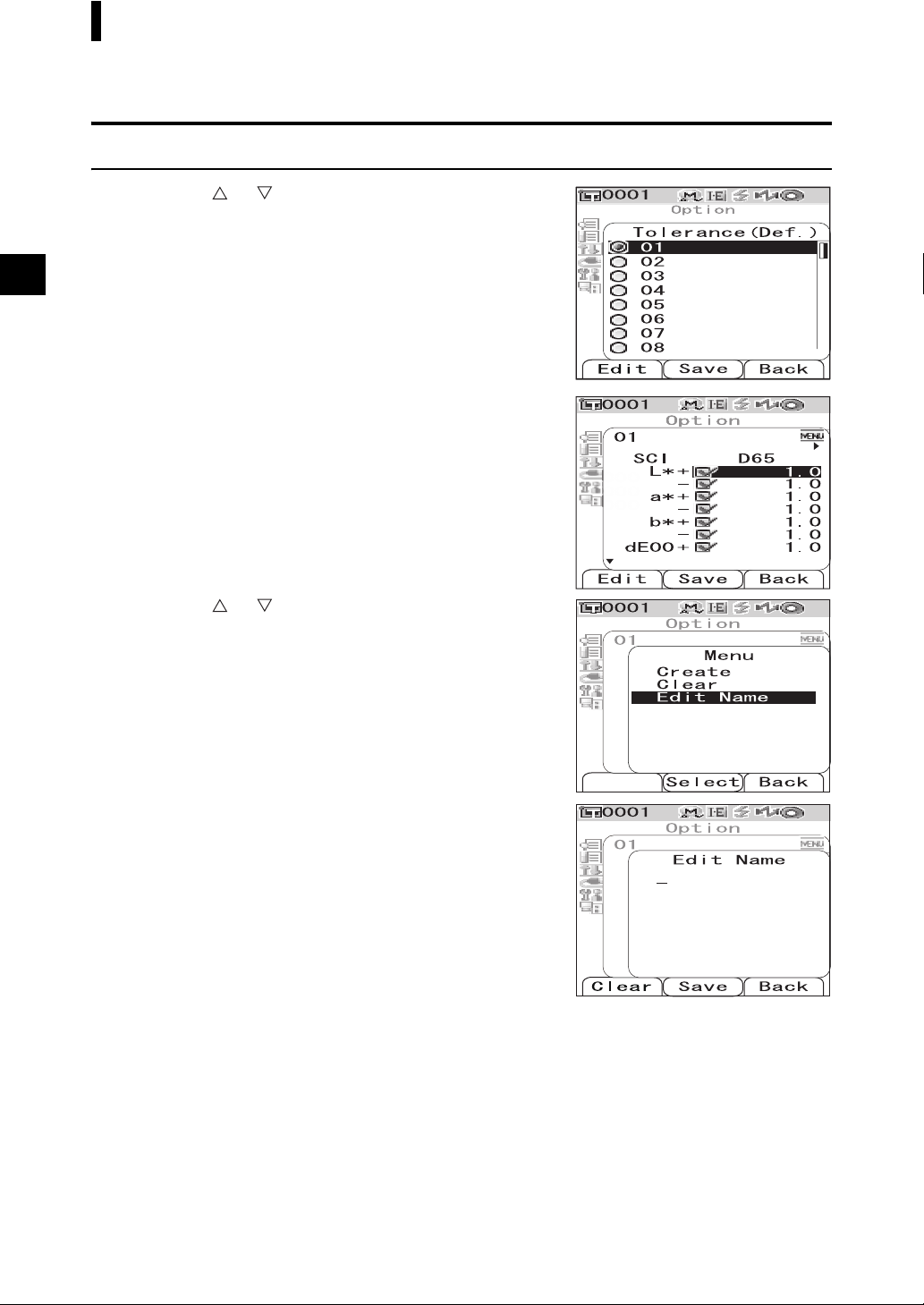
Setting the Default Color Difference Tolerance (Tolerance (Def.))
Naming the Color Difference Tolerance Setting
[Setting Procedure] Start the procedure from the <Tolerance(Def.)> screen.
Use the or button of the cross key to
1
move the cursor to the registration number
for which you want to edit the name, and then
press the [SAMPLE] (Edit) button.
A screen used to set tolerances for the selected registration
number is displayed.
Press the [MENU] button.
2
The <Menu> screen is displayed.
Use the or button of the cross key to
3
move the cursor to “Edit Name” and then
press the [SAVE/SEL] button.
The <Edit Name> screen is displayed.
E-64
Page 69
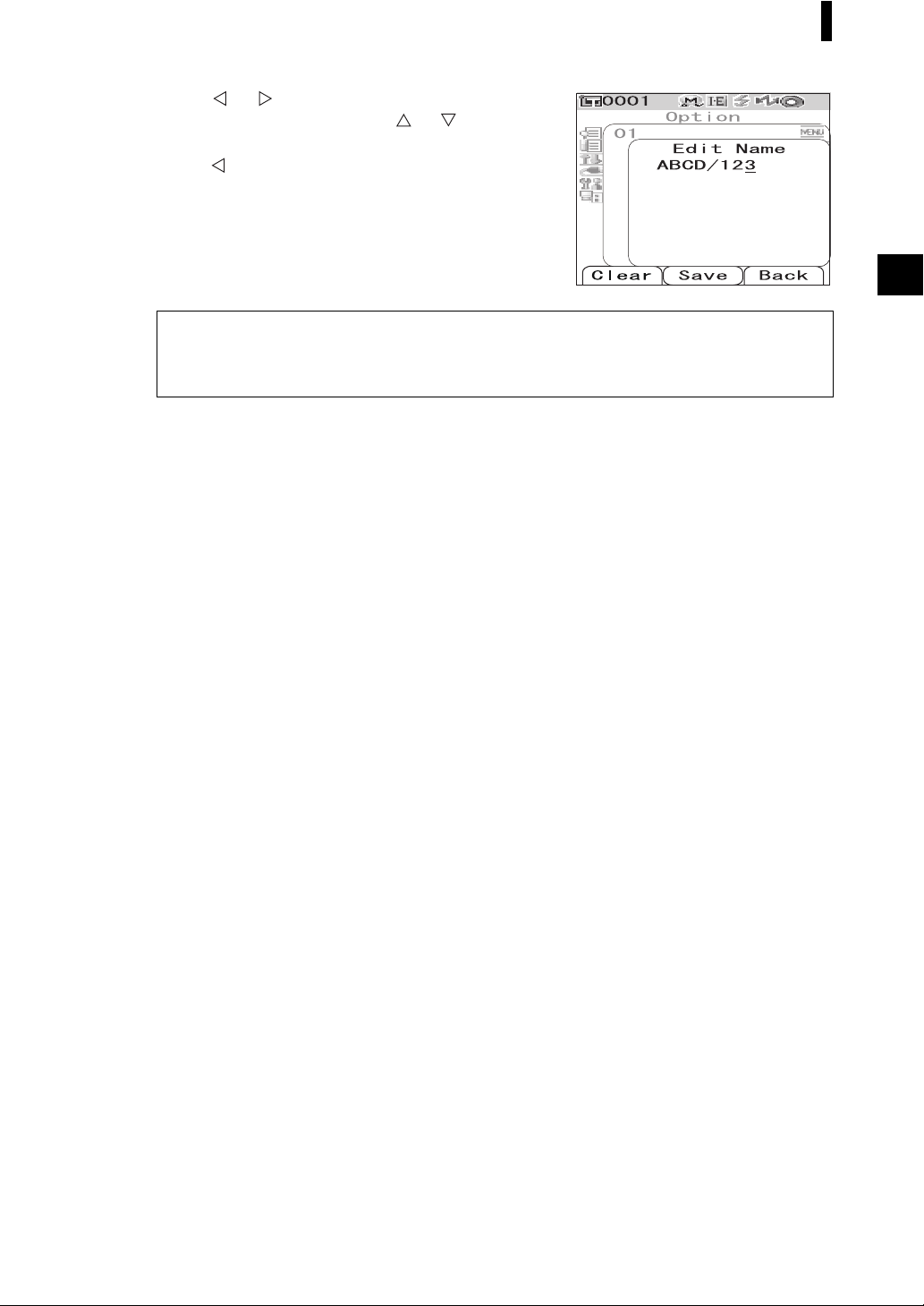
Setting the Default Color Difference Tolerance (Tolerance (Def.))
Use the or button of the cross key to
4
move the cursor, and use the
to change the letter.
• Use the button of the cross key to move the cursor
backward to correct letters.
• Pressing the [SAMPLE] (Clear) button clears all letters.
• Up to 16 characters can be used.
• The available letters are upper/lower-case alphabets,
symbols, numbers (0 to 9), and a space.
Available symbols
!"#$%&'()*+
,-./:;<=>?@
[¥]^_‘{|}
When you finish entering letters, press the [SAVE/SEL] button.
5
The screen returns to a screen used to set tolerances for the selected registration number.
or button
E-65
Page 70

Other Settings
Setting the Display Language
The display language can be changed from the factory-set language. Available languages are: English,
Japanese, German, French, Spanish, Italian, and Chinese.
M
emo
The language is factory-set to “English”.
Note
When the backup battery of the instrument has gone dead or the instrument is initialized (refer to page E-72), the
display language is reset to English regardless of the set language.
[Setting Procedure]
Hold down the [MENU] button and turn ON the
1
instrument.
The <Language> screen is displayed.
SAMPLE TARGET
SAVE
SEL
CAL
E-66
Use the or button of the cross key to
2
move the cursor to the desired language.
* The figure shows an example when German (Deutsch) is
selected.
Page 71

Other Settings
Press the [SAVE/SEL] button.
3
The <Calibration> screen is displayed in the selected
language.
* The figure shows an example when German (Deutsch) is
selected.
Setting the Date and Time
The CM-700d/600d has a built-in clock to record the date and time of measurement. Since the date and
time have been set at the factory, you do not need to change them under normal conditions. If necessary,
you can change the date and time settings.
[Setting Procedure]
Hold down the [MENU] button and press the
1
button of the cross key.
The <Option> screen is displayed.
Use the button of the cross key to move the
2
cursor to “Settings” and then press the
[SAVE/SEL] button.
The <Settings> screen is displayed.
Use the button of the cross key to move the
3
cursor to “Date&Time” and then press the
[SAVE/SEL] button.
The <Date&Time> screen is displayed.
E-67
Page 72

Other Settings
If you want to change the date format, move
4
the cursor to “Format” and then press the
[SAVE/SEL] button.
The <Format> screen is displayed.
M
emo
This step is unnecessary if you do not change the date
format. Go to step 6 on the next page.
Use the or button of the cross key to
5
move the cursor to the desired format and
then press the [SAVE/SEL] button.
The screen returns to the <Date&Time> screen.
Settings
❍YYYY/MM/DD: Display the date in the format of year/
month/day.
❍MM/DD/YYYY: Display the date in the format of
month/day/year.
Use the or button of the cross key to
6
move the cursor to “Setting” and then press
the [SAVE/SEL] button.
The <Setting> screen is displayed.
E-68
Use the , , or button of the cross key
7
to move the cursor to the block of the item
which you want to change.
M
emo
The date consists of blocks of the year, month and day, and
the time consists of blocks of the hour, minute and second.
To change the values, you need to change the blocks
individually.
• Pressing the or button of the cross key moves the
cursor between the date setting line and the time setting
line.
• Pressing the or button of the cross key moves the
cursor among the blocks on either the date setting line or
the time setting line.
Page 73

Other Settings
Press the [SAMPLE] (Edit) button.
8
The cursor moves to the position where the setting can be changed.
• Use the or button of the cross key to change the values.
Note
Every time you change the value of a block, you need to press the [SAVE/SEL] (OK) button to confirm
the change. You cannot move to the next block unless you confirm the change of the current block.
Settings
❍Year: 2000 to 2050
❍Month: 1 to 12
❍Day: 1 to 28, 29, 30 and 31 (varies with the selected month/year)
❍Hour: 0 to 23
❍Minute: 0 to 59
❍Second: 0 to 59
When all of the necessary items have been changed, press the [SAVE/SEL] button.
9
The settings are confirmed, and the screen returns to the <Date&Time> screen.
• Press the [TARGET] (Back) button twice to return to the <Option> screen.
E-69
Page 74

Other Settings
Setting the Power Save Mode
The CM-700d/600d features a power save function which turns off the screen display and stops the power
supply to the flash circuit after no operation was made for a specified period of time. The period before the
activation of the power save function can be set to 0 (OFF) or within the range from 1 to 60 minutes.
Note
The power save function is factory-set to OFF.
[Setting Procedure]
Hold down the [MENU] button and press the
1
button of the cross key.
The <Option> screen is displayed.
Use the button of the cross key to move the
2
cursor to “Settings” and then press the
[SAVE/SEL] button.
The <Settings> screen is displayed.
Use the button of the cross key to move the
3
cursor to “Low Power” and then press the
[SAVE/SEL] button.
The <Low Power> screen is displayed.
E-70
Page 75

Use the or button of the cross key to
4
change the time before the power save mode
is activated by specifying the number of
minutes.
M
emo
Holding down the or button of the cross key changes
the value continuously.
• When you finish changing the setting, press the
[TARGET] (Back) button to return to the <Settings>
screen of the Option menu.
Settings
❍0: Disable the power save mode.
❍1 to 60: 1 to 60 minutes
When the change is complete, press the [SAVE/SEL] button.
5
The setting is confirmed and the screen returns to the <Settings> screen.
Note
If you press the [TARGET] (Back) button without pressing the [SAVE/SEL] button, you return to the
<Settings> screen without changing the setting.
Other Settings
E-71
Page 76

Other Settings
Initialization
Reset the settings of the instrument to the initial status.
Note
• Do not initialize the instrument unless necessary.
• The measured data, target color data, tolerances set to each target color and default tolerance settings will be
protected and not be deleted by initialization.
• After the initialization, the display language is reset to English. Change the language if necessary.
M
emo
The measured data and target color data which you saved will be stored even after initialization.
For details of the initial setting values, refer to page E-116 “Initial Settings”.
[Setting Procedure]
Turn ON the instrument while holding down
1
the [TARGET] and [SAMPLE] buttons simultaneously.
The <Initialize> screen is displayed.
SAMPLE TARGET
SAVE
SEL
CAL
Use the or button of the cross key to
2
move the cursor to “OK” and then press the
[SAVE/SEL] button.
Initialization will be performed.
M
emo
When you place the cursor on “Cancel” on the <Initialize> screen and press the [SAVE/SEL] button, the
initialization is canceled and the <Calibration> screen is displayed.
E-72
Page 77

Chapter 3
Measurement
E-73
Page 78
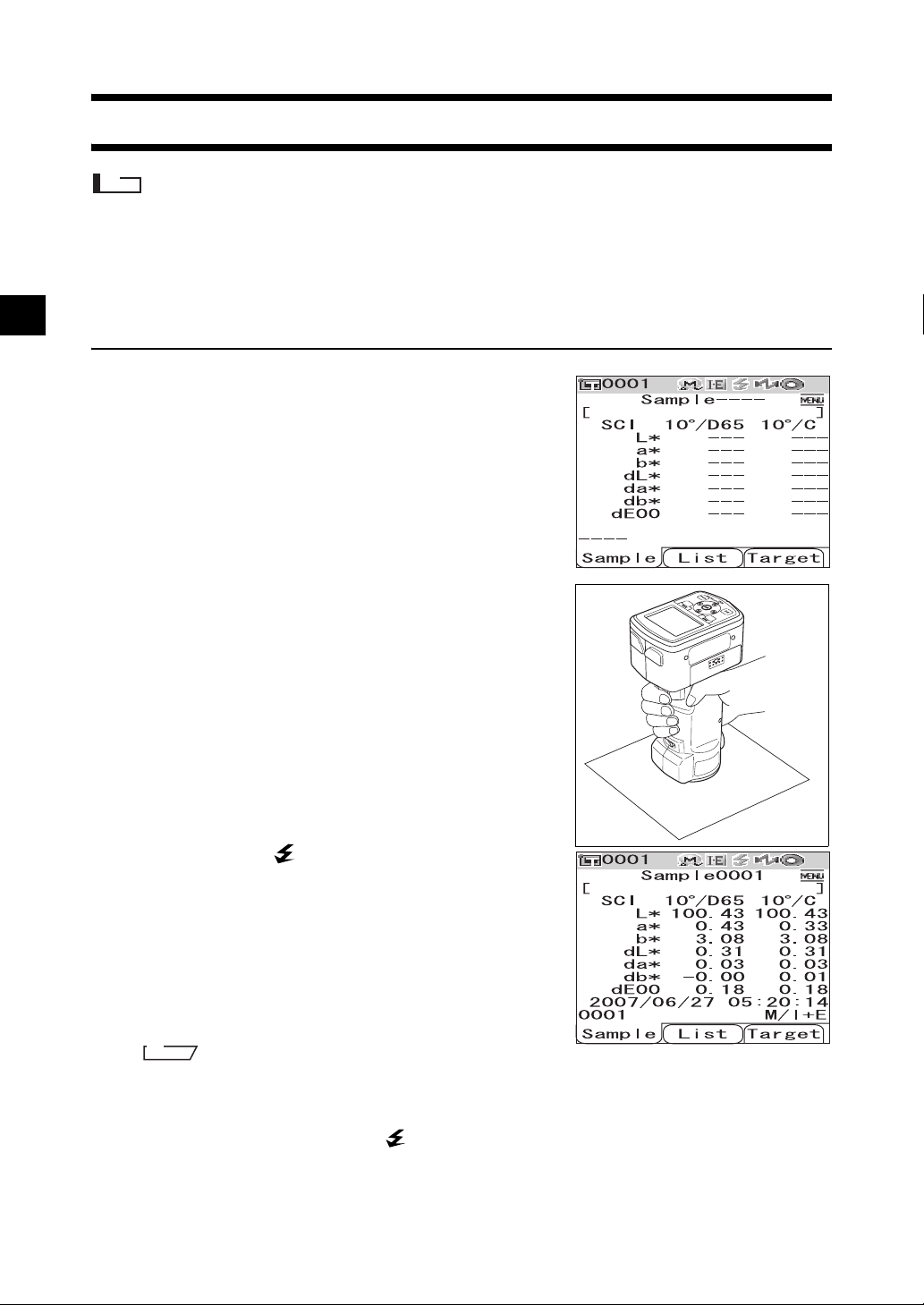
Measurement
Note
• Prior to start of measurement, be sure to perform white calibration. For details, refer to page E-29 “White
Calibration”.
• To display color difference, it is necessary to set target colors before measurement.
• For accurate measurement, make sure to keep measurement conditions (ambient temperature etc.) constant.
[Setting Procedure]
Press the [SAMPLE] button.
1
The <Sample> screen is displayed.
Place the specimen measuring port on the
2
specimen.
E-74
Make sure that (Ready to measure) is
3
displayed or Ready lamp is green, and then
press the measuring button.
The specimen is measured and the result is displayed on the
screen.
• The sample data Nos. are automatically assigned
sequentially in the order of measurements.
M
emo
• When the number of measured data sets stored in the memory reaches 4000, the number assigned to the
subsequent measured data will always be No. 4000, and the oldest data will be deleted one by one.
• When the screen is turned OFF by the power save function, press any of the measuring or control buttons
to turn ON the screen, confirm that (Ready to measure) is displayed or Ready lamp is green, and then
press the measuring button.
• When I + E (SCI + SCE) is specified as the specular component mode (refer to page E-43 “Mode”), clicks
caused by opening and closing the optical trap may be heard during the measurement.
Page 79
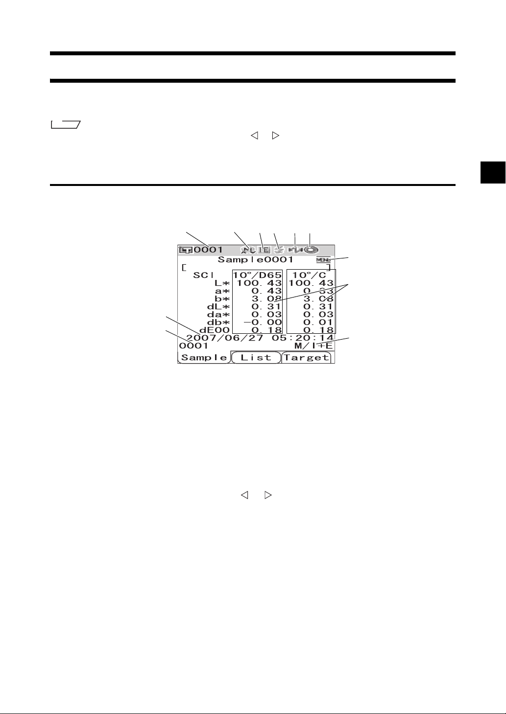
Displaying the Measurement Results
At the end of measurement, the measurement results will be displayed on the LCD according to the
specified measurement conditions. Typical measurement result screens are shown below.
M
emo
You can switch the measurement result screens with the or button of the cross key. For details of the screen
switching, refer to page E-78 “Switching the Display Contents of the Measurement Results”.
Measured Data
The figure below shows a sample screen where “Abs. & Diff.” is selected for “Disp. Type” of the display
condition.
1 23456
11
7
8
9
1 Data No. of the currently selected target color data.
2 Current lens position (M: MAV, S: SAV)
• With the CM-600d, only “MAV” can be used.
3 Current specular component mode (I: SCI, E: SCE, I+E: SCI + SCE)
4 Ready to measure
5 Bluetooth mode is ON.
6 White calibration completed
7 Measured data (Can be switched with the or button of the cross key.)
• When both illuminants 1 and 2 are set, the measurement results for both illuminants are displayed.
The results of the measurement using illuminant 1 are displayed on the left, and the results using
illuminant 2 are displayed on the right.
• The measured data which failed the pass/fail judgment based on the color difference tolerance will
be highlighted in red.
8 Date and time of the measurement
9 Data No. of the target color data used for the measurement
10 Lens position and specular component mode used for the measurement
10
11 Indicates that pressing the [MENU] button will display the <Menu> screen.
E-75
Page 80

Displaying the Measurement Results
Pass/Fail Judgment
The following screens are displayed when “Judge” has been selected for “Disp. Type” of the current
display conditions.
• When the result was “Pass”
The background is shown in green.
• When the result was “Fail”
The background is shown in red.
Color Difference Graph
The following screen is displayed when “Graph Diff.” has been selected for “Disp. Type” of the current
display conditions.
The target color will be plotted on the graph.
Note
• If a target color has not been set for the selected data No., no point is displayed on the graph.
E-76
Page 81
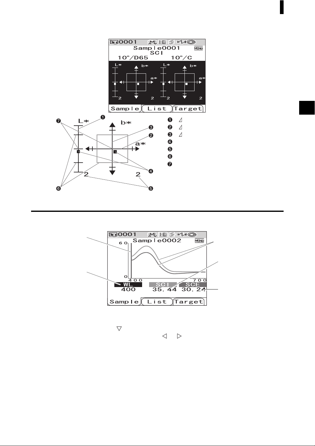
• Color difference graph
Displaying the Measurement Results
L* axis (color difference graph)
a * axis (color difference graph)
b* axis (color difference graph)
Measuring point
Scales for the axes
Specified box tolerances
Position of target color
Spectral Reflectance Graph
The following screen is displayed when “Graph Spec.” has been selected for “Disp. Type” of the current
display conditions.
1
2
1 Position of the currently selected wavelength
2 WL: Select the wavelength used in the spectral reflectance graph.
To select wavelength, use the button of the cross key to move the cursor to the value at the
bottom of the screen (unit: nm), then press the or button of the cross key.
3 SCI: Spectral reflectance in SCI (Specular Component Included) mode
* When the specular component mode is SCE, no value is displayed.
4 SCE: Spectral reflectance in SCE (Specular Component Excluded) mode
* When the specular component mode is SCI, no value is displayed.
5
3
4
5 Spectral graph: The graph shows the spectral reflectance measured in SCI mode with a blue
line, and it shows the reflectance measured in SCE mode with a green line.
E-77
Page 82

Displaying the Measurement Results
Switching the Display Contents of the Measurement Results
The contents of the measurement result display can be changed by pressing the or button of the cross
key on the <Sample> screen. The contents will vary depending on the display type setting.
M
emo
The color difference is displayed only when target data has been set.
1 2 3 4 5 6 7 8 9 10
Display
type
Absolute
value
Color
difference
Color
difference
and
Absolute
value
Judgment
Spectral
graph
Color
difference
graph
Pseudo
color
Color
assessment
SCI SCE SCI SCE SCI
Absolute
value/
Illuminant
setting
Illuminants
1 and 2
Illuminant 1
only
Illuminants
1 and 2
Illuminant 1
only
Illuminants
1 and 2
Illuminant 1
only
Illuminants
1 and 2
Illuminant 1
only
Illuminants
1 and 2
Illuminant 1
only
Illuminants
1 and 2
Illuminant 1
only
Illuminants
1 and 2
Illuminant 1
only
Illuminants
1 and 2
Illuminant 1
only
Illuminant 1
Absolute
Mode
value
I+E
SCI
SCE --- --I+E
SCI
SCE --I+E
SCI
SCE --- --I+E
SCI
SCE --- --I+E
SCI
SCE
I+E
SCI
SCE
I+E
SCI
SCE
I+E
SCI
SCE
I+E
SCI
SCE
I+E
SCI
SCE
I+E
SCI
SCE
I+E
SCI
SCE
I+E
SCI
SCE
I+E
SCI
SCE
I+E
SCI
SCE
I+E
SCI
SCE
{
{
Absolute
value/
Illuminant 2
Absolute
MI
value
{{{{
{{
---
✕
---
✕
---
✕
Absolute
value/
Illuminant 1
Absolute
MI
value
✕
✕
✕
{
---
{
Absolute
value/
Illuminant 2
Absolute
MI
value
--- ---
{{
---
✕
---
✕
---
✕
Color
difference +
Equation
Illumi-
MI
nant 1
✕
✕
✕
{{{{
{{
{
{
Color
difference +
Equation
Illumi-
Illumi-
nant 2
nant 1
--- ---
{{
---
{
--- --- ---
{
Illuminant 2
---
---
Color
difference +
Absolute
value
Illuminant 1
{
{
Color index
Illumi-
Color index
nant 2
{{
{{
--- ---
---
{
---
--- ---
{
MI
✕
✕
✕
E-78
Page 83

Displaying the Measurement Results
Table legend
{ : The screen is displayed.
--- : The screen is displayed, but the result “---” will be displayed; or the
measurement result will not be displayed.
✕ : The screen is displayed, but the item will not be displayed.
Shadowed : The screen is not displayed.
11 12 13 14 15 16 17 18 19 20
Color
difference +
Absolute
value
Illumi-
Illumi-
nant 1
nant 2
SCE
Color index
Color
index
MI
SCI/SCE
Judgment
SCI/SCE SCI SCE SCI SCE SCI SCE
Spectral
graph
SCI SCE
Color
difference
graph
Illuminant 1
Illuminant 2
Color
difference
graph
Illuminant 1
Pseudo color Pseudo color
Illumi-
Illuminant 1
Illuminant 2
nant 2
Illuminant 1
Illuminant 2
Color
assessment
Illuminant 1
Illuminant 2
Color
assessment
Illuminant 1
Illuminant 2
{{
--- ---
{{
---
{
--- ---
{
{
---
{
✕
✕
✕
{
{
{
{
{
{
{
---
{
---
{
{
---
{
---
{
{{
{
---
---
{
--- ---
{
---
---
{
---
{
---
{
{{
{
✕
✕
{
✕✕
{
✕
✕
{
✕
{
✕
{
{{
{
---
---
{
--- ---
{
---
---
{
---
{
---
{
E-79
Page 84

Displaying the Measurement Results
Display order of the measurement result screens (when all the items are selected for “Disp. Type”.)
1 Absolute value/SCI/
Illuminant 1
2 Absolute value/SCI/
Illuminant 2
3 Absolute value/SCE/
Illuminant 1
4 Absolute value/SCE/
Illuminant 2
5 Color difference/SCI/
Illuminant 1
6 Color difference/SCI/
Illuminant 2
11 Color difference &
Absolute value/SCE/
Illuminants 1 and 2
12 Color index/SCE/
Illuminants 1 and 2
13 Judgment
14 Spectral graph
15 Color difference graph/
SCI
16 Color difference graph/
SCE
7 Color difference/SCE/
Illuminant 1
8 Color difference/SCE/
Illuminant 2
9 Color difference &
Absolute value/SCI/
Illuminants 1 and 2
10 Color index/SCI/
Illuminants 1 and 2
Continues to 11
17 Pseudo color/SCI
18 Pseudo color/SCE
19 Color assessment/SCI
20 Color assessment/SCE
Returns to 1
E-80
Page 85

Measured Data Operation
The following operations are available for the measured data.
• Print: Print the measured data.
• Delete: Delete the measured data.
• Edit Name: Name the measured data.
• List: Specify the columns displayed for each sample data No. in the list.
• Auto Target: Automatically select a target color with the smallest color difference for measurement.
• Delete All: Delete all the measured data.
[Operating Procedure]
From the <Sample> screen, press the [MENU]
1
button.
The <Menu> screen is displayed.
Use the or button of the cross key to move
2
the cursor to an item to select or execute, and
then press the [SAVE/SEL] button.
The setting screen for the selected item is displayed.
For the operating procedure of each item, refer to the
following sections.
To return to the <Sample> screen, press the
3
[MENU] button while the <Menu> screen is
displayed.
E-81
Page 86

Measured Data Operation
Print the measured data.
You need to establish a connection between the instrument and a Bluetooth printer in advance.
Note
If proper connection is not established, you cannot select “Print” on the <Menu> screen.
[Operating Procedure]
Use the or button of the cross key to move
1
the cursor to “Print”.
Press the [SAVE/SEL] button. The <Print>
2
screen is displayed and the data is printed
from the connected printer.
When the printing is complete, the screen returns to the
<Sample> screen.
Start the procedure from the <Menu> screen of the <Sample> screen.
Delete
Delete the measured data.
[Operating Procedure]
Use the or button of the cross key to move
1
the cursor to “Delete” and then press the
[SAVE/SEL] button.
The <Delete> screen is displayed.
E-82
Start the procedure from the <Menu> screen of the <Sample> screen.
Page 87

Use the button of the cross key to move the
2
cursor to “OK” and press the [SAVE/SEL]
button. Data will be deleted.
M
emo
When data is deleted, the subsequent sample data Nos. will be
reassigned, reducing them by one.
• When the deletion is complete, the screen returns to the
<Menu> screen.
• When you place the cursor on “Cancel” and press the
[SAVE/SEL] button, the deletion is canceled and the screen
returns to the <Menu> screen.
Edit Name
Name the measured data.
Measured Data Operation
[Setting Procedure]
Use the or button of the cross key to move
1
the cursor to “Edit Name” and then press the
[SAVE/SEL] button.
The <Edit Name> screen is displayed.
M
emo
The initial value for the name is “No Name”.
Use the or button of the cross key to move
2
the cursor, and use the or button to
change the letter.
• Use the button of the cross key to move the cursor
backward to correct letters.
• Pressing the [SAMPLE] (Clear) button clears all letters.
• Up to 16 characters can be used.
• The available letters are upper/lower-case alphabets, symbols, numbers (0 to 9), and a space.
Available symbols
!"#$%&' ()*+
,-./:;<=>?@
[¥]^_‘{| }
Start the procedure from the <Menu> screen of the <Sample> screen.
When you finish entering letters, press the [SAVE/SEL] button.
3
The name is confirmed, and the screen returns to the <Menu> screen.
Note
If you press the [TARGET] (Back) button without pressing the [SAVE/SEL] button, you return to the
sample data screen without changing the name.
E-83
Page 88

Measured Data Operation
Setting the List (List)
When the <Sample> screen is displayed, pressing the [SAVE/SEL] button switches the screen between
the list display and detail display. Specify the columns displayed for each sample data No. in the list.
[Setting Procedure]
Use the or button of the cross key to move
1
the cursor to “List” and then press the [SAVE/
SEL] button.
The <List> screen is displayed.
Use the or button of the cross key to move
2
the cursor to the desired item.
Settings
❍Name: Display the name specified with Edit Name in the
list.
❍Date&Time: Display the date and time of the
measurement in the list.
❍Pseudo Color: Display the pseudocolor in the list.
Press the [SAVE/SEL] button.
3
The selection is confirmed and the screen returns to the <Menu> screen.
Start the procedure from the <Menu> screen of the <Sample> screen.
Note
If you press the [TARGET] (Back) button without pressing the [SAVE/SEL] button, you return to the
sample data screen without changing the setting.
Auto Target
Automatically select the target color with the smallest color difference (ΔE*ab) for measurement.
M
emo
The target color will be selected from those with the same specular component mode setting as the measurement.
For example, when the specular component mode “I + E” is used for the measurement, the target color is selected
from those for which “I + E” has been set.
Note
• Do not use this function if you want to check the color difference from a specific target color.
• This setting will not be applied to the measured data obtained before this function is set to ON.
E-84
Page 89

Measured Data Operation
[Setting Procedure]
Use the or button of the cross key to move
1
the cursor to “Auto Target” and then press the
[SAVE/SEL] button.
The <Auto Target> screen is displayed.
Use the or button of the cross key to move
2
the cursor to “ON” or “OFF”.
Settings
❍ON: Use the Auto Target function for measurement.
❍OFF: Do not use the Auto Target function.
Press the [SAVE/SEL] button.
3
The selection is confirmed and the screen returns to the <Menu> screen.
Start the procedure from the <Menu> screen of the <Sample> screen.
Note
If you press the [TARGET] (Back) button without pressing the [SAVE/SEL] button, you return to the
sample data screen without changing the setting.
Delete All
Delete all the measured data.
[
Operating Procedure]
Use the or button of the cross key to move
1
the cursor to “Delete All” and then press the
[SAVE/SEL] button.
The <Delete All> screen is displayed.
Start the procedure from the <Menu> screen of the <Sample> screen.
E-85
Page 90

Measured Data Operation
Use the button of the cross key to move the
2
cursor to “OK” and press the [SAVE/SEL]
button, and the data is deleted.
• When the deletion is complete, the screen returns to the
<Menu> screen.
• When you place the cursor on “Cancel” and press the
[SAVE/SEL] button, the deletion is canceled and the screen
returns to the <Menu> screen.
E-86
Page 91

Chapter 4
Other Functions
E-87
Page 92

Average Measurement
When taking measurements or setting target colors, more accurate data can be obtained if the averaging
function is used.
With the CM-700d/600d, the following two averaging functions are available.
• Manual Averaging : When the color of the specimen is not uniform, measurements are performed at
different positions on the specimen and then the average of the measured spectral
reflectance data is calculated. This gives the average data of the entire specimen.
• Auto Averaging : The specified number of measurements are repeated at the same position on the
specimen and then the average of the measured spectral reflectance data is
calculated. This will improve the accuracy of the measured data.
These two functions can also be used in combination. In this case, it is necessary to make settings for
both auto and manual averaging. For details, refer to page E-45 “Auto Averaging (Auto Ave.)” and page
E-46 “Manual Averaging (Manual Ave.)”.
Note
For average measurement, the average of the measured spectral reflectance data is calculated first, then
colorimetric data is calculated based on that calculated average. Thus, the result may not match the average of
the measured colorimetric data.
Manual Averaging
This method is used when the color of the specimen is not uniform. Measurements are performed at
different positions on the specimen and then the average of the measured spectral reflectance data is
calculated, to obtain the average data of the entire specimen.
Note
Before using manual averaging, you must complete the settings for manual averaging.
For details, refer to page E-46 “Manual Averaging (Manual Ave.)”.
[Setting Procedure]
Press the [SAMPLE] button.
1
The <Sample> screen is displayed.
Place the specimen measuring port on the specimen.
2
E-88
Page 93

Average Measurement
Make sure that (Ready to measure) is
3
displayed or Ready lamp is green, and then
press the measuring button.
The number of completed measurements and the measured
value will be displayed during measurement.
M
emo
To cancel the measurement, press the [TARGET] (Cancel)
button. If canceled, the measurement will not be saved.
Place the specimen measuring port at the next
4
position and repeat the steps from 1 to 3.
When the specified number of measurements has been
completed, the averaging result will be displayed on the
screen.
M
emo
• To finish manual averaging and display the result before the specified number of measurements is completed,
press the [SAVE/SEL] button.
• When the screen is turned OFF by the power save function, press any of the measuring or control buttons to turn
ON the screen, confirm that (Ready to measure) is displayed or Ready lamp is green, and then press the
measuring button.
E-89
Page 94

Average Measurement
Auto Averaging
Measurement is repeated the specified number of times at the same position on the specimen and then
the average of the measured spectral reflectance data is calculated. This will improve the accuracy of the
measured data.
The measurement procedure is as shown below.
Note
Before starting auto averaging, you must complete the settings for auto averaging.
For details, refer to page E-45 “Auto Averaging (Auto Ave.)”.
[Setting Procedure]
Press the [SAMPLE] button.
1
The <Sample> screen is displayed.
Place the specimen measuring port on the specimen.
2
Make sure that (Ready to measure) is
3
displayed or Ready lamp is green, and then
press the measuring button.
The number of completed measurements will be displayed
during measurement.
M
emo
To cancel the measurement, press the [TARGET] (Cancel)
button. It may take some time before the cancellation is accepted. Continue pressing the button until Error Message
WR120 (measurement interrupted) is displayed.
When the specified number of measurements has been
completed, the averaging result will be displayed on the
screen.
Note
If you cancel measurement before the measurement is
repeated for the specified number, the measured value is not
displayed.
E-90
Page 95

Pass/Fail Judgment for Color Difference
You can set tolerances for the color difference of the measured data from the target color data to make
pass/fail judgment. The CM-700d/600d uses box tolerances for judgment.
The tolerances can also be set for “Cond 01 to 08” on the <Option> screen. For details, refer to page E-50
“Tolerance (Box Tolerance) Setting”.
The pass/fail judgment will be based on the target color data of the number selected for measurement,
and on either of the tolerances specified for the target color data or the tolerances set for “Cond 01 to 08”.
If target color data is deleted, neither the color difference display for the data nor the pass/fail judgment
based on the tolerances set to the data will be performed. Even if other target color data is selected,
recalculations and pass/fail judgments will not take place.
Pass/Fail Judgment Based on Tolerances
If the measured color difference is outside the tolerances set for the target color, the value will be
highlighted in red to indicate that the judgment result is “Fail”. Both + and - tolerances can be set for each
target color.
To perform pass/fail judgment based on box tolerances, follow the procedure given below.
Note
Before using this function, you must set color difference tolerances.
[Setting Procedure]
Press the [TARGET] button.
1
The <Target> screen is displayed.
Use the or button of the cross key to
2
select the target color No.
• If you want to select the target color by its name or date,
press the [SAVE/SEL] button to show the list display.
• In the list, you can press the or button to change the
screen entirely to the next screen.
• To change the target color No. while the spectral reflectance
graph is displayed, you need to press the or button
twice.
E-91
Page 96
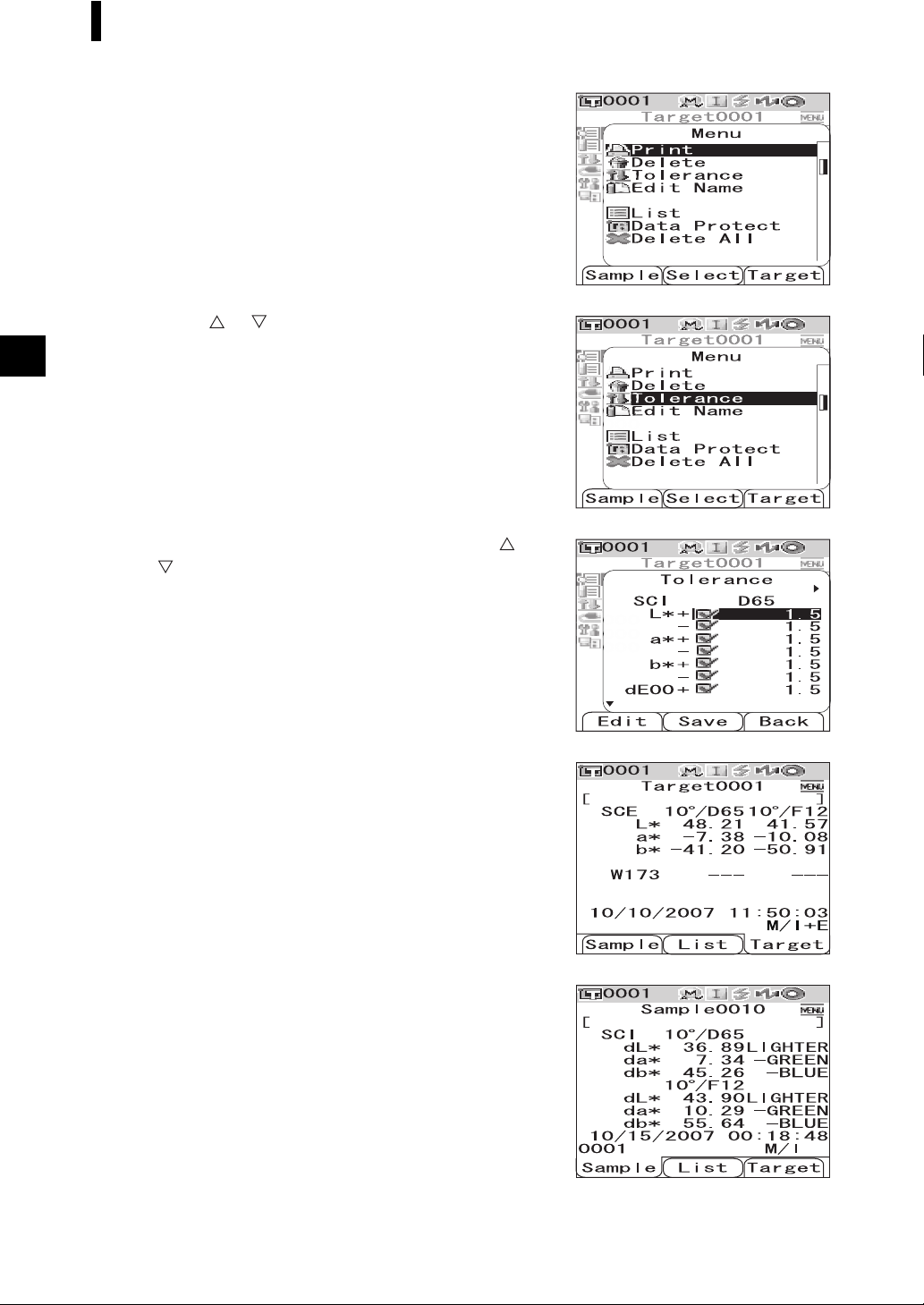
Pass/Fail Judgment for Color Difference
Press the [MENU] button.
3
The <Menu> screen is displayed.
Use the or button of the cross key to move
4
the cursor to “Tolerance” and then press the
[SAVE/SEL] button.
The <Tolerance> screen is displayed.
• To display the other tolerance setting items, press the or
button of the cross key.
E-92
Make sure that the values are set properly, and
5
then press the [SAVE/SEL] button.
The <Target> screen is displayed.
Press the [SAMPLE] button.
6
The <Sample> screen is displayed.
Page 97

Place the specimen measuring port on the
7
specimen, and press the measuring button.
The specimen is measured and the judgment results are
displayed according to the display type specified for the
display conditions.
• When the display type is “Absolute” or “Abs. & Diff.”
The values which failed the judgment are highlighted in red.
• When the display type is “Judge”
When at least one item failed the judgment, “Fail” is displayed; when all items passed the judgment,
“Pass” is displayed.
• When the judgment result is “Pass”, the results are
displayed as the screen on the right according to the
condition setting at the time of the measurement.
Pass/Fail Judgment for Color Difference
• When the judgment result is “Fail”, the results are
displayed as the screen on the right according to the
condition setting at the time of the measurement.
M
emo
• When “Judge” is selected as the display type, “Pass” will be displayed only when all the items have passed the judgment.
• When “Absolute” or “Abs. & Diff.” is selected as the display type, the values for the items which have failed the
judgment will be highlighted in red.
• If the tolerances have not been set, or the target color data of the number selected for the measurement has been
deleted, “None” will be displayed instead of the judgment results.
• When the screen is turned OFF by the power save function, press any of the measuring or control buttons to turn
ON the screen, confirm that (Ready to measure) is displayed or Ready lamp is green, and then press the
measuring button.
E-93
Page 98

Connecting to an External Device
The CM-700d/600d features both USB and Bluetooth capability. You can establish data communication
or print data by connecting the instrument to a PC with the supplied USB cable IF-A17, or by connecting
it to a PC or a printer via Bluetooth.
Note
When the instrument is exposed to strong external static electricity during communication with an external
device, the communication may be interrupted. In this case, turn the power OFF and then turn it ON again.
Connecting a Personal Computer
You can establish connection between the CM-700d/600d and a PC by connecting them with a USB
cable or by using the Bluetooth capability of the instrument.
Note
• To use the Bluetooth capability to establish connection to a PC, the PC must be equipped with a Bluetooth
adapter and the Bluetooth communication link must be opened by using the utility software supplied with the
adapter.
• The USB cable connection will be given priority over the Bluetooth communication link.
M
emo
• When connected to a PC, the instrument enters the communication mode automatically. The LCD screen displays
“Communicating” and the measuring and control buttons are disabled.
• If a command to enable the measuring button is sent from the PC to the instrument, you can use the measuring
button to start measurement. Note, however, that, in this case, the measured data is not stored in the memory of
the instrument, but is transferred to the PC.
• To connect the instrument with a PC, it is recommended that you use software that enables connection and
operation of the instrument (such as the optional Color Data Software SpectraMagic NX CM-S100w).
Connecting the Instrument with a USB Cable
Connect the instrument to a PC with the supplied USB cable IF-A17 (2 m).
Note
• To connect the instrument to a PC, you need to install the USB driver for the CM-700d/600d. Install the USB
driver supplied with the software that enables connection and operation of the instrument.
• The instrument is not designed to be powered via the USB cable. You need to connect the AC adapter or install
batteries in the instrument.
• Make sure that the USB connector plug is oriented correctly and connected securely.
• When connecting/disconnecting the USB cable, be sure to hold the connector plug. Do not pull on or forcibly
bend the cable. Otherwise, wire breakage may result.
• Make sure that the cable has sufficient length. Putting tension on the cable may cause connection failure or
wire breakage.
• To connect the USB cable connector, check the shape of the receptacle (connection terminal) and insert the
connector fully until it is secured.
M
emo
The USB communication port of the instrument conforms to USB 1.1.
E-94
Page 99

Connecting to an External Device
[Operating Procedure]
In general, a USB cable can be connected/disconnected while the instrument is turned ON, however, you
need to turn OFF the instrument in the procedure below.
Turn OFF the instrument (Slide the Power
1
switch to “ ”.).
Open the connector protection cover and
2
connect the B connector of the USB cable to
the USB connection terminal.
Connect the A connector of the USB cable to
3
the USB port of the PC.
• Fully insert the connector and ensure secure connection.
Turn ON the instrument (Slide the Power
4
switch to “|” .).
• When you are prompted to install the USB driver,
specify the USB driver included with the software and
complete the installation.
Connecting the Instrument via Bluetooth Communication
Use the built-in Bluetooth capability of the instrument to establish connection between the instrument
and a PC.
Note
• The Bluetooth capability of the instrument enables data communication with a PC equipped with a Bluetooth
adapter, or data printout with a Bluetooth-capable printer. Note, however, that a PC and a printer cannot be
connected simultaneously.
• The USB cable connection and Bluetooth communication link cannot be used simultaneously. When both
connections are made, priority is given to the USB cable connection.
E-95
Page 100

Connecting to an External Device
M
emo
To use the Bluetooth capability of the instrument to connect a PC, you need to prepare both the instrument and the
PC to establish Bluetooth communication. For details, refer to the instruction manual of the Bluetooth adapter.
Preparation of the Instrument
Set the Bluetooth capability of the instrument to ON.
[Operating Procedure]
Hold down the [MENU] button and press the
1
button of the cross key.
The <Option> screen is displayed.
Use the or button of the cross key to move
2
the cursor to “Communication” and then press
the [SAVE/SEL] button.
The <Communication> screen is displayed.
E-96
Use the or button of the cross key to move
3
the cursor to “Bluetooth” and then press the
[SAVE/SEL] button.
The <Bluetooth> screen is displayed.
Use the button of the cross key to move the
4
cursor to “ON” and then press the [SAVE/SEL]
button.
The Bluetooth capability of the instrument is set to ON and the
screen returns to the <Communication> screen.
 Loading...