

Page 1
Page 2
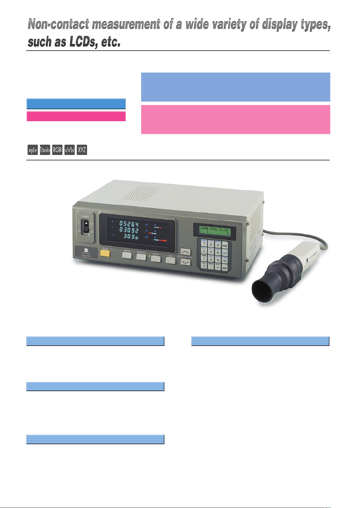
Photo shows Universal Measuring Probe
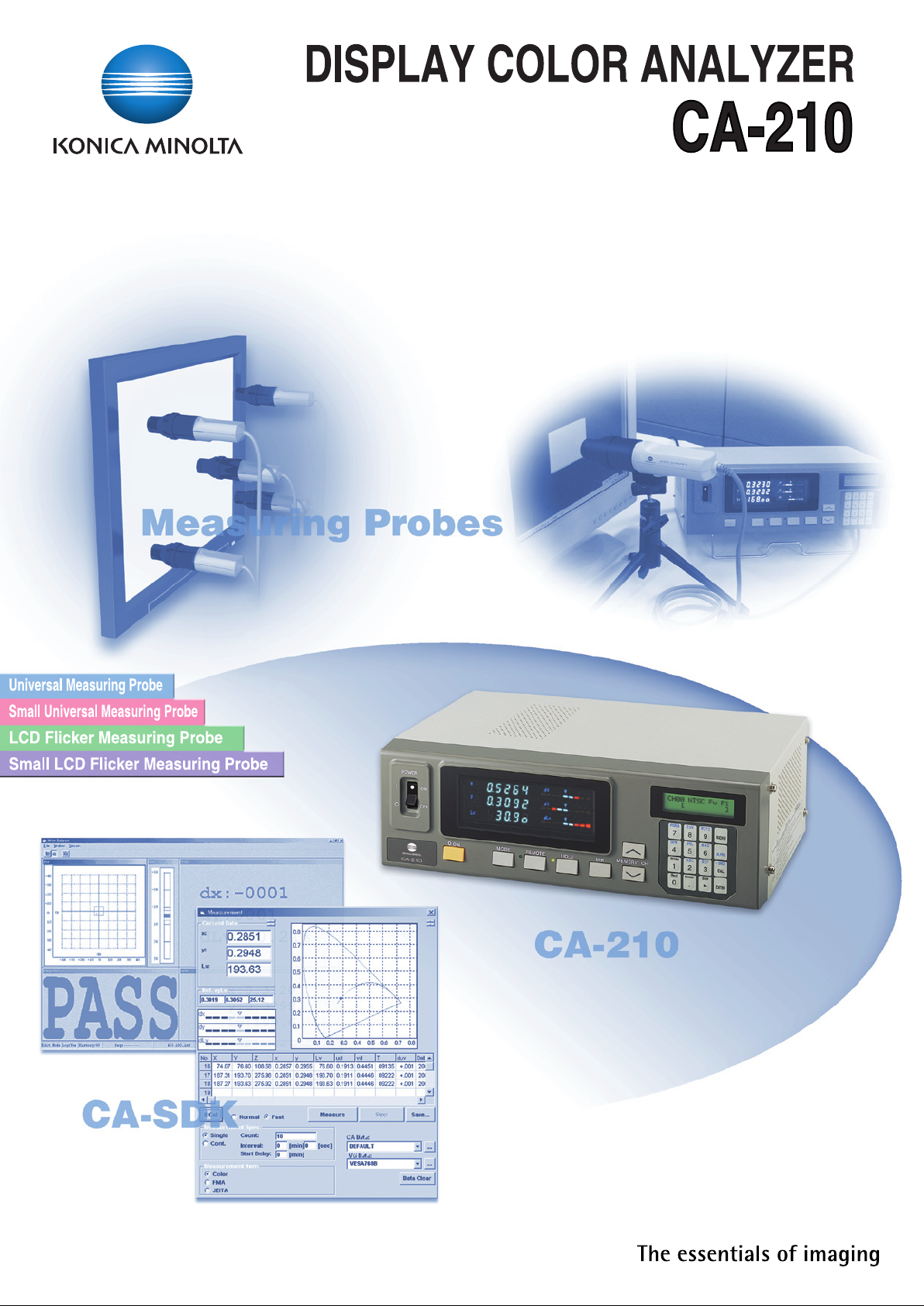
DISPLAY COLOR ANALYZER
CA-210
Select the probe among the following four types.
For LCD flicker measurement, use the LCD Flicker Measuring Probe or Small LCD Flicker Measuring Probe (see other side).
� Universal Measuring Probe CA-PU12
(Measurement area φ27 mm / Cable length: 2 m)
� Universal Measuring Probe CA-PU15
(Measurement area φ27 mm / Cable length: 5 m)
� Small Universal Measuring Probe CA-PSU12
(Measurement area φ10 mm / Cable length: 2 m)
� Small Universal Measuring Probe CA-PSU15
(Measurement area φ10 mm / Cable length: 5 m)
Up to five probes can be connected to a single main body. Universal Measuring Probes, Small Universal Measuring
Probes, LCD Flicker Measuring Probes and Small LCD Flicker Measuring Probes can be connected simultaneously to
a single main body.
(To connect multiple probes, the optional four-point extension board (CA-B14) is necessary.)
Applications
Rear Projector, PDP, LCD, OLED, FED
Chromaticity Inspection / Adjustment
Quality Control of Chromaticity.
White-Balance Inspection / Adjustment
Gamma Inspection / Adjustment.
Contrast Inspection / Adjustment
FASTER EASY TO USE
ACCURA
TE
LOW LUMINANCE
• The luminance and chromaticity of display can
be measured as fast as 20 times per second
(maximum), enabling faster Gamma
measurement.
• Precise measurement can be obtained at low
luminance, enabling lower luminance and highaccuracy contrast measurement.
Range of luminance for chromaticity measurement
: 0.1 to 1000 cd/m2 (Universal Measuring Probe)
0.3 to 3000 cd/m2 (
Small Universal Measuring Probe
)
• Accuracy of ±0.002 for White, ±0.004 for R,G,B.
(Chromaticity)
• CIE 1931 Standard Observer XYZ Filter.
• Matrix measurement enables high accuracy for
not just white, but for monochrome colors as well.
• The measurement position can be easily
confirmed by pointing function.
• Short measuring distance of 30 mm enables
compact measuring system.
• Precise measurement can be obtained without
the influence of the outside light by short
measuring distance and the rubber hood
(standard accessory).
• Special optical design limits acceptance within
narrow angle of aperture. It eliminates the
influence of viewing. Acceptance angle:
±2.5˚
(Universal Measuring Probe) ,
±5˚ (Small
Universal Measuring Probe)
• 4-digit display for chromaticity enables more
precise data readings.
• Expandable up to 5 measuring probes. (Requires
expansion board CA-B14)
• USB connection provided as standard, so it can
be connected even to computers without serial
ports.
Universal Measuring Probe
Small Universal Measuring Probe
Page 3

θ1
θ2
θ3
θ'1
θ'
3
Optical system of conventional
measuring instruments
Measurement position and incident
angle of conventional instrument
ψ1
ψ
2
ψ3
Measurement position and incident
angle of CA-210
Optical System Features
The CA-210 uses a special optical system suitable for providing
measurements of LCD panels.
The main components of the optical system are the objective lens, optical
fiber block, on-chip lenses, and sensor. The light from the light source is
focused onto the receiving window of the optical fiber block. The focused
light is mixed inside the optical fiber block and split into 3 parts, which are
then guided to the receiving areas of the x, y, z sensors. Here, the light is
further focused by the on-chip lenses onto the sensors themselves.
Low-Luminance Measurement
A key point in making it possible to accurately take measurements at low-luminance levels is to
minimize the light loss in guiding the received light to the sensors.
In a conventional system, the received light passes through the objective lens and is focused
immediately on the 3 sensors (x, y, z sensors). A problem with this method is that some of the light
is focused on areas other than the sensor, so the light loss is large.
The CA-210 uses optical fibers, so the light loss due to transmission of the light to the sensors is
relatively low compared to conventional methods. Specifically, the light received by the lens is
focused on the optical fiber block receiving window. The light then passes through optical fibers
directly to on-chip lenses, which focus the light onto the sensors. As a result of this, light
transmission loss is eliminated and measurements at low luminance levels are made possible.
Narrow Viewing Angle/Uniform Viewing Angle
When a person looks at a display, they view the emitted light within a relatively narrow angle.
Because of this, in order to obtain measured values which correspond well with the luminance and
chromaticity perceived by a person, it is necessary for the measuring instrument to have the same
narrow viewing angle. In addition, since LCDs have viewing-angle characteristics, measurements
at different viewing angles will result in different measured values. IEC 61747-6, which defines the
measurement method for LCDs, specifies that the viewing angle of the measuring instrument for
evaluating LCDs should be within 5°. (The viewing angle is shown by θ1, θ2, θ3 and ψ1, ψ2, ψ3.)
The CA-210 has a viewing angle of 5°, and so meets the requirements of the IEC standard.
For a conventional measuring instrument, when the measuring head has been set so that the
measurement axis is perpendicular to the surface of the emitting surface of the measurement
subject, differences in the measurement position do not result in great differences in the viewing
angle itself (shown as θ1, θ2, θ3 in the figure), but if we look at the incident angle relative to the
normal to the emitting surface (shown as a dotted line in the figure), we see that the maximum
angles (shown as θ'1 and θ'3 in the diagram) are very different. At the edges of the measurement
area, light from far outside the viewing angle is received.
By using a special optical system in the CA-210, the angle of the received light is symmetrical
about the normal to the emitting surface for every point within the measuring area (φ27 mm). Since
the viewing angle of the CA-210 is 5°, the light received would be only the light within ±2. 5° relative
to the normal to the emitting surface (shown as a dotted line in the figure).
Optical fiber block SensorObjective lens
CA-210 optical system
Universal
Measuring Probe
CA-PU12 (2 m)
CA-PU15 (5 m)
Small Universal
Measuring Probe
CA-PSU12 (2 m)
CA-PSU15 (5 m)
LCD Flicker
Measuring Probe
CA-P12 (2 m)
CA-P15 (5 m)
Small LCD Flicker
Measuring Probe
CA-PS12 (2 m)
CA-PS15 (5 m)
(Hood and Lens Cap included)
Muli-Probe (Optional)
System Diagram
4-Probe Expansion Board
CA-B14
(Optional)
Standard Hood for CA-210
CA-H10(Standard)
or
Small Hood for CA-210
CA-HS10(Standard)
Select the probe among the following four types.
Universal Measuring Probe
CA-PU12 (2 m)
CA-PU15 (5 m)
Small Universal Measuring Probe
CA-PSU12 (2 m)
CA-PSU15 (5 m)
LCD Flicker Measuring Probe
CA-P12 (2 m)
CA-P15 (5 m)
Small LCD Flicker Measuring Probe
CA-PS12 (2 m)
CA-PS15 (5 m)
Standard Lens Cap for CA-210
CA-H11(Standard)
or
Small Lens Cap for CA-210
CA-HS11(Standard)
CA-210
PC (Commercially
available)
PC-AT compatible
AC Power Cord
(Standard)
PC Software
for Color Analyzer
CA-SDK(Standard)
Page 4

Transmissive / Active Matrix Driven
semi-transmissive LCD Passive Matrix Driven
Rear Screen LCD Active Matrix Driven
Projector Passive Matrix Driven
DLP
CRT
OLED Active Matrix Driven
Passive Matrix Driven
PDP
FED
CA-210
Universal Measurring Probe
CA-PU12 / CA-PU15
Small Universal Measurrin
g Probe
CA-PSU12 / CA-PSU15
LCD Flicker Measurring Prob
e
CA-P12 / CA-P15
Small LCD Flicker Measurring Prob
e
CA-PS12 / CA-PS15
Standard
measurements
LCD flicker
measurements
This table is based on the most popular method for controlling emission intensity for
each display type.
(∗1) Measurements of displays using certain control methods are not possible. For
details of measurement compatibility, contact your nearest Minolta representative.
Examples for which measurement is not possible:
• Displays which use PWM, etc. for control of emission intensity.
• Displays with backlights which emit intermittently.
• Displays which write black for each frame,
etc.
(∗2) Although the CA-100Plus can handle the emission intensity variation, the
instrument has a wide acceptance angle which makes it unsuitable for
measurements of LCDs with strong viewing-angle dependency.
Recommended
Measurement possible with restrictions, but probes marked with are recommended
Measurement not possible
LCD Flicker Measuring Probe and Small LCD Flicker Measuring Probe are unsuitable for Measurements of CRTs.
Please request a CA-100Plus catalog for further information.
DISPLAY COLOR ANALYZER
CA-210
Same model as CA-210
measuring probes sold until May 2003.
Select the probe among the following four types.
� LCD Flicker Measuring Probe CA-P12
(Measurement area φ27 mm / Cable length: 2 m)
� LCD Flicker Measuring Probe CA-P15
(Measurement area φ27 mm / Cable length: 5 m)
� Small LCD Flicker Measuring Probe CA-PS12
(Measurement area φ10 mm / Cable length: 2 m)
� Small LCD Flicker Measuring Probe CA-PS15
(Measurement area φ10 mm / Cable length: 5 m)
Up to five probes can be connected to a single main body. Universal Measuring Probes, Small Universal Measuring
Probes, LCD Flicker Measuring Probes and Small LCD Flicker Measuring Probes can be connected simultaneously to
a single main body.
(To connect multiple probes, the optional four-point extension board (CA-B14) is necessary.)
CRT COLOR ANALYZER
CA-100Plus
LCD Flicker Measuring Probe
Small LCD Flicker Measuring Probe
Measuring Probe
High luminance Measuring Probe
Select the probe among the following four types.
� Measuring Probe CA-P02
(Cable length: 2 m)
� Measuring Probe CA-P05
(Cable length: 5 m)
� High luminance Measuring Probe CA-PH02
(Cable length: 2 m)
� High luminance Measuring Probe CA-PH05
(Cable length: 5 m)
Up to five probes can be connected to a single main body. Measuring Probes and High luminance Measuring Probes
can be connected simultaneously to a single main body
.
(To connect multiple probes, the optional four-point extension board (CA-B04) is necessary.)
Applicability of CA series for different display types
LCD Flicker Measuring Probe is applied to the “Flicker measuring function". Because of this it is not able to measure the display whose emission
intensity fluctuates in single frame scanning period.
Page 5

CH01EXT FaP1
[EXTD-1.50]
POWER
0-CAL
MODE REMOTE HOLD MR
MEMORYCH
PQRS7TUV8WXYZ
MENU
ALPHA
9
GHI4JKL5MNO LOCK
6
CAL
White1ABC2DEF-SPACE
3
ENTER
Red0Green.Blue
ON
OFF
x
y
v
∆x
∆y
∆Lv
This is an example of gamma adjustment system. User can
create adjustment system by PC Software for Color
Analyzer CA-SDK which comes as standard accessory.
Software controls CA-210 and pattern generator to obtain
color and chromaticity data with each out put level. After
calculating correction factor of gamma curve, software will
write the look up table of coefficient to monitor firmware.
The white balance adjustment system can be constructed
by a similar method.
Construction of Gamma Adjustment System
User's own matrix correction factor is set to the memory
channels by measuring three monochrome colors (R, G, B
and W) of known values and setting the obtained calibration
values (xyLv) and emission characteristic to the instrument.
Once this factor is set,a the measured values will be
displayed after correction by this factor and output each
time measurement is taken.
Performing matrix calibration enables high-accuracy
measurements of displays that provide colors through
additive color mixing of three monochrome colors (R, G and B).
Since the matrix correction factor obtained from Minolta's
calibration standard has been set, measured values
calculated based on this factor will be acquired when this
instrument is used for the first time since shipment from the
factory.
Matrix Calibration
Display Unit
CA-210
Software made
with SDK
Pattern
Generator
Input of
test pattern
luminance
Pattern
Signal
Writing gain
and cutoff level
Command
to CA-210
Data from
CA-210
Gamma Adjustment System
Sample software Gamma
PC Software for Color Analyzer
CA-SDK (Standard accessory)
Standard accessory SDK helps create software easily
according to needs.
Sample software is bundled; you can start data collection
easily.
Windows®and Excel®are a trademark of Microsoft Corporation in the USA and
other countries.
Required system
OS : Windows®98,2000,ME,XP (x64 Edition not supported)
Sample software (Standard)
Cal
CA-210 can be corrected in the matrix calibration method using
Konica Minolta's spectroradiometer CS-1000A.
Color
The measurement data of CA-210 can be acquired into the PC.
Drift tests, LCD stability test and so on can be performed easily.
The acquired data can be read with Excel®or other spreadsheet
software.
Contrast
Multi-point measurement (5, 9, or 25 points) can be made for
white uniformity and contrast measurement.
Gamma
R, G, B, and W gamma measurements for gradations of 16, 32,
64, 128, and 256 steps.
Sample software Color
Example of White Balance Adjustment Software made by SDK
Page 6

Dimensions (Units : mm)
340
216
127
11017
70
204200047.4
30.2
10
φ44
10
30.2
φ44
φ30
φ49
232200047.4
88
98
108
116
126
136
Main Body
Universal Measuring Probe
LCD Flicker Measuring Probe
Small Universal Measuring Probe
Small LCD Flicker Measuring Probe
ISO screw
ISO screw
Tripod socket
ISO screw
ISO screw
Tripod socket
φ26
φ49
CA-210 (
Universal Measuring Probe
)
φ27 mm
±2.5˚
30±10 mm
0.01 to 1000 cd/m
2
0.10 to 1000 cd/m
2
0.10 to 0.99 cd/m20.2%+1 digit
1.00 to 1000 cd/m20.1%+1 digit
0.10 to 1000 cd/m
2
0.10 to 4.99 cd/m2±0.008
for white
5.00 to 39.99 cd/m2±0.005
for white
40.00 to 1000 cd/m2±0.003
for white
160 cd/m
2
±0.002
for white
(±0.004 for monochrome)∗2
0.10 to 0.19 cd/m20.015 (2 σ)
0.20 to 0.49 cd/m20.008 (2 σ)
0.50 to 1.99 cd/m20.003 (2 σ)
2.00 to 1000 cd/m20.001 (2 σ)
5 (4.5) 0.10 to 3.99 cd/m
2
20 (17 ) 4.00 cd/m2or higher
Main body: 340 (W) × 127 (H) × 216 (D)mm,
Probe: φ49 × 204
mm
Main body: 3.58 kg, Probe: 520 g
Detector: Silicon photo cell
By LED
Displayed in 4 or 3-digit value (Can be chosen)
±2%±1 digit of reading
(temperature : 23°C±2°C,relative humidity : (40±10)%)
-------
-------
-------
-------
-------
-------
-------
-------
------xyLv, XYZ, T∆uvLv, u'v'Lv, RGB analyze
Chromaticity is displayed up to fourth decimal place.
(Three-digit indication can be chosen.)
∆x∆y∆Lv, R/G B/G ∆G, ∆R B/R G/R
16 characters by 2 lines (with backlight)
NTSC, PAL, EXT, UNIV, INT
Vertical synchronizing frequency: 40 to 200 Hz
100 channels
Standard function
RS-232C (38,400 bps or below), USB (Rev.1.1)
Max. 5 points(Use 4-Probe Expansion Board CA-B14)
SDK software (supplied as standard accessory)
100 – 240 V~, 50–60 Hz, 50 VA
CA-210 (
Small Universal Measuring Probe
)
φ10 mm
±5˚
30±5 mm
0.01 to 3000 cd/m
2
0.30 to 3000 cd/m
2
0.30 to 2.99 cd/m20.2%+1 digit
3.00 to 3000 cd/m20.1%+1 digit
0.30 to 3000 cd/m
2
0.30 to 14.99 cd/m2±0.008
for white
15.00 to 119.99 cd/m2±0.005
for white
120.00 to 3000 cd/m2±0.003
for white
160 cd/m
2
±0.002
for white
(±0.004 for monochrome)∗2
0.30 to 0.59 cd/m20.015 (2 σ)
0.60 to 1.49 cd/m20.008 (2 σ)
1.50 to 5.99 cd/m20.003 (2 σ)
6.00 to 3000 cd/m20.001 (2 σ)
5 (4.5) 0.30 to 11.99 cd/m
2
20 (17 ) 12.00 cd/m2or higher
Main body: 340 (W) × 127 (H) × 216 (D)mm,
Probe: φ49 × 232
mm
Main body: 3.58 kg, Probe: 540 g
CA-210 (
LCD Flicker Measuring Probe
)
φ27 mm
±2.5˚
30±10 mm
0.01 to 1000 cd/m
2
0.10 to 1000 cd/m
2
0.10 to 0.99 cd/m20.2%+1 digit
1.00 to 1000 cd/m20.1%+1 digit
0.10 to 1000 cd/m
2
0.10 to 4.99 cd/m2±0.005
for white
5.00 to 19.99 cd/m2±0.004
for white
20.00 to 1000 cd/m2±0.003
for white
160 cd/m
2
±0.002
for white
(±0.004 for monochrome)∗2
0.10 to 0.19 cd/m20.010 (2 σ)
0.20 to 0.49 cd/m20.005 (2 σ)
0.50 to 0.99 cd/m20.002 (2 σ)
1.00 to 1000 cd/m20.001 (2 σ)
5 (4.5 ) 0.10 to 1.99 cd/m
2
20 (17 ) 2.00 cd/m2or higher
Main body: 340 (W) × 127 (H) × 216 (D)
mm,
Probe: φ 49 × 204
mm
Main body: 3.58 kg, Probe: 520 g
5 cd/m2or higher
0.0 to 100 %
±1 % (Flicker frequency: 30 Hz AC/DC 10 % sine wave)
±2 % (Flicker frequency: 60 Hz AC/DC 10 % sine wave)
1 % (2 σ) (Flicker frequency: 20 to 65 Hz AC/DC 10 % sine wave)
5 cd/m2or higher
±0.5 dB (Flicker frequency: 30 Hz AC/DC 10 % sine wave)
0.3 dB (2 σ) (Flicker frequency: 30 Hz AC/DC 10 % sine wave)
16 measurements/sec. (16 measurements/sec.)
0.5measurements/sec. (0.3 measurements/sec.) ∗5
xyLv, XYZ, T∆uvLv, u'v'Lv, RGB analyze
Chromaticity is displayed up to fourth decimal place.
(Three-digit indication can be chosen.)
Flicker (Contrast method) ∗3
∆x∆y∆Lv, R/G B/G ∆G, ∆R B/R G/R, Flicker (Contrast method) ∗3
Vertical synchronization frequency: 40 to 200 Hz (Luminance or chromaticity measurement), 40 to 130 Hz (Flicker measurement)
CA-210 (
Small LCD Flicker Measuring Probe
)
φ10 mm
±5˚
30±5 mm
0.01 to 3000 cd/m
2
0.30 to 3000 cd/m
2
0.30 to 2.99 cd/m20.2%+1 digit
3.00 to 3000 cd/m20.1%+1 digit
0.30 to 3000 cd/m
2
0.30 to 14.99 cd/m2±0.005 for white
15.00 to 59.99 cd/m2±0.004 for white
60.00 to 3000 cd/m2±0.003 for white
160 cd/m
2
±0.002 for white
(±0.004 for monochrome)∗2
0.30 to 0.59 cd/m20.010 (2 σ)
0.60 to 1.49 cd/m20.005 (2 σ)
1.50 to 2.99 cd/m20.002 (2 σ)
3.00 to 3000 cd/m20.001 (2 σ)
15 cd/m2or higher
15 cd/m2or higher
5 (4.5) 0.30 to 5.99 cd/m
2
20 (17) 6.00 cd/m2or higher
Main body: 340 (W) × 127 (H) × 216 (D)mm,
Probe: φ49 × 232
mm
Main body: 3.58 kg, Probe: 540 g
Item
Receptor
Measurement area
Acceptance angle
Pointing function
Measurement distance
Display range Luminance
Chromaticity
Luminance
Measurement range
Accuracy (for white)
∗1
Repeatability(2 σ)
∗1
Chromaticity
Measurement range
Accuracy∗1
(temperature : 23°C±2°C,
relative humidity : (40±10)%)
Repeatability∗1
Flicker Contrast
Measurement range
method Display range
Accuracy
Repeatability
Flicker JEITA
Measurement range
method ∗3 Accuracy
Repeatability
Measurement xyLv∗4
speed
(measurements/sec. )
Flicker Contrast
Flicker JEITA∗3
Display Digital
Analog
LCD
SYNC mode
Object under measurement
Memory channel
Analyzer function
Interface
Multi-point Measurement
Software
Operating temperature/humidity range
Storage temperature/humidity range
Input voltage range
Size
Weight
Specifications
∗1 : The chromaticity and luminance are measured under Konica Minolta’s condition (standard LCD(6500 K, 9300 K) is used).
∗2 : The luminance for monochrome is measured when the reading of luminance for white is 160 cd/m2.
∗3 : Measurement of flicker (JEITA method) is supported by SDK software.
∗4 :
Measuring probe connected to probe connector P1 only,used USB (used RS-232C
Baud rate: 38400 bps
)
∗5 : Measured by Konica Minolta’s PC (P3-600 MHz)
• Specifications are subject to change without notice.
0 to 28°C : relative humidity 70 % or less with no condensation 28 to 40°C : relative humidity 40 % or less with no condensation
Temperature : 10 to 28°C; relative humidity 70 % or less with no condensation Luminance change : ±2 % ±1 digit of reading for white
Chromaticity change ±0.002 for white, ±0.006 for monochrome from reading of Konica Minolta's standard LCD∗1, 160.0 cd/m2, with 23°C 40 %
AGMEP
K
Printed in Japan9242-4885-15
©2003 KONICA MINOLTA SENSING, INC.
SAFETY PRECAUTIONS
8
For correct use and for your safety, be sure to read
the instruction manual before using the instrument.
Always connect the instrument to the
specified power supply voltage.
Improper connection may cause a fire
or electric shock.
Certificate No : JQA-E-80027
Registration Date: March 12,1997
Certificate No : YKA 0937154
Registration Date: March 3, 1995
 Loading...