

Page 1

C-101
SERVICE MANUAL
Page 2

CONTENTS
GENERAL, MECHANICAL/ELECTRICAL
1. SPECIFICATIO NS .............. ........... ................ ............... ............... ............... ..... M-1
2. PARTS IDENTIFICATION ...............................................................................M-1
3. CROSS-SECTIONAL VIEW ............................................................................M-2
4. DRIVE SYSTEM ............. .... .... .... ... ................ ... .... ................ ... ................ ... .....M-3
5. ELECTRICAL COMPONENT LAYOUT ...........................................................M-4
6. MECHANICAL DESCRIPTIONS .....................................................................M-5
6-1. Mechanical Operation and Control of Paper Plate Lifting ........................M-5
6-2. Mechanical Operatio n and Cont rol of Paper Take-Up, Separation,
and Transport ..........................................................................................M-7
6-3. Paper Empty Detecting Mechanism ........................................................M-9
6-4. Paper Dehumidifier Heater ......................................................................M-10
DIS/REASSEMBLY, ADJUSTMENT
1. DISASSEMBLY ...............................................................................................D-1
2. PAPER WIDTH CONVERSION .......................................................................D-3
3. IMAGE POSITION ADJUSTMENT ..................................................................D-5
MISFEED DETECTION&
MALFUNCTION DETECTION
1. PAPER MISFEED DETECTION ......................................................................T-2
1-1. Misfeed Dete c tio n Timin g ...... .... ............... ................ ............... ............... .T-2
1-2. Misfeed Trou b les h oot in g Proce du res ............... ........................... ............T-2
2. MALFUNCTION DETECTION .........................................................................T-4
2-1. Malfunction Detection Timing ..................................................................T-4
2-2. Malfunction Troubleshooting Procedures ................................................T-4
i
Page 3

GENERAL,
MECHANICAL/
ELECTRICAL
Page 4
1 SPECIFICATIONS
Name : C-101
Type : Cassette type large capacity tray
Installation : Fixed to the copier using a dedicated Base with Slide Rails
T y pe of Paper :
Size of Paper : A4 crosswise, B5 lengthwise, B5 crosswise, Letter
Capacity : 1,000 sheets
Power Supply : DC5V, DC24 V (supplied from the copier)
Power Consumpt ion : 30W or less
Dimensions : 358 (W) x 446 (D) x 289 (H) mm
Weight : 10.7 kg (main body + rails)
Environmental Requirements: Same as the copier
Plain paper weighing 60 to 90 g/m
crosswise
2
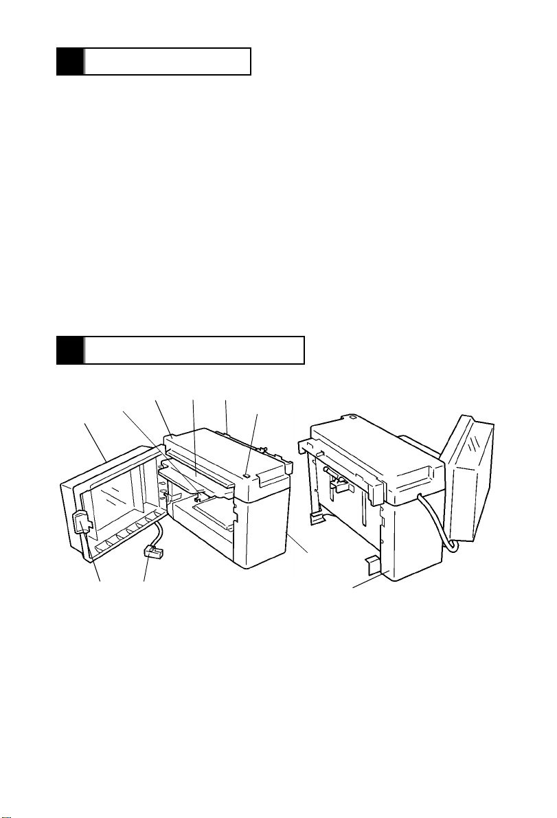
2 PARTS IDENTIFICATION
34
2
1
9
1. LCT Door
2. Edge Guide
3. Top Cover
4. Paper Plate
5. Paper Transport Port
8
5
4605M006AA
6
7
10
6. Paper Plate Descent Switch S1B
7. Front Cover
8. Relay Cord
9. Door Unlocki ng Lever
10. Rear Cover
M-1
4605M007AA
Page 5

3 CROSS-SECTIONAL VIEW
Paper Plate Upper Position Sensor PC2
Paper Empty Sensor PC3
LCT Door
Edge Guide
Paper Feed Roll
Paper Separator
Roll
Paper Take-Up Roll
Paper Plate
M-2
4605M008AA
Page 6
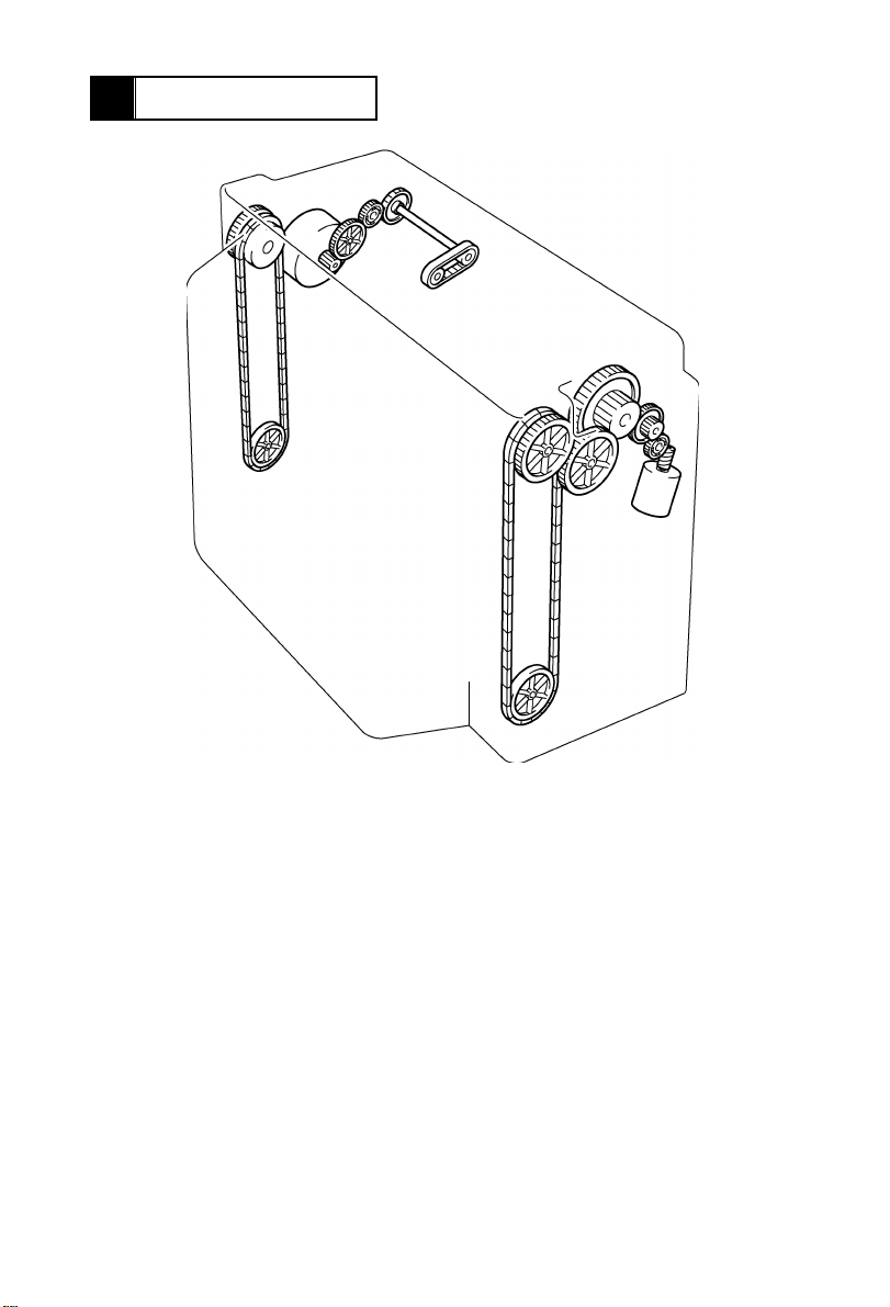
4 DRIVE SYSTEM
A
B
4605M009AA
A : Paper Take-Up Motor M2 : Drives the Paper Take-Up, Feed, and Separator Rolls.
B : Elevator Motor M1 : Moves the Paper Plate up and down.
M-3
Page 7
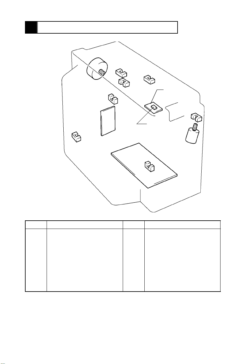
5 ELECTRICAL COMPONENT LAYOUT
M2
PC2
PC6
PWB-A
PC4
Symbol Name Symbol Location
PWB-A
PWB-B
M1
M2
H1
S1B
Master Board
Paper Plate Descent Switch
Board
Elev ator Motor
Paper Take-Up Motor
Paper Deh um i dif ie r Heate r
Paper Plate Descent Switch
PC1
PC2
PC3
PC4
PC5
PC6
PC7
PC5
PC3
H1
PC7
Elevator Pulse Sensor
Paper Plate Upper Position
Sensor
Paper Empty Sensor
Paper Plate Lower Position
Sensor
Paper Take-Up Sensor
LCT Set Detecting Sensor
LCT Door Ope n/C l os e Det ec ting
Sensor
PWB-B
S1B
M1
4605M010AA
PC1
M-4
Page 8
6 MECHANICAL DESCRIPTIONS
<
6-1. Mechanical Operation and Control of Paper Plate Li fting
• The Paper Plate is moved up and down by the chains and gears which are driven by Elevator Motor M1.
<M1 Turning Forward = Ascent>
Paper Plate Upper Position Sensor PC2
Elevator Motor M1
4605M011AA
M1 Turning Backward = Descent>
Paper Plate
Lower Position
Sensor PC4
4605M012AA
M-5
Page 9

<Mechanical Operation>
- Ascent Motion -
The LCT D oor is closed.
(LCT Door Open/Close Detecting Sensor PC7 is blocked L.)
Elevator Motor M1 turns forward. (The Paper Plate starts its ascent motion.)
The Paper Plate moves up and t he paper st ack blocks L Paper Plate
Upper Position Sensor PC2.
M1 is deen ergized. (The Paper Plate completes it s ascent motion.)
- Paper Take-Up Sequence -
Sheet s of pa pe r are tak en up.
The Paper Tak e-Up Roll gradually lowers to eventually unblock H PC2.
M1 turns forward to raise the Paper Take-Up Roll, thus blocking L PC2.
M1 is deenergiz ed.
✽ This sequence of operations is repeated to maintain a given pressure
between the paper stack and Paper Take-Up Roll.
- Descent Motion -
Paper Plate Descent Switch S1B is actuated or paper runs out.
M1 turns backward. (The Paper Plate starts its descent motion.)
The Paper Plate lowers to block L Paper Plate Lower Position Sensor PC4.
M1 is deenergiz ed. (The Paper Plate completes its descent motion.)
<Control>
• M1 is turned f orw ar d, backw a rd, stop pe d, a nd br ak ed by th e si gn al s out pu t fr o m IC 1A- 42
and 43 on Master Board PWB-A.
M1
Forward (Ascent) H L
Backward (Descent) L H
Stopped H H
Braked L L
IC1A
Pin 42 Pin 43
M-6
Page 10

6-2. Mechanical Operation and Control of Paper Take-Up, Sep-
aration, and Transport
<Paper Take-U p Mecha nical Operation>
The Start key is pressed. (The copy cycle is started.)
Paper Take-Up Motor M2 is energized.
Drive from M2 is transmitted via gears and belt.
The Paper Feed, Separator, and Take-Up Rolls turn counterclockwise.
Paper is transp orted through the LCT.
Paper Take-Up Motor M2
Paper Ta ke-Up Roll
4605M013AA
Paper Feed Roll
Paper Separator Roll
4605M002AA
M-7
Page 11

<Paper Separation Mechanical Operat ion>
• When two or more sheets of paper are taken up by the Paper Take-Up Roll, the paper
separating mechanism prevents the second and subsequent sheets of paper from being
fed together with the first on e. The mechanism consists of the Paper Feed Roll, Pap er
Separator Roll, and torque limiter.
• When only one sheet of paper is taken up:
The turning torque of the Paper Feed Roll is transmitted to the Paper Separator Roll via
the sheet of paper being fed in; however, it is greater than the static torque of the Paper
Separator Roll (torque limiter), which causes the Paper Separator Roll to be turned by
the Paper Feed Roll, thus transporting the sheet of paper.
• When two or more sheets of paper are taken up at the same time:
The coefficient of friction between the first sheet and the second and subsequent sheets
of paper is small and the static torque of the torque limiter keeps the Paper Separator
Roll stationary.This stops the second and subsequent sheets of paper from being fed in,
allowing only the first sheet of paper to be fed in.
- Single-Sheet Feed - - Multiple-Sheet Feed -
1285M012
<Paper Take-U p Control>
• Rotation of Paper Take-Up Motor M2 is controlled by the pulse signals output from IC2A1, 2, 4, and 17 of Master Board PWB-A.
IC2A Rotation
1LLHH
2HHLL
17 L H H L
4HLLH
1285M013
M-8
Page 12

6-3. Paper Empty Detecting Mechanism
<Paper Empty De tection Timin g>
1. The LCT Door is opened.
2. Paper Plate Descent Switch S 1B is pressed unde r normal operatin g conditions.
3. Paper Empty Sensor PC3 is blocked.
If Paper Plate Upper Position Sensor PC2 is unblocked wh en PC3 is bl ocked, the Paper
Plate is then lowered until Paper Plate Lower Position Sensor PC4 is blocked.
<Resetting Paper Empty C ondition>
1. Close the LCT Door.
2. Add paper (if the LCT has run out of paper).
Paper Plate Upper Position Sensor PC2
Paper Empty Sensor PC3
1258M020AA
M-9
Page 13

<Paper Empty Sensor PC3>
When Paper is Present When Paper in not Present
4605M003AA
1258M021AA
Paper Plate Upper Position Sensor PC2
When Top Level is Detected When Top Level is not Detected
4605M004AA
4605M005AA
6-4. Paper Dehumidifier Heater
• When paper in the LCT grows damp, its electrical resistance is decreased, which aggravates the image transfer efficiency resulting in void image and other image problems.
The Paper Dehumidifier Heater (20W) is provided to prevent this problem.
• The heater is turned ON when the power cord of the copier is plugged in, and kept ON at
all times except while the copier Main Motor M1 remains energized.
M-10
Page 14

DIS/REASSEMBLY,
ADJUSTMENT
Precautions for Disassembly, Reassembly, and Adjustment
1. Before attempting to disassemble the LCT, always make sure that no p ower is being
supplied from the copier.
2. While power is being supplied to the LCT, do not attempt to remove/install the print
jacks from/to the PWBs or unplug/plug in the connectors.
3. If the LCT is run with its covers removed, use care not to allow your clothing to be
caught in revolving parts.
4. The basic rule is do n ot run the LCT with an y of its par ts removed.
5. A toothed washer is used with the screw that secures the ground wire to ensure positive
conduction. Do not forget to include th is washer at reassembly.
6. To reassemble the LCT, reverse the order of disassembly unless otherwise specified.
7. Do not attempt to re move or loosen the screws to which red paint has been applied.
8. Screws to which blue paint has been applied may be removed; however, be sure to
make an adjustment after reinstalling the screws.
Purpose of Application of Red Paint
Red paint is applied to the screws of parts that cannot be readjusted, set, or reinstalled in
the field.
Page 15

1 DISASSEMBLY
4605D001AA
4605D002AA
4605D003AA
4605D004AA
Important
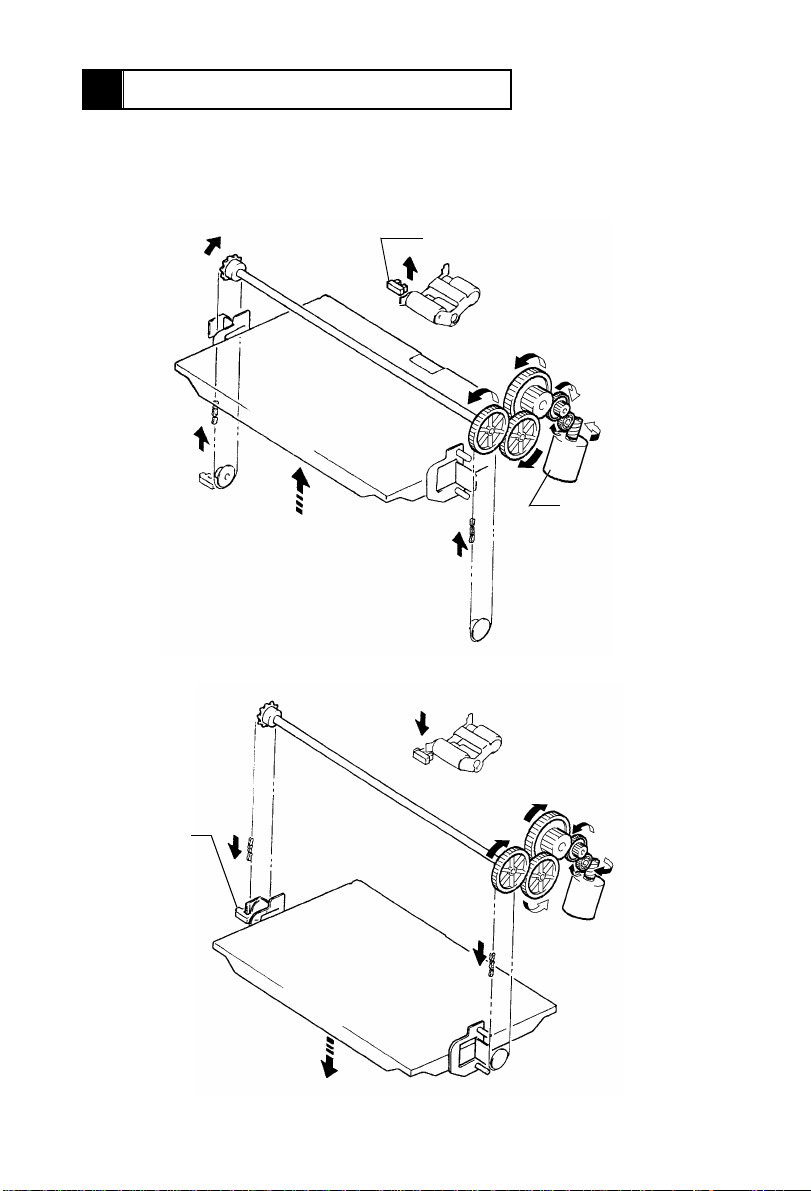
The Paper Plate must be lowered be fore att empting to start the disassembly pr ocedures.
1. Removal of the Paper Take-Up/Feed Rolls
1. Remove the Top Cover.
NOTE:
Unplug the connector for Paper Plate Descent
Switch S1B.
2. Snap off the C-clip from the Paper Feed Roll shaft
and remove the timi ng belt.
3. Unhooking the springs in the P aper Separator Roll
unit, slide the Paper Take-Up Roll Assy and
remove the bushing to remove the Paper T ake-Up
Roll Assy.
NOTE:
When the Paper Take-Up Roll Assy, use care not to
allow it to hit against Paper Plate Upper Position Sensor PC2.
4. Remove the Paper Feed Roll and one-way cl utch.
D-1
Page 16

5. Snap off the C-clip and p ull out the Paper Take- Up
4605D005AA
4605D006AA
4605D007AA
1258D013AA
4605D008AA
2. Removal of the Paper Separator Roll
1. Remove one screw that secures the Paper Sepa-
2. Unhooking the springs in the P aper Separator Roll
Roll shaft to remove the Paper Take-Up Roll.
rator Roll Assy.
unit, remove the Paper Separator Roll Assy.
3. Snap off the E-rings and remove the bushings on
both ends. Then, remove the Paper Separator Roll
shaft.
4. Snap off the E-ring and remove the Paper Separator Roll.
D-2
Page 17

2 PAPER WIDTH CONVERSION
4605U011AA
4605U012AA
4605U013AA
4605U014AA
1. Bring the Paper Plate to its uppermost position.
Slide the LCT away from the copier and remove the LCT
Door.
2. Loosen the two screws. Then, with the Top Cover
slightly raised, unplug the connector of Paper Plate
Descent Switch S1B.
Remove the Top Cover.
3. Remove the position ing screws of Edge G uides.
4. Remove the Edge Guides.
D-3
Page 18

5. Fi t the Ed ge G uide s in to th e sl ots co r res pon di n g to
4605U015AA
B
AC D D CA
B
4605U013AA
4605U012AA
4605U011AA
the paper size to be used.
- Slot-to-Paper-Size Correspondence A ... A4 crosswise
B ... Letter crosswise
C ... B5 crosswise
D ... B5 lengthwise
6. Slightly raising the Edge Guides, tighten the positioning screws.
7. Connect the Top Cover conn ector and reinstall the
Top Cover.
8. Reinstall the LCT Door.
D-4
Page 19

3 IMAGE POSITION ADJUSTMENT
1. Set the copi er into the Service mode and select
“Machine Adjust.”
4605D021CA
2. Select “PRT Area.”
4605D022CA
3. Select “Left Margin.”
4605D023CA
4605D024CA
4. Select “LCT” and press the Start key to let the
copier start a test print cyc le.
D-5
Page 20

4605D024CA
4605D020AA
Feeding Direction
4605D019AA
5. Mea s ure the void image width on the test print.
Specifications.....3 mm±1.5 mm
6. If the measurement falls ou tside the specified
range, adjust the void image width using ▲or
▼key.
Make a test print again to check for correct adjustment.
7. If the void image width does not fal l within the
specified range even through these adjustments
on the Touch Pane l, move the Rail Assy to the rear
or front to make a mechanical adjustment.
D-6
Page 21

MISFEED DETECTION&
MALFUNCTION DETECTION
General Precautions
1. When servicing the LCT with i ts covers removed, use utmost care to prevent your
hands, clothing and tools from being caught in revolving parts.
2. Before attempting to replace parts and unplugging connectors, make sure that no
power is being supplied from the copier.
3. In whatev er situat ions, terminals and PWB patterns other than connectors spec ified in
the text must not be shorted.
4. When creating a closed circuit and measuring a voltage across connector pins specified in the text, be sure to use the green wire (GND).
5. Keep all disassembled parts in good order and keep to ols under control so that none
will be lost or da ma ge d.
Reading the Text
1. If a component on a PWB or any other functional unit inc luding a motor is defective, the
text only instructs you to replace the whole PWB or functional unit and does not give
troubleshooting pr ocedure applicable within the defectiv e unit.
2. The text assumes tha t there are no breaks and short s in the harnesses and all connectors are plugged into the right positions.
Page 22

- Sensor Check Procedure -
<Procedure>
1. When a paper misfeed or malfunction occurs, identify the possibly defective cont rolled
part or parts on the circuit diagram.
2. Open the “State Confirm” screen, as selected from the Service Mode menu. Then,
show the screen that contains the part or parts picked out in step 1) from among Switch
1 (Paper) or Switch 2 (Option).
3. Force to change the status of the sensor sel ected and check at that time that the signal
state changes on the screen.
Example
If Paper Take-Up Senso r PC5 is considere d defective when a paper misfeed occurs:
<Procedure>
1. Remove the sheet of misfed paper.
2. Select “Switch 2 (Option)” of “State Confirm” available from the Service mode.
4605D025CA
3. Check that Pap. Trans is Off on the screen.
4. Mo ve the PC5 actuator with a sheet of paper to block PC5.
5. Check that the state of Pap. Trans. has changed to On from Off.
On: PC5 is operational.
Set : L CT-to-copier connector
Path Set : LCT Set Detecting Sensor PC6
Cover Open : LCT Door Open/Close Detecting Sensor PC7
Pap. Empty : Paper Empty Sensor PC3
Upr. Limit : Paper Plate Upper Position Sensor PC2
Lwr. Limit : Paper Plate Lower Position Sensor PC4
Pap. Trans : Paper Take-Up Sensor PC5
Off: PC5 is defective
T-1
Page 23

1 PAPER MISFEED DET ECTION
1-1. Misfeed Detection Timing
Type Detection Timing
Paper left When the copier Power Switch is turned ON or a paper mis-
feed or malfunct ion is reset, Paper Take-Up Sensor PC5 or
Transport Roller Sensor PC19 is unblocked (H).
Paper take-up failure
detection
Paper take-up trailing
edge detection
1-2. Misfeed Troubleshooting Procedures
1. Misfeed Before Start of Copy Cycle (Paper Left)
Step Check Item Result Action
1 Is there a sheet of paper being fed
in the LCT, blocking the sensor?
LCT paper take-up section: Paper
Take-Up Sensor PC5
2 Is PC19 or PC5 mounted in a cor-
rect position, or does the sensor
actuator move cor rectly?
3 Does PWB-I receive the output sig-
nal of PC19 or PC5 properly ?
PC19: PWB-I on copier
PC5: PWB -I on copi er
PC19: If “Front Mid” fully operational when checked with Switch 1
(Paper)?
PC5: If “Pap. Trans.” fully operational when checked with Switch 2
(Option)?
PC5 is not unblocked (H) even after the lapse of about 1 sec.
after Paper Take-Up Motor M2 has been energized.
PC5 is not blocked (L) even after the lapse of about 4 .5 sec.
after it has been unblocked (H).
YES Remove the sheet of paper being
fed.
NO Check the mounting position or
actuator.
YES Replace PWB-A (C-101) or PWB-I
(copier).
NO Check the wiring between PWB-I
and sensor and, if it is intact,
change PC19 or PC 5.
T-2
Page 24

2. Misfeed After Copy Cycle Has Been Started
Step Check Item Result Action
1 Does the paper being used meet
product specifications?
2 Is the paper curled, waved, or
damp?
3 Does Paper Take-Up Motor M2 turn
when the Start key is pressed?
4 Is a drive voltage output from PWB-
A to M2?
Does the voltage across PJ6A-4
and GND change from approx.
DC0V whe n a paper misfeed is
reset and Start key pressed?
5 Is the Paper Take-Up/Fe ed/Sepa ra-
tor Roll dirty, worn, or deformed?
6 Is the guide plate along the paper
path di rty or deformed?
7 Is Transport Roller Sensor PC19 or
PC5 mounted at t he correct position? Does the sensor actuator
make a correct motion?
8 Does PWB-I receive the output sig-
nal of PC19 or PC5 properly ?
PC19: PWB-I on copier
PC5: PWB -I on copi er
PC19: If “Front Mid” fully operational when checked with Switch 1
(Paper)?
PC5: If “Pap. Trans.” fully operational when checked with Switch 2
(Option)?
NO Instruct the user to us e paper that
meets product specifications.
YES Change the paper. Instruct the
user in how to sto re the paper.
YES Check each part for possible over-
load.
YES Check the wiring between PWB-A
and M2 and, if it is intact, change
M2.
NO Change PWB-A.
YES Clean or change the defect ive roll.
YES Clean, correct, or change the
defective guide plate.
NO Check the mounting position or
actuator.
YES Replace PWB-A (C-101) or PWB-I
(copier).
NO Check the wiring between PWB-I
and sensor and, if it is intact,
change PC19 or PC 5.
✽ : If these procedures do not remedy the problem, check the copier. (See TROUBLE-
SHOOTING of the copier service manual.)
T-3
Page 25

2 MALFUNCTION DETECTION
2-1. Malfunction Detection Timing
Malfunction Code Malfunction Detail Detection Timing
Paper Plate Upper
Position Sensor PC2
is not activated.
C09XX
Elevator
malfunction
C0
Paper Plate Lower
C2
Position Sensor PC4
is not activated.
2-2. Malfu nc ti on Troub les hooting Procedures
1. C09C0
Step Check Item Result Act io n
1 Does the Paper Plate lower after the
malfunction has been reset?
2 Is PC2 or PC3 mounted at the correct
position? Does the sensor actuator
make a correct motion?
3 PC2: If “ Upr. Limit” fully o perational
when checked with Switch 2 (Option)?
4 Does PWB-I receive the output signal
from PC3 correctly?
Does the voltage across PJ4A-8B and
GND change from DC0V to DC5V
when PC3 is unblocked?
5 Does the drive transmission mecha-
nism from M1 remain intact?
6 Is a signal output from PWB-A to M1?
Does the voltage across ✽ and GND
change from DC0V to DC24V w hen
the malfunction is reset and the copier
Front Door opened and closed?
✽ During ascent: PJ2A-2
During descent: PJ2A-1
• PC2 is not blocke d (L) eve n aft er the la pse of
10 sec. a fter Elevator Motor M1 has be en
energized.
• PC2 is not blocke d (L) eve n aft er the la pse of
3 sec. after Paper Empty Sensor PC3 has
been un bl oc ke d ( H ).
• PC4 is not blocke d (L) eve n aft er the la pse of
10 sec. a fter M1 has been energized.
NO Go to step 5.
NO Check the mounting position or
actuator.
YES Change PWB-A (C-101) or
PWB-I (copier).
NO Check the wiring between
PWB-I and sensor and, if it is
intact, change PC2.
YES Change PWB-A (C-101) or
PWB-I (copier).
NO Check the wiring between
PWB-I and sensor and, if it is
intact, change PC3.
NO Check the drive tr ansmission
mechanism (gears, chains,
etc.) from M1.
YES Check the wiring between
PWB-A and sensor and, if it is
intact, change M1.
NO Change PWB-A.
✽ : If these procedures do not remedy the probl em, check the copier. (See TROUBLE-
SHOOTING of the copier service manual.)
T-4
Page 26

2. C09C2
Step Check Item Result Action
1 Does the Paper Plate lower after the malfunction
has been reset?
2 Is PC4 mounted at the correct position? Does
the sensor actuator make a correct motion?
3 PC4: If “ Lwr. Limit” fully o perational when
checked with Switch 2 (Option)?
4 Does the drive transmission mechani s m from
M1 remain intact?
5 Is a signal output from PWB-A to M1? Does the
voltag e ac ross ✽ and GND change from DC0V
to DC24 V when the malfunction is reset and the
copier Front Door opened and closed?
✽ During ascent : PJ2A-2
During descent : PJ2A-1
✽ : If these procedures do not remedy the probl em, check the copier. (See TROUBLE-
SHOOTING of the copier service manual.)
NO Go to step 5.
NO Check the mounting
position or actuator.
YES Change PWB-A.
NO Check the wiring
between PWB-A and
sensor and, if it is
intac t, change PC2.
NO Check the drive tr ans-
mission mechanism
(gears, chains, etc.)
from M1.
YES Check the wiring
between PWB-A and
sensor and, if it is
intact, change M1 .
NO Change PWB-A.
T-5
 Loading...