

Page 1
/
CMS REPLACEMENT INSTRUCTIONS
(Customer Maintenance Support)
CMS REPLACEMENT INSTRUCTIONS
1. Main body : Pick-up roller assembly/separation roller assembly
2. Main body : Fusing section
3. Main body : Cleaning web
4. Main body : Transfer/separation charger unit
5. DF-603 : Pick-up roller unit/separation roller unit
6. PF-701 : Pick-up roller unit/separation roller unit
Page 2

Introduction
CMS:
The CMS (Customer Maintenance Support) is a system that supports the customer who conducts
a parts replacement operation by himself without getting an technical assistance from the customer engineer, to minimize the downtime (shutdown period of the machine operation) of the
machine of the customer.
Notices to the customer who employs the CMS:
When you want to employ the CMS, be sure to follow the instructions given by the customer engineer.
And also, when you conduct a part replacement operation, be sure to read each replacement
instruction and follow the specific instructions given in it.
For your safety while in the replacement operation, be sure to keep this CMS Instructions for
Replacement safely, and also be careful not to get it lost.
Should it get lost, contact our service representative.
Registered trademark
• bizhub PRO is a registered trademark of KONICA MINOLTA BUSINESS TECHNOLOGIES, INC.
Copyright © 2004 KONICA MINOLTA BUSINESS TECHNOLOGIES, INC.
Page 3

CONTENTS
For your safe operation ............................................................. 1
1. Main body: Pick-up roller assembly/
separation roller assembly .................................................... 6
2. Main body: Fusing section.................................................. 19
3 Main body: Cleaning web ................................................... 26
4. Main body: Transfer/separation charger unit....................... 33
5. DF-603: Pick-up roller unit/separation roller unit ................. 39
6. PF-701:Pick-up roller unit/separation roller unit................... 46
Page 4

For your safe operation
1
Page 5

For your safe operation
For your safe operation, the following are the descriptions of the notices and requests
that you have to follow when replacing parts. Be sure to read them carefully before
conducting any part replacement operation.
• Be sure to keep this CMS Replacement Instructions not to get it lost.
• Be sure to follow the caution items given in the CMS Replacement Instructions.
Meaning of the graphic expression
In this CMS Replacement Instructions and on the copier, various types of graphic expressions are
employed to allow you to conduct a part replacement operation properly without causing harm to
you as well as other people, and also damage to the property.
The expressions and their meaning are as shown below.
WARNING
CAUTION
Indicates an action having a high possibility of suffering death or a
serious injury when handled inappropriately without taking no notice
of this expression.
Indicates an action having a high possibility of suffering an injury or
causing damage to the property when handled inappropriately with-
out taking no notice of this expression.
Examples of graphic symbols
This symbol indicates an action that requires an additional caution (including
warning). A specific description of the caution is given in the symbol.
Ex.) [ ] This is a graphic symbol representing "High temperature."
This symbol indicates an action prohibited. A specific description of the prohibi-
tion is given inside the symbol or in its vicinity.
Ex.) [ ] This is a graphic symbol representing "Do not disassemble."
This symbol indicates an action that must be carried out. A specific description of
the action is given inside the symbol.
Ex.) [ ] This is a graphic symbol representing "Unplug power cord."
2
Page 6

For your safe operation (continued)
Operations before replacing any part:
CAUTION
When conducting a part replacement operation, be sure to get guid-
ance from the customer engineer. And also, read the CMS Replace-
ment Instructions carefully before conducting a part replacement
operation by following the prescribed procedure and using tools also
prescribed. Be sure not to conduct any operations other than those
described in the CMS Replacement Instructions. When the pre-
scribed procedure and tools are not employed, this may cause
damage to the copier or you may get injured.
Before starting operations, be sure to unplug the power cords of the
copier main body and the optional equipment from the power outlet.
When the power cord is plugged into the power outlet, some electri-
cal components may be energized even if the power switch is
turned off. So, be careful not to get an electric shock.
The temperature gets high in the vicinity of the fusing unit. Be careful
not to come into contact with it, or you may get burned.
CMS part replacement operation:
WARNING
Do not allow any metal parts such as clips, staples and screws to fall
into the inside or opening of the copier.
They may cause a short circuit to the internal parts of the copier,
thus leading up to a risk of an electric shock or fire.
Check the wiring harness for squeezing and any other damage.
Current may leak, thus leading up to a risk of an electric shock or
fire.
3
Page 7
For your safe operation (continued)
Power plug:
WARNING
• Be sure to avoid plugging or unplugging the power cord with a
wet hand. You may get an electric shock.
• Be sure to plug the power cord securely into the power outlet.
Otherwise, a fire may result, or you may get an electric shock.
CAUTION
• When unplugging the power cord from the power outlet, be care-
ful not to pull the power cord. Otherwise, a fire may result with the
power cord damaged, or you may get an electric shock.
When any abnormal condition is found:
WARNING
• When the copier gets hot abnormally, or when it gives out smoke,
a foul smell or abnormal noise, turn off the power switch at once.
And then be sure to unplug the power cord from the power outlet
and contact our service technician.
• When the copier is let fall or when the cover is damaged, turn off
the power switch at once. And then, be sure to unplug the power
cord from the power outlet and contact our service technician.
Using the copier as it is may lead up to a fire, or you may get an
electric shock.
CAUTION
• Some internal parts of the copier develops a high temperature,
and you may get a burn when you come into contact with one of
these parts. When checking the internal parts while in a part
replacement operation, be careful not come into contact with a
section like these (around the fusing unit) with a symbol indicating
"High Temperature" provided.
4
Page 8

Caution notice/Caution label
For this copier, there are the caution notices or labels for safety operations
provided at the locations as shown below. Be sure to take every care to avoid
any accidents while in the part replacement operation.
(Entrance of the reverse exit unit)
(Right side of the fixing unit)
(Top surface of the fixing unit)
CAUTION
DO NOT put your
hand between the
main body and
developing fixing
unit; otherwise
you may be
injured.
CAUTION
The fixing unit is
very hot.
To avoid getting
burned DO NOT
TOUCH.
CAUTION
DO NOT INSERT your finger
into the two RADF hinge
portions; otherwise you may
be injured.
CAUTION
DO NOT put your
hand between
the main body
and developing
fixing unit;
otherwise you
may be injured.
CAUTION
This product employs a Class
IIIb Laser Diode that emits an
invisible laser beam. The cover
should not be opened under
any circumstances.
5
Page 9

1. Main body:
Pick-up roller assembly/
Pick-up roller assembly/
separation roller assembly
separation roller assembly
REPLACEMENT INSTRUCTIONS
2004.10
Ver. 1.0
6
Page 10
1. Main body: pick-up roller assembly/separation roller assembly replacement instructions
(1) Purpose
To return to the normal operation as soon as possible when a decrease in the paper feedability is found due
to the deterioration of the pick-up roller or separation roller.
(2) Procedure for removal
NOTE
• The method for replacing the pick-up roller assembly/separation roller assembly is the same for
the tray /1 and the tray /2. The explanation here is given of the tray /1.
1.
Turn OFF the sub power switch.
Sub
power
switch
1050fs5012z
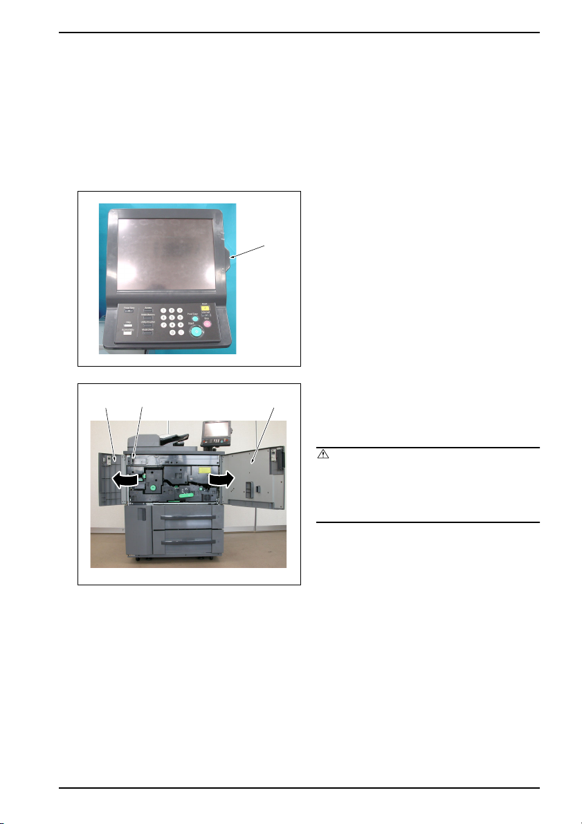
2.
Front door
/Left
Main power switch
Front door
/Right
Open the front door /Right and the front door /
Left, and then turn OFF the main power switch.
3.
Unplug the power cord from the wall outlet.
1050fs2001y
Caution:
• When conducting the replacement opera-
tions, be sure to turn OFF the main power
switch and the sub power switch and then
unplug the power cord from the wall outlet.
7
Page 11
1. Main body: pick-up roller assembly/separation roller assembly replacement instructions
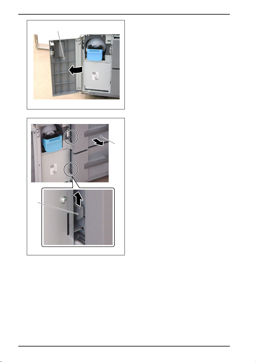
4.
Open the toner supply door.
Toner supply door
1050fs2063z
5.
Raise up the tray lock lever lightly and pull out the
tray.
Tray
Tray
lock
lever
1050fs2700c
8
Page 12
Pick-up
roller
1. Main body: pick-up roller assembly/separation roller assembly replacement instructions
6.
Rotate the pick-up roller in the arrow-marked
direction (counterclockwise as seen from the
front) and place the coupling in the longitudinal
direction.
NOTE
• The rotation of the pick-up roller is restricted
only to the arrow-marked direction (counter-
clockwise). It does not rotate in the reverse
direction (clockwise). So, be sure not to turn it
in this direction forcibly.
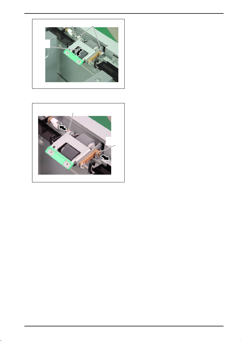
7.
Remove the 2 C-clips.
8.
Remove the bearing /Front.
9.
Slide the bearing /Rear to the rear side.
Bearing /Rear
C-clipCoupling
1050fs2701c
Bearing
/Front
1050fs2702z
9
Page 13
1. Main body: pick-up roller assembly/separation roller assembly replacement instructions
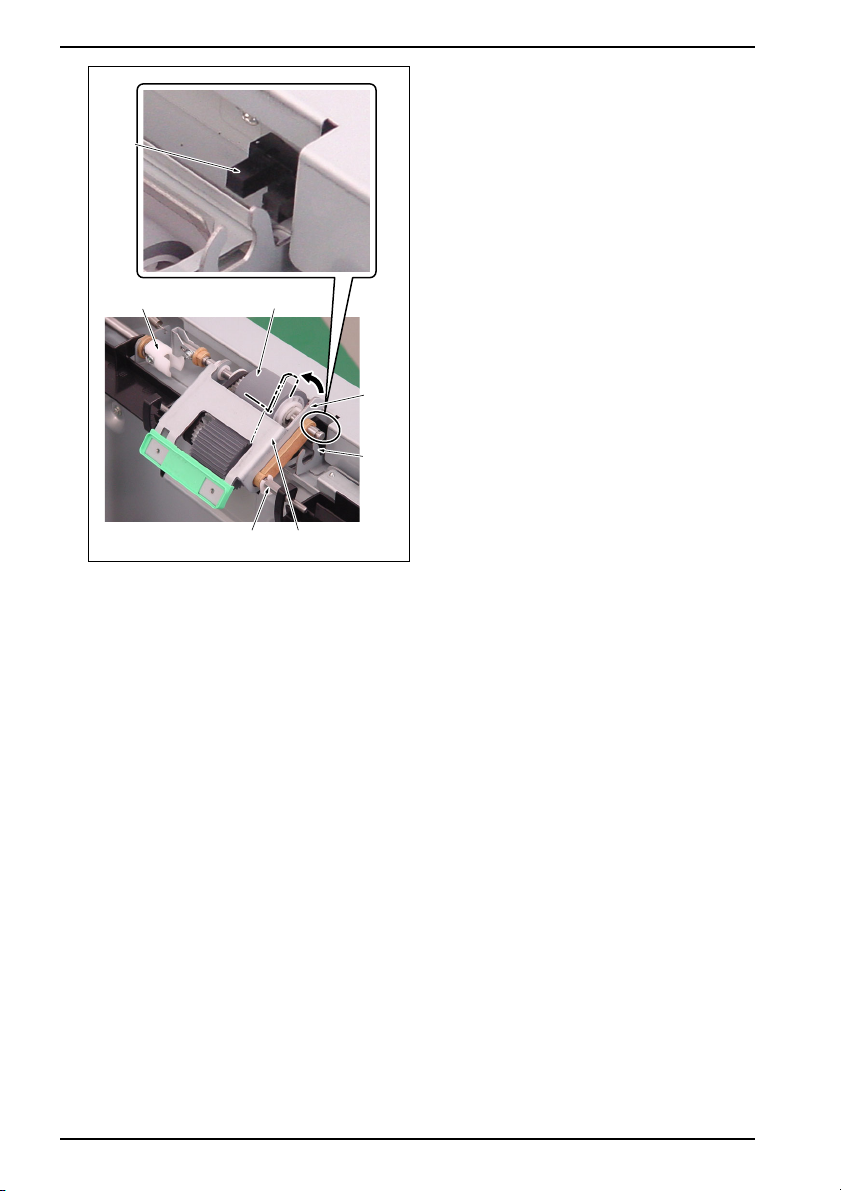
10.
Hold the pick-up roller assembly by hand and lift
the paper feed roller up to tilt while rotating it
around the pick-up roller shaft, and then remove
Sensor
it from the notch of the bearing and the joint.
NOTE
• When removing the pick-up roller, be careful
not to damage the sensor with the metal
frame.
Joint Paper feed roller
Metal
frame
Notch
Pick-up roller shaft
Pick-up roller assembly
1050fs2703c
10
Page 14

1. Main body: pick-up roller assembly/separation roller assembly replacement instructions
Pick-up roller assembly
Arm
Pick-up roller shaft
Pick-up
roller
assembly
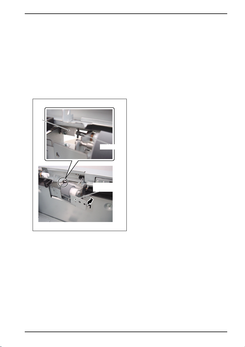
11.
Remove the pick-up roller shaft from the arm of
the paper feed guide plate and then remove the
pick-up roller assembly.
Entrance guide plate
Screw
1050fs2704c
1050fs2705c
11
12.
Remove the 2 screws and then remove the
entrance guide plate.
Page 15

1. Main body: pick-up roller assembly/separation roller assembly replacement instructions
13.
Separation roller assembly
Remove the 2 screws and release the fixing of
the separation roller assembly.
Joint
Screw
1050fs2706c
Coupling pin
Separation roller
assembly
1050fs2707c
14.
After pulling out the front side of the separation
roller assembly, remove the coupling pin in the
rear from the joint.
15.
When installing a new replacement part, see "(3)
Procedure for reinstallation" (on the next page).
12
Page 16
1. Main body: pick-up roller assembly/separation roller assembly replacement instructions
(3) Procedure for reinstallation
NOTE
• The method for replacing the pick-up roller assembly/separation roller assembly is the same for
the tray /1 and the tray /2. The explanation here is given of the tray /1.
• After completion of the installation, rotate the pick-up roller in the direction of the paper feed
(counterclockwise as seen from the front) to check to see if the paper feed roller, the belt and the
coupling section rotate smoothly. The rotation of the pick-up roller is restricted only to the direc-
tion of the paper feed (counterclockwise as seen from the front) and be absolutely sure not to turn
it clockwise.
• Be sure to take note that the direction of the pick-up roller assembly is different for the main body
and the PF-701.
1.
Insert the new separation roller assembly askew
and engage the coupling pin with the joint.
Joint
Coupling pin
Separation roller
assembly
1050fs2707z
NOTE
• Be sure to engage the coupling pin with the
joint.
13
Page 17

1. Main body: pick-up roller assembly/separation roller assembly replacement instructions
2.
Separation roller assembly
Install the separation roller assembly with the 2
screws.
NOTE
• When installing the separation roller assem-
bly, be sure to screw it while pressing it down.
Screw
Entrance guide plate
Screw
1050fs2706z
1050fs2705z
3.
Attach the entrance guide plate with the 2
screws.
14
Page 18
Pick-up roller assembly
Paper feed
guide plate
arm
Sensor
1. Main body: pick-up roller assembly/separation roller assembly replacement instructions
4.
Insert the pick-up roller shaft of the new pick-up
roller assembly into the paper feed guide plate
arm.
Pick-up roller
shaft
1050fs2704z
5.
With the pick-up roller shaft being used as a ful-
crum, rotate the pick-up roller assembly and
insert the shaft and the coupling of the paper
feed roller into the notch of the bearing and the
joint respectively.
Coupling
Joint
Pick-up roller shaft
Paper feed roller
Pick-up roller assembly
Metal
frame
Shaft
Notch
1050fs2703z
NOTE
• Be sure to engage the coupling of the paper
feed roller with the joint.
• When installing the pick-up roller assembly,
be careful not to damage the sensor with the
metal frame.
15
Page 19

1. Main body: pick-up roller assembly/separation roller assembly replacement instructions
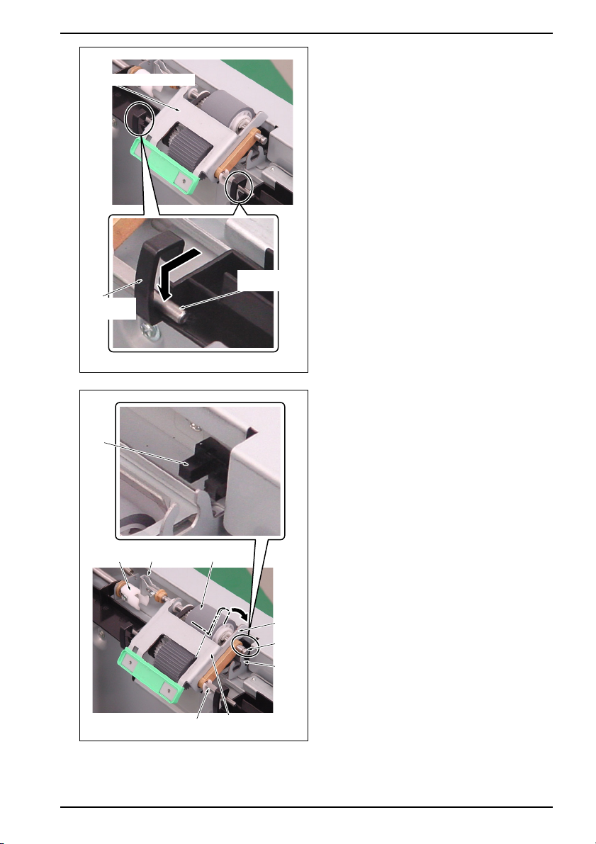
6.
Insert the bearing /Rear into the notch /1 of the
metal frame while pressing down a little the metal
Bearing /Rear
Notch /1
frame of the pick-up roller assembly.
7.
Insert the bearing /Front into the notch /2 of the
metal frame while pressing down a little the metal
frame of the pick-up roller assembly.
Bearing /Rear
Metal
frame
Bearing
/Front
Pick-up
roller
C-clips
Notch /2
1050fs2702y
1050fs2701z
8.
Attach the 2 C-clips.
9.
Hold the pick-up roller lightly with your hands and
rotate it counterclockwise as seen from the front.
And then check the paper feed roller, the belt and
the coupling section to see if they rotate
smoothly.
NOTE
• The rotation of the pick-up roller is restricted
only to the arrow-marked direction (counter-
clockwise). It does not rotate in the reverse
direction (clockwise). So, be sure not to turn it
in this direction forcibly.
16
Page 20

1. Main body: pick-up roller assembly/separation roller assembly replacement instructions
10.
Put the tray back to its original position.
Tray
1050fs2700z
11.
Close the toner supply door.
Toner supply door
1050fs2063y
Front door
/Left
Main power switch
Front door
/Right
1050fs2001x
17
12.
Plug the power cord into the wall outlet.
13.
Turn ON the main power switch and close the
front door /Left and the front door /Right.
Page 21

1. Main body: pick-up roller assembly/separation roller assembly replacement instructions
14.
Turn ON the sub power switch.
Sub
power
switch
1050fs5012z
18
Page 22

2. Main body:
Fusing section
Fusing unit
REPLACEMENT INSTRUCTIONS
19
2004.10
Ver. 1.0
Page 23

2. Main body: fusing section replacement instructions
(1) Purpose
To return to the normal operation as soon as possible when a decrease in the fusibility is found due to the
deterioration of the fusing unit.
(2) Procedure for removal
1.
Turn OFF the sub power switch.
Sub
power
switch
1050fs5012z
2.
Front door
/Left
Main power switch
Front door
/Right
1050fs2001y
Open the front door /Right and the front door /
Left, and then turn OFF the main power switch.
3.
Unplug the power cord from the wall outlet.
Caution:
• When conducting the replacement opera-
tions, be sure to turn OFF the main power
switch and the sub power switch and then
unplug the power cord from the wall outlet.
• Since the fusing unit is very hot immediately
after each of the power switches is turned
OFF, you may get burnt. Be sure to conduct
the operation after the fusing unit cools down
sufficiently.
20
Page 24

2. Main body: fusing section replacement instructions
4.
Bring down the pull-out lever to the right side
while pressing with a driver the lock release lever
in the arrow-marked direction, and pull out the
ADU.
ADU
Lock release lever
Paper
reverse
/exit
section
Fusing paper exit section
Pull-out lever
1050fs2001z
1050fs2002c
Screws
Fusing
cover
5.
Open the paper reverse/exit section.
6.
Open the fusing paper exit section.
7.
Remove the 2 screws and then remove the fus-
ing cover.
21
Page 25

2. Main body: fusing section replacement instructions
Lever assist plate Screw [1]
8.
Remove the screw [1] and then remove the lever
assist plate.
9.
Remove the screw [2] and release the fixing of
the fusing unit.
10.
Close the fusing paper exit section.
11.
Slide the fusing unit diagonally to the front, and
then raise the jam handling knob and the handle
with both hands to remove it.
12.
When installing a new replacement part, see "(3)
Procedure for reinstallation" (on the next page).
Fusing unit
Fusing
paper
exit
section
Jam handling knob
Handle
Screw [2]
1050fs2003z
22
Page 26

(3) Procedure for reinstallation
Reverse/
exit
section
Jam
handling
knob
Fusing unit Handle
Screw [1]
2. Main body: fusing section replacement instructions
1.
Check the reverse/exit section to see if it is open.
2.
Hold the jam handling release knob and the han-
dle with both hands and set the new fusing unit.
NOTE
• The position to which the fusing unit is set is
provided with a guide pin. Be sure to set the
guide pin to the concave portion at the bot-
tom of the fusing unit.
3.
With the fusing unit set to the reverse/exit sec-
tion, slide the fusing unit to the rear side until it
hits against the rear.
NOTE
• Be sure to slide the fusing unit until it hits
against the rear.
4.
With the fusing unit pressed against the rear side,
fix it with the screw [1].
5.
Attach the lever assist plate with the screw [2].
Fusing paper
exit section
Shaft
Hole
Screw [2]Lever assist plate
1050fs2003y
1050fs2004z
Driver
23
6.
Open the fusing paper exit section.
7.
With a driver inserted into the hole of the shaft,
rotate the shaft counterclockwise (in the arrow-
marked direction) until it cannot turn any more to
give pressure upon the fusing roller.
Page 27

2. Main body: fusing section replacement instructions
Reverse/
exit
section
Screw
Fusing
cover
8.
Install the fusing cover and fasten it with the 2
screws.
9.
Close the fusing paper exit section.
10.
Close the reverse/exit section.
Fusing paper exit section
Front door
/Left
Main power switch
Pull-out leverADU
Front door
/Right
1050fs2002z
1050fs2001w
11.
Push in the ADU while holding the pull-out lever
by hand, and then lock the pull-out lever.
NOTE
• When the ADU is brought back to its original
position, be sure to lock the pull-out lever.
12.
Plug the power cord into the wall outlet.
13.
Turn ON the main power switch and close the
front door /Left and the front door /Right.
1050fs2001x
24
Page 28

Sub
power
switch
1050fs5012z
2. Main body: fusing section replacement instructions
14.
Turn ON the sub power switch.
25
Page 29

3 Main body:
Cleaning web
Cleaning web
REPLACEMENT INSTRUCTIONS
26
2004.10
Ver. 1.0
Page 30

3. Main body: cleaning web replacement instructions
(1) Purpose
To return to the normal operation as soon as possible after completion of the wind-up of the cleaning web.
(2) Procedure for removal
1.
Turn OFF the sub power switch.
Sub
power
switch
1050fs5012z
2.
Front door
/Left
Main power switch
Front door
/Right
1050fs2001y
Open the front door /Right and the front door /
Left, and then turn OFF the main power switch.
3.
Unplug the power cord from the wall outlet.
Caution:
• When conducting the replacement opera-
tions, be sure to turn OFF the main power
switch and the sub power switch and then
unplug the power cord from the wall outlet.
• The cleaning web is installed at the fusing
unit. Since the fusing unit is very hot immedi-
ately after each of the power switches is
turned OFF, you may get burnt. Be sure to
conduct the operation after the fusing unit
cools down sufficiently.
27
Page 31

3. Main body: cleaning web replacement instructions
4.
Bring down the pull-out lever to the right side
while pressing with a driver the lock release lever
in the arrow-marked direction, and pull out the
ADU.
ADU
Screw
Lock release lever
Pull-out lever
1050fs2001z
Web cover
1050fs2163c
5.
Remove the 2 screws and then remove the web
cover.
28
Page 32

Cleaning
web
Couplings
1050fs2164c
3. Main body: cleaning web replacement instructions
6.
Release the couplings provided at the 2 places in
the arrow-marked direction and remove the used
cleaning web.
7.
When installing a new replacement part, see "(3)
Procedure for reinstallation" (on the next page).
29
Page 33

3. Main body: cleaning web replacement instructions
(3) Procedure for reinstallation
Driven couplings /Rear
Detent
Shaft on the unused side
Wind-up shaft
Cleaning
web
Notch
1.
Set the shaft on the unused side of the new
cleaning web to the driven couplings /Rear and /
Front.
NOTE
• Be sure to set each of the detent on the driven
couplings to the notch of the wind-up shaft.
When the web is installed in the wrong direc-
tion, it does not coincide with the notch.
2.
Hold either side of the wind-up shaft of the new
cleaning web with both hands, and take up the
new cleaning web until the blue line disappears.
NOTE
• The performance of the new cleaning web is
guaranteed from the position in which the
blue line disappears. Be sure to take up the
cleaning web up to this position.
Blue
line
Notch
Either side
Shaft on the unused side Detent
Driven
couplings
/Front
1050fs2165c
30
Page 34

Cleaning
web
Wind-up
shaft
Wind-up coupling /Front
Notch
Detent
3. Main body: cleaning web replacement instructions
3.
Install the wind-up shaft of the new cleaning web
to the wind-up couplings /Front and /Rear.
NOTE
• Be sure to set each of the detent on the driven
coupling to the notch of the wind-up shaft.
Wind-up
coupling /Rear
Screw
Detent
Notch
Wind-up shaft
Web cover
1050fs2166c
1050fs2163z
31
4.
Install the web cover with the 2 screws.
Page 35

3. Main body: cleaning web replacement instructions
Pull-out leverADU
1050fs2001w
Front door
/Left
Main power switch
Front door
/Right
5.
Push in the ADU while holding the pull-out lever
by hand, and then lock the pull-out lever.
NOTE
• When the ADU is brought back to its original
position, be sure to lock the pull-out lever.
6.
Plug the power cord into the wall outlet.
7.
Turn ON the main power switch and close the
front door /Left and the front door /Right.
1050fs2001x
Sub
power
switch
1050fs5012z
32
8.
Turn ON the sub power switch.
Page 36

4. Main body:
Transfer/separation
Transfer/separation
charger unit
charger unit
REPLACEMENT INSTRUCTIONS
33
2004.10
Ver. 1.0
Page 37

4. Main body: transfer/separation charger unit replacement instructions
(1) Purpose
To return to the normal operation as soon as possible when a decrease in the transfer or separation perfor-
mance is found due to the deterioration of the transfer/separation charger unit.
(2) Procedure for removal
1.
Turn OFF the sub power switch.
Sub
power
switch
1050fs5012z
2.
Front door
/Left
Main power switch
Front door
/Right
Open the front door /Right and the front door /
Left, and then turn OFF the main power switch.
3.
Unplug the power cord from the wall outlet.
Caution:
• When conducting the replacement opera-
tions, be sure to turn OFF the main power
switch and the sub power switch and then
unplug the power cord from the wall outlet.
1050fs2001y
34
Page 38

4. Main body: transfer/separation charger unit replacement instructions
4.
Bring down the pull-out lever to the right side
while pressing with a driver the lock release lever
in the arrow-marked direction, and pull out the
ADU.
ADU
Lock release lever
Screw
Pull-out lever
1050fs2001z
Connector cover
1050fs2019c
5.
Remove the screw and then remove the connec-
tor cover.
35
Page 39

4. Main body: transfer/separation charger unit replacement instructions
6.
Screw
Block
Transfer
/separation unit
Disconnect the connector [1].
NOTE
• When the transfer/separation charger unit is
equipped with a transfer assist sheet other
than the standard part, be sure to replace also
the connector [2].
• The guide plate has been adjusted in high
precision before being assembled. So, when
removing the transfer/separation charger, be
sure to avoid holding the guide plate to pull it
up but hold the blocks provided at both sides.
7.
Loosen the 2 screws and remove the transfer/
separation unit.
8.
When installing a new replacement part, see "(3)
Procedure for reinstallation" (on the next page).
Block
Connector [1] Connector [2]
Screw
1050fs2020c
36
Page 40

(3) Procedure for reinstallation
Screw
4. Main body: transfer/separation charger unit replacement instructions
1.
Install the new transfer/separation charger unit
and fasten it with the 2 screws.
2.
Connect the connector [1].
NOTE
• When the transfer/separation charger unit is
equipped with a transfer assist sheet other
than the standard part, be sure to replace also
the connector [2].
Transfer
/separation unit
Connector [1] Connector [2]
Screw
Screw
1050fs2020z
Connector cover
1050fs2019z
37
3.
Attach the connector cover with the screw.
Page 41

4. Main body: transfer/separation charger unit replacement instructions
4.
Push in the ADU while holding the pull-out lever
by hand, and then lock the pull-out lever.
NOTE
• When the ADU is brought back to its original
position, be sure to lock the pull-out lever.
Pull-out leverADU
1050fs2001w
5.
Front door
/Left
Main power switch
Front door
/Right
Plug the power cord into the wall outlet.
6.
Turn ON the main power switch and close the
front door /Left and the front door /Right.
1050fs2001x
Sub
power
switch
1050fs5012z
38
7.
Turn ON the sub power switch.
Page 42

5. DF-603:
Pick-up roller unit/
Pick-up roller unit/
separation roller unit
separation roller unit
REPLACEMENT INSTRUCTIONS
DF-603
39
2004.10
Ver. 1.0
Page 43

5. DF-603: pick-up roller unit/separation roller unit replacement instructions
(1) Purpose
To return to the normal operation as soon as possible when a decrease in the paper feedability is found due
to the deterioration of the pick-up roller or separation roller.
(2) Procedure for the removal of the pick-up roller unit
1.
Turn OFF the sub power switch.
Sub
power
switch
1050fs5012z
2.
Front door
/Left
Main power switch
Front door
/Right
Open the front door /Right and the front door /
Left, and then turn OFF the main power switch.
3.
Unplug the power cord from the wall outlet.
Caution:
• When conducting the replacement opera-
tions, be sure to turn OFF the main power
switch and the sub power switch and then
unplug the power cord from the wall outlet.
Screw
Open/close cover
1050fs2001y
Sensor
cover
df603fs2001c
40
4.
Open the open/close cover.
5.
Remove the 3 screws and then remove the sen-
sor cover in the arrow-marked direction.
Page 44

C-ring /2
Bearing
5. DF-603: pick-up roller unit/separation roller unit replacement instructions
6.
Remove the spring of the pick-up roller unit.
7.
Coupling
Spring
Pick-up
roller unit
One-way
clutch
C-ring /1
df603fs2002c
Remove the C-rings /1 and /2, and slide the
bearing and the one-way clutch to the outside
respectively.
8.
Slide the pick-up roller unit once to the front side,
and release it from the coupling to remove it
upward.
9.
When installing a new replacement part, see "(3)
Procedure for the reinstallation of the pick-up
roller unit" (on the next page).
41
Page 45

5. DF-603: pick-up roller unit/separation roller unit replacement instructions
(3) Procedure for the reinstallation of the pick-up roller unit
1.
Check the shaft of the new pick-up roller unit to
see if it is provided with the bearing.
2.
Insert the shaft of the new pick-up roller unit into
the notches /1 and /2 of the bearing.
3.
Slide the shaft of the new pick-up roller unit to
the rear side and insert it into the coupling.
NOTE
• Be sure to fit the shaft of the pick-up roller
unit in the coupling.
4.
Slide the one-way clutch to the inside and set it
to the notch /1 of the bearing.
5.
Slide the bearing to the inside and set it to the
notch /2 of the bearing.
6.
Attach the C-rings /1 and /2.
7.
Attach the spring.
NOTE
• Check to see if the bending section at the
edge on the original feed tray side of the pick-
up roller unit is above the folding section of
the stay. When it is below the bending sec-
tion, the original cannot be fed correctly.
C-ring /2
Bearing
Notch /1
Coupling
Notch /2
Spring
Pick-up
roller unit
One-way
clutch
C-ring /1
df603fs2002z
Bending
section
at the edge
Folding
section
df603fs2004c
42
Page 46

Screw
5. DF-603: pick-up roller unit/separation roller unit replacement instructions
8.
Install the sensor cover with the 3 screws.
9.
Close the open/close cover.
Sensor
cover
Open/close cover
Front door
/Left
Main power switch
df603fs2001z
Front door
/Right
1050fs2001x
Sub
power
switch
10.
Plug the power cord into the wall outlet.
11.
Turn ON the main power switch and close the
front door /Left and the front door /Right.
12.
Turn ON the sub power switch.
1050fs5012z
43
Page 47

5. DF-603: pick-up roller unit/separation roller unit replacement instructions
(4) Procedure for the removal of the separation roller unit
1.
Remove the pick-up roller unit. (See "(2) Proce-
dure for the removal of the pick-up roller unit" (on
page 1))
2.
Remove the 2 screws and then remove the auxil-
iary roller assembly.
3.
Remove the C-ring and then remove the gear.
4.
Slide the 2 bearings to the outside and remove
the separation roller unit.
5.
When installing a new replacement part, see "(5)
Procedure for the reinstallation of the separation
roller unit" (on the next page).
Screw
C-ring
Auxiliary
roller
assembly
df603fs2005c
Gear
Separation
roller unit
Bearing
df603fs2006c
44
Page 48

5. DF-603: pick-up roller unit/separation roller unit replacement instructions
(5) Procedure for the reinstallation of the separation roller unit
1.
Set the new separation roller unit in the notch of
C-ring
Gear
Separation
roller unit
the bearing.
2.
Fit the 2 bearings in the respective notches of the
bearings.
3.
Install the gear.
4.
Attach the C-ring.
Bearing
Screw
Notch
df603fs2006z
Auxiliary
roller
assembly
df603fs2005z
5.
Install the auxiliary roller assembly with the 2
screws.
6.
For subsequent steps of the installation proce-
dure, see "(3) Procedure for the reinstallation of
the pick-up roller unit" (on page 41).
45
Page 49

6. PF-701:
Pick-up roller unit/
Pick-up roller unit/
separation roller unit
separation roller unit
REPLACEMENT INSTRUCTIONS
PF-701
46
2004.10
Ver. 1.0
Page 50

6. PF-701: pick-up roller unit/separation roller unit replacement instructions
(1) Purpose
To return to the normal operation as soon as possible when a decrease in the paper feedability is found due
to the deterioration of the pick-up roller or separation roller.
(2) Procedure for removal
NOTE
• The removing/reinstalling methods of the pick-up roller unit and the separation roller unit are the
same for all of the trays /3, /4 and /5. The explanation here is made of the examples of the tray /3.
1.
Turn OFF the sub power switch.
Sub
power
switch
1050fs5012z
2.
Front door
/Left
Main power switch
Front door
/Right
Open the front door /Right and the front door /
Left, and then turn OFF the main power switch.
3.
Unplug the power cord from the wall outlet.
1050fs2001y
Caution:
• When conducting the replacement opera-
tions, be sure to turn OFF the main power
switch and the sub power switch and then
unplug the power cord from the wall outlet.
47
Page 51

6. PF-701: pick-up roller unit/separation roller unit replacement instructions
4.
Open the front door.
5.
Insert a driver into the hole and pull out the tray
while lifting up the tray lock lever a little.
Hole
Tray
lock
lever
Tray
Front
door
pf701fs2001c
C-clip
Coupling
Pick-up
roller
pf701fs2002c
6.
Rotate the pick-up roller in the arrow-marked
direction (clockwise as seen from the front side)
and bring the coupling to the lengthwise direc-
tion.
NOTE
• The rotation of the pick-up roller is restricted
only to the arrow-marked direction (clock-
wise). It will not rotate in the reverse direction
(counterclockwise) and be careful not to
rotate it in the reverse direction forcibly.
7.
Remove the 2 C-clips.
48
Page 52

Bearing
/Front
Paper feed
roller
Metal frame
Notch
Joint
6. PF-701: pick-up roller unit/separation roller unit replacement instructions
8.
Remove the bearing /Front.
9.
Move the bearing /Rear to the rear side.
Bearing
/Rear
pf701fs2003z
10.
Hold the pick-up roller unit by hand and lift and
tilt the paper feed roller so that it rotates on the
pick-up roller shaft to remove it from the notch of
Pick-up
roller unit
Pick-up
roller shaft
the bearing and the joint.
NOTE
• When removing the pick-up roller unit, be
careful not to damage the sensor with the
metal frame.
Sensor
pf701fs2004c
49
Page 53

6. PF-701: pick-up roller unit/separation roller unit replacement instructions
11.
Remove the pick-up roller shaft from the arm of
Pick-up
roller unit
the paper feed guide plate and then remove the
pick-up roller unit.
Arm
Pick-up
Pick-up roller unit
roller
shaft
Screw
Entrance guide plate
pf701fs2005c
pf701fs2006c
50
12.
Remove the 2 screws and then remove the
entrance guide plate.
Page 54

Coupling pin
Separation
roller unit
Screw
Joint
6. PF-701: pick-up roller unit/separation roller unit replacement instructions
13.
Remove the 2 screws and release the fixing of
the separation roller unit.
Separation
roller unit
pf701fs2007c
14.
Pull out the front side of the separation roller unit
in the arrow-marked direction, and then remove
the coupling pin in the rear from the joint.
15.
When installing a new replacement part, see "(3)
Procedure for reinstallation" (on the next page).
pf701fs2008y
51
Page 55

6. PF-701: pick-up roller unit/separation roller unit replacement instructions
(3) Procedure for reinstallation
NOTE
• The removing/reinstalling methods of the pick-up roller unit and the separation roller unit are the
same for all of the trays /3, /4 and /5. The explanation here is made of the examples of the tray /3.
• After completion of installation, be sure to rotate the pick-up roller in the paper feed direction
(clockwise as seen from the front side) to check to see if the paper feed roller and the belt rotate
smoothly. The rotation is restricted only to the paper feed direction (clockwise as seen from the
front side) and be careful not to rotate it counterclockwise.
• Be careful that the pick-up roller unit and the separation roller unit are different in the direction for
the main body and the PF-701.
1.
Coupling pin
Separation
roller unit
Joint
Insert the new separation roller unit askew and
engage the coupling pin with the joint.
NOTE
• Be sure to engage the coupling pin with the
joint.
• For a separation roller unit, there are two
types and their use is decided according to
the type of trays. The type (1) is used for the
trays /3 and /5 and the type (2) that has more
gears is used for the tray /4.
(2) For the tray /4(1) For the trays /3 and /5
pf701fs2008z
52
Page 56

Screw
Screw
6. PF-701: pick-up roller unit/separation roller unit replacement instructions
2.
Install the separation roller unit with the 2 screws.
NOTE
• When installing the separation roller unit, be
sure to screw it while pressing it down.
Separation
roller unit
pf701fs2007z
3.
Install the entrance guide plate with the 2 screws.
Entrance guide plate
pf701fs2006z
Pick-up
roller unit
Arm
Pick-up
roller shaft
pf701fs2005z
53
4.
Insert the pick-up roller shaft of the new pick-up
roller unit into the paper feed guide plate arm.
Page 57

6. PF-701: pick-up roller unit/separation roller unit replacement instructions
5.
Notch, bearing
Paper feed
roller
Metal frame
Coupling, joint
Pick-up
roller unit
Pick-up
roller shaft
Sensor
pf701fs2004z
Rotate the pick-up roller unit with the shaft of the
pick-up roller used as a fulcrum and insert the
shaft and the coupling of the paper feed roller
into the notch of the bearing and the joint
respectively.
NOTE
• Be sure to engage the coupling of the paper
feed roller with the joint.
• When installing the pick-up roller unit, be
careful not to damage the sensor with the
metal frame.
54
Page 58

Notch /2
Bearing
/Front
6. PF-701: pick-up roller unit/separation roller unit replacement instructions
6.
Put the bearing /Rear in the notch /1 of the metal
Bearing
/Rear
Bearing
/Rear
frame while pressing down a little the metal frame
of the pick-up roller unit.
7.
Put the bearing /Front in the notch /2 of the metal
frame while pressing down a little the metal frame
of the pick-up roller unit.
Notch /1
Metal
frame
C-clip
pf701fs2003y
Pick-up
roller
pf701fs2002z
8.
Attach the 2 C-clips.
9.
Hold the pick-up roller lightly and rotate it clock-
wise as seen from the front. And then check the
paper feed roller, the belt, and the coupling sec-
tion to see if they rotate smoothly.
NOTE
• The rotation of the pick-up roller is limited
only in the arrow-marked direction (clock-
wise) and it does not rotate in the reverse
direction (counterclockwise). Be sure to avoid
rotating it in the reverse direction forcibly.
55
Page 59

6. PF-701: pick-up roller unit/separation roller unit replacement instructions
10.
Put the tray /4 back to its original position.
11.
Close the front door.
12.
Plug the power cord into the wall outlet.
13.
Turn ON the main power switch and close the
front door /Left and the front door /Right.
Front door
/Left
Main power switch
Tray /4
Front
door
pf701fs2001z
Front door
/Right
1050fs2001x
Sub
power
switch
1050fs5012z
56
14.
Turn ON the sub power switch.
Page 60

 Loading...