


ORIGINAL INSTRUCTIONS - according to Directive 2006/42/EC, Annex I 1.7.4.1
OPERATOR’S MANUAL
Z 8805 T
Tedder
Part number 81PIGB-188x
1st edition English
February 2018


PIGB-188X-03 Z 8805 T 0218
3
FOREWORD
DEAR CUSTOMER!
We appreciate the confidence you have shown to our company by investing in a
KONGSKILDE product and congratulate you on your new purchase. Of course, it is
our wish that you will experience complete satisfaction with the purchase investment.
This instruction manual contains information about correct and safe use of the
machine.
When buying the machine you will receive information about use, adjustment and
maintenance.
However, this first introduction cannot replace a more thorough knowledge of the
different tasks, functions and correct technical use of the machine.
Therefore you should read this instruction manual very carefully before using
the machine. Pay special attention to the safety instructions.
This instruction manual is made so that the information is mentioned in the order you
will need it, i.e. from the necessary operation conditions to use and maintenance. In
addition, there are illustrations to accompany the text.
"Right" and "Left" are defined from a position behind the machine facing the direction
of travel.
All the information, illustrations and technical specifications in this instruction manual
describe the latest version at the time of publication.
Kongskilde Industries A/S reserves the right to make changes or improvements in the
design or construction of any part without incurring the obligations to install such
improvements on any unit previously delivered.

PIGB-188X-03 Z 8805 T 0218
4
FOREWORD ....................................................................................................................... 3
1. IN GENERAL .................................................................................................................. 6
INTENDED USE ................................................................................................. 6
FORESEEABLE MISUSE ................................................................................... 7
General safety instructions ..................................................................... 7
TECHNICAL DATA ............................................................................................. 8
Manufacturer’s address .......................................................................... 8
Certificates ............................................................................................. 8
Marking of the machine ................................ ................................ .......... 8
General technical data ......................................................................... 10
2. SAFETY ........................................................................................................................ 11
MARKING OF SAFETY INSTRUCTIONS IN THE INSTRUCTION
MANUAL ........................................................................................................... 11
SAFETY RULES AND ACCIDENT PREVENTION ........................................... 12
Power take-off ...................................................................................... 14
Tyres .................................................................................................... 15
Working near high-voltage lines ........................................................... 15
Maintenance ........................................................................................ 16
Placement of reference signs on the machine ..................................... 18
3. MOUNTING OF THE MACHINE AFTER DELIVERY.................................................... 20
CONNECTION OF PTO SHAFT....................................................................... 24
ADJUSTMENT OF PTO DRIVE SHAFT ........................................................... 25
MOUNTING OF OPTIONAL EQUIPMENT ....................................................... 26
Support wheel ...................................................................................... 26
Anti-wrapping plate .............................................................................. 27
Night swath gearbox ............................................................................ 27
FUNCTIONAL TEST ......................................................................................... 28
4. MOUNTING OF THE TEDDER / PREPARATION ........................................................ 29
SPECIAL INSTRUCTIONS ............................................................................... 29
PREPARATION OF TRACTOR ........................................................................ 30
3-point suspension on the tractor ......................................................... 30
Placement of cord ................................................................................ 31
Hydraulic system (restriction) ............................................................... 31
Electric system ..................................................................................... 31
CONNECTION OF THE ROTARY TEDDER TO THE TRACTOR.................... 31
Connection to the link arms and top link of the tractor ......................... 31
Hydraulic connection ............................................................................ 33
Connection of lighting equipment ......................................................... 33
Connection of PTO shaft ...................................................................... 34
TRANSPORT ON PUBLIC ROADS .................................................................. 34
5. HANDLING OF THE TEDDER DURING WORKING .................................................... 35
CONVERSION OF THE TEDDER FROM TRANSPORT TO WORKING
POSITION ........................................................................................................ 35

PIGB-188X-03 Z 8805 T 0218
5
The stop valve in the centre of the machine ......................................... 35
Unfolding the machine in working position ........................................... 36
STARTING THE ROTOR ................................................................................. 36
POSITION WHEN DRIVING ON HEADLANDS ............................................... 37
SPREADING FROM FENCE ............................................................................ 38
CONVERSION OF THE TEDDER FROM WORKING TO TRANSPORT
POSITION ........................................................................................................ 40
Folding to transport position ................................................................. 40
Blocking of the hydraulics .................................................................... 42
SWIVELLING OF TRANSPORT AXLE ............................................................. 43
FOLDING OF SIDE ARMS ............................................................................... 44
DISCONNECTION OF THE MACHINE ............................................................ 45
6. BASIC ADJUSTMENT OF THE TEDDER .................................................................... 47
ADJUSTMENT OF WORKING DEPTH ............................................................ 47
ADJUSTMENT OF SPREADING ANGLE ........................................................ 48
WORKING SPEED AND NUMBER OF REVOLUTIONS ................................. 50
Driving speed and number of revolutions ............................................. 50
Spreading of mown swaths .................................................................. 50
Tedding ................................................................................................ 50
Spreading of swaths............................................................................. 51
Night swaths ........................................................................................ 51
7. SERVICE AND MAINTENANCE OF THE TEDDER ..................................................... 52
SAFETY RULES ............................................................................................... 52
GENERAL MAINTENANCE INSTRUCTIONS .................................................. 52
CLEANING OF THE MACHINE AND PREPARATION FOR WINTER
STORAGE ........................................................................................................ 52
Cleaning of the machine ...................................................................... 52
Placement of the machine in the open ................................................. 53
Winter storage ...................................................................................... 53
WHEELS .......................................................................................................... 53
Tyre pressure ....................................................................................... 53
PTO SHAFTS ................................................................................................... 54
Instructions regarding PTO shafts: ....................................................... 54
HYDRAULIC SYSTEM ..................................................................................... 54
8. MAINTENANCE - GREASE CHART ............................................................................ 55
PTO SHAFT ..................................................................................................... 55
GEARBOXES ................................................................................................... 56
GREASE SPOTS ON THE TEDDER ............................................................... 58
Joints .................................................................................................... 58
Oblong hole (guide).............................................................................. 59
Headstock ............................................................................................ 60
GREASE CHART OVERVIEW ......................................................................... 61
9. MACHINE DISPOSAL................................................................................................... 62
10. SUPPLEMENT ............................................................................................................ 63
11. WARRANTY ................................................................................................................ 65

1. IN GENERAL
PIGB-188X-03 Z 8805 T 0218
6
1. IN GENERAL
This instruction manual contains important information concerning operation,
maintenance and adjustment of the machine. Furthermore, all safety instructions are
mentioned and emphasized. Read the instruction manual carefully before using the
machine. The instruction manual should be accessible for the operator.
All safety instructions must be observed.
INTENDED USE
The rotary tedder is intended for tedding, swath spreading and producing night
swaths of straw crops on the ground.
The rotary tedder is solely constructed for usual work in agriculture.
The rotary tedder should only be connected to a tractor and driven by the PTO
of the tractor.
Any other use is regarded as not intended. The manufacturer is not
responsible for any damage resulting from such use; the user bears that risk.
Intended use also implies that the instructions and rules prescribed by the
manufacturer are observed.
The rotary tedder should only be used, maintained and repaired by persons
who, through relevant instructions and after reading the instruction manual, are
familiar with the machine and, in particular, are informed of possible dangers.
The following safety instructions as well as common rules concerning technical
safety, working practices and road safety must be observed altogether.
If changes are made on the machine and its construction without permission
from the manufacturer, the manufacturer cannot be held responsible for any
damage resulting from this.
Intended use also implies that the rules prescribed by the manufacturer
concerning operation, maintenance and service are observed.

1. IN GENERAL
PIGB-188X-03 Z 8805 T 0218
7
FORESEEABLE MISUSE
Sweeping of e.g. farmyards with the rake tines or brooms fastened to these is
not allowed. There is a risk that e.g. stones are thrown out from the working
area of the machine with danger of personal injury or damage to objects.
Any use beyond the intended use is regarded as foreseeable misuse.
GENERAL SAFETY INSTRUCTIONS
The following is a brief description of the measures, which should be a matter of
common knowledge to the operator.
1. Always disengage the PTO drive shaft, activate the parking brake and stop the
tractor engine before you
- lubricate the machine,
- clean the machine,
- maintain the machine.
- adjust the machine.
2. Always use the transport lock when transporting the machine.
3. Never work under a raised rotor unless it is secured by means of stop blocks or
other mechanical securing devices.
4. Always block the tractor wheels before working on the machine.
5. Never start the tractor until all persons are at a safe distance away from the
machine.
6. Make sure that all tools have been removed from the machine before starting
the tractor.
7. Make sure that all guards are intact and have been mounted correctly.
8. The clothes of the operator must be tight-fitting. During work never wear loose
clothes or have your hair hang down as it may be pulled in by the moving parts
of the machine.
9. Always drive with the statutory lights and safety marking during transport on
public roads and at night.
10. Do not stand near the machine while it is working.
11. When mounting the PTO drive shaft check that the number of rpm and the
direction of rotation of the tractor match those of the machine.
12. Before raising or lowering the machine, check that no persons are near the
machine or touching it.
13. Do not stand near the safety frames of the rake until all revolving parts have
stopped moving.
14. Never use the machine for other purposes than what it has been constructed
for.
15. Do not allow any children to be near when you are working with the machine.
16. Never stand between the tractor and the machine during connection and
disconnection.
1. IN GENERAL
PIGB-188X-03 Z 8805 T 0218
8
Fig. 1-1
P
R
1
3
-
0
3
1
4
TECHNICAL DATA
MANUFACTURER’S ADDRESS
Kongskilde Industries A/S
Lindeallé 7
DK-6400 Sønderborg – Denmark
Phone: +45-7412 5252
CERTIFICATES
-EC-Declaration of conformity (see page 64)
MARKING OF THE MACHINE
Fig. 1-1 The machine data is printed on the machine plate. The machine plate is placed in the
right-hand side in the direction of travelling behind the suspension at the frame.
The marking on the machine should neither be changed nor removed!
The information on the machine plate can be written below so that it is always at
hand.

1. IN GENERAL
PIGB-188X-03 Z 8805 T 0218
9
Machine type
Serial number
Manufacturing year
In case of service questions and when ordering spare parts, please state machine
type, serial number and manufacturing year so that the inquiry can be treated as
soon as possible.
Only use original KONGSKILDE spare parts. The manufacturer cannot be held
responsible for any damage resulting from the use of non-original spare parts.
1. IN GENERAL
PIGB-188X-03 Z 8805 T 0218
10
Technical data
Z 8805 T
Rotor diameter
1.50 m
Number of rotors
8
Double tines per tine arm:
6
Working width, max:
8.80 m
Minimum transport width:
2.95 m
Parking height
3.60 m
PTO rpm
540 rpm
Link arm category
II
Suspension type
Link arms
Power requirement
from 30/40 kW/HP
Wheel, rotor
16x6,50-8 (6PR)
18,5x8,50-8 (6PR)
Transport wheels
10.0/80-12
Oil outlets
1 double acting
Electricity (for extra lighting kit)
12 V
Equivalent sound pressure level
under 70 dB (A)
Weight, approx.
1510 kg
PR13-0315
Fig. 1-2
GENERAL TECHNICAL DATA
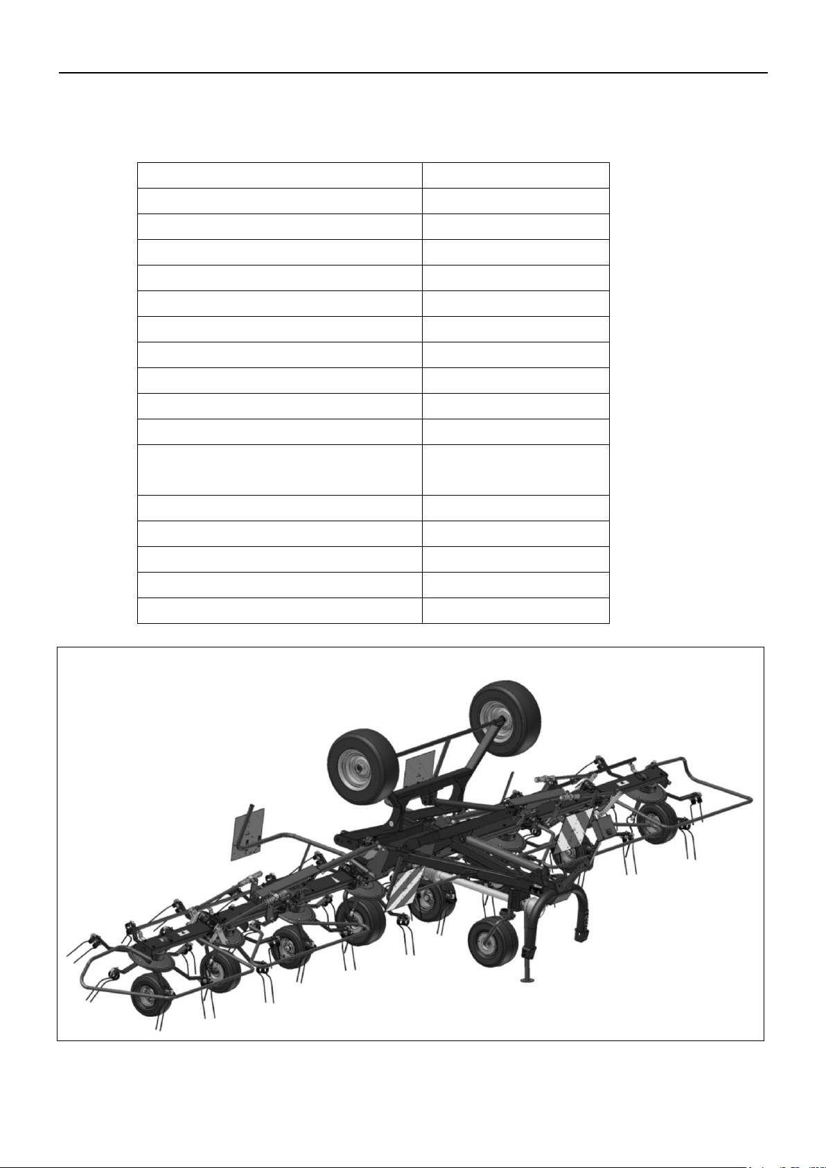
Fig. 1-2 Z 8805 T

2. SAFETY
PIGB-188X-03 Z 8805 T 0218
11
2. SAFETY
MARKING OF SAFETY INSTRUCTIONS IN THE
INSTRUCTION MANUAL
In this instruction manual this symbol is used with reference to personal safety
directly and indirectly through maintenance of the machine.
This symbol (safety marking according to DIN 4844-W9) is supplemented with the
following references:
General references are marked with this symbol:
Reference signs on the machine must be observed and kept in a readable condition.

2. SAFETY
PIGB-188X-03 Z 8805 T 0218
12
SAFETY RULES AND ACCIDENT PREVENTION
1. The safety instructions in this manual together with common rules concerning
safety and accident prevention must be observed!
2. The warning and reference signs provide important information on safe operation
and should be observed!
3. When driving on public roads the current safety rules must be observed!
4. Before working with the machine you should make yourself familiar with all
devices, operating elements and functions. During work this will be too late!
5. The clothes of the operator must be tight-fitting. Avoid loose clothes.
6. The machine should always be kept clean! Hereby you avoid danger of fire.
7. Always check the area around the machine before working, especially for
children! Make sure that your view is sufficient!
8. Never allow anybody to be on the machine during work and transport.
9. The machine must be connected as per instructions and should only be
secured/fastened at the prescribed devices!
10. During connection and disconnection the supports must be in the prescribed
positions!
11. Particular care is required during connection and disconnection of machines!
12. The limits for allowable axle load, total weight and transport dimensions must be
observed!
13. Transport equipment, e.g. lighting and warning kit as well as protection
equipment must be checked and fitted.
14. Operating parts (cords, chains, rods etc.) for remote control equipment must be
placed so that they do not cause unintended movements in transport and
working position.
15. For road transport the machine must be prepared and locked according to the
instructions of the manufacturer!
16. Never leave the tractor seat when driving!
17. Always adjust the driving speed to the conditions of the ground. When driving up
and down and across hillsides, sharp turns should be avoided!

2. SAFETY
PIGB-188X-03 Z 8805 T 0218
13
18. Driving, steering and braking capacity are influenced by mounted or trailed
implements and ballast weights. Therefore please be aware of sufficient steering
and braking capacity!
19. When turning pay attention to the overhang and oscillating weight of the
machine!
20. Only use the machine if all guards are mounted correctly!
21. Nobody should be allowed to stand in the working area!
22. Do not stand in the turning and swivel area of the machine!
23. Hydraulically foldable and pivotal frames should only be activated when there are
no persons in the swivel area!
24. Do not allow any person to stand under a raised machine when the machine is
not in locked position!
25. At remote-controlled (e.g. hydraulically controlled) units may be places where
there is danger of injury!
26. Lower the machine to the ground, stop the engine and remove the ignition key
before leaving the tractor!
27. Never stand between the tractor and the machine without securing the vehicle by
means of the hand brake and/or stop blocks!
28. Always stop the operation of the tedder when leaving the tractor seat.

2. SAFETY
PIGB-188X-03 Z 8805 T 0218
14
POWER TAKE-OFF
1. Only use the PTO drive shafts prescribed by the manufacturer!
2. The protection tube and cover of the PTO and the PTO guard – also on the
machine side – must be mounted and undamaged!
3. The tube overlap of the PTO shaft must be correct in transport and working
position!
4. Always stop the PTO and the tractor engine and remove the ignition key before
connecting or disconnecting the PTO drive shafts.
5. When using PTO shafts with overload or freewheel clutch which is not covered
by the protective devices of the tractor, the overload/freewheel clutches must be
placed on the machine side!
6. Always make sure that the PTO drive shaft has been mounted and secured
correctly!
7. The guard of the PTO shaft is secured with the chain!
8. Before starting the PTO check that the number of RPM of the tractor PTO
matches the number of RPM of the machine.
9. When using a travel speed controlled PTO, be aware that the number of rpm is
depending on the travel speed and that the direction of rotation will change when
backing!
10. Before starting the PTO check that there are no persons in the danger zone of
the machine!
11. Never connect the PTO if the engine has stopped!
12. When working with the PTO make sure that no persons stand near the rotating
PTO shaft.
13. Always stop the PTO if the deviation is too big or PTO is not used!
14. Caution! When the PTO has been stopped there will be a momentum! Do not get
too close to the machine. Do not carry out any work on the machine until it has
come to a complete stop!
15. Cleaning, greasing and adjustment of a PTO-driven machine or PTO shaft
should only take place when the PTO has been disconnected, the engine
stopped and the ignition key removed!
16. When the PTO shaft is disconnected from the tractor it must be fastened to the
suspension with the chain!
17. If the PTO shaft is damaged it must be repaired immediately before working with
the machine!

2. SAFETY
PIGB-188X-03 Z 8805 T 0218
15
Rated voltage
Safety distance from
overhead lines
KV
M
Up to 1
1
Over 1 to 110
2
Over 101 to 220
3
Over 220 to 380
4
TYRES
1. Before working on the tyres ensure that the machine is stable and cannot move
(by means of stop blocks)!
2. Mounting of wheels requires sufficient knowledge and correct mounting tools!
3. Repair of tyres and wheels should only be made by experts and with correct
mounting tools!
4. Check the tyre pressure regularly! Observe the prescribed tyre pressure!
WORKING NEAR HIGH-VOLTAGE LINES
1. Be very careful if working under or near high-voltage lines.
2. Make sure that the total height is as low as possible if working or transporting the
machine near high-voltage lines.
3. If driving under overhead lines the driver must contact the owner of the overhead
lines in order to get information on the rated voltage and minimum height of the
overhead lines.
4. The safety distances in the table must be observed.

2. SAFETY
PIGB-188X-03 Z 8805 T 0218
16
Ma
Ø
Class: 8.8
MA [Nm]
Class: 10.9
MA [Nm]
Class:12.9
MA [Nm]
M 8
25
33
40
M 10
48
65
80
M 12
80
120
135
M 12x1,25
90
125
146
M 14
135
180
215
M 14x1,5
145
190
230
M 16
200
280
325
M 16x1,5
215
295
350
M 18
270
380
440
M 20
400
550
650
M 20x1,5
430
615
720
M 24
640
900
1100
M 24x1,5
690
960
1175
M 30
1300
1800
2300
MAINTENANCE
In general:
When repairing or maintaining the machine it is especially important
to ensure correct personal safety. Therefore, always park the tractor
(if mounted) and the machine according to the GENERAL SAFETY
RULES, chapter 2, in the beginning of this instruction manual.
Screws and bolts on your new machine must be retightened after 5 hours of
operation. This also applies if repairs have been made.
Torque measurement MA (if nothing else has been stated).

2. SAFETY
PIGB-188X-03 Z 8805 T 0218
17
1. Maintenance, service, cleaning and repair must only take place when the PTO and
the engine have been stopped! - Remove the ignition key! - Apply the hand
brake of the tractor or secure the tedder so that it cannot move!
2. Screws and nuts must be checked regularly and re-tightened if necessary!
3. If maintenance is going to be made on a machine in raised position, always secure
it by means of appropriate supports!
4. Oil and grease are disposed of as prescribed!
5. Disconnect the power before working on the electric system!
6. If guards are exposed to wear they must be checked regularly and replaced in
time!
7. Before carrying out electric welding on tractor and mounted machine the cable for
alternator and battery must be dismounted.
8. Spare parts must at least correspond to the technical requirements prescribed by
the manufacturer! Original spare parts observe these requirements!

2. SAFETY
PIGB-188X-03 Z 8805 T 0218
18
PLACEMENT OF REFERENCE SIGNS ON THE MACHINE
The reference signs are warning of dangers of the machine. The safety references
must be observed at any time. Reference signs must be kept clean and in a readable
condition. Damaged or missing safety signs must be ordered from your dealer as
spare parts and must be placed at the correct positions!
1. Read the instruction manual and the safety instructions carefully before using
the machine, and observe the instructions!
2. Always stop the PTO and the tractor engine and remove the ignition key before
maintaining, repairing and servicing the machine!
3. Do not touch the machine until the rotating parts have come to a complete stop!
4. Keep a safe distance to the rotating parts of the machine! When the engine is
running, there is a risk of parts being thrown out.
5. Never move your hand into the danger zone as long as the parts can move!
This may cause serious injury and, at worst, result in death!
6. The hydraulic pressure must not exceed 210 bar.
7. The prescribed maximum number of rotations and direction.
Reference to the minimum overlap on the profile tubes and the minimum
distance in order not to bottom the shaft out.
8. The pressure tank is under gas and oil pressure.
9. Make sure that there are no persons in the swivel area of the boom arms! Keep
a safe distance!
10. After the first 5 hours of operation all hydraulic screw joints must be retightened.
11. Caution. Risk of overturning! Before disconnecting the machine, all parking
stands must be folded down! Make sure that the ground is firm!
12. Warning panel, reflecting.
13. Yellow reflector (at the side when the boom arms are folded up).
14. Decal tyre pressure
15. Reference lifting eye

2. SAFETY
PIGB-188X-03 Z 8805 T 0218
19
1 2 4
7
12
13
8
9
5
3
14
14
15
15
15
6
10
11
15
3. MOUNTING OF THE MACHINE AFTER DELIVERY
PIGB-188X-03 Z 8805 T 0218
20
H
L
PR14-0316
HR
HL
VM
Fig. 3-1
3. MOUNTING OF THE MACHINE AFTER
DELIVERY
Mounting of the rotary tedder must only be carried out by experts.
The necessary tools and adjustment tools must be available.
After mounting a complete functional test of the machine must be carried out.
After 5 hours of operation all screw joints must be re-tightened!
The rotary tedder Z 8805 T is separated into parts and delivered on a pallet.
For shipment on a big pallet the middle support wheels and some arms are
dismounted.
Loose parts such as a bag with small parts (screws) and the PTO shaft have been
tied to the pallet or the machine in order to save space.
Transport of the tedder on pallet.
Fig. 3-1 Lift and transport of the rotary tedder which is packed on a pallet must only be carried
out with a fork-lift truck, crane, hoist or front loader.
Loading device with 3 chains is fastened to the points HL, HR and VM (3-point
suspension).
Transport of the rotary tedder delivered on a pallet is only allowed with a forklift truck with forks that are minimum 1500 mm. Do not under any
circumstances use fork-lift truck with shorter forks.

3. MOUNTING OF THE MACHINE AFTER DELIVERY
PIGB-188X-03 Z 8805 T 0218
21
Fig. 3-2
1
Transport should only take place on even, firm ground at low speed and low lifting
height.
Fig. 3-2 Connection of the pre-mounted machine from the pallet: The mounting order
below must be observed!
1. All loose machine parts which have been tied to the machine or the pallet are
removed.
2. Connect the hydraulic hose of the tedder to the tractor with quick-release couling
and electric plugs.

3. MOUNTING OF THE MACHINE AFTER DELIVERY
PIGB-188X-03 Z 8805 T 0218
22
Fig. 3-4
PR11-1780
Åben
Open
Offen
Lukket
Closed
Geschlossen
PR13-0319
Fig. 3-3
P
R
1
4
-
0
3
2
3
C
A
D
B
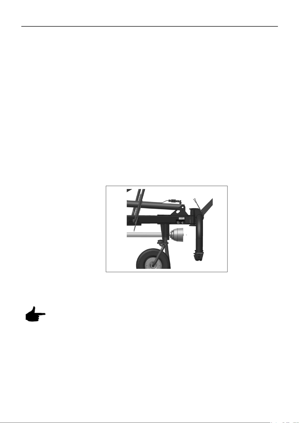
Fig. 3-3 3. The handle for the change-over valve is turned to the symbol "chassis frame"
(C) and the chassis frame is swivelled to the rear. Now the big wheels are
mounted.
Fig. 3-4
The ball valve (fig. 3-2 (1)) in the middle of the chassis frame must be closed!
4. The machine is lifted with the chassis frame and the support wheels are
mounted in working position, wide support wheels are mounted on the middle
frame.

PIGB-188X-03 Z 8805 T 0218
23
Fig. 3-3
Fig. 3-4
PR11-1791
Fig. 3-3
PR14-0323
C
A
D
B
3. MOUNTING OF THE MACHINE AFTER DELIVERY
5. The handle for the change-over valve is turned to the symbol “fold/unfold" (B)
and the left- and right-hand boom arm is unfolded slowly by means of the tractor
hydraulics.
6. The PTO holder is moved forward!
7. All support wheels are mounted in working position.
8. Dismounted tine arms are fastened to the rotor.
9. Warning panels are adjusted to 3 m width.
Fig. 3-4 Mounting of support wheels

3. MOUNTING OF THE MACHINE AFTER DELIVERY
PIGB-188X-03 Z 8805 T 0218
24
Fig. 3-5
P
R
1
1
-
1
7
7
6
135 Nm
Mounting of tine arms:
Fig. 3-5 Pre-mounted tine arms (2) are screwed onto the hub (1) (hexagonal screws M12x40
and 12x35, locknut M12).
Caution! Be aware of the direction of rotation of the rotors! See drawing!
After mounting of the tine arms it must be checked that the tine arms on the
innermost and the outermost rotors are exactly opposite each other.
CONNECTION OF PTO SHAFT
When the machine has been assembled, the PTO shaft can be connected.
The overload clutch must be positioned on the machine side.
The lock-pin on the PTO shaft must be properly engaged in the spline on the
machine’s drive shaft!

3. MOUNTING OF THE MACHINE AFTER DELIVERY
PIGB-188X-03 Z 8805 T 0218
25
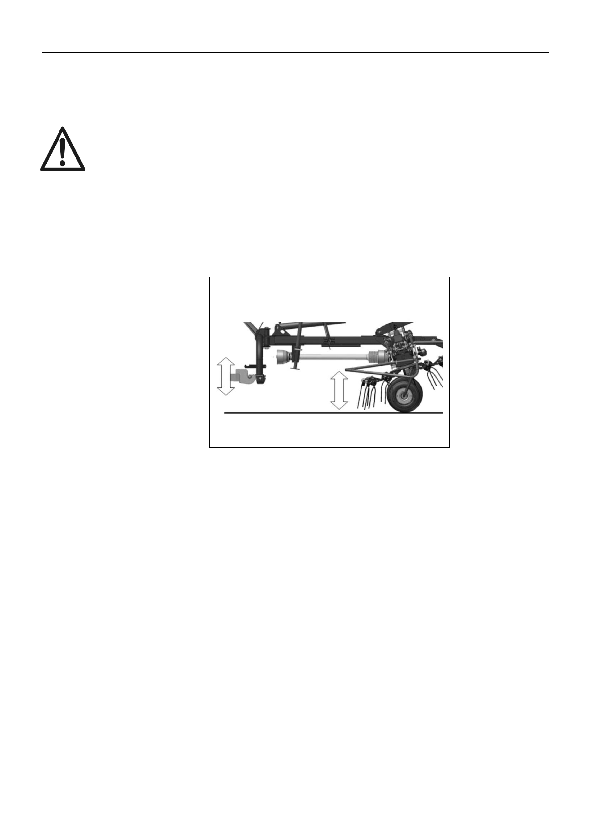
ADJUSTMENT OF PTO DRIVE SHAFT
It may be necessary to shorten the PTO shaft from tractor to machine in order to
prevent it bottoming out in the shortest position. On tractors with a short distance
from PTO to link arm connection, the PTO shaft may be too long.
Important: The profile tubes must have minimum 200 mm overlap! In the
shortest position there must be a distance of minimum 40 mm
from profile tube to universal joint!
The adjustment of the PTO drive shaft takes place as follows:
The tedder and the tractor are placed in the position in which the PTO shaft has
the shortest length (e.g. during turning).
The two PTO shaft half parts are separated.
The one half part is pushed onto the tractor PTO, the other half part onto the
drive shaft of the tedder.
See the instruction manual for the PTO drive shaft for further instructions.
If the tedder is going to be connected to different tractors, it is important to
make sure that the 200 mm overlap and the distance of 40 mm are observed.
For tractors with very different distances between PTO and link arm connection
it is recommendable to have different PTO shafts available.
After the adjustment the swivel area and clearance of the PTO shaft must be
checked! The PTO shaft should not in any position get in contact with machine
parts.

3. MOUNTING OF THE MACHINE AFTER DELIVERY
PIGB-188X-03 Z 8805 T 0218
26
Fig. 3-6
PR14-0319
2
1
2
MOUNTING OF OPTIONAL EQUIPMENT
SUPPORT WHEEL
Mounting of this equipment is shown in the supplied spare parts book.
Fig. 3-6 The support wheel is mounted on the plate above the left hitch pin.
The desired height is adjusted with the spring pin (1) and fixed with the ring screw (2)
to avoid vibrating.

3. MOUNTING OF THE MACHINE AFTER DELIVERY
PIGB-188X-03 Z 8805 T 0218
27
Fig. 3-7
PR13-0320
ANTI-WRAPPING PLATE
Mounting of this equipment is shown in the supplied spare parts book.
NIGHT SWATH GEARBOX
Fig. 3-7 Mounting of this equipment is shown in the supplied spare parts book.
The standard front protection and the PTO shaft are dismounted.
The adapter ring is mounted and the swath gearbox is pushed onto the spline
shaft on the adapter ring.
The night swath gearbox is secured with clamping screw.
The PTO shaft is pushed onto the offset spline shaft.

3. MOUNTING OF THE MACHINE AFTER DELIVERY
PIGB-188X-03 Z 8805 T 0218
28
FUNCTIONAL TEST
After the preparation of the machine, a functional test must be carried out.
Incorrect mounting of the machine is highly dangerous. Before the functional test is
carried out, please check that everything is mounted correctly according to the
instructions in the manual and the mounting guide.
Make sure that there are no tools in the area around the machine!
Make sure that there are no persons in the danger zone!
After 5 hours of operation all screws must be re-tightened to ensure a safe operation!

4. MOUNTING OF THE TEDDER/PREPARATION
PIGB-188X-03 Z 8805 T 0218
29
Fig. 4-1
4. MOUNTING OF THE TEDDER /
PREPARATION
Always disengage the PTO drive shaft before maintaining, repairing and
mounting. Stop the engine and remove the ignition key. Secure the tractor
and the rotary tedder so that they cannot move!
The maximum number of revolutions is 540 rpm.
Operating parts such as cords, hydraulic hoses and cables must be
placed so that unintended operation and contact with the tractor wheels
are impossible. Danger!
During raising and lowering never stand between the tractor and the
tedder or under the raised rotor arms. Risk of personal injury!
Before starting the PTO check that there are no persons in the danger
zone of the rotary tedder. Danger!
Before work and transport on public roads always make sure that all
guards are mounted correctly and locked where appropriate! Check that
the lighting equipment is working.
The operator should never leave the tractor during working! Make sure
that there are no persons in the danger zone!
SPECIAL INSTRUCTIONS
In the area of the 3-point suspension there is a risk of personal injury since
there are places where you can get jammed or cut!
Fig. 4-1 Be particularly careful during connection and disconnection of machines!
Never stand between the tractor and the tedder during connection to the link arms.
The operator should not step into the danger zone until the electric cables, the
hydraulic hoses and the PTO are to be connected.
The operating elements of the tractor must be secured against unintended use
before connection and disconnection.

4. MOUNTING OF THE TEDDER/PREPARATION
PIGB-188X-03 Z 8805 T 0218
30
Fig. 4.2
PR13-0321
Fig. 4-3
P
R
1
3
-
0
2
9
7
PREPARATION OF TRACTOR
3-POINT SUSPENSION ON THE TRACTOR
Fig. 4-2 The tedder Z 8805 T is equipped with hitch pins cat. 2. Depending on the equipment
of the tractor, balls can be installed.
The sideways movement of the link arms on the tractor must be minimised in order to
avoid oscillation of the machine during work and transport. Therefore the link arms
must be secured with limiting chains or other locking device.
Fig. 4-3 Adjust the link arms of the tractor so that they are at the same height above the
ground at both sides.

4. MOUNTING OF THE TEDDER/PREPARATION
PIGB-188X-03 Z 8805 T 0218
31
PLACEMENT OF CORD
It should be possible to operate the cord for the locking pawl from the tractor seat. It
must be ensured that it does not get jammed and is not placed on sharp edges. The
cord must be relieved when the pawls are lowered.
HYDRAULIC SYSTEM (RESTRICTION)
The lifting cylinders of the rotary tedder are equipped with restrictors. No adjustments
should be made on the tractor.
ELECTRIC SYSTEM
The lighting system (option) is equipped with a 7-pole plug for the trailer socket.
CONNECTION OF THE ROTARY TEDDER TO THE
TRACTOR
The instructions are based on a fully mounted rotary tedder in locked transport
position with the support folded down.
CONNECTION TO THE LINK ARMS AND TOP LINK OF THE TRACTOR
Never stand between the tractor and the tedder during connection to the
tractor.
Make sure that there are no persons in the swivel area of the rotor arms!
The pins on the suspension of the tedder are connected to the link arms of the tractor
and secured.
The power transmission (PTO shaft) as well as the electric and hydraulic
connections must be established before the support is pushed up since the
operator has to step into the danger zone.

4. MOUNTING OF THE TEDDER/PREPARATION
PIGB-188X-03 Z 8805 T 0218
32
Fig. 4-4
PR14-0322
1
Fig. 4-5
PR14-0330
2
1
1
1
2
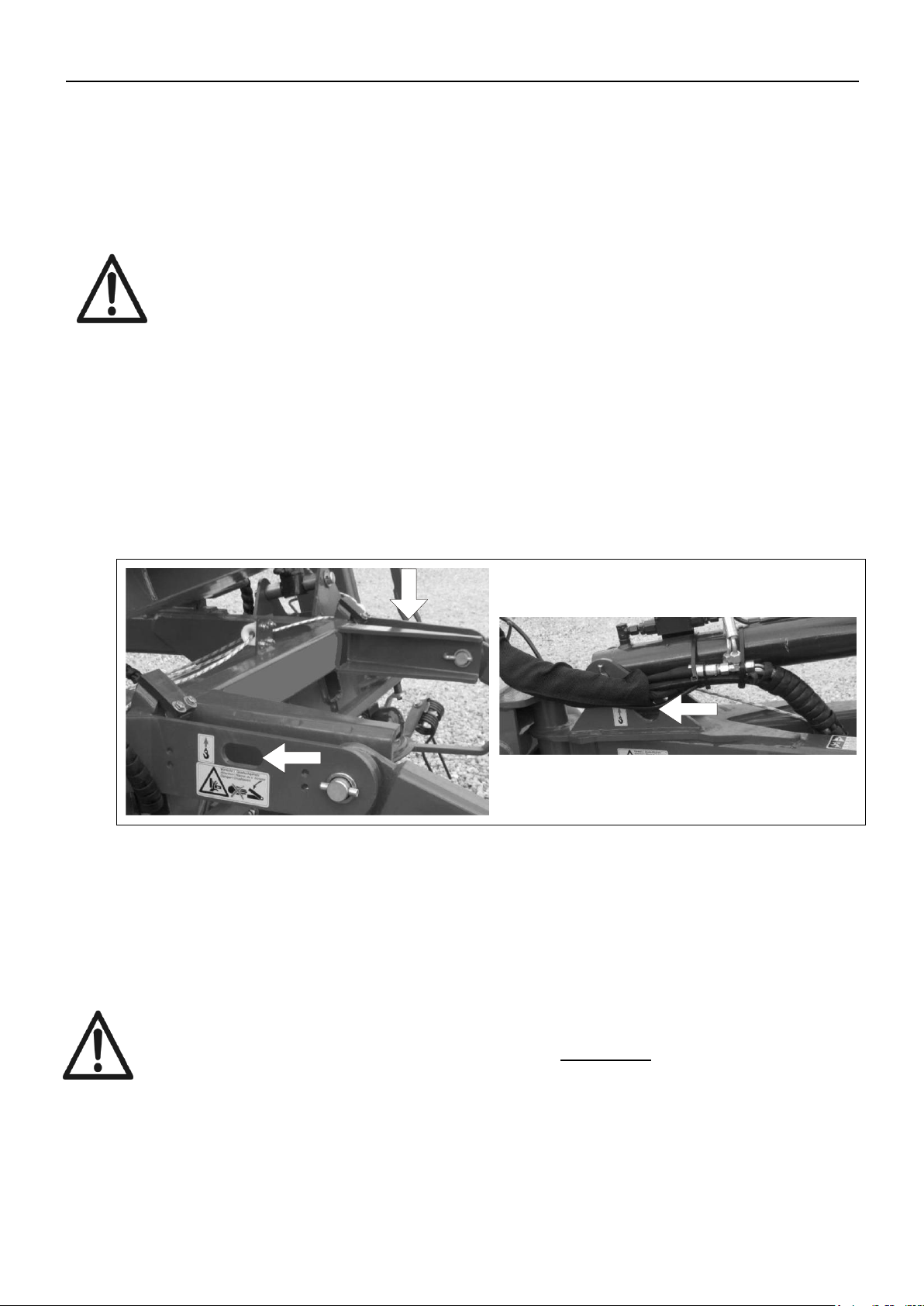
Fig. 4-4 Raise the machine with the link arms until the support is raised from the ground.
Release the support by pulling out the spring pin (1).
Push up the support and lock it with the spring pin.
Fig. 4-5 At the linkage there is a holder (1) with a control box (2) for operation of the tedder.
The holder has many adjustment possibilities. The two adjustment screws on the
holder are loosened and the control box is mounted at about 30 cm distance to the
cabin. The screws are tightened again.
The control box must be mounted at sufficient distance to the cabin / rear
window!
When the machine is in headland position / transport position and on uneven
ground, the distance between the control box and the tractor is reduced
significantly!
If the machine is used with different tractors it must be checked that the
control box has the correct distance to the tractor!

4. MOUNTING OF THE TEDDER/PREPARATION
PIGB-188X-03 Z 8805 T 0218
33
Fig. 4-6
P
R
1
4
-
0
3
2
3
C
A
D
B
HYDRAULIC CONNECTION
For the conversion from transport to working position the rotary tedder Z 8805 T
needs a double-acting outlet.
For clearing of field boundaries (hydraulic), no additional outlet is needed.
All functions are controlled with a change-over valve.
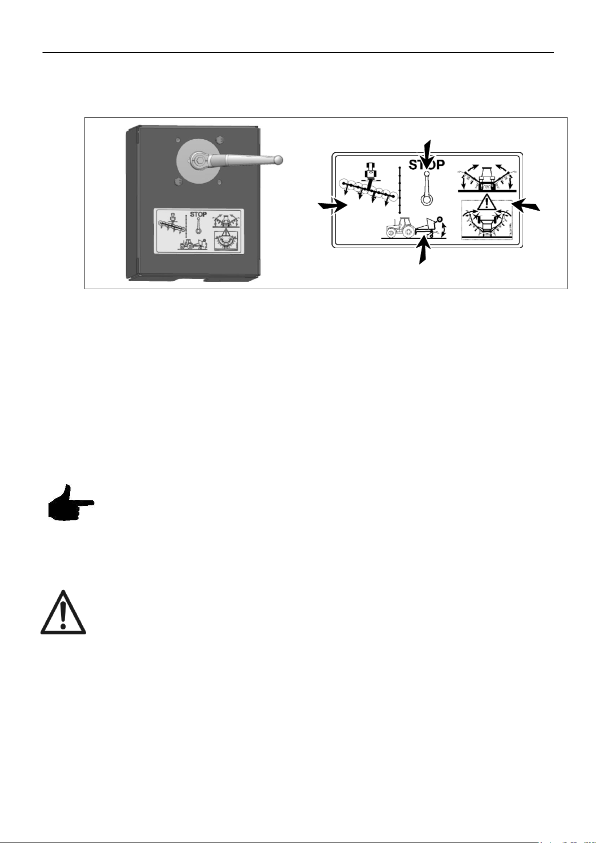
Fig. 4-6 The change-over valve has four positions:
A. Blocking of the hydraulics
B. Folding/unfolding of side arms
C. Swivelling of transport axle
D. Hydraulic clearing of field boundaries
The change-over valve (ball valve) should be opened after the connection to the
tractor hydraulics so that the coupling is not under pressure. When the machine is
parked the pressure may adjust, for instance if the outdoor temperature changes.
CONNECTION OF LIGHTING EQUIPMENT
The tedder Z 8805 T is equipped with lighting according to current rules.
The lighting system is equipped with a 7-pole plug at the lighting cable. Connect this
plug to the socket at the rear of the tractor.
After the connection the function of the lighting system must be checked! Dirt
and moisture may result in contact problems or even short circuit. Therefore
the plug connection must be kept clean and dry. Also check the tractor fuses
for the 7 pin socket are in place and intact.

4. MOUNTING OF THE TEDDER/PREPARATION
PIGB-188X-03 Z 8805 T 0218
34
CONNECTION OF PTO SHAFT
The description implies that the length of the PTO shaft is adjusted to the
tractor according to chapter 3: “Adjustment of PTO drive shaft.”
If the machine is used with different tractors it must be checked that the PTO
shaft has the correct length.
On the tractor and machine side there must be an intact guard.
Only use the supplied PTO shaft or a PTO shaft that is approved by the
manufacturer!
Release the PTO shaft from the support chain.
Push the PTO shaft onto the tractor PTO until the locking balls are engaged.
The guard of the PTO shaft must be fastened with safety chains on the tractor
in order to avoid that it rotates.
TRANSPORT ON PUBLIC ROADS
The ball valve of the change-over valve must be closed. This is done by
placing it in position “STOP”.
When driving on public roads the current traffic rules with regard to
lighting must be observed!
The maximum speed of 40 km/h should not be exceeded.
Always adjust the driving speed to the conditions of the road.
5. HANDLING OF THE TEDDER DURING WORKING
PIGB-188X-03 Z 8805 T 0218
35
PR11-1778
Åben
Open
Offen
Lukket
Closed
Geschlossen
Fig. 5-1
PR13-0331
5. HANDLING OF THE TEDDER DURING
WORKING
The following description implies that the tedder is completely mounted according to
chapter 3 and connected to the tractor according to chapter 4. The machine is in
transport position.
CONVERSION OF THE TEDDER FROM TRANSPORT
TO WORKING POSITION
For conversion from transport to working position, the machine is placed
on even ground or uphill. Avoid slopes where the tractor and the machine
may slide down or overturn. The side arms may swivel out uncontrolled
whereby the machine might get damaged.
When placing the machine on slopes, the risk of overturning and personal
injury is increased.
Make sure that there are no persons in the swivel and working area. There
is danger of getting hit by the machine.
Fig. 5-1
THE STOP VALVE IN THE CENTRE OF THE MACHINE
The stop valve in the centre of the machine must be open. The descriptions
below are based on this position!
With open stop valve the transport axle and the rotor arms are swivelled
simultaneously.
5. HANDLING OF THE TEDDER DURING WORKING
PIGB-188X-03 Z 8805 T 0218
36
Fig. 5-2
P
R
1
4
-
0
3
2
3
C
A
D
B
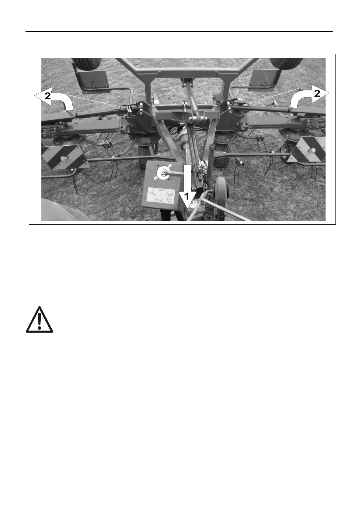
UNFOLDING THE MACHINE IN WORKING POSITION
Fig. 5-2 The change-over valve is switched from position “STOP" (A) to
“folding/unfolding of side arms” (B) or to “swivelling of transport axle” (C). With
open stop valve the function is identical.
With the double-acting outlet of the tractor the machine is unfolded in a smooth
movement. The side arms are now unfolded completely and the transport axle
is swivelled up.
In working position the hydraulic cylinders of the rotor arms must be fully
extended. The transport axle is swivelled up completely. During working the
outlet of the tractor must stay in the position "Neutral". Do not pull the cord while
the machine is being unfolded.
The side arms must be unfolded in a smooth movement.
In case of malfunction, the side arms are folded again and the procedure is repeated
with increased number of rpm.
STARTING THE ROTOR
Check that there are no persons near the machine before starting the rotor!
Always start the PTO of the tractor with the engine at idle speed!
The tedder is now ready for operation!

PIGB-188X-03 Z 8805 T 0218
37
Fig. 5-3
PR14-0327
Fig. 5-3
5. HANDLING OF THE TEDDER DURING WORKING
POSITION WHEN DRIVING ON HEADLANDS
The stop valve in the centre of the machine must be open. The descriptions
below are based on this position.
The rotary tedder has a defined position for driving of headlands. In this position the
rotors are lifted so much that the outermost rotors do not touch the ground. The
rotary tedder is lifted with the transport axle. The change-over valve is switched to
position “folding/unfolding of side arms” (B) or “swivelling of transport axle” (C). After
this hydraulic outlet on the tractor is activated in direction “raise” until the stop of the
locking pawls is in contact with the hydraulic cylinders of the rotor arms at front and
the transport axle is swivelled completely down. The locking pawls should not be
raised with the cord!

5. HANDLING OF THE TEDDER DURING WORKING
PIGB-188X-03 Z 8805 T 0218
38
Fig. 5-4
PR11-1779
Fig. 5-2
PR14-0323
C
A
D
B
SPREADING FROM FENCE
With the spreading from fence feature the machine can be placed in an offset
position to the right or left. During spreading from fence the machine runs in an offset
position behind the tractor which means that the crop is not thrown out to the field
boundary.
Fig. 5-2 The handle for the change-over valve is turned to position “spreading from fence”
(D).
Fig. 5-4 During working the machine is placed in the offset position with the hydraulic outlet of
the tractor.

5. HANDLING OF THE TEDDER DURING WORKING
PIGB-188X-03 Z 8805 T 0218
39
Fig. 5-5
PR13-0303
Fig. 5-5 For normal tedding the wheels are returned to middle position.
When avoiding obstacles or driving along fences there must be enough
distance to the rotors!

5. HANDLING OF THE TEDDER DURING WORKING
PIGB-188X-03 Z 8805 T 0218
40
CONVERSION OF THE TEDDER FROM WORKING TO
TRANSPORT POSITION
For conversion from working to transport position, the machine is placed
on even ground or uphill. Avoid slopes where the tractor and the machine
may slide down or overturn.
When placing the machine on slopes, the risk of overturning and personal
injury is increased.
Make sure that there are no persons in the swivel and working area.
FOLDING TO TRANSPORT POSITION
Place the machine with all rotor wheels firmly on the ground. Disconnect the
PTO!
The stop valve in the centre of the machine must be open. The descriptions
below are based on this position!
5. HANDLING OF THE TEDDER DURING WORKING
PIGB-188X-03 Z 8805 T 0218
41
PR14-0332
Fig. 5-6
Fig. 5-6
The change-over valve is switched to position “folding/unfolding of side arms” or
“swivelling of transport axle”.
Pull the cord (1) for lifting the locking pawls (2) until the stop is reached.
Afterwards activate the outlet on the tractor in direction “raise”. Hold the cord
until the outermost arms have been folded in and the tension in the cord yields.
Fold the machine further in to the final transport position.
The machine must be lifted completely with the transport axle and the side
arms must be folded in!
5. HANDLING OF THE TEDDER DURING WORKING
PIGB-188X-03 Z 8805 T 0218
42
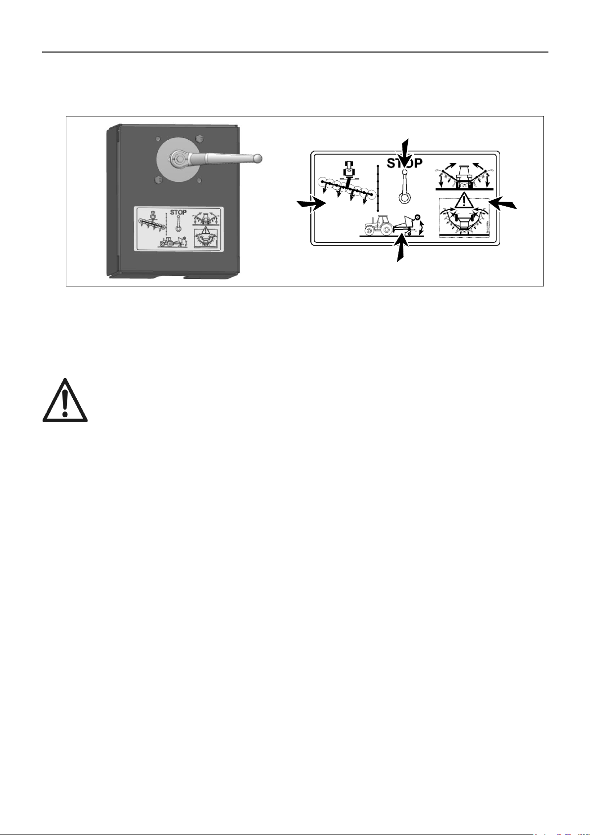
Fig. 5-2
P
R
1
4
-
0
3
2
3
C
A
D
B
BLOCKING OF THE HYDRAULICS
Fig. 5-2 The change-over valve is switched to position “STOP” (A).
The rotary tedder is now ready for transport!
In order to obtain safe transport, the steering and braking capacity of the tractor
must be maintained in spite of the mounted machine. In this connection the
instructions of the tractor manufacturer should be observed.
It may be necessary to ensure a better weight distribution to the front axle.
This can be checked by means of chapter 10.

5. HANDLING OF THE TEDDER DURING WORKING
PIGB-188X-03 Z 8805 T 0218
43
Fig. 5-7
P
R
1
1
-
1
7
8
0
Åben
Open
Offen
Lukket
Closed
Geschlossen
Fig. 5-2
P
R
1
4
-
0
3
2
3
C
A
D
B
SWIVELLING OF TRANSPORT AXLE
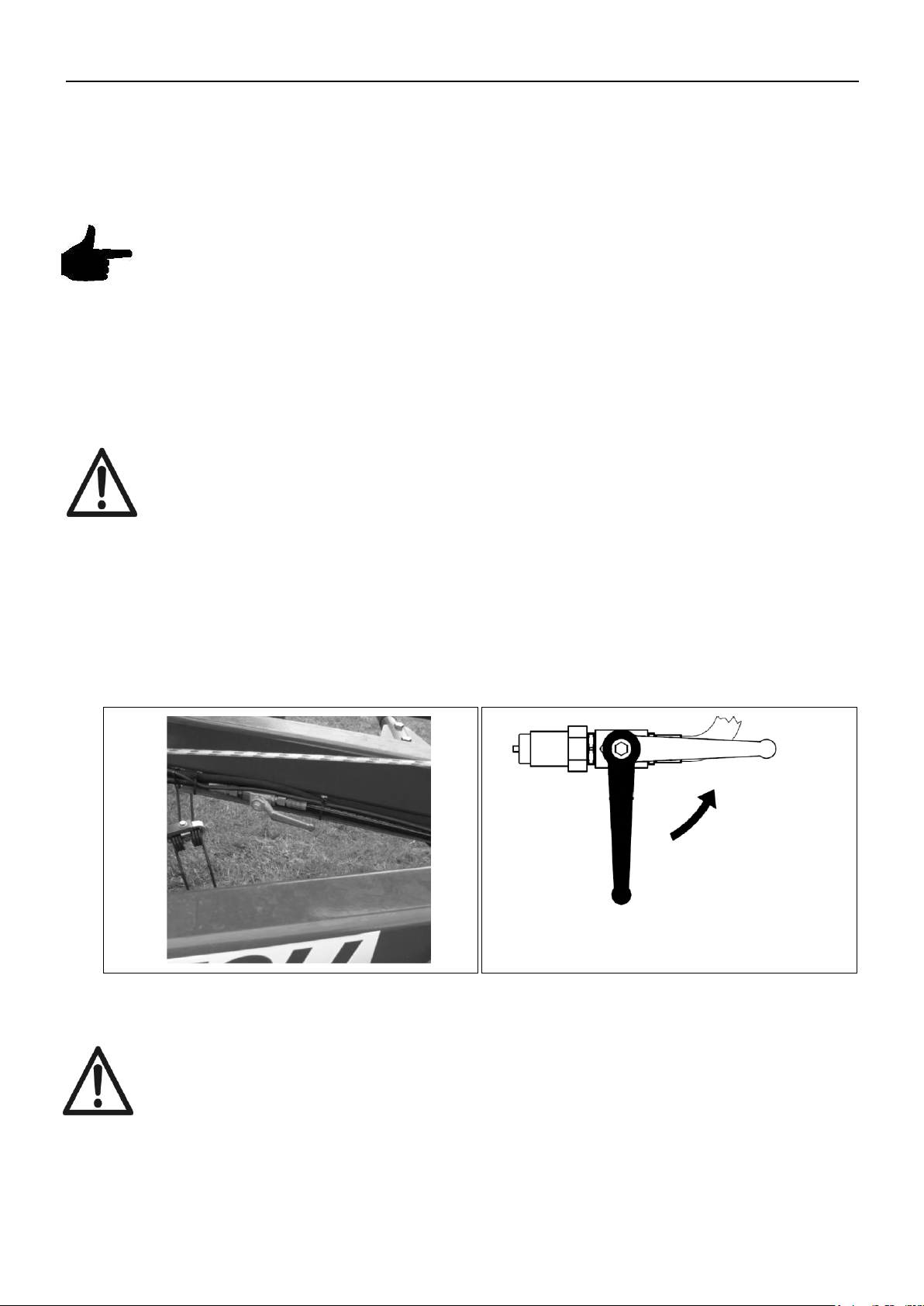
Fig. 5-7 The transport axle can be swivelled without moving the rotor arms. For this purpose
the stop valve in the centre of the machine must be closed.
Fig. 5-2 The change-over valve is switched to position “Swivelling of transport axle” (C).
The axle can now be swivelled by means of the tractor’s hydraulic outlet. The side
arms must be unfolded completely to avoid machine damage.
The side arms must be unfolded completely. Otherwise there is a risk of
collision with machine parts!

5. HANDLING OF THE TEDDER DURING WORKING
PIGB-188X-03 Z 8805 T 0218
44
Fig. 5-7
P
R
1
1
-
1
7
8
0
Åben
Open
Offen
Lukket
Closed
Geschlossen
Fig. 5-2
P
R
1
4
-
0
3
2
3
C
A
D
B
FOLDING OF SIDE ARMS
Fig. 5-7 Like the transport axle, the side arms can be swivelled without moving the rotor arms.
For this purpose the stop valve in the centre of the machine must be closed.
Fig. 5-2 The change-over valve is switched to position “folding/unfolding of side arms” (B).
The side arms can now be swivelled by means of the tractor’s hydraulic outlet. The
transport axle must be swivelled completely down to avoid machine damage.
When swivelling the side arms there is a risk of collision with other machine
parts! The transport axle is swivelled down!
5. HANDLING OF THE TEDDER DURING WORKING
PIGB-188X-03 Z 8805 T 0218
45
Fig. 5-8
DISCONNECTION OF THE MACHINE
The rotary tedder must be in transport position.
The hydraulic system should not be under pressure and the change-over
valve must be closed.
The ground must be sufficiently firm and even.
Before the disconnection, the rotary tedder must be secured with stop
blocks so that it cannot move!
Fig. 5-8 Procedure:
Choose a sufficiently firm, dry and even ground.
Release the support, push it down and lock it with the spring pin.

5. HANDLING OF THE TEDDER DURING WORKING
PIGB-188X-03 Z 8805 T 0218
46
The link arms of the tractor are lowered until the support rests safely on the
ground.
The tedder is secured with stop blocks so that it cannot move.
Disconnect the PTO shaft from the tractor and place it in the holder.
The change-over valve is switched to position “STOP”. The hydraulic hoses are
disconnected and placed in the holder at the suspension. (Make sure that the
system is not under pressure while this is done!).
The lighting cable is disconnected and placed in the holder at the suspension.
The link arms of the tractor are released from the tedder and the machine is
disconnected.
Make sure that the machine is placed on firm and even ground so that it is not
in danger of turning over.
Only park the machine on the transport axle and the support.
6. BASIC ADJUSTMENT OF THE TEDDER
PIGB-188X-03 Z 8805 T 0218
47
Fig.6-1
PR14-0324
6. BASIC ADJUSTMENT OF THE TEDDER
During basic adjustment, the PTO must be disconnected!
The tractor engine must be stopped!
Never work under the rotors without sufficient support!
ADJUSTMENT OF WORKING DEPTH
The distance of the tines to the ground is adjusted in working position with the top
link of the tractor.
Fig. 6-1 The machine is aligned by driving forward briefly.
Adjust the working depth with the top link so that the double tines touch the
ground slightly.
Note:
If the tines are adjusted too low, there is danger of contamination of the feed
and damage to the grass roots. The tines are worn unnecessarily.
If the tines are adjusted too high, clean raking cannot be obtained.
The adjustment must be checked during the operation.

6. BASIC ADJUSTMENT OF THE TEDDER
PIGB-188X-03 Z 8805 T 0218
48
Fig.6-2
PR13-0306
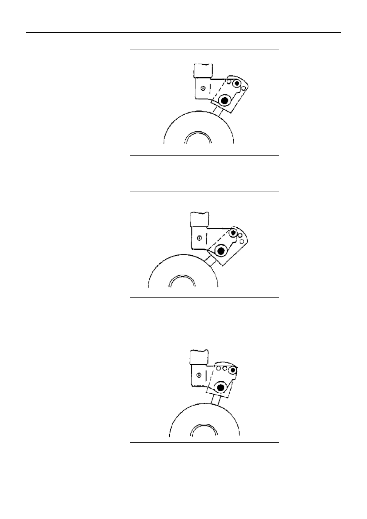
ADJUSTMENT OF SPREADING ANGLE
Fig. 6-2 The support wheels can be set to different spreading angles. The adjustment takes
place by adjusting the wheel bracket on the wheel carrier.
The machine must be lifted to adjust the spreading angle.
The adjustment must take place in consideration of the conditions. The following
usually applies:
6. BASIC ADJUSTMENT OF THE TEDDER
PIGB-188X-03 Z 8805 T 0218
49
P
R
1
1
-
1
7
8
1
N
Fig.6-3
P
R
1
1
-
1
7
8
2
F
Fig.6-4
Fig.6-5
P
R
1
1
-
1
7
8
3
S
Fig. 6-3 Normal spreading angle = pos. N.
Fig. 6-4 Small spreading angle for dry material = pos. F.
Fig. 6-5 Big spreading angle = pos. S.

6. BASIC ADJUSTMENT OF THE TEDDER
PIGB-188X-03 Z 8805 T 0218
50
All wheels must have the same adjustment!
If, for changing the spreading angle, another adjustment of the wheels is used than
prescribed by the factory, the top link must also be adjusted - in order to ensure that
the tines of the tedder are adjusted correctly for picking up the material.
WORKING SPEED AND NUMBER OF REVOLUTIONS
The working speed and the number of rpm during tedding and swath spreading
depend on the type and amount of crop, the dry matter content and the ground
conditions.
The following can be used as a guide:
PTO number of revolutions, approx. 400 - 540 RPM
Driving speed, approx. 4 - 15 km/h
Both values must be adjusted to the working conditions.
DRIVING SPEED AND NUMBER OF REVOLUTIONS
Choose the driving speed at which the rotary tedder picks up the material completely.
Choose the number of revolutions on the PTO at which the material is processed
correctly.
This depends on the condition of the material, i.e. the drier the material, the lower the
number of revolutions.
SPREADING OF MOWN SWATHS
You should drive so that there is a swath between the tractor wheels. The working
speed depends on the condition of the material. The number of revolutions of the
PTO must be about 540 rpm.
The swaths should be divided evenly in relation to the rotors so that the tractor does
not drive on the material.
TEDDING
During tedding of spread material, you should work at a low number of rpm - but at a
higher driving speed - in order to avoid loss of crop due to crumbling. Check whether
the chosen relation between driving speed and number of revolutions gives the
desired result. Adjust if necessary.

6. BASIC ADJUSTMENT OF THE TEDDER
PIGB-188X-03 Z 8805 T 0218
51
SPREADING OF SWATHS
You should drive so that there is a swath between the tractor wheels.
The number of rpm of the PTO should be so low that the swaths are spread with a
very gentle treatment of the material.
The driving speed should be adjusted according to the result.
NIGHT SWATHS
With the swath gearbox mounted small single swaths are made at maximum 300 400 rpm on the PTO. The driving speed should be adjusted according to the result.
Do not cross the swaths. This would result in irregular load of the machine and
a bad spreading pattern.

7. SERVICE AND MAINTENANCE OF THE TEDDER
PIGB-188X-03 Z 8805 T 0218
52
7. SERVICE AND MAINTENANCE OF THE
TEDDER
SAFETY RULES
Maintenance, service, cleaning and repair must only take place when the
PTO and the engine have been stopped. Remove the ignition key!
Take care that oil and grease do not get in contact with your skin.
After the first hours of operation all screws must be re-tightened!
GENERAL MAINTENANCE INSTRUCTIONS
To obtain high operational safety and minimum wear there are certain
maintenance and service intervals which must be observed. This includes e.g.
cleaning, greasing and lubrication of parts and components.
Screws and nuts must be checked after every 50 hours of operation and re-
tightened if necessary!
See the table for torque settings in chapter 2. MAINTENANCE.
It is particularly important to check the fixing bolts of the rake tines on the tine
arms.
Only use original spare parts and equipment. There is no warranty on non-
original components. The manufacturer is not responsible for any damage
resulting from such use.
CLEANING OF THE MACHINE AND PREPARATION
FOR WINTER STORAGE
CLEANING OF THE MACHINE
When cleaning with a high pressure cleaner never spray directly on bearings.
After cleaning, all bearings must be greased carefully until grease comes out of
the bearings to ensure that possible water is pressed out.
When cleaning with high pressure the paint may be damaged. Therefore
sufficient distance must be kept between the nozzle on the high pressure
cleaner and the machine.
Polished parts, e.g. piston rods, require thorough drying to avoid possible
damage.

7. SERVICE AND MAINTENANCE OF THE TEDDER
PIGB-188X-03 Z 8805 T 0218
53
Wheels
Tyre pressure
(bar)
Rotor wheels
18.5-8.50-8 (6PR)
2.5
Rotor wheels
16-6.50-8 (6PR)
1.5
Transport wheels
10.0/80-12
2.5
Extra support wheel
(option)
18.5-8.50-8 (6PR)
2.5
PLACEMENT OF THE MACHINE IN THE OPEN
If the tedder is placed in the open for a longer period, all bearings must be
greased according to the lubrication schedule.
Parts polished such as piston rods of the hydraulic cylinders must be cleaned
and brushed with grease to protect against wind and weather.
WINTER STORAGE
Check the tedder for damaged parts, loose screw-joints and leakage. If there is
any damage it may be forgotten during the winter and result in problems the
following year. Therefore the machine must be checked carefully before the
winter storage.
Grease the tedder according to the lubrication chart.
Clean the machine carefully.
The machine must be stored in a place where it is protected against wind and
weather in the best possible way.
Parts polished must be greased to protect against rust.
The PTO shaft is dismounted and the inner and outer tubes are separated.
Grease the sliding surfaces and reassemble.
WHEELS
The wheels must be checked regularly for damage and correct tyre
pressure.
Wheel-fixing bolts must be checked regularly and re-tightened if
necessary!
Repair of wheels should only be made by experts and with correct tools!
Mounting of wheels requires correct mounting tools and must be
performed by persons with sufficient knowledge.
When working with the wheels the tedder must be secured so that it
cannot move!
TYRE PRESSURE
The tyre pressure must be checked regularly and adjusted if necessary. The required
tyre pressure is shown in the table below:
Caution: If the pressure is too high the tyres may crack. If the pressure is too low the
tyres may be damaged due to deformation of the tyre wall.

7. SERVICE AND MAINTENANCE OF THE TEDDER
PIGB-188X-03 Z 8805 T 0218
54
PTO SHAFTS
When working with the PTO shafts:
Stop the engine!
Remove the ignition key!
INSTRUCTIONS REGARDING PTO SHAFTS:
Never use PTO shafts without guards or if guards are damaged. Risk of
personal injury!
Missing or damaged protection tubes and covers must be replaced immediately!
Only use PTO shafts that are approved by the manufacturer!
Grease the PTO shafts carefully according to the lubrication chart.
HYDRAULIC SYSTEM
Liquids under pressure can penetrate the skin. Danger of infection!
In case of personal injury caused by oil under pressure, consult a doctor
immediately.
After the first 10 hours of operation all hydraulic couplings must be re-
tightened!
Before working with the tedder all hydraulic hoses must be checked for
wear and damage.
If hydraulic hoses are worn or damaged they must be replaced
immediately.
Hydraulic hoses have a natural aging. They are marked with date of production. The
law prescribes that hydraulic hoses are replaced after 6 years.
Only use original spare parts when replacing!
When working with the hydraulic system make sure that it is not under
pressure!
The rotors of the tedder must stand firmly on the ground!

8. MAINTENANCE - GREASE CHART
PIGB-188X-03 Z 8805 T 0218
55
Fig.8-1
P
R
1
1
-
1
7
8
4
8. MAINTENANCE - GREASE CHART
Maintenance, service, cleaning and repair must only take place when the
PTO and the engine have been stopped. Remove the ignition key!
Take care that oil and grease do not get in contact with your skin!
During greasing the rotary tedder must be in working position and parked
safely and firmly on the ground!
This chapter describes all grease points as well as service intervals. The observance
of the following instructions is a precondition for the operational safety and long life of
the machine.
PTO SHAFT
The rotary tedder is equipped with a PTO shaft with overload protection.
Fig. 8-1 The grease spots on the PTO shaft must be greased with universal grease according
to the intervals indicated.
See also the instruction manual for the PTO drive shaft.

8. MAINTENANCE - GREASE CHART
PIGB-188X-03 Z 8805 T 0218
56
Fig.8-2
P
R
1
1
-
1
7
8
5
Fig.8-3
P
R
1
1
-
1
7
8
6
GEARBOXES
The centre gearbox and the rotor gearboxes are maintenance-free. The oil level
should only be checked if there is a noticeable loss of oil with the machine in
horizontal position.
Fig. 8-2 Centre gearbox:
Oil level: 1.2 litres
Quality: SAE 90 API-GL-4
Fig. 8-3 Rotor gearbox:
Fluid grease: 0.2 kg
Quality: Shell Alvania EP

PIGB-188X-03 Z 8805 T 0218
57
Fig. 8-4
PR11-1848
Fig. 8-4 Fingerclutch:
Graphitegrease:
Quality: Molykote BR2 Plus
8. MAINTENANCE - GREASE CHART

8. MAINTENANCE - GREASE CHART
PIGB-188X-03 Z 8805 T 0218
58
Fig.8-5
PR14-0309
1
Fig.8-6
P
R
1
4
-
0
3
1
0
GREASE SPOTS ON THE TEDDER
JOINTS
Fig. 8-5 1. Hinge pins - 25 hours
12 grease points
Fig. 8-6 2. Joint piece - weekly / 50 hours
4 grease points
3. Boom arm - weekly / 50 hours
4 grease points

8. MAINTENANCE - GREASE CHART
PIGB-188X-03 Z 8805 T 0218
59
Fig.8-7
P
R
1
4
-
0
3
1
1
Fig.8-8
P
R
1
4
-
0
3
1
0
Fig. 8-7 4. Steering rod - weekly / 50 hours
4 grease points
OBLONG HOLE (GUIDE)
Fig. 8-8 5. Oblong hole - weekly / 50 hours
4 grease points
8. MAINTENANCE - GREASE CHART
PIGB-188X-03 Z 8805 T 0218
60
Fig.8-9
P
R
1
4
-
0
3
2
5
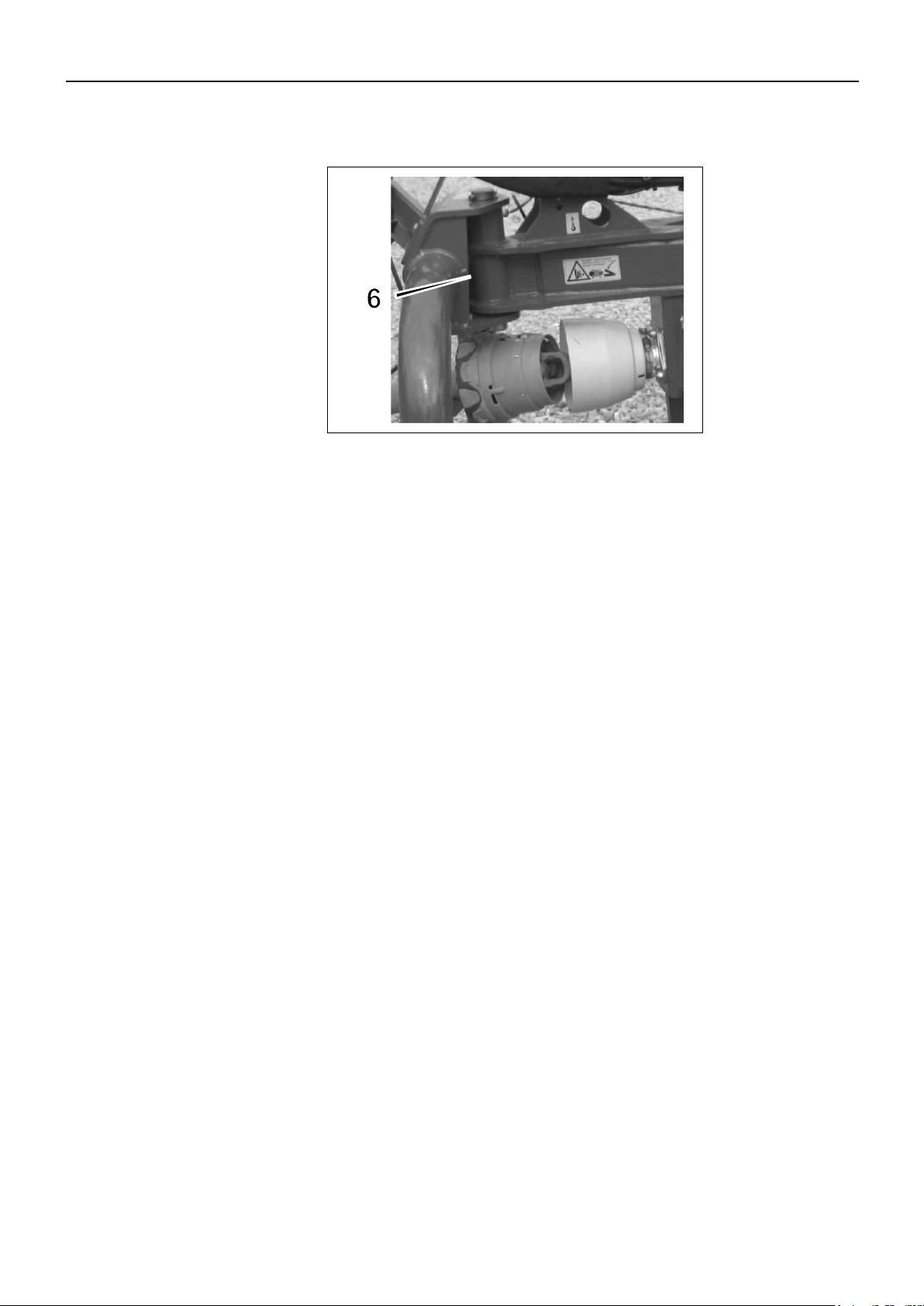
HEADSTOCK
Fig. 8-9 6. Hinge pin - weekly / 50 hours
1 grease point
8. MAINTENANCE - GREASE CHART
PIGB-188X-03 Z 8805 T 0218
61
PR14-0326
Fig.8-10
GREASE CHART OVERVIEW
Fig. 8-10 The following plant-based oil and grease types can be used:
Grease:
PLANTOGEL 2-S
Oil:
PLANTOHXTRAC
Drained oils must be handed over to a recycling company!

9. MACHINE DISPOSAL
PIGB-188X-03 Z 8805 T 0218
62
9. MACHINE DISPOSAL
When the machine is worn-out it must be disposed of in a proper way. Observe the
following:
The machine must not be placed somewhere outside; it must be emptied of oil
(gearboxes and hydraulic system). These oils must be handed over to a
recycling company.
Disassemble the machine and separate the individual parts, e.g. tyres,
hydraulic hoses, hydraulic valves etc.
Hand over the usable parts to an authorised recycling centre. The large
scrapping parts are handed over to an authorised breaker's yard.

10. SUPPLEMENT
PIGB-188X-03 Z 8805 T 0218
63
Supplement C
(informative)
Stability with the combination tractor – rotary tedder and rake
This supplement concerns 6.1.f) in this part of ISO 4254 which deals with the requirement of
informing of possible loss of the tractor’s stability due to the connection of the machine.
The following text is a suggestion to the manufacturer with the purpose of making it possible for him
to provide suitable and complete information.
The example concerns a rotary tedder and rake connected to a tractor.
Due to the own weight of the machine, the combination tractor – rotary tedder and rake can become
unstable. In order to test the total stability the following formula can be used for the calculation of the
minimum front ballast I
F,min
at a minimum front axle load of 20% of the tractor’s own weight:
ANNOTATION In this calculation rear-mounted implements and front/rear combinations have
been taken into consideration.
10. SUPPLEMENT
Translation from Norm EN ISO 4254-10

10. SUPPLEMENT
PIGB-188X-03 Z 8805 T 0218
64
List of signs
TE [kg] The tractor’s own weight 1)
TF [kg] Front axle load with empty tractor 1)
TR [kg] Rear axle load with empty tractor 1)
IR [kg] Total weight rear-mounted implement/rear ballast 2)
IF [kg] Total weight front-mounted implement/front ballast 2)
a [m] Distance between centre of gravity front-mounted implement/front ballast and middle of
front axle 2) 3)
b [m] The tractor’s wheel distance 1) 3)
c [m] Distance between middle of rear axle and middle of link arm balls 1) 3)
d [m] Distance between middle of link arm balls and centre of gravity rear mounted
implement/rear ballast 2)
1) see instruction manual for the tractor
2) see price list and/or instruction manual for the implement
3) to be measured
Picture B.1 Example of references to stability of the combination tractor – rotary tedder and
rake

11. WARRANTY
PIGB-188X-03 Z 8805 T 0218
65
11. WARRANTY
Your machine is warranted according to legal rights in your country and the
contractual agreement with the selling dealer. No warranty shall, however, apply if
the machine has not been used, adjusted and maintained according to the
instructions given in this operator's manual.
It is prohibited to carry out any modifications to the machine unless specifically
authorized, in writing, by a NEW HOLLAND representative.

Maskine: La máquina: Masin:
Maschine: Maszyna: Stroj:
Machine: Машината: Η μηχανή:
Machine: Gép: Máquina:
La macchina: Stroj: Il-magna:
Machine: Mašina: Mašīna:
Maskin: Stroj:
Laite: Maşina:
Model/Type: Z 8805 T
Designation: Tedder
Serial:
EF-overensstemmelseserklæring/ EG-Konformitätserklärung/ EC Declaration of Conformity/ Déclaration CE de
conformité/ Dichiarazione CE di conformita/ EG Verklaring van Overeenstemming/ EG-försäkran om överensstämmelse/
EY-vaatimustenmukaisuusvakuutus/ Declaración de conformidad CE/ Deklaracja Zgodności WE./ Декларация за
съответствие EO/ EK Megfelelőségi Nyilatkozat /ES Prohlášení o shodě/ EB Atitikties deklaracija/ ES prehlásenie o
zhode/ Declaraţia de conformitate CE/ Vastavuse Deklaratsioon EÜ /ES Izjava o skladnosti/ Δήλωση πιστότητας EK/
Declaração de fidelidade CE/ Dikjarazzjoni ta’ Konformità tal-KE/ EK Atbilstības deklarācija/
Fabrikant/ Hersteller/ Manufacturer/ Fabricant/ Produttore/ Fabrikant/ Fabrikant/ Valmistaja/ Fabricante/ Producent/
Производител/ Gyártó/ Výrobce/ Gamintojas/ Výrobca/ Producător/ Tootja/ Proizvajalec/ Κατασκευαστής/ Fabricante/
Fabbrikant/ Ražotājs
CNH INDUSTRIAL BELGIUM N.V.
Leon Claeysstraat 3a, 8210 Zedelgem, BELGIUM
Repræsenteret af Antoon Vermeulen, Leon Claeysstraat 3A, B8210 Zedelgem (Belgien), som også har tilladelse til at
indsamle teknisk dokumentation / vertreten durch Antoon Vermeulen, Leon Claeysstraat 3A, B8210 Zedelgem (Belgium),
der auch autorisiert ist, die technische Akte zu erarbeiten / represented by Antoon Vermeulen, Leon Claeysstraat 3A,
B8210 Zedelgem (Belgium), who is also authorised to compile the Technical File / Répresentés par Antoon Vermeulen,
Leon Claeysstraat 3A, B8210 Zedelgem (Belgique), également autorisé à constituer le dossier technique / rappresentati
da Antoon Vermeulen, Leon Claeysstraat 3A, B8210 Zedelgem (Belgio), autorizzato a compilare il File tecnico /
vertegenwoordigd door Antoon Vermeulen, Leon Claeysstraat 3A, B8210 Zedelgem (Belgium), die tevens is gemachtigd
om het Technisch Bestand samen te stellen / representerade av Antoon Vermeulen, Leon Claeysstraat 3A, B8210
Zedelgem (Belgien), som också har behörighet att sammanställa den tekniska dokumentationen / edustajamme Antoon
Vermeulenin, osoite Leon Claeysstraat 3A, B8210 Zedelgem (Belgium) välityksellä, jolla on myös oikeus laatia tekninen
tiedosto / representados por Antoon Vermeulen, Leon Claeysstraat 3A, B8210 Zedelgem (Bélgica), quien además está
autorizado para recopilar el documento técnico / której przedstawicielem jest Antoon Vermeulen, Leon Claeysstraat 3A,
B8210 Zedelgem (Belgia), który jest również upoważniony do sporządzania dokumentacji technicznej / представлявани
от Антоон Вермьолен, Leon Claeysstraat 3A, B8210 Zedelgem (Белгия), с упълномощение също да състави
Техническото досие / akiket képvisel: Antoon Vermeulen, Leon Claeysstraat 3A, B8210 Zedelgem (Belgium), aki
szintén jogosult a műszaki dokumentumok összeállítására / v zastoupení Antoon Vermeulen, Leon Claeysstraat 3A,
B8210 Zedelgem (Belgium), s autorizací k tvorbě technického souboru / atstovaujami Antoon Vermeulen, Leon
Claeysstraat 3A, B8210 Zedelgem (Belgija), taip pat turintis teisę sudaryti technines bylas / v zastúpení Antoonom
Vermeulenom, Leon Claeysstraat 3A, B8210 Zedelgem (Belgicko), ktorý je oprávnený zostavovať technickú
dokumentáciu / reprezentaţi de Antoon Vermeulen, Leon Claeysstraat 3A, B8210 Zedelgem (Belgia), care este, de
asemenea, autorizat să compileze dosarul ethnic / esindajatega Antoon Vermeulen, Leon Claeysstraat 3A, B8210
Zedelgem (Belgia), kellel on samuti luba tehnilise faili koostamiseks / ki nas zastopa Antoon Vermeulen, Leon
Claeysstraat 3A, B8210 Zedelgem (Belgija), ki je pooblaščen tudi za sestavo tehnične dokumentacije /
εκπροσωπούμενοι από τον Antoon Vermeulen, Leon Claeysstraat 3A, B8210 Zedelgem (Βέλγιο), με εξουσιοδότηση και
για τη σύνταξη του Τεχνικού φακέλου / representados por Antoon Vermeulen, Leon Claeysstraat 3A, B8210 Zedelgem
(Bélgica), que também tem autorização para compilar o Ficheiro Técnico / irrappreżentata minn Antoon Vermeulen Leon
Claeysstraat 3a, B8210 Zedelgem (Belġju), min huwa wkoll awtorizzat li tiġbor l-Fajl Tekniku / Antoon Vermeulen, Leon
Claeysstraat 3A, B8210, Zedelgem (Belgium), pārstāvēti, kas ir pilnvarots arī sastādīt tehnisko reģistru
Erklærer hermed, at/ Erklären hiermit, daß/ Hereby declare that/ Déclare par la présente que/ Dichiara che/ Verklaren
hierbij dat/ Försäkrar härmed, att/ Vakuuttaa täten, että tuote/ Por el presente declara que/ Niniejszym deklaruje, że/
Декларирам, че/ Az alábbiakban kijelentem, hogy/ Tímto prohlašuje, že/ Deklaruoja, kad/ Týmto prehlasujeme, že/ Prin
prezenta declar că/ Alljärgnevaga deklareerib, et/ Izjavljamo, da je/ Με το παρόν δηλώνω ότι/ Abaixo declara que /
Jiddikjaraw li / Apstiprinu, ka
- er i overensstemmelse med Maskindirektivets bestemmelser (Direktiv 2006/42/EF) og hvis relevant også
bestemmelserne i EMC-direktivet 2014/30/EU.
- In übereinstimmung mit den Bestimmungen der Maschinen-Richtlinie 2006/42/EG und wenn erforderlich auch mit der
EMC-Richtlinie 2014/30/EU hergestellt wurde.
- is in conformity with the provisions of the Machinery Directive 2006/42/EC and if relevant also the provisions of the
EMC Directive 2014/30/EU.

- est conforme aux dispositions de la Directive relatives aux machines 2006/42/CE et également aux dispositions de la
Directive sur la Directive EMC 2014/30/UE.
- é in conformita' con la Direttiva Macchine 2006/42/CE e, se pertinente, anche alla Direttiva alla Direttiva EMC
2014/30/UE.
- in overeenstemming is met de bepalingen van de Machine richtlijn 2006/42/EG en wanneer relevant ook met de
bepalingen van de EMC richtlijn 2014/30/EU.
- är i överensstämmelse med Maskindirektivets bestämmelser (Direktiv 2006/42/EG) ock om relevant också
bestämmelserne EMC-direktivet 2014/30/EU.
- täyttää Konedirektiivin (Direktiivi 2006/42/EY) määräykset ja oleellisilta osin myös EMC-direktiivin 2014/30/EU.
- es conforme a la Directiva de Maquinaria 2006/42/CE y, si aplica, es conforme también a la Directiva EMC
2014/30/EU.
- pozostaje w zgodzie z warunkami Dyrektywy Maszynowej 2006/42/WE i jeżeli ma to zastosowanie również z
warunkami Dyrektywy dot. kompatybilności elektro magnetycznej EMC 2014/30/UE.
- отговаря на изискванията на Директивата за Машините 2006/42/EО и ако има приложение на изискванията на
Директивата за електромагнитна съвместимост 2014/30/EC.
- Megfelel a 2006/42/EK Gépi Eszközökre vonatkozó előírásoknak és amennyiben felhasználásra kerül, a 2014/30/EU
Elektromágneses kompatibilitás Irányelv feltételeinek.
- odpovídá základním požadavkům Strojní směrnice 2006/42/ES a jestliže to její uplatnění vyžaduje i s podmínkami
Směrnice 2014/30/EU týkající se elektromagnetické kompatibility.
- atitinka Mašinų direktyvos Nr. 2006/42/EB ir, jeigu taikoma, Elektromagnetinio suderinamumo direktyvos Nr.
2014/30/ES reikalavimus.
- je v súlade s podmienkami Smernice 2006/42/ES o strojných zariadeniach a pokiaľ si to jeho uplatnenie vyžaduje aj
s podmienkami Smernice 2014/30/EÚ o elektromagnetickej kompatibilite.
- îndeplineşte prevederilor Directivei de Maşini 2006/42/CE şi dacă este utilizată de asemenea cu prevederile Directivei
referitoare la compatibilitatea electro-magnetică EMC 2014/30/UE.
- on vastavuses Masinate Direktiivi tingimustega 2006/42/EÜ ning sammuti juhul, kui on tegemist sammuti on vastavuses
Elektromagnetilise kokkusobivuse Direktiivitingimustega EMC 2014/30/EL.
- z določili Direktive o strojih 2006/42/ES ter, če je to relevantno, tudi z določili EMC Direktive 2014/30/EU.
- παραμένει σύμφωνη με τους όρους της Οδηγίας περί Μηχανών 2006/42/ΕΚ και σε περίπτωση που αυτό εφαρμόζεται
και με τους όρους της Οδηγίας περί ηλεκτροµαγνητικής συµβατότητας (ΗΜΣ) 2014/30/EE.
- Está de acordo com exigências das Directivas das Maquínarias 2006/42/CE e no caso em que tiver igualmente
aplicação com as exigências das Directivas referentes a compatibilidade electromagnética EMC 2014/30/UE.
- tikkonforma mad-dispożizzjonijiet tad-Direttiva dwar il-Makkinarju 2006/42/KE u jekk rilevanti wkoll mad-dispożizzjonijiet
tad d-Direttiva EMC 2014/30/EU.
- atbilst mašīnu direktīvai 2006/42/EK, kā arī nepieciešamības gadījumā elektromagnētiskās saderības direktīvai EMC
2014/30/ES.
Zedelgem, date:
Antoon Vermeulen

Dealer’s stamp
CNH Industrial Belgium N.V. reserves the right to make improvements in design and changes in specifications
at any time without notice and without incurring any obligation to install them on units previously sold.
Specifications, descriptions, and illustrative material herein are as accurate as known
at time of publication, but are subject to change without notice.
Availability of some models and equipment builds varies according to the country
in which the equipment is being used. For exact information about any particular product,
please consult your Kongskilde dealer.
© 2018 CNH Industrial Belgium N.V. All Rights Reserved.
Kongskilde is a trademark registered in the United States and many other countries,
owned by or licensed to CNH Industrial N.V., its subsidiaries or affiliates.
Any trademarks referred to herein, in association with goods and/or services of companies, other than owned by or licensed to
CNH Industrial N.V., its subsidiaries or affiliates, are the property of those respective companies.
 Loading...