

Kongskilde FCT 1260, FCT 1460, FCT 1260MD, FCT 1460MD Operator's Manual

ORIGINAL INSTRUCTIONS - according to Directive 2006/42/EC, Annex I 1.7.4.1
OPERATOR’S MANUAL
FCT 1260
FCT 1460
Harvester
Part number 81PIGB-206x
1st edition English
February 2018


PIGB-206B-02 FCT 1260-1460 0218
- 3 -
FOREWORD
DEAR CUSTOMER!
We appreciate the trust and confidence you have shown in our company by investing
in a KONGSKILDE product, and hope your new machine gives you many years of
reliable service. We want you to be completely satisfied with your investment.
This user manual contains information which when followed will ensure that the
machine is used safely and correctly.
When your machine was delivered, your dealer will have gone through the machine’s
operation, settings and maintenance with you.
However, this initial introduction is no substitute for a thorough understanding of
the various operations, functions and correct use of the machine.
You should therefore read this user manual thoroughly before using the machine
for the first time. Please pay particular attention to the safety references that are
given, as well as the section on safety.
The user manual is structured so that comprehensive information is provided in the
order in which you will logically need it when you receive your new machine, covering
everything from essential operating conditions via operation and use to maintenance
and general care. The subdivision of the various sections also follows the procedural
sequence, illustrated using sequential diagrams with associated text.
“Right” and “Left” are defined from a position standing behind the machine facing the
direction of travel.
All information, diagrams and technical specifications in this user manual describe
the most recent conditions at the time of publication.
Kongskilde Industries A/S reserves the right to alter and improve the design and
construction of each individual component of the machine without any obligation to
implement such changes on machines that have already been delivered.

PIGB-206B-02 FCT 1260-1460 0218
- 4 -
CONTENTS
FOREWORD ....................................................................................................................... 3
CONTENTS ......................................................................................................................... 4
1. INTRODUCTION ............................................................................................................. 7
INTENDED USE ................................................................................................. 7
PERFORMANCE ................................................................................................ 8
SAFETY .............................................................................................................. 9
Definitions ............................................................................................ 10
General safety rules ............................................................................. 10
Locking of guards ................................................................................. 12
Choice of tractor ................................................................................... 12
Coupling and uncoupling ...................................................................... 13
Adjustments ......................................................................................... 14
Transport .............................................................................................. 15
Operation ............................................................................................. 16
Parking ................................................................................................. 16
Lubrication ........................................................................................... 16
Grinding ............................................................................................... 17
Maintenance ........................................................................................ 18
Replacing wearing components ........................................................... 18
Markings on the machine ..................................................................... 20
TECHNICAL DATA ........................................................................................... 22
2. CONNECTING TO THE TRACTOR .............................................................................. 23
HYDRAULICS .................................................................................................. 23
Connecting the hydraulics .................................................................... 23
Bypass valve ........................................................................................ 24
Adjustment of hydraulic flow ................................................................ 25
Connecting the electrical system ......................................................... 26
ELECTRO-HYDRAULIC CONTROL ................................................................ 27
Functions ............................................................................................. 28
DRAWBAR AND PTO DRIVE SHAFT .............................................................. 31
Standard PTO shaft ............................................................................. 31
Shortening the PTO shaft ..................................................................... 33
Friction clutch ....................................................................................... 34
Wide-angle PTO shaft .......................................................................... 34
3. COUPLING OF EQUIPMENT ....................................................................................... 37
PICK-UP ........................................................................................................... 37
TRANSPORT CONVERSION .......................................................................... 40
FITTING CHUTES ................................ ............................................................ 41
Chute turning ....................................................................................... 41
Standard chute ..................................................................................... 43
Folding chute ....................................................................................... 43
Chute for parallel operation .................................................................. 44

PIGB-206B-02 FCT 1260-1460 0218
- 5 -
4. ADJUSTMENTS ............................................................................................................ 46
PICK-UP ........................................................................................................... 46
Change of speed of pick-up tines ......................................................... 47
OPENING THE ROTOR HOUSING ................................................................. 48
Collapsible chute .................................................................................. 51
ROTOR AND ROLLER SECTION .................................................................... 54
CUTTING LENGTHS ........................................................................................ 57
FCT 1260 ............................................................................................. 57
FCT 1260 MD and FCT 1460 MD ........................................................ 58
REPLACEMENT AND ADJUSTMENT OF BLADES ........................................ 60
GRINDING ........................................................................................................ 62
Grinding operation ............................................................................... 62
Rough grinding ..................................................................................... 64
REVERSING .................................................................................................... 65
FCT 1260 ............................................................................................. 66
FCT 1260MD and FCT 1460MD .......................................................... 67
NEUTRAL POSITION ....................................................................................... 68
Adjustment of BELT GUIDE ................................................................. 69
5. METAL DETECTOR (MD) ............................................................................................. 70
Magnetic tub (metal sensor) ................................................................. 70
Detection of metal ................................................................................ 71
Stopping the feed intake section .......................................................... 71
Resetting the metal detector ................................................................ 72
MD CONTROL.................................................................................................. 73
ADJUSTMENTS ............................................................................................... 75
Ratchet stop ......................................................................................... 75
Spring kit .............................................................................................. 76
FAULT FINDING FOR MD ............................................................................... 76
6. OPERATION IN THE FIELD ......................................................................................... 77
GENERAL CONSIDERATIONS ....................................................................... 77
Swathing before chopping .................................................................... 77
TRANSPORT POSITION ................................................................................. 78
STARTING IN THE FIELD ................................................................................ 79
Starting ................................................................................................. 79
Operation ............................................................................................. 80
Blockages in the machine .................................................................... 82
Following operation .............................................................................. 84
MISCELLANEOUS ........................................................................................... 84
WORKING POSITIONS .................................................................................... 84
HYDRAULIC TOW HITCH (AUTO-HITCH) ...................................................... 86

PIGB-206B-02 FCT 1260-1460 0218
- 6 -
7. MAINTENANCE ............................................................................................................ 88
GENERAL ........................................................................................................ 88
GUARDS .......................................................................................................... 89
REPLACEMENT OF BLADES .......................................................................... 89
CHECKING THE PLAY IN THE WHEEL BEARING ................................ ......... 89
TYRE PRESSURE ........................................................................................... 90
FRICTION CLUTCH ......................................................................................... 91
FUSES .............................................................................................................. 94
MISCELLANEOUS ........................................................................................... 95
Rollers .................................................................................................. 95
Chain tightener for Pick-up auger ........................................................ 95
8. LUBRICATION .............................................................................................................. 96
PROGRESSIVE LUBRICATION BLOCK ......................................................... 96
Gearbox oil ......................................................................................... 105
LUBRICATING WHEEL HUBS ....................................................................... 107
9. STORAGE (WINTER STORAGE) ............................................................................... 108
10. ORDERING SPARE PARTS ..................................................................................... 109
11. DISPOSING OF THE MACHINE ............................................................................... 110
12. MISCELLANEOUS ................................................................................................... 111
HYDRAULIC DIAGRAM, FCT 1260 ............................................................... 111
HYDRAULIC DIAGRAM, FCT 1260MD AND FCT 1460MD ........................... 112
CONTROL SYSTEM ...................................................................................... 112
CONTROL BOX.............................................................................................. 114
CONTROL SYSTEM FOR THE MACHINE .................................................... 115
MD CONTROL SYSTEM ................................................................................ 116
CONTROL SYSTEM FOR THE MACHINE - WIRING .................................... 117
MD CONTROL - WIRING ............................................................................... 118
13. WARRANTY .............................................................................................................. 121

1. INTRODUCTION
PIGB-206B-02 FCT 1260-1460 0218
- 7 -
1. INTRODUCTION
INTENDED USE
The precision chop forage harvesters FCT 1260 and FCT 1460 are solely designed
and manufactured for ordinary agricultural use, i.e.: Ordinary operation in fields
where green crops are being cut/collected, e.g. maize, grass or whole crops used for
silage production and intended for use as cattle fodder.
The machine should only be coupled to a tractor that both meets the product
specifications and can be used lawfully.
Any other use lies outside the intended use. Kongskilde Industries A/S accepts
no responsibility for any indirect loss or injury as a result of such use, and the
risk shall lie exclusively with the user.
It is assumed that the machine will be used under reasonable conditions, i.e. that the
land has been cared for normally and has been adequately cleared of any foreign
objects, etc.
"Intended use" also means that the information provided by Kongskilde Industries
A/S in the user manual and spare parts catalogue is followed, and that good
agricultural practice and technically correct operation is a matter of course.
The precision chop forage harvesters FCT 1260 and FCT 1460 must only be
used, maintained and repaired by persons who are familiar with the machine
concerned through relevant instruction and reading the user manual, and in
particular who have been informed of the hazards associated with the use of
the machine.
The following text provides a list of general and special safety instructions that must
be followed at all times.
Unauthorised modifications to the machine and its construction shall exempt
Kongskilde Industries A/S from all forms of liability in the event of any resultant
damage or injury.

1. INTRODUCTION
PIGB-206B-02 FCT 1260-1460 0218
- 8 -
PERFORMANCE
The precision chop forage harvesters FCT 1260 and FCT 1460 offer highly versatile
performance, which, when used with the correct equipment, enables grass and whole
crops to be chopped.
The FCT 1260 and FCT 1460 have a high capacity compared with other similar
products because of the "DIRECT CUT" system that they use. "DIRECT CUT"
minimises power loss when cutting the material, thus ensuring maximum utilisation of
the available tractor power.
However, capacity is difficult to define and compare, as the capacity of a forage
harvester will be dependent not only on the type of crop being harvested, but also on
the way the crop has been treated prior to being harvested or cut by the machine, in
addition to the cutting length used by the machine.
In practice, it is desirable to operate the forage harvester in the highest possible
tractor gear without causing frequent blockages. However, the quantity of grass in a
field will always vary, for instance where the mower conditioner has had to turn or
change forward speed or direction of travel. Therefore, it is often appropriate either to
drive with a power reserve so that the machine will not become blocked, or to
continuously adapt the driving of the precision chop forage harvester to the
conditions.
The pick-up unit and feed rollers are both protected from overloading. The pick-up
unit is protected by means of a friction clutch, and the feed rollers with shear bolts in
the drive shafts. In addition, the entire feed intake section is protected against the
blocking of the pro-tec coupling driving the harvesting gearbox. The precision chop
forage harvester also has a reverse function, which allows blockages to be cleared
without you having to leave the tractor seat.
Inexperienced users should start by increasing the speed of travel gradually until the
pick-up becomes blocked, before then releasing the blockage by reversing and
choosing a tractor gear at a suitably lower level to eliminate the risk of blockage.
However, it is not the intention that the clutch function of the feed rollers be released.
The clutch adjustment of the pick-up must be reduced if this happens. The same
applies if the main friction clutch between the tractor and the machine releases
during normal operation. The machine is incorrectly adjusted if it is not the pick-up
unit that becomes blocked.
The torque setting of the friction clutch of the pick-up unit can unfortunately
sometimes be increased to the point when the main friction clutch between the
machine and the tractor releases frequently. The main friction clutch is not designed
to be released frequently, and is only intended to provide a starting shock or when
foreign objects enter the machine. The same applies to the shear bolt clutch for the
feed intake rollers. The main clutch simply cannot absorb the heat generated during
these long releases. The power transmitted at the main clutch will be at least 10
times greater than the output required to drive the pick-up unit.

1. INTRODUCTION
PIGB-206B-02 FCT 1260-1460 0218
- 9 -
Only the pick-up unit can be seen from the tractor, and it should therefore not be
released until a blockage has occurred. The experienced user will be able to adjust
the driving of the tractor to the amount of grass and thus use a smaller capacity
reserve and, all other factors being equal, a higher output.
The cutting length of the precision chop forage harvester can be adjusted and
adapted to the crop concerned. The cutting length is usually reduced when cutting
maize and whole crops to ensure greater damage to the grains. Shorter cutting
settings will naturally require more power, hence the output for maize and whole
crops will be lower than for grass, although this is difficult to compare.
Similarly, the power requirement also increases as the blades become worn and the
shearbar setting must therefore be altered. It will be necessary to grind the blades
and adjust the shearbar during the season.
SAFETY
Many occupational injuries occur in the agricultural sector as a result of incorrect use
of machinery and inadequate instruction. Personal and mechanical safety is therefore
an integral part of Kongskilde’s development work. We want to protect you and
your family as much as possible, but to do this we need your wholehearted
cooperation.
A precision chop forage harvester cannot be constructed in such a way that it
guarantees the full safety of persons and operates efficiently at the same time. This
means that it is very important that you as a user of the machine pay attention and
use the machine correctly, and thereby avoid exposing yourself and others to
unnecessary danger.
As mentioned previously, the machine is intended for one purpose only, namely:
The chopping of grass and other similar green crops for use as fodder.
It is assumed that the machine will be used under reasonable conditions, i.e. that the
land has been cared for normally and has been adequately cleared of any foreign
objects, etc.
The machine requires skilled operation, i.e. you should read this safety and
operating manual before coupling the machine to the tractor. Even if you have
had a similar machine in the past, you should still read the manuals; your safety is at
stake after all.
You should never hand over the machine to anyone else until you have ensured that
they possess the knowledge necessary.

1. INTRODUCTION
PIGB-206B-02 FCT 1260-1460 0218
- 10 -
DEFINITIONS
The machine’s warning labels and user manual contain a number of safety notes.
These notes describe specific precautions which we recommend you and your
colleagues take in order to safeguard your personal safety as much as possible.
We recommend that you read these safety instructions thoroughly and ensure that
your employees do the same.
This symbol is used in the user manual with reference to personal
safety either directly, or indirectly through maintenance of the
machine.
CAUTION: The word CAUTION is used to ensure that the operator follows
general safety rules or the precautions described in the user manual
in order to protect themselves and others from injury.
WARNING: The word WARNING is used to warn against visible or hidden risks
which could result in serious personal injury.
DANGER: The word DANGER is used to specify precautions which must be
taken by law in order to protect both yourself and others against
serious injury.
GENERAL SAFETY RULES
The precautions with which the operator should generally be familiar are described
briefly below.
1. Always uncouple the power take-off (PTO) shaft, engage the tractor's parking
brake, and stop the tractor’s engine and remove the ignition key before you:
- lubricate the machine;
- clean the machine;
- disassemble any part of the machine;
- Adjust the machine.
2. Always lock the wheels before working under the machine.
3. Do not start the tractor until everyone is at a safe distance from the machine.
4. Ensure all tools have been removed from the machine before starting the
tractor.
5. Ensure all guards have been fitted correctly.

1. INTRODUCTION
PIGB-206B-02 FCT 1260-1460 0218
- 11 -
6. Do not wear loose clothing or hair which could be drawn in by a moving part in
the machine.
7. Always ensure that you wear suitable footwear to avoid falling.
8. Do not modify guards or work on the machine if a part of a guard is missing.
9. Always follow statutory requirements concerning lights and safety labels when
towing the forage harvester on public roads and at night.
10. Limit the transport speed to a maximum of 30km/h if the machine is not marked
with another maximum permitted speed.
11. Do not stand near the machine while it is operating.
12. When attaching the PTO shaft, check that the RPM and direction of the tractor’s
shaft matches those of the machine.
13. Hearing protection should be worn if the noise from the machine is unpleasant
or you will be using the machine for long periods in a tractor cab without
sufficient sound insulation.
14. Never allow anybody to be on the machine during use or transport.
15. Never use the machine for any other purpose than its intended use.
16. Do not use the machine if there are children in the vicinity.
17. Never stand between the tractor and the machine during coupling and
uncoupling.
18. Do not feed material into the cutting unit using your hands or feet while it is
operating.
19. Do not attempt to remove material from the cutting unit while it is operating.
20. The PTO shaft must first be fully disconnected if material is to be removed from
the forage harvester. Turn off the engine and remove the ignition key.

1. INTRODUCTION
PIGB-206B-02 FCT 1260-1460 0218
- 12 -
Fig. 1-1
P
R
1
1
-
0
2
4
3
PR80-0819
Guard
LOCKING OF GUARDS
All hinged guards on the machine are fitted with a lock. These locks ensure that the
guard cannot be opened without using a tool. Figure 1-1 illustrates the locking
principle and the corresponding transfers which indicate and illustrate the locks on
the machine.
CHOICE OF TRACTOR
You should always follow the recommendations laid down in the tractor's user
manual. If this is not possible, seek technical assistance.
The lawful transportation of the machine on public roads requires a tractor with
sufficient mass and braking capacity.
You should use a tractor which provides at least 103kW/140 HP at the PTO, but
which also cannot supply more than 200kW/280 HP.
The machine has a standard construction for 1,000 RPM, and is supplied from the
factory with a 1 3/4’’ PTO shaft with a 20-spline yoke.
A suitable tractor will have a good range of gears for travelling at speeds of between
5 and 12km/h.
The tractor's hydraulic system should supply at least 170 bar, and the adjustable
relief valve must not permit more than 210 bar.
The drawbar of the precision chop forage harvester has a hitch eye, and for this
reason the tractor should preferably have a clevis drawbar. The drawbar pin should
have a diameter of 30mm.
Always select a tractor with a closed cab when using a precision chop forage
harvester.

1. INTRODUCTION
PIGB-206B-02 FCT 1260-1460 0218
- 13 -
Fig. 1-2
Fig. 1-3
COUPLING AND UNCOUPLING
You should always ensure that no one is between
the tractor and the machine during coupling and
uncoupling. Any unintentional manoeuvre with the
tractor may cause serious injury (see fig. 1-2). When
uncoupling, it is important that the ground is even
and stable so that the machine does not move and
injure persons or cause damage to other equipment.
The same precautions must be taken when coupling and uncoupling trailers using a
hydraulic hitch attached to the rear of the forage harvester as an accessory.
Check that the machine is suitable for the RPM and direction of the tractor's PTO.
Using the wrong RPM may damage the machine over time, and in the worst case
scenario lead to the ejection of components through the delivery chute.
Ensure that the PTO shaft is fitted correctly, i.e. that the locking pin is engaged and
the support chain for the guard is fastened at both ends.
The PTO drive shaft must be protected correctly. Guards that are damaged must be
replaced immediately.
IMPORTANT: Before connecting the trailer to the hydraulic hitch, always:
- Disengage the PTO on the tractor;
- Wait until all moving parts have stopped.
Before activating the hydraulic system, always check that all hydraulic couplings are
correct and are tight and that all hoses and fittings are undamaged.
Ensure that the hoses are not under pressure when disconnecting them from the
tractor.
Hydraulic oil at high pressure can penetrate the skin
and cause serious inflammation. You should always
protect your skin and eyes from oil splashes. (see
Fig. 1-3) Seek medical assistance immediately if
you are splashed by hydraulic oil at high pressure.

1. INTRODUCTION
PIGB-206B-02 FCT 1260-1460 0218
- 14 -
ADJUSTMENTS
IMPORTANT: Before adjusting the machine, you must always:
- Disengage the PTO on the tractor;
- Turn off the engine of the tractor.
- Wait until all moving parts have stopped.
It is important to wait until all rotating parts have stopped before removing the guards.
This particularly applies to the delivery chute above the blade cylinder.
If the cutting parts in the blade cylinder must be adjusted or replaced, it is important
to block the blade cylinder using a wooden wedge, as the sharp blades can easily
cause damage to multiple fingers because it is difficult to stop the rotor if started
accidentally by the operator.
Before starting work, you should check that the feed rollers and blade cylinder can
move freely. Also check that the blades are intact and without cracks. Damaged
blades must be replaced to prevent them from blocking or damaging the machine
and to avoid metal parts being thrown out from the delivery chute.
The first time you use the machine, the blade bolts may "bed in" and lead to
insufficient pretensioning of the blades. For this reason, you must check and tighten
the blade bolts after the first hour of use.
Check periodically whether the blades and blade bolts are worn according to the
rules in the user manual.

1. INTRODUCTION
PIGB-206B-02 FCT 1260-1460 0218
- 15 -
TRANSPORT
Limit the transport speed to a maximum of 30km/h if the machine is not marked with
a different maximum permitted speed.
Once the machine has been prepared for transport, the control unit must be turned
off using the button on the side of the control box, and/or the oil supply to the
machine must be disconnected. This prevents faulty operation during transport. If the
machine has been fitted with an LS kit, the control unit for this must be turned off.
DANGER: Never allow anyone to climb or ride on the machine.
The machine is fitted with equipment for hydraulic conversion into the transport
position, and the cylinder for this is fitted a hose rupture valve. If there is air in the
cylinder during transport, there is a risk that the machine may drift into the opposite
lane or onto cycle lanes or in towards pavements.
IMPORTANT: If the machine is fitted with an auto-hitch, the mechanical lock on the
auto-hitch must be activated when driving while towing a trailer on
public roads. This also applies in cases where a hose rupture valve
has been fitted to the lifting cylinder of the auto-hitch.
IMPORTANT: Test all hydraulic cylinders following coupling to the tractor in order to
remove any air in the oil. This is particularly applicable when driving
on public roads.
The attachments for the forage harvester (pick-up, etc.) must be secured
mechanically prior to transport.
The statutory requirements concerning lights and traffic safety marking must be
positioned correctly, and any trailers attached must also be checked in addition to the
forage harvester.
Reflectors and lighting must be cleaned regularly.

1. INTRODUCTION
PIGB-206B-02 FCT 1260-1460 0218
- 16 -
OPERATION
Before you start work, ensure there is nobody behind the discharge of the forage
harvester due to the danger of being hit by metal parts from damaged blades.
You should also make sure that there are no persons in the trailer used for pick-up.
There is a danger of suffocating in the flow of material or being hit by metal parts in
the discharge.
If the feed rollers or the blade cylinder are blocked, disengage the clutches and stop
the tractor engine immediately. Activate the parking brake and wait until the rotating
parts have stopped before attempting to remove the material or foreign object.
WARNING: The following cannot be said often enough: Never remove a material
blockage while the machine is running or feed material into the pickup using your hands or feet, as there is a serious risk of becoming
caught and pulled into the forage harvester, which could result in
dismemberment or death.
Never allow anyone to stand near the forage harvester while it is operating,
particularly children who are unaware of the danger and may behave unpredictably.
The chute may be more than 4 m high. Be aware of high-voltage lines. Keep a safe
distance from high voltage lines.
PARKING
The supporting leg must always be correctly fixed before the machine is parked,
otherwise the machine may tip over during parking. You should also remember to
place chocks under the wheels of the machine if there is a risk that the machine will
move after parking.
Remember to disconnect the hydraulic hoses and control box before driving away
with the tractor.
LUBRICATION
Never allow more than one person at a time to work on the machine when lubricating
or undertaking maintenance work. This reduces the risk of you getting your fingers
caught because another person turns rotating parts by accident while you are still
working with these parts.
Never attempt to clean, lubricate or adjust the machine until the PTO shaft has been
uncoupled, the tractor engine has stopped and the parking brake has been activated.
Remove the ignition key and wait until all moving parts have stopped!

1. INTRODUCTION
PIGB-206B-02 FCT 1260-1460 0218
- 17 -
GRINDING
Always follow this procedure when switching to or from grinding:
- Stop the tractor engine and remove the ignition key;
- Activate the parking brake;
- Wait until all moving parts have stopped.
Unfortunately, it is necessary to remove some of the guards to change the direction
of rotation of the rotor when grinding the blades. As there are chain and belt
transmissions, your hands may be injured if the rotating parts have not stopped
before the guards are removed.
Grinding is performed using the following procedure:
1. Check to make sure that the grindstone is free from damage and that the device
can move backwards and forwards easily.
2. Lower the guard behind the grinding device to give free access to the blade
cylinder.
3. Adjust the stone before replacing the guard on the grinding device.
4. Remove the guard above the blade cylinder transmission and change the
direction of rotation of the rotor.
5. Close the guard again and check that no one is near the machine.
6. Start the tractor again and keep the RPM either at idling speed or slightly
above.
7. Perform the grinding carefully.
Always use safety glasses when grinding, as small particles may fly off the
grindstone.
Following grinding, stop the tractor engine again, remove the ignition key, change the
direction of rotation and fasten all guards.
REMEMBER: Always grind with all guards closed.
1. INTRODUCTION
PIGB-206B-02 FCT 1260-1460 0218
- 18 -
Fig. 1-4
MAINTENANCE
All bolts should be re-tightened after approximately two days of operation. Always
make sure that spare parts that have been fitted have been tightened with the correct
torque.
Always ensure that the pick-up is in contact with the ground and/or the lifting
cylinders are blocked when replacing parts in the hydraulic system.
Hydraulic hoses must be checked by suitably qualified personnel before they are
used for the first time and thereafter at least once a year. They must be replaced as
and when necessary. The working life of hydraulic hoses must not exceed six years,
including a maximum storage period of two years.
When replacing hoses, use hoses which meet the requirements specified by the
equipment manufacturer. All hoses are marked with their date of manufacture.
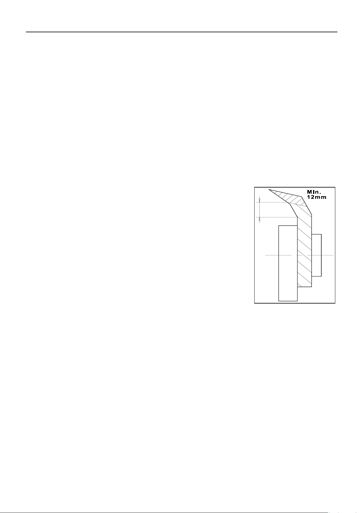
REPLACING WEARING COMPONENTS
Blades, blade bolts and the shearbar are made from high
alloy, heat-treated materials. This heat treatment
produces a particularly hard and tough material capable
of tolerating extreme stress. Damaged blades, blade bolts
or shearbars must be replaced by original KONGSKILDE
spare parts to ensure optimal reliability.
Blades and blade bolts must be checked every day during
the season.
The special blade bolts must be tightened using a torque
wrench to 40 kgm.
The blades must be replaced once they have worn to a
maximum of 8 mm or around 12 mm above the straight
piece (see Fig. 1-4).
Following the replacement of blades and blade bolts, etc., check that no tools have
been left in the machine.
PIGB-206B-02 FCT 1260-1460 0218
- 19 -
3
5
10
12
9
4
6
8
7
STOP
PR80-0821
2 MIN
1
2
3
6
6
7
8
9
10
12
15
14
13
15
6
4
4
5
7
8
7
2
1
13
PR80-0837
15
PR80-0814
14
PR80-0861
11
PR80-0857
1. INTRODUCTION

1. INTRODUCTION
PIGB-206B-02 FCT 1260-1460 0218
- 20 -
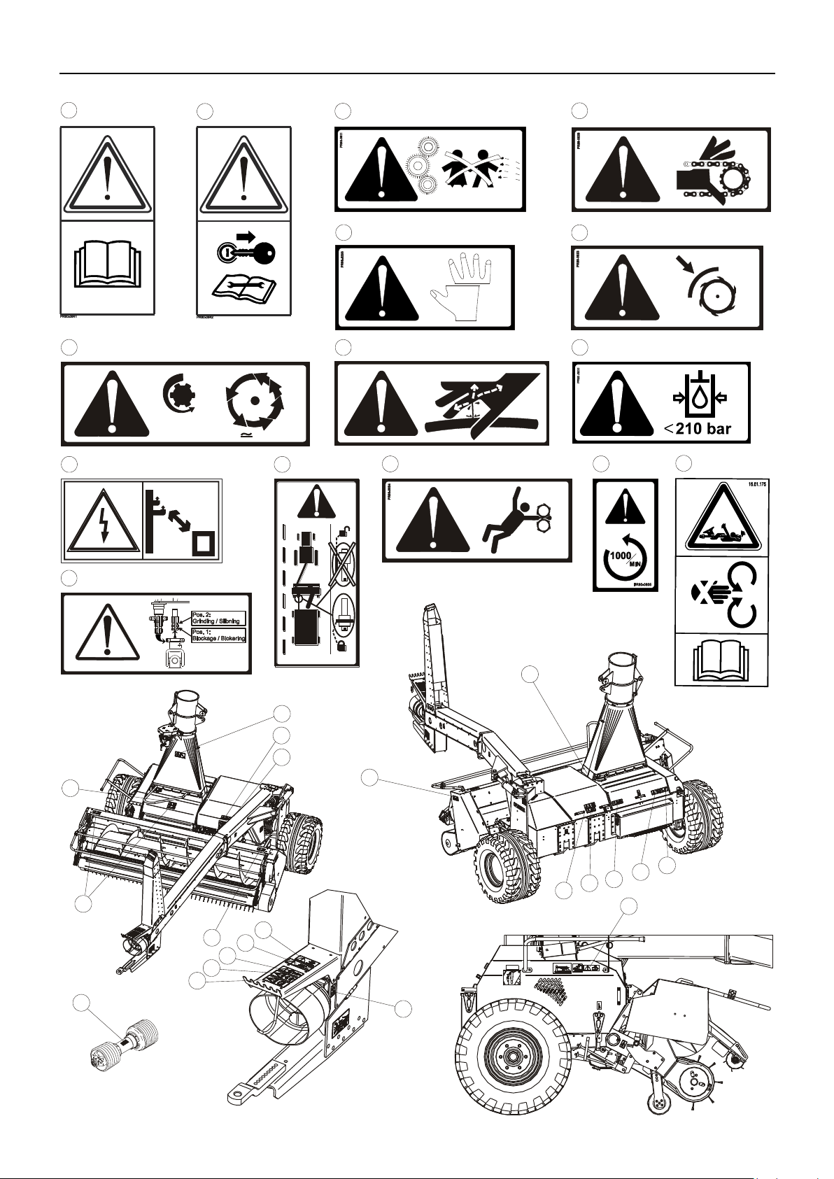
MARKINGS ON THE MACHINE
The warning labels shown on the previous page are positioned as shown on the
drawing at the bottom of the page. Before you start using the machine, ensure that all
labels are present; if not, replace any that are missing. The labels have the following
meaning:
1. Stop the tractor’s engine and remove the ignition key before touching the machine.
Always remember to stop the tractor’s engine before lubricating, adjusting, maintaining or repairing the
machine. Remove the ignition key so that you can be certain no one will start the tractor again until you
have finished.
2. Read the user manual and safety instructions.
This is a reminder that you must read the documents supplied to ensure that you operate the machine
correctly and avoid any unnecessary risk of accidents and mechanical damage.
3. Children.
Never allow children near the machine while it is in operation. Young children in particular have a tendency
to do unpredictable things.
4. Chain drives.
One or several chain drives are located beneath this guard. Ensure that the tractor's engine has been
turned off before opening the guard.
5. Risk of cutting.
There is a risk of fingers, etc. becoming crushed in various parts of the machine. Be careful when the
machine is coupled to the tractor and ready for use. The machine can easily crush or cut off any part of the
body that might get caught in the machine.
6. Remember the guards when grinding.
Remember to close ALL guards after switching to grinding mode before commencing grinding.
7. Rotating parts.
After the tractor's PTO drive shaft has stopped, the blades will have momentum which will keep them
rotating for up to two minutes. Wait until the blades have come to a complete stop before removing guards
for inspection or maintenance.
8. Risk of entanglement.
Keep away from the vicinity of any attachments and feed rollers while the machine running. Ensure that
the tractor's engine has stopped first.
9. RPM and direction of rotation.
Check that the PTO shaft is operating at the correct RPM and rotating in the correct direction. Using an
incorrect RPM and/or direction will damage the machine over time, resulting in a risk of personal injury.
10. PTO drive shaft.
This label is intended to remind you how dangerous the PTO shaft can be if it is not correctly coupled or
protected.
11. Auto-hitch.
Always block the hydraulic hitch using the pin supplied before driving on public roads with a trailer
attached.
12. Max. 210 bar.
Ensure that the hydraulic components are not subject to a pressure greater than the maximum of 210 bar,
as there could be a risk of explosive damage to components. This will result in both yourself and others
being at serious risk of being hit by metal components at high speed or oil under high pressure.
13. PTO drive shaft for rotor.
There is an alternative pin for the PTO drive shaft for the rotor. This is used both when the rotor is
disconnected for reversing and when the rotor rotates in the opposite direction for grinding. Ensure that
you place the PTO shaft correctly on the pin when performing these operations.
14. High-voltage lines.
This label is intended to warn of the danger of getting too close to high-voltage lines with the machine.
15. Hydraulic oil under pressure
Warning against hydraulic oil under pressure.
PIGB-206B-02 FCT 1260-1460 0218
- 21 -
PR11-1810
1. INTRODUCTION

1. INTRODUCTION
PIGB-206B-02 FCT 1260-1460 0218
- 22 -
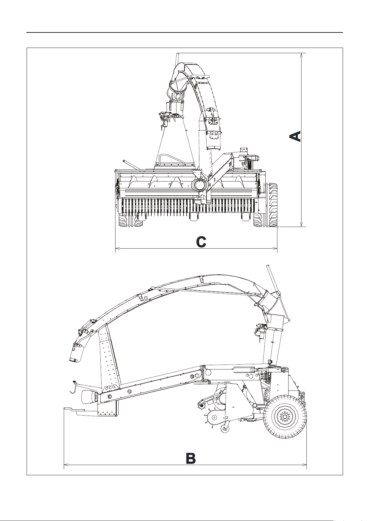
TECHNICAL DATA
FCT 1260
FCT 1260MD
FCT 1460MD
pick-up width
2.65 m
2.65 m
3.1 m
Power requirement
110–206 kW
/ 150-280 HP
110–206 kW
/ 150-280 HP
147–206 kW
/ 200-280 HP
Metal detector
-
Standard
Standard
Width of blade rotor
0.72 m
0.72 m
0.9 m
RPM for rotor
1600 RPM
1600 RPM
1600 RPM
Number of blades
24 / 32
24 / 32
40
Theoretical maximum cutting length
21 / 15 mm
21 / 16 mm
16 mm
Reversible shearbar
Standard
Standard
Standard
Number of feed rollers
4
4
4
Feed reversal
Electro-hydraulic
Electro-hydraulic
Electro-hydraulic
Turning angle for chute
280 degrees
280 degrees
280 degrees
Standard tyre size
13.5/75-430.9
13.5/75-430.9
500/50-17
Tyre size (Accessory)
500/50-17
500/50-17
-
Free-wheeling clutch in PTO shaft
Standard
Standard
Standard
Friction clutch in PTO shaft
3000 Nm
3000 Nm
3000 Nm
Steel wheels on pick-up
3 3 3
Weight with pick-up
3600 kg
3600 kg
3800 kg
Maximum axle load
2950 kg
2950 kg
3050 kg
Maximum length, B
5.31 m
5.31 m
5.31 m
Maximum width
with pick-up, C
Wheels,
Standard
3.0 m
3.0 m
3.57 m
Wheels,
Accessory
3.3 m
3.3 m
-
Transport height,
A
Standard
3.8 m
3.8 m
3.8 m
Parallel operation
4.4 m
4.4 m
4.4 m
Folding chute
3.8 m
3.8 m
3.8 m
Hitch for trailer: drawbar load/
total weight
2,000 kg/
15,000 kg
2,000 kg/
15,000 kg
2,000 kg/
15,000 kg
TECHNICAL DATA

PIGB-206B-02 FCT 1260-1460 0218
- 23 -
2. CONNECTING TO THE TRACTOR
HYDRAULICS
CONNECTING THE HYDRAULICS
DANGER: The hydraulic components must not be exposed to a working
pressure in excess of 210 bar, as a higher working pressure
may gradually cause parts to be damaged. This poses a serious
risk of personal injury.
CAUTION: It is important that the quick-release couplings are always thoroughly
cleaned prior to fitting in order to prevent impurities from penetrating
the hydraulic system and damaging important valve functions. When
the hydraulic hoses are not connected to the tractor, these should be
positioned in the holder at the end of the drawbar.
The machine is equipped with its own hydraulic system, which must be supplied with
oil from the tractor.
The system is used for pick-up lifting, drawbar, chute swivelling, deflector, folding
chute and reverse function. None of these functions uses very much oil and are
controlled in the best way when the oil flow is low. You should therefore set the oil
flow from the tractor to 15-20 l/min., or as low as possible.
Connect the hoses to a double-acting outlet on the tractor, or better still: connect the
pressure hose to the A-port on the hydraulic outlet and the return hose to a vacant
return-port leading directly to the tank or rear-axle assembly. This ensures that the
return pressure is suitably low. This is especially important if the oil flow from the
tractor cannot be adjusted to a sufficiently low level.
IMPORTANT: The hydraulic port for the selected A port must be locked in the
pressure position to ensure a continuous oil flow to the machine's
hydraulic system.
The machine will control the oil pressure and flow itself if it has been fitted with LS.
2. CONNECTING TO THE TRACTOR
2. CONNECTING TO THE TRACTOR
PIGB-206B-02 FCT 1260-1460 0218
- 24 -
PR11-1903
Closed centre
Load Sensing
Open centre
Fig. 2-1
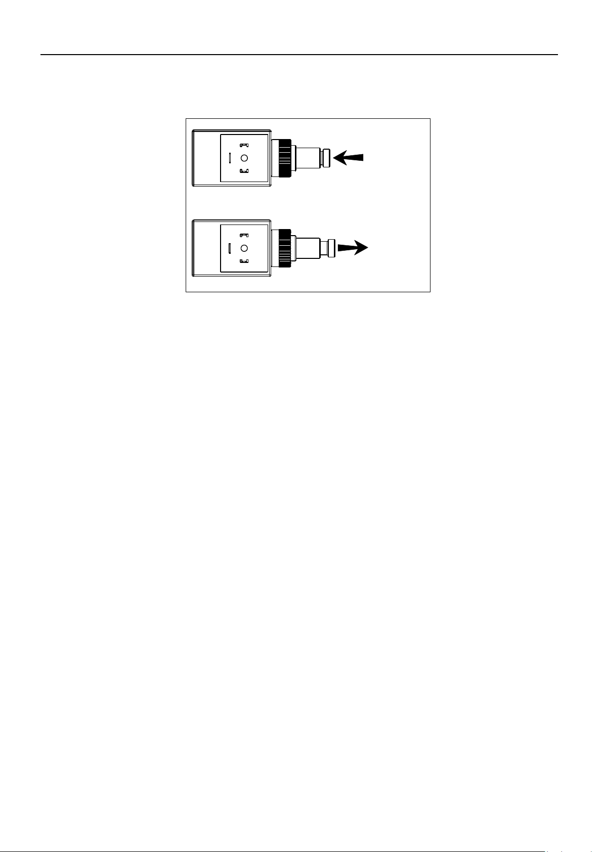
BYPASS VALVE
Fig. 2-1 A distinction is made between two types of tractor hydraulic systems: "open centre
hydraulics" (also known as "fixed pump") and "closed centre hydraulics" (also known
as "variable pump").
If the tractor is of the “open centre" type, the bypass valve must be open to permit
the passage of oil back to the tractor, and will only be activated when a function on
the machine is activated. The valve may be altered using the thumbscrew if it is not
open.
If the tractor is of the “closed centre" type, the bypass valve must be closed to
permit the tractor to close the oil flow automatically when no functions are active. The
valve may be altered using the thumbscrew if it is not closed.
The bypass valve is located on the left hand side of the valve block.
None of the hydraulic functions use more than around 10 litres of oil per minute.
You should therefore set the oil flow from the tractor to 10 l/min. of oil if possible. The
bypass valve has been designed for a maximum of 40 l/min. Pressure loss will occur
if this limit is exceeded, which can cause the temperature of the oil and valves to
increase.
The bypass valve must be set to closed centre if the machine has been fitted with
LS.
2. CONNECTING TO THE TRACTOR
PIGB-206B-02 FCT 1260-1460 0218
- 25 -
PR12-1904
A
A
B
B
Fig. 2-2
ADJUSTMENT OF HYDRAULIC FLOW
The machine may be fitted with a hydraulic block allowing the adjustment of the flow
to the deflector and drawbar.
Fig. 2-2 The adjustment screws A are used to adjust the speed at the drawbar. The
adjustment screws B are used to adjust the deflector. The machine is supplied from
the factory with the flow adjusted to the recommended rate. Slacken the nuts and
turn the adjustment screws to change this. Tighten the nuts again when you are
happy with the level of adjustment.
IMPORTANT: It is possible to adjust the screw to such an extent that the function
works in the opposite way. Unscrew the adjustment screw again until
the function works correctly if this occurs.

2. CONNECTING TO THE TRACTOR
PIGB-206B-02 FCT 1260-1460 0218
- 26 -
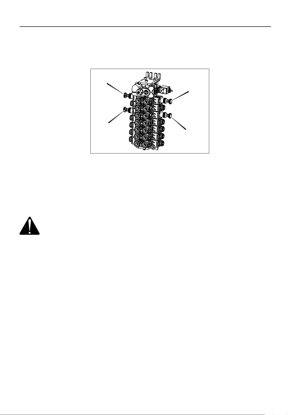
Fig. 2-3
CONNECTING THE ELECTRICAL SYSTEM
Fig. 2-3 The machine is equipped for complete electronic operation of all the machine's
hydraulic functions. The electronic operation consists of two units:
A control unit mounted on the machine together with the hydraulic system.
This unit activates the hydraulic valves;
A control box for operation of the hydraulic functions. This can be beneficially
positioned on the right armrest of the tractor seat for easy access while
working in the field.
The control box is equipped with detachable fittings that can be permanently screwed
into the cab, allowing subsequent dismantling without the use of a tool.
The male connector for the power supply connects to a female connector inside the
tractor cab. This provides 12 V of power and allows a minimum current of 15 A.
Contact your dealer for an adapter if your tractor does not use the same connectors.
IMPORTANT: When parking, position the control box in such a way as to prevent
the ingress of water.
2. CONNECTING TO THE TRACTOR
PIGB-206B-02 FCT 1260-1460 0218
- 27 -
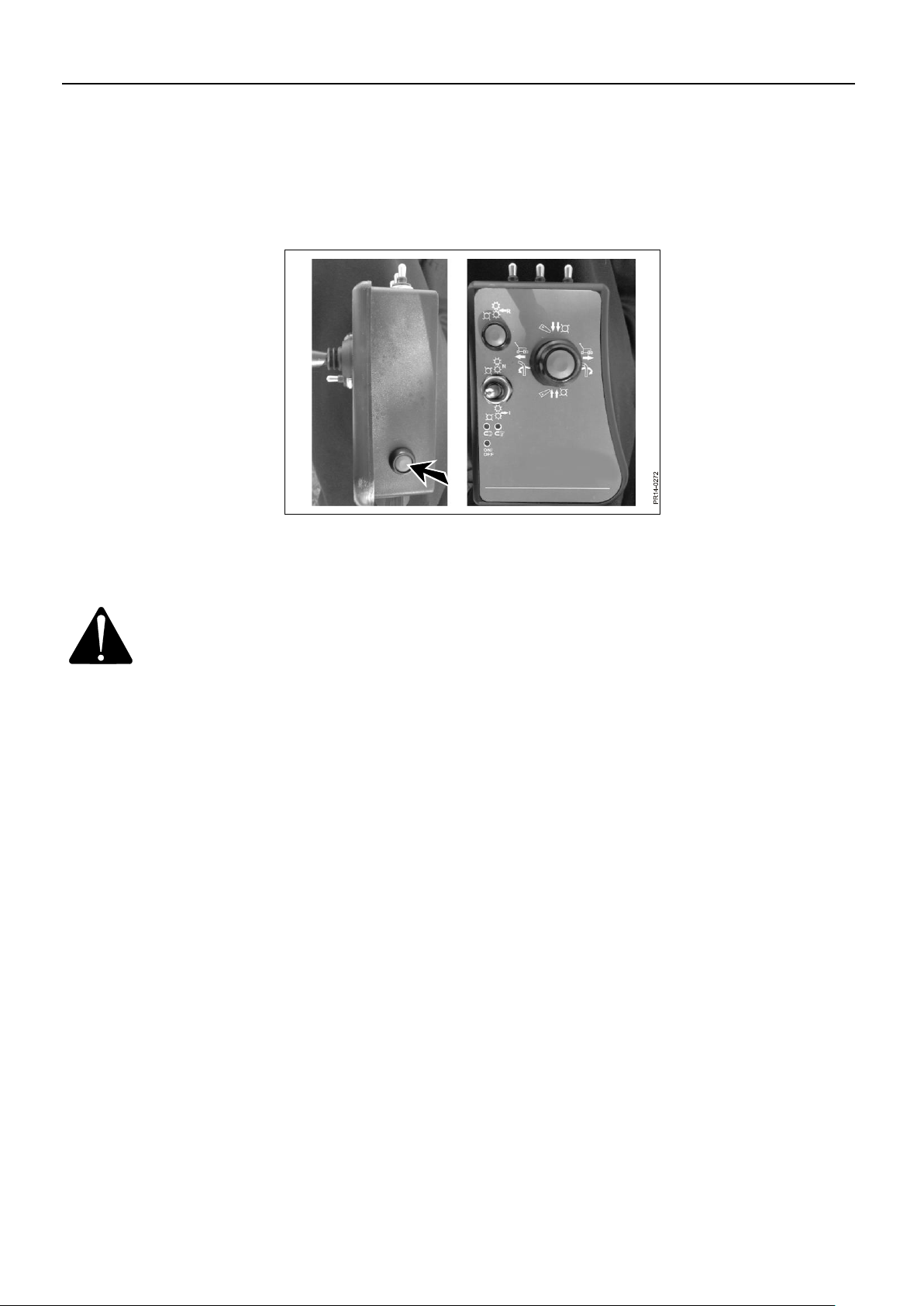
Fig. 2-4
ELECTRO-HYDRAULIC CONTROL
The machine is operated from the control box, which controls the electro-hydraulic
functions.
Fig. 2-4 The control is turned on and off on the side of the control box.
IMPORTANT: Remember to turn off the control box if the tractor is going to be
stopped for some time. Although the machine is not in operation,
several electric coils may be activated. These will drain the tractor’s
battery.

PIGB-206B-02 FCT 1260-1460 0218
- 28 -
FUNCTIONS
Fig. 2-5
Fig. 2-6
Fig. 2-5 On the joystick:
Chute: Push to the left: The chute turns anti-clockwise. Push to the right: The chute
turns clockwise.
Drawbar: While pushing the button: Push to the left: The machine moves behind the
tractor. Push to the right: The machine moves out to the swath.
2. CONNECTING TO THE TRACTOR
Fig. 2-6 On the joystick:
Chute: Push forwards: The deflector points downward. Pull back: The deflector
points upward.
Pick-up: While pushing the button: Push forward: The pick-up is lowered. Pull back:
The pick-up is raised.
It takes around two seconds to lower the pick-up completely so that the supporting
wheels can follow the ground
2. CONNECTING TO THE TRACTOR
PIGB-206B-02 FCT 1260-1460 0218
- 29 -
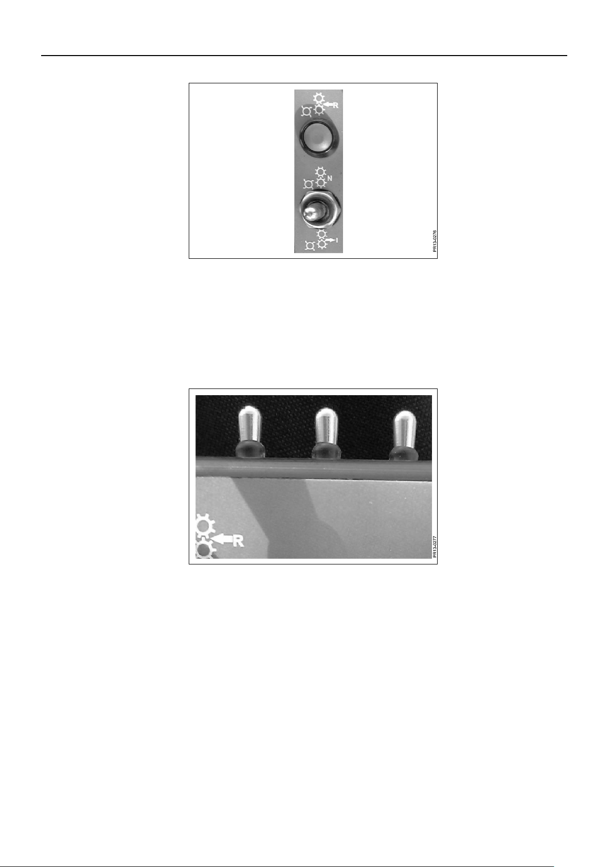
Fig. 2-7
Fig. 2-8
Fig. 2-7 Reverse function. Applies to feed rollers and pick-up.
Feed in: Move the toggle switch to the rear.
Neutral: Move the toggle switch forward for around two seconds and then back to
the centre position. Feed rollers and pick-up stay in neutral position.
Reverse: With the toggle switch in the centre position, you reverse by holding down
the push-button. Reversing will stop when you release the button.
Fig. 2-8 There are three toggle switches at the front of the control box. One of these controls
the folding of the chute, while the other two switches are for accessories. These
switches automatically return to the neutral centre position after being activated.

2. CONNECTING TO THE TRACTOR
PIGB-206B-02 FCT 1260-1460 0218
- 30 -
Fig. 2-9
Fig. 2-10
Control lights
Fig. 2-9 This light will be illuminated when the control unit is switched on.
Fig. 2-10 The control light on the left is illuminated when the metal detector is active. It turns off
when there is a stoppage caused by metal or if the metal detector is turned off.
The control light on the right will illuminate constantly when there is a stoppage
caused by metal. If the light flashes, this indicates that the control box has been
turned off or there is a loose connection with the control box on the tractor.
The metal detector turns on each time the control unit is switched on. If you wish to
turn off the metal detector, this can be done by pushing the button on the MD control
unit on the machine.
Hold the button for about 5 seconds. The control light on the left of the control box
then extinguishes. The control light on the left of the control box will remain
illuminated until the metal detector is turned off.
See also the section: "MD-CONTROL"
 Loading...