

Page 1

ORIGINAL INSTRUCTIONS - according to Directive 2006/42/EC, Annex I 1.7.4.1
OPERATOR’S MANUAL
FCT 1360
Harvester
Part number 81PIGB-186x
1st edition English
February 2018
Page 2

Page 3

PIGB-186X-05 FCT1360 0218
- 3 -
FOREWORD
DEAR CUSTOMER!
We appreciate the confidence you have shown to our company by investing in a
KONGSKILDE product and congratulate you with your new purchase. Of course, it is
our wish that you will experience complete satisfaction with the investment.
This instruction manual contains information about correct and safe use of the
machine.
When buying the machine you will receive information about use, adjustment and
maintenance.
However, this first introduction cannot replace a more thorough knowledge of the
different tasks, functions and correct technical use of the machine.
Therefore you should read this instruction manual very carefully before using
the machine. Pay special attention to the safety instructions.
This instruction manual is made so that the information is mentioned in the order you
will need it, i.e. from the necessary operation conditions to use and maintenance.
Besides this there are illustrations with text.
"Right" and "Left" are defined from a position behind the machine facing the direction
of travel.
All the information, illustrations and technical specifications in this instruction manual
describe the latest version at the time of publication.
Kongskilde Industries A/S reserves the right to make changes or improvements in the
design or construction of any part without incurring the obligations to install such
changes on any unit previously delivered.
Page 4

PIGB-186X-05 FCT1360 0218
- 4 -
CONTENTS
FOREWORD ....................................................................................................................... 3
CONTENTS ......................................................................................................................... 4
INTRODUCTION ................................................................................................................. 6
INTENDED USE ................................................................................................. 6
PERFORMANCE ................................................................................................ 7
SAFETY .............................................................................................................. 9
Definitions .............................................................................................. 9
General safety instructions ................................................................... 10
Locking of guards ................................................................................. 11
Choice of tractor ................................................................................... 12
Connection and disconnection ............................................................. 12
Adjustment ........................................................................................... 13
Transport .............................................................................................. 14
Working ................................................................................................ 15
Parking ................................................................................................. 15
Greasing .............................................................................................. 15
Grinding ............................................................................................... 16
Maintenance ........................................................................................ 17
Replacement of wearing parts ............................................................. 17
Safety decals ....................................................................................... 19
TECHNICAL DATA ........................................................................................... 21
2. CONNECTION TO TRACTOR ...................................................................................... 22
THE HYDRAULIC SYSTEM ............................................................................. 22
Hydraulic connection ............................................................................ 22
Bypass valve ........................................................................................ 23
Connection of electric system .............................................................. 24
ELECTRO-HYDRAULIC CONTROL ................................................................ 25
Functions ............................................................................................. 26
DRAWBAR AND PTO DRIVE SHAFT .............................................................. 29
Shortening of the PTO drive shaft ........................................................ 31
Friction clutch ....................................................................................... 31
3. MOUNTING OF EQUIPMENT ....................................................................................... 32
HITCH FOR TRAILER ...................................................................................... 32
Combi-hitch .......................................................................................... 32
Hydraulic hitch hook (Auto-hitch) ......................................................... 33
PICK-UP ........................................................................................................... 34
TRANSPORT CONVERSION .......................................................................... 37
FITTING CHUTES ................................ ............................................................ 38
Chute turning ....................................................................................... 38
Standard chute ..................................................................................... 40
Foldable chute ..................................................................................... 40
Chute for parallel operation .................................................................. 41
LIGHTING KIT .................................................................................................. 43
Page 5

PIGB-186X-05 FCT1360 0218
- 5 -
4. ADJUSTMENTS ............................................................................................................ 45
PICK-UP ........................................................................................................... 45
OPENING OF ROTOR HOUSING.................................................................... 46
Collapsible chute .................................................................................. 49
ROTOR AND ROLLER SECTION .................................................................... 52
CUTTING LENGTHS ........................................................................................ 56
REPLACEMENT AND ADJUSTMENT OF BLADES ........................................ 57
GRINDING ........................................................................................................ 59
Grinding operation ............................................................................... 60
Rough grinding ..................................................................................... 62
REVERSE ........................................................................................................ 63
NEUTRAL POSITION ....................................................................................... 65
5. WORKING IN THE FIELD ............................................................................................. 66
GENERAL CONDITIONS ................................................................................. 66
Swathing before chopping .................................................................... 66
TRANSPORT POSITION ................................................................................. 67
STARTING IN THE FIELD ................................................................................ 68
Blockage in the machine ...................................................................... 69
After work ............................................................................................. 71
MISCELLANEOUS ........................................................................................... 71
WORKING POSITIONS .................................................................................... 71
6. MAINTENANCE ............................................................................................................ 73
IN GENERAL .................................................................................................... 73
GUARDS .......................................................................................................... 74
REPLACEMENT OF BLADES .......................................................................... 74
TYRE PRESSURE ........................................................................................... 75
FRICTION CLUTCH ......................................................................................... 76
FUSES .............................................................................................................. 79
MISCELLANEOUS ........................................................................................... 80
Rollers .................................................................................................. 80
Chain tightener for pick-up auger ......................................................... 80
7. GREASING ................................................................................................................... 81
Oil in gearboxes ................................................................................... 89
8. STORAGE (WINTER STORAGE) ................................................................................. 91
9. SPARE PARTS ORDER ............................................................................................... 92
10. MACHINE DISPOSAL ................................................................................................. 93
11. MISCELLANEOUS ..................................................................................................... 94
HYDRAULIC DIAGRAM FOR FCT 1360 .......................................................... 94
CONTROL SYSTEM ........................................................................................ 94
CONTROL BOX................................................................................................ 95
CONTROL UNIT ON THE MACHINE ............................................................... 97
CONTROL UNIT ON MACHINE, WIRING SYSTEM ........................................ 98
12. WARRANTY ................................................................................................................ 99
Page 6

1. INTRODUCTION
PIGB-186X-05 FCT1360 0218
- 6 -
INTRODUCTION
INTENDED USE
The precision chop forage harvester FCT 1360 is solely constructed and
manufactured for the usual work in agriculture, i.e.: Usual work in fields where
you want to cut/gather and chop green crops such as maize, grass or whole crop
which are to be used for silage production intended for coarse fodder for cattle.
The machine should only be connected to a tractor which corresponds with the
specifications of the product and is legal to use.
Any use beyond this is outside the intended use. Kongskilde Industries A/S is
not responsible for any damage resulting from such use, the user bears that
risk.
It is assumed that the work is performed under reasonable conditions, i.e. that the
fields are cultivated normally and to a reasonable extent kept clear of foreign matter
and the like.
Intended use also means that the instructions given by Kongskilde Industries A/S in
the instruction manual and the spare parts book are observed and that thorough
agricultural knowledge and technically correct use is a matter of course.
The precision chop forage harvester FCT 1360 should only be used, maintained
and repaired by persons who, through relevant instructions and after reading
the instruction manual, are familiar with the machine and, in particular, are
informed of possible dangers.
In the following there are a number of general and special safety instructions which
must be observed altogether.
If changes are made on the machine and its construction without permission from
Kongskilde Industries A/S, Kongskilde Industries A/S cannot be held responsible for
any damage resulting from this.
Page 7

1. INTRODUCTION
PIGB-186X-05 FCT1360 0218
- 7 -
Dry matter
Capacity
Dry matter
100%
18 ton/h
Wet new grass
15%
120 ton/h
Not pre-dried grass
18%
100 ton/h
Pre-dried grass – no outflow of sap from clamp
silo
25%
72 ton/h
Pre-dried grass – no outflow of sap from high
tower silo
33%
55 ton/h
Very pre-dried grass
50%
36 ton/h
Straw, very dry
90%
20 ton/h
PERFORMANCE
The precision chop forage harvester FCT 1360 has a very versatile use which, with
the right equipment, makes it possible to chop grass, maize and whole crops. At the
same time FCT 1360 is capable of working alone or parallel with other machines.
FCT 1360 has a high capacity compared with other corresponding products as it
uses the “DIRECT CUT” system. “DIRECT CUT” gives a minimum loss of power
when cutting the material and thus ensures maximum utilisation of the accessible
tractor power.
Capacity, however, is difficult to define and compare as, for a forage harvester, it will
depend not just on which crop is being cut but also how the crop has been treated
before it is picked up or cut by the machine and finally which cutting length
adjustment the machine is working with.
If we take a forage harvester which, in fresh, not pre-dried grass, can work 100 tons
per hour, it is possible to calculate the capacity at different per cents of dry matter
depending on the pre-treatment before cutting, as shown in the following table.
It will probably surprise most people that the capacity can vary between 20 and 120
ton/h, as a result of varying water content.
In practice you want to drive the forage harvester in the highest possible tractor gear
without causing frequent blockage. However, the amount of grass in the field will
always vary, for instance where the mower conditioner has had to turn, change
forward speed or change direction of travel. Therefore it is often appropriate either to
drive with a power reserve so that the machine will not block, or to continuously
adapt the driving of the forage harvester to the conditions.
Page 8

1. INTRODUCTION
PIGB-186X-05 FCT1360 0218
- 8 -
The pick-up unit and the feed rollers are both secured against overloading. The pickup unit is secured by a friction clutch, the feed rollers by a shear bolt clutch. The
forage harvester also has a reverse function which makes it possible to remove a
blockage without having to leave the tractor seat.
The intention is that the inexperienced user increases the forward speed gradually in
the beginning until the pick-up is blocked; releases the blockage again by reversing
and chooses a tractor gear at a suitable lower level to remove the risk of blockage.
However, it is not the intention that the clutch function of the feed rollers releases. If
this happens, the clutch adjustment of the pick-up must be reduced. The same will
apply if the main friction clutch between the tractor and the machine releases during
normal working. If it is not the pick-up unit which is blocked, the adjustment of the
machine is incorrect.
Unfortunately it has been seen that the torque adjustment of the friction clutch of the
pick-up unit has been increased to the point where it is the friction clutch between the
machine and the tractor which releases frequently. The main friction clutch is not
intended to release frequently but only for starting shock or when foreign matter gets
into the machine. The same applies to the shear bolt clutch for the feed intake rollers.
The main clutch simply cannot absorb the heat which is generated during these long
releases. The power transmitted at the main clutch will be at least 10 times higher
than the power needed to drive the pick-up unit.
Only the pick-up unit can be seen from the tractor and therefore it should be released
first when there is a blockage. The experienced user will be able to adapt the driving
of the tractor to the amount of grass and thus work with less capacity reserve and, all
other things being equal, have a greater output.
The cutting length of the forage harvester can be adjusted and adapted to the crop in
question. The cutting length is usually reduced when cutting maize and whole crops
to ensure greater damage of the grains. The shorter cutting length will of course
require more power for which reason there will be a lower output when cutting maize
and whole crop than when cutting grass, though it is difficult to compare.
The power requirements are also increased when the blades are worn and the
shearbar adjustment thereby changes. It is necessary to sharpen the blades and
adjust the shearbar during the season.
Page 9

1. INTRODUCTION
PIGB-186X-05 FCT1360 0218
- 9 -
SAFETY
The safety of persons and machines is an integral part of Kongskilde’s development
work. We wish to ensure the safety of you and your family in the best possible
way, but this also requires and effort on your part. However, damage can occur as a
consequence of misuse and insufficient instruction.
A forage harvester cannot be constructed in such a way that it guarantees the full
safety of persons and at the same time performs an efficient piece of work. This
means that it is very important that you as user of the machine pay attention and use
the machine correctly and thereby avoid exposing yourself and others to
unnecessary danger.
As already mentioned the machine is only intended for one purpose, namely:
Chopping of grass and similar green crops, for feeding purposes.
It is assumed that the work is performed under reasonable conditions, i.e. that the
fields are cultivated normally and to a reasonable extent kept clear of foreign matter
and the like.
The machine demands skilled operation, which means that you should read the
instruction manual before you connect the machine to the tractor. Even though
you have been driving a similar machine before, you should read the manuals - this
is a matter of your own safety!
You should never leave the machine to others before you have made sure that they
have the necessary knowledge.
DEFINITIONS
The safety decals and the instruction manual of the machine contain a line of safety
notes. The safety notes mention certain measures, which we recommend you and
your colleagues to follow as to increase the personal safety as much as possible.
We recommend that you take the necessary time to read the safety instructions and
inform your staff to do the same.
In this instruction manual this symbol is used with reference to
personal safety directly or indirectly through maintenance of the
machine.
CAUTION: The word CAUTION is used to ensure that the operator follows the
general safety instructions or the measures mentioned in the
instruction manual to protect the operator and others against injuries.
WARNING: The word WARNING is used to warn against visible or hidden risks,
which might lead to serious personal injuries.
DANGER: The word DANGER is used to indicate measures which, according to
legislation, must be followed to protect oneself and others against
serious injuries.
Page 10

1. INTRODUCTION
PIGB-186X-05 FCT1360 0218
- 10 -
GENERAL SAFETY INSTRUCTIONS
The following is a brief description of the measures, which should be a matter of
common knowledge to the operator.
1. Always disengage the PTO drive shaft, activate the parking brake of the tractor,
stop the tractor engine and remove the ignition key before you:
- lubricate the machine,
- clean the machine,
- disassemble any part of the machine,
- adjust the machine.
2. Always block the wheels before working under the machine.
3. Never start the tractor until all persons are safely away from the machine.
4. Make sure that all tools have been removed from the machine before starting
the tractor.
5. Make sure that all guards have been mounted correctly.
6. During work never wear loose clothes or have your hair hang down as it may be
pulled in by the moving parts of the machine.
7. Always wear suitable shoes to avoid falling.
8. Do not change the guards or work with the machine when a guard is missing or
defective.
9. Always drive with the statutory lights and safety marking during transport on
public road and at night.
10. Limit the transport speed to maximum 30 km/h if the machine has not been
marked with another maximum speed limit.
11. Do not stand near the machine while it is working.
12. When mounting the PTO drive shaft check that the number and direction of
RPM of the tractor matches those of the machine.
13. Always use hearing protectors if the noise from the machine is annoying or if
you are working with the machine for a considerable period in a tractor cabin,
which has not been silenced sufficiently.
14. Never allow anybody to be on the machine during work or transport.
Page 11
1. INTRODUCTION
PIGB-186X-05 FCT1360 0218
- 11 -
Fig. 1-1
P
R
1
1
-
0
2
4
3
PR80-0819
Guard
Fig. 1-2
PR11-0244
PR80-0820
Guard
15. Never use the machine for other purposes than what it has been constructed
for.
16. Do not allow any children to be near when you are working with the machine.
17. Never stand between the tractor and the machine during connection and
disconnection.
18. Do not feed material into the cutting unit, using hands or feet, while it is working.
19. Do not try to remove material from the cutting unit while it is working.
20. If material must be removed from the forage harvester, the PTO shaft must be
disconnected completely. Stop the engine and remove the ignition key.
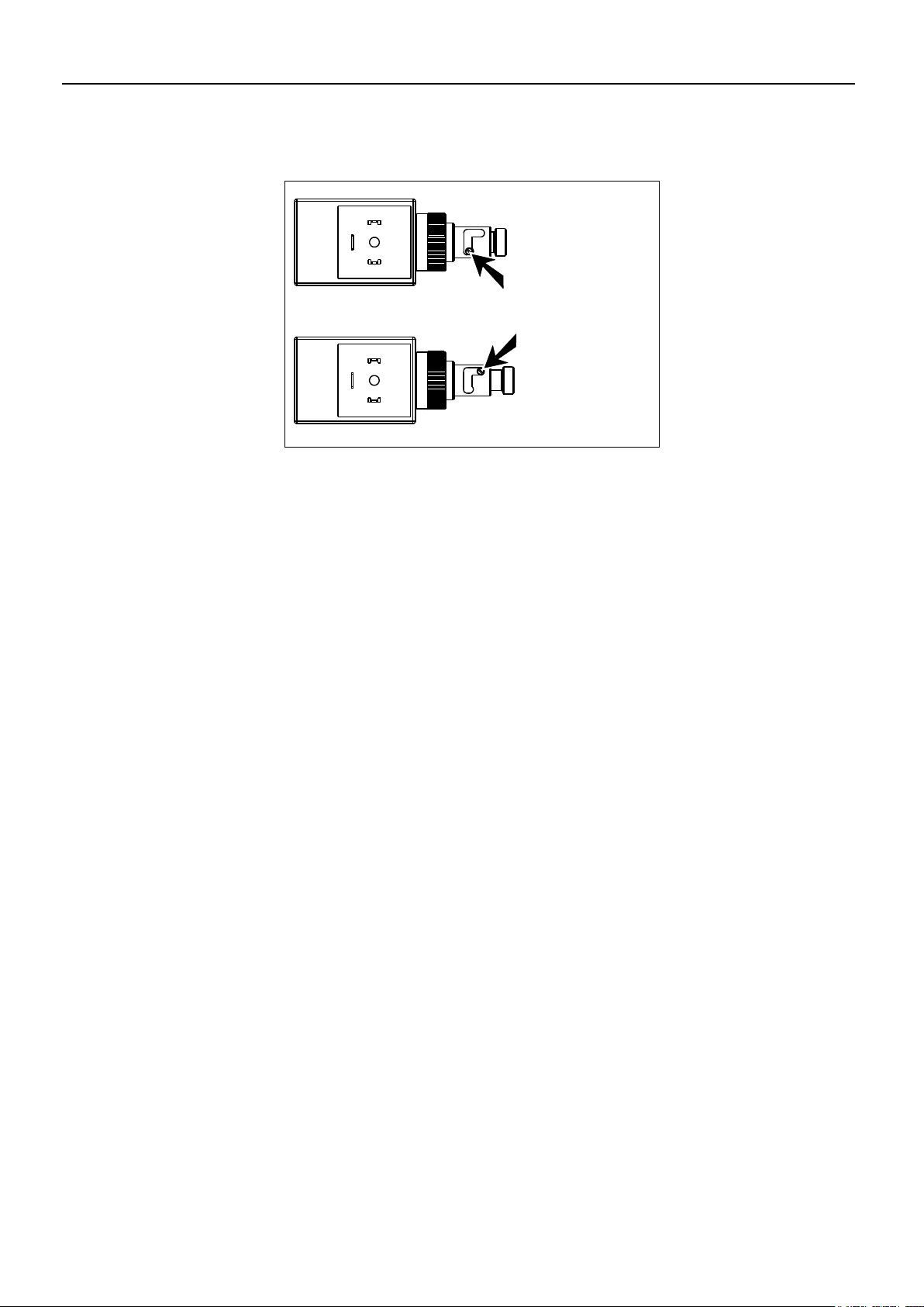
LOCKING OF GUARDS
All hinged guards on the machine are equipped with a lock. The lock ensures that the
guard cannot be opened without tools. There are two different types of lock. Fig. 1-1
and 1-2 show the two locking principles and the corresponding transfers which
indicate and illustrate the locks on the machine.
Page 12

1. INTRODUCTION
PIGB-186X-05 FCT1360 0218
- 12 -
Fig. 1-3
CHOICE OF TRACTOR
Always follow the recommendations specified in the instruction manual of the tractor.
If this is not possible, technical assistance must be sought.
Legal transport of the machine on public road requires a tractor with sufficient mass
and braking capacity.
Choose a tractor which has minimum 103 KW/140 HP at the power take-off but
cannot deliver more than 165 KW/225 HP.
The machine is as standard constructed for 1000 RPM, and is delivered from the
factory with 1 3/4" PTO drive shaft with 20 splines yoke. As an alternative 1 3/4’’
yokes with 6 splines, 1 3/8” yokes with 6 splines and finally 1 3/8” yokes with 21
splines can be supplied for the PTO drive shaft of the machine
A suitable tractor will have a broad range of gears for driving speeds between 5 and
8 km/h.
The tractor hydraulic system should deliver at least 170 bar and the tractor’s
pressure relief valve should not allow more than 210 bar.
The drawbar of the forage harvester is delivered with a drawing eye, for which reason
the tractor should preferably have a clevis drawbar. The drawbar pin should be 30
mm diameter.
Always choose a tractor with a closed cabin when working with a precision chopper.
CONNECTION AND DISCONNECTION
Always make sure that nobody is standing between
the tractor and the machine during connection and
disconnection. An unintentional manoeuvre with the
tractor may cause serious injury (see Fig. 1-3).
When disconnecting it is important that the ground
is even and stable so that the machine does not
move and injure persons or cause damage to other
equipment.
The same precautions must be taken when connecting/disconnecting trailers by
means of the hydraulic hitch at the rear of the forage harvester.
Check that the machine is intended for the number and the direction of rotation of the
tractor PTO. A wrong number of rotations over a long period may damage the
machine and at worst result in ejection of parts through the delivery chute.
Page 13
1. INTRODUCTION
PIGB-186X-05 FCT1360 0218
- 13 -
Fig. 1-4
Make sure that the PTO drive shaft has been mounted correctly, i.e. that the lock pin
is in mesh and that the support chain has been fastened at both ends.
The PTO drive shaft must be correctly protected. If the guard is damaged it must be
replaced immediately.
IMPORTANT: Before connecting the trailer with the hydraulic hitch, always:
- Disengage the PTO from the tractor.
- Wait until all moving parts have stopped.
Check that all hydraulic couplings are tight and that all hoses and fittings are
undamaged before activating the hydraulic system.
Make sure that there is no pressure in the hydraulic hoses when these are
disconnected from the tractor.
Hydraulic oil under pressure can penetrate the skin
and cause serious infections. You should always
protect the skin and the eyes against oil splashes.
(see figure 1-4). If, by accident, hydraulic oil under
pressure hits you, consult a doctor immediately.
ADJUSTMENT
IMPORTANT: Before adjusting the machine, always:
- Disengage the PTO from the tractor.
- Stop the tractor engine
- Wait until all moving parts have stopped.
It is important not to remove the guards until all revolving parts have stopped. This
especially applies to the delivery chute above the blade cylinder.
If the cutting parts in the blade cylinder must be adjusted or replaced, it is important
to block the blade cylinder as the sharp blades can easily cause injury.
Before working, check that the feed rollers and the blade cylinder can move freely.
Also check that the blades are intact and without cracks. Damaged blades must be
replaced to prevent them from blocking or damaging the machine and to avoid metal
parts being thrown out from the delivery chute.
Check periodically if blades and blade bolts are worn according to the rules in the
instruction manual.
The first time you use the machine the blades and blade bolts may "bed in". For this
reason you must check and tighten the blade bolts after the first working hour.
Page 14

1. INTRODUCTION
PIGB-186X-05 FCT1360 0218
- 14 -
TRANSPORT
Limit the transport speed to maximum 30 km/h if the machine has not been marked
with another maximum speed limit.
When the machine has been prepared for transport, the control unit must be turned
off on the button at the side of the control box and the oil flow to the machine must be
interrupted. This prevents faulty operation during transport.
DANGER: Never let anyone stand or sit on the machine, especially not when
you are driving.
The machine has equipment for hydraulic conversion to transport position and the
cylinder for this is fitted with a hose breach valve. If there is air in the cylinder during
transport there is a risk that the machine moves to the opposite lane, the bicycle
track or the sidewalk.
IMPORTANT: If the machine is equipped with auto hitch, the mechanical lock on
the auto hitch must be activated when driving with a trailed wagon on
public road. This also applies if a hose breach valve is fitted on the
lifting cylinder of the auto hitch.
IMPORTANT: To ensure all the air has been expelled from the oil in the hydraulic
cylinders, test all the functions after the hydraulic connections are
connected to the tractor. Especially before you enter or drive on
public roads.
The attachments of the forage harvester (pick-up etc.) must be secured mechanically
before transport.
The statutory lighting and traffic markings must be placed correctly, on the forage
harvester as well as the trailer.
Reflectors and lighting must be cleaned regularly.
Page 15

1. INTRODUCTION
PIGB-186X-05 FCT1360 0218
- 15 -
WORKING
Before you start working make sure that no persons are behind the forage harvester
due to the danger of being hit by metal parts from damaged blades.
Also make sure that there are no persons in the trailer used for picking up. There is
danger of suffocating in the flow of material or getting hit by metal parts.
If the feed rollers or the blade cylinder are blocked, disengage the clutches and stop
the tractor engine immediately. Activate the parking brake and wait until the revolving
parts have stopped before removing the material or the foreign matter.
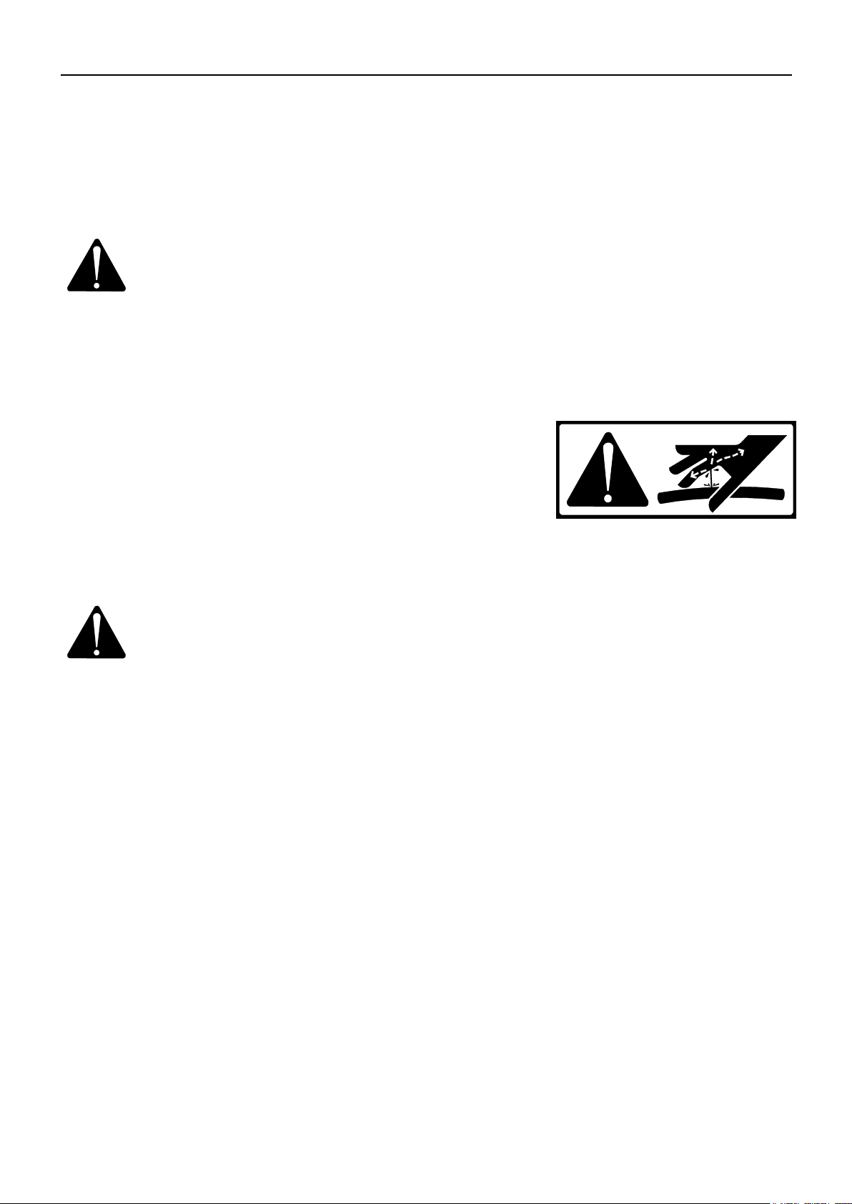
WARNING: This cannot be said often enough: Never remove material blocked in
the machine while the machine is running and never feed material
into the pick-up with your hands or feet as there is a serious danger
of getting caught and pulled into the harvester which would cause
dismemberment or death.
Never allow anyone to stand near the forage harvester while it is working, especially
not children who do not know the danger and do unforeseen things.
The chute is over 4 m high. Be aware of high-voltage lines and keep a safe distance
to these.
PARKING
Before parking the machine always lock the jack with the locking pin, otherwise the
machine may tip over during parking. Also remember to block the wheels if there is a
risk that the machine will move after parking
Remember to remove the hydraulic hoses and the control box before driving away
with the tractor.
GREASING
When greasing or maintaining the machine never let more than one person work at
the machine at a time. This reduces the risk of getting fingers caught because
another person by accident turns the revolving parts while you are still working with
them.
Never try to clean, grease or adjust the machine before the PTO has been
disengaged, the tractor engine has stopped and the parking brake been activated.
Remove the ignition key!
Page 16

1. INTRODUCTION
PIGB-186X-05 FCT1360 0218
- 16 -
GRINDING
When grinding always follow this procedure:
- Stop the tractor engine and remove the ignition key.
- Activate the parking brake.
- Wait until all moving parts have stopped.
Unfortunately it is necessary to remove some of the guards to change the direction of
rotation of the rotor when grinding the blades. As there are chain and belt
transmissions your hands may be injured if the revolving parts have not stopped
before the guards are removed.
Grinding is performed according to the following procedure:
1. Check if the grindstone is undamaged and if the device is able to move back
and forth easily.
2. Lower the guard behind the grinding device to give access to the blade cylinder.
3. Adjust the stone and guard the grinding device again.
4. Remove the guard above the blade cylinder transmission and change the
direction of rotation of the rotor.
5. Close the guard again and check that there are no persons near the machine.
6. Start the tractor again and keep the rpm at idle speed or a little above.
7. Perform the grinding carefully.
Always use safety glasses when grinding as small particles from the grindstone might
hit you.
When grinding has finished, stop the tractor engine, remove the ignition key, change
the direction of rotation and fasten all guards.
REMEMBER: Always grind with all guards closed.
Page 17
1. INTRODUCTION
PIGB-186X-05 FCT1360 0218
- 17 -
Fig. 1-5
MAINTENANCE
After approx. 2 days of operation, all bolts should be re-tightened. Always make sure
that the used spare parts are tightened to the correct torque.
When replacing parts in the hydraulic system always make sure that the pick-up rests
on the ground and/or the lifting cylinders are blocked.
Hydraulic hoses must be checked by an expert before use, and after that minimum
once a year. If necessary, they must be replaced. The working life of hydraulic hoses
should not exceed 6 years, including maximum 2 years of storage.
When replacing, always use hoses which comply with the requirements stated by the
manufacturer. All hoses are marked with date of production.
REPLACEMENT OF WEARING PARTS
Blades, blade bolts and shearbar are made of highalloyed, heat-treated materials. This heat treatment
provides especially hard and ductile material which is able
to withstand extreme stress. Damaged blades, blade bolts
or shearbars must be replaced by original KONGSKILDE
spare parts to ensure safe operation.
Blades and blade bolts must be checked every day during
the season.
The special blade bolts must be tightened with a torque
wrench to 40 kgm.
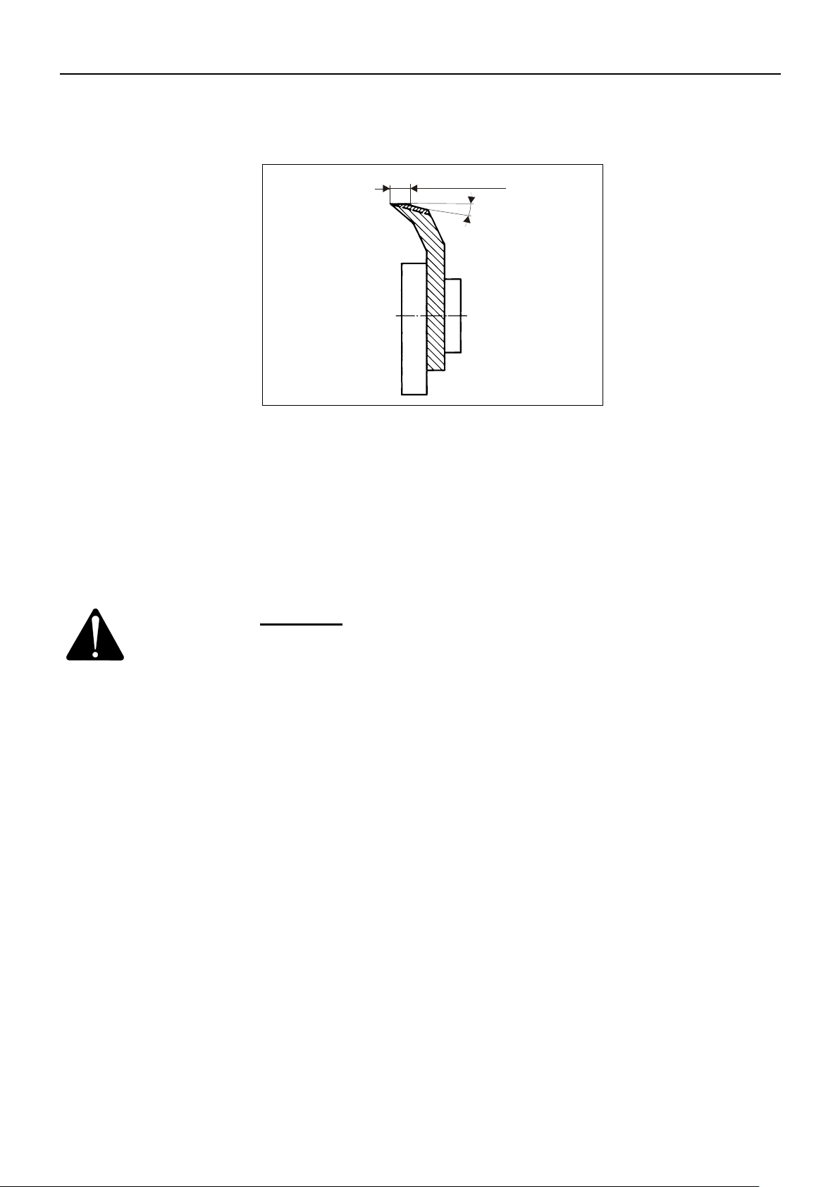
When the blades have been worn max. 8 mm or approx.
12 mm above the straight piece, they must be replaced
(see fig. 1-5).
After replacement of blades, blade bolts and the like, check that no tools have been
left in the machine.
Page 18
PIGB-186X-05 FCT1360 0218
- 18 -
3
5
10
12
9
4
6
8
7
STOP
PR80-0821
2 MIN
1
2
3
6
7
7
8
9
10
12
15
14
13
15
6
4
5
7
5
8
7
2
1
13
PR80-0837
15
PR80-0814
14
PR80-0861
11
PR80-0857
1. INTRODUCTION
Page 19

1. INTRODUCTION
PIGB-186X-05 FCT1360 0218
- 19 -
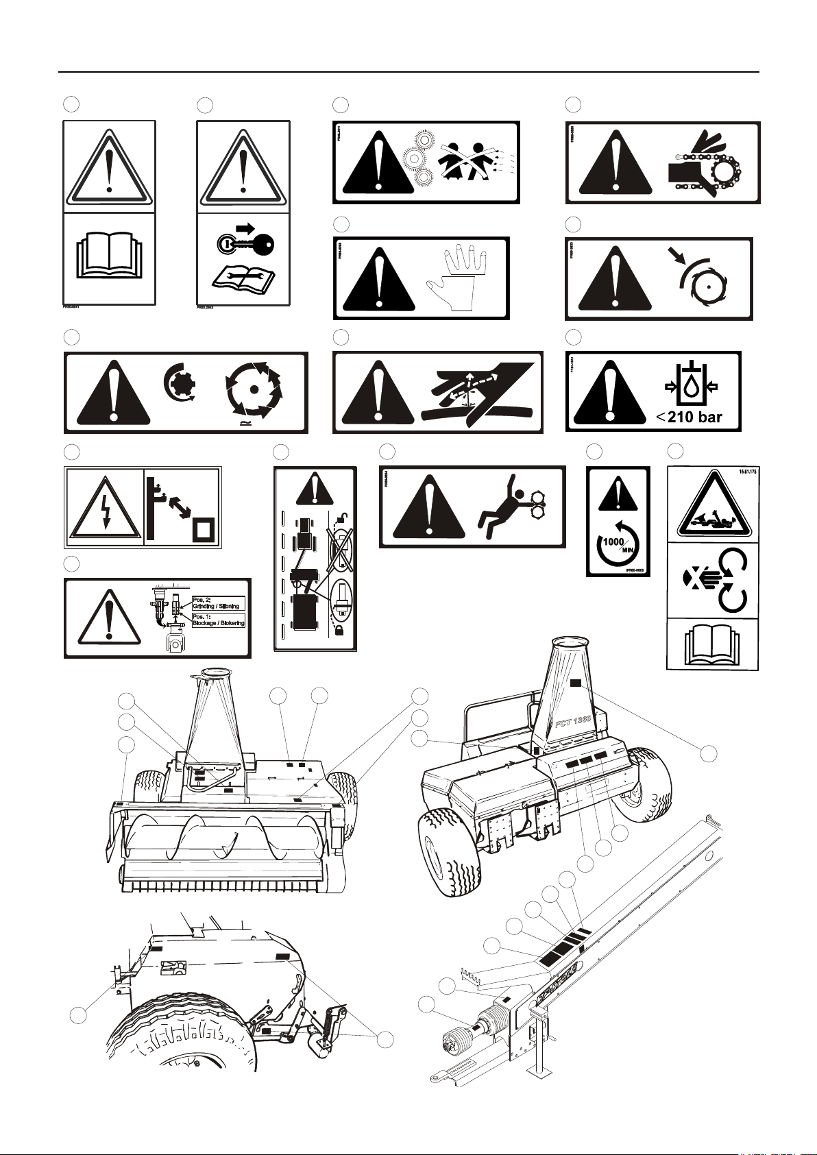
SAFETY DECALS
The safety decals shown on the previous page are positioned as shown on the
drawings. Before using the machine, check that all decals are present: if not, require
those missing. The decals have the following meaning:
1. Stop the tractor engine and remove the ignition key before touching the machine.
Always remember to stop the tractor engine before lubricating, adjusting, maintaining or repairing. Also
remember to remove the ignition key to ensure that nobody starts the engine until you have finished.
2. Read the instruction manual and the safety instructions.
This is to remind you to read the delivered documents to ensure the machine is operated correctly and to
avoid unnecessary accidents and machine damage.
3. Children.
Never let children stand near the machine during operation. Especially not small children as they have a
tendency to do unforeseen things.
4. Chain drive
One or more chain drives are placed under this guard. Make sure that the tractor engine has stopped
before opening the guard.
5. Risk of cutting.
There is a risk of getting fingers etc. caught several places on the machine. Be careful when the machine
is connected to the tractor and ready to work. The machine can easily crush or cut off any part of the body
that might get caught in the machine.
6. Remember the guards when grinding.
Remember to close ALL guards before grinding.
7. Rotating parts.
After the PTO drive shaft has stopped, the blades will have a momentum where they keep rotating for up
to 2 minutes. Wait until the blades have come to a complete stop before removing guards for inspection or
maintenance.
8. Risk of getting pulled into the machine.
Do not stand near the attachments or the feed rollers while the machine is running. Make sure that the
tractor engine has stopped first.
9. The number and the direction of rotations.
Check that the PTO drive shaft runs with the right RPM and in the right direction. A wrong number of
rotations and/or direction of rotation can damage the machine with the risk of personal injury as a result.
10. The PTO drive shaft.
This decal has the purpose to remind you how dangerous the PTO drive shaft can be if it is not correctly
mounted or protected.
11. Auto hitch.
Always block the hydraulic hitch with the supplied pin before driving with a trailed wagon on public road.
12. Maximum 210 bar.
Make sure that the hydraulic components are not exposed to more pressure than maximum 210 bar as
there could be a risk of explosive damage of parts. Hereby you expose yourself and others to serious
danger of getting hit by metal parts with high speed or oil under high pressure.
13. PTO drive shaft for rotor.
There is an alternative pin for the PTO drive shaft for the rotor. It is used when the rotor is disconnected
during reverse and when the rotor rotates in the opposite direction during grinding. Make sure that you
place the PTO drive shaft correctly on the pin when performing these operations.
14. High-voltage lines.
This decal has the purpose to remind you of the danger of getting too close to high-voltage lines.
15. Hydraulic oil under pressure.
Warning against hydraulic oil under pressure.
Page 20

PIGB-186X-05 FCT1360 0218
- 20 -
PR11-1746
5232
3569
3395
1. INTRODUCTION
Page 21

1. INTRODUCTION
PIGB-186X-05 FCT1360 0218
- 21 -
TECHNICAL DATA
FCT 1360
Pick-up width
3.1 m
Power requirement
103–165 kW/140-225 HP
Capacity (*)
35 - 100 t/hour
Blade rotor width
0.9 m
Rpm for rotor
1600 rpm
Number of blades, standard
40
HD blades
Standard
Grinding device
Grindstone with quick adjustment
Reverse grinding
Standard
Theoretical cutting length, standard
7 and 15mm
Reversible shearbar, tungsten-coated
Standard
Number of feed rollers
4
Reverse of feed intake
Standard, hydraulic
Hydraulic functions
Pick-up lifting, drawbar, chute swivelling,
deflector and reverse function
Turning angle for chute
260 degrees
Pick-up, pre-lubricated
Standard
Weight with pick-up
2995kg
Maximum length
5.2 m
Maximum width with pick-up
3.57 m
Transport height
3.4 m
Tyre dimension standard
19/45 x 17
Freewheeling clutch in PTO shaft
Standard
Friction clutch in PTO shaft
Standard, 3000 Nm
Steel wheels on pick-up
Standard
Rubber wheels on pick-up
Option (width 3.63 m)
Hydraulic Auto-Hitch
Option
Hitch for trailer: drawbar load/ total
weight
2000kg/ 15000kg
TECHNICAL DATA
(*) Depends on dry matter content, cutting length, the condition and the amount of crop.
We reserve the right to change the construction and specification details without
notice.
Page 22

PIGB-186X-05 FCT1360 0218
- 22 -
2. CONNECTION TO TRACTOR
THE HYDRAULIC SYSTEM
HYDRAULIC CONNECTION
DANGER: The hydraulic components must not be exposed to a higher
working pressure than 210 bar as a higher working pressure
may gradually cause parts to be damaged. Hereby a serious risk
of personal injury occurs.
CAUTION: It is important that the quick-release couplings are always carefully
cleaned before mounting to avoid that impurities get into the
hydraulic system and damage important valve functions. When the
hydraulic hoses are not connected to the tractor they should be
parked in the holder at the end of the drawbar.
The machine is equipped with its own hydraulic system, which must be supplied with
oil from the tractor.
The system is used for pick-up lifting, drawbar, chute swivelling, deflector and
reverse function. None of these functions use very much oil and are controlled in the
best way when the oil flow is low. Adjust the oil flow from the tractor to 15-20l/min., or
as low as possible.
Connect the hoses to a double-acting outlet on the tractor, or better: connect the
pressure hose to the A-port on the hydraulic outlet and the return hose to a free
return-port directly to tank or rear-axle assembly. Hereby you ensure that the return
pressure is sufficiently low. This is especially important if the oil flow from the tractor
cannot be adjusted to a sufficiently low level.
IMPORTANT: The hydraulic outlet of the chosen A-port must be locked in pressure
position to ensure continuous oil flow to the machine’s hydraulic
system.
2. CONNECTION TO TRACTOR
Page 23
2. CONNECTION TO TRACTOR
PIGB-186X-05 FCT1360 0218
- 23 -
P
R
1
1
-
1
7
4
3
Closed centre
Open centre
Fig. 2-1
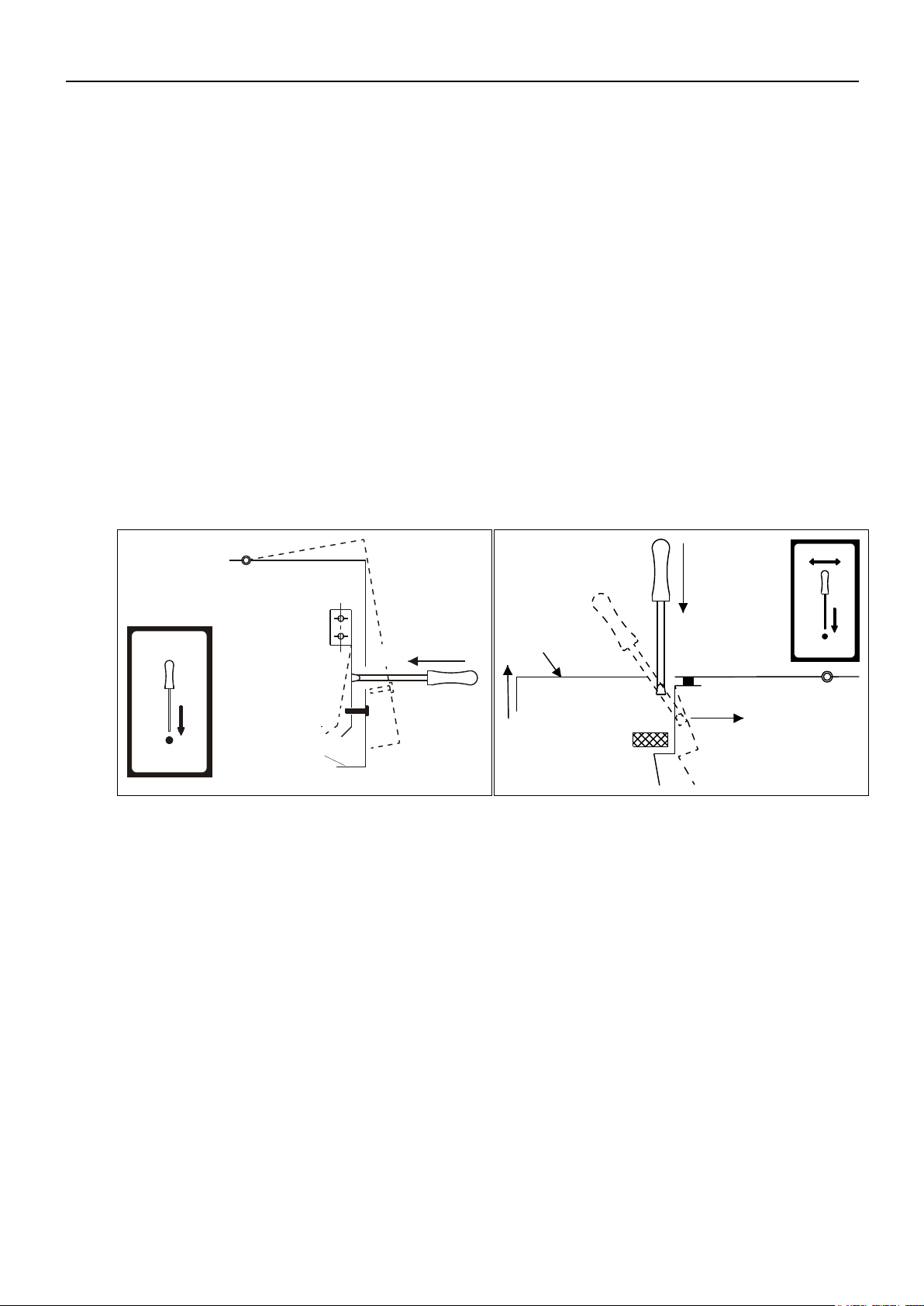
BYPASS VALVE
Fig. 2-1 We distinguish between two types of tractor hydraulic systems: “open centre
hydraulic” (also called “fixed pump”) and “closed centre hydraulic” (also called
“variable pump”).
If the tractor is of the “open centre” type, the bypass valve must be open in order to
allow passage of oil back to the tractor and should only be activated when a function
on the machine is activated. If the valve is not open, this can be changed at the
thumbscrew.
If the tractor is of the “closed centre” type, the bypass valve must be closed in
order to allow the tractor to close the oil flow automatically when no functions are
active. If the valve is not closed, this can be changed at the thumbscrew.
The bypass valve is placed at the bottom of the valve block.
None of the hydraulic functions use more than about 15 litres of oil per minute.
Therefore the oil flow from the tractor should be set to 15 litres of oil per minute, if
possible. The bypass valve is preset to maximum 40 l/min. If this limit is exceeded,
there will be a loss of pressure which may heat the oil and the valves.
Page 24

2. CONNECTION TO TRACTOR
PIGB-186X-05 FCT1360 0218
- 24 -
Fig. 2-2
CONNECTION OF ELECTRIC SYSTEM
Fig. 2-2 The machine is equipped with full electronic operation of all the machine’s hydraulic
functions. The electronic operation consists of 2 units:
A control unit mounted on the machine together with the hydraulic system.
This unit activates the hydraulic valves.
A control box for operation of the hydraulic functions. This can be placed on
the right arm rest in the tractor cabin, allowing the driver easy access to it
while driving in the field, see figure 2-2.
The control box is equipped with detachable fittings which can be fastened in the
tractor cabin with screws, and it can subsequently be dismounted without tools.
The plug for the power supply is connected to a socket in the tractor cabin. This
should supply 12 V and allow minimum 15 A. If the tractor does not have the same
plug you should contact your dealer and get an adaptor.
IMPORTANT: When the machine is parked the control box should be placed in the
chute support on the drawbar.
Page 25
2. CONNECTION TO TRACTOR
PIGB-186X-05 FCT1360 0218
- 25 -
Fig. 2-3
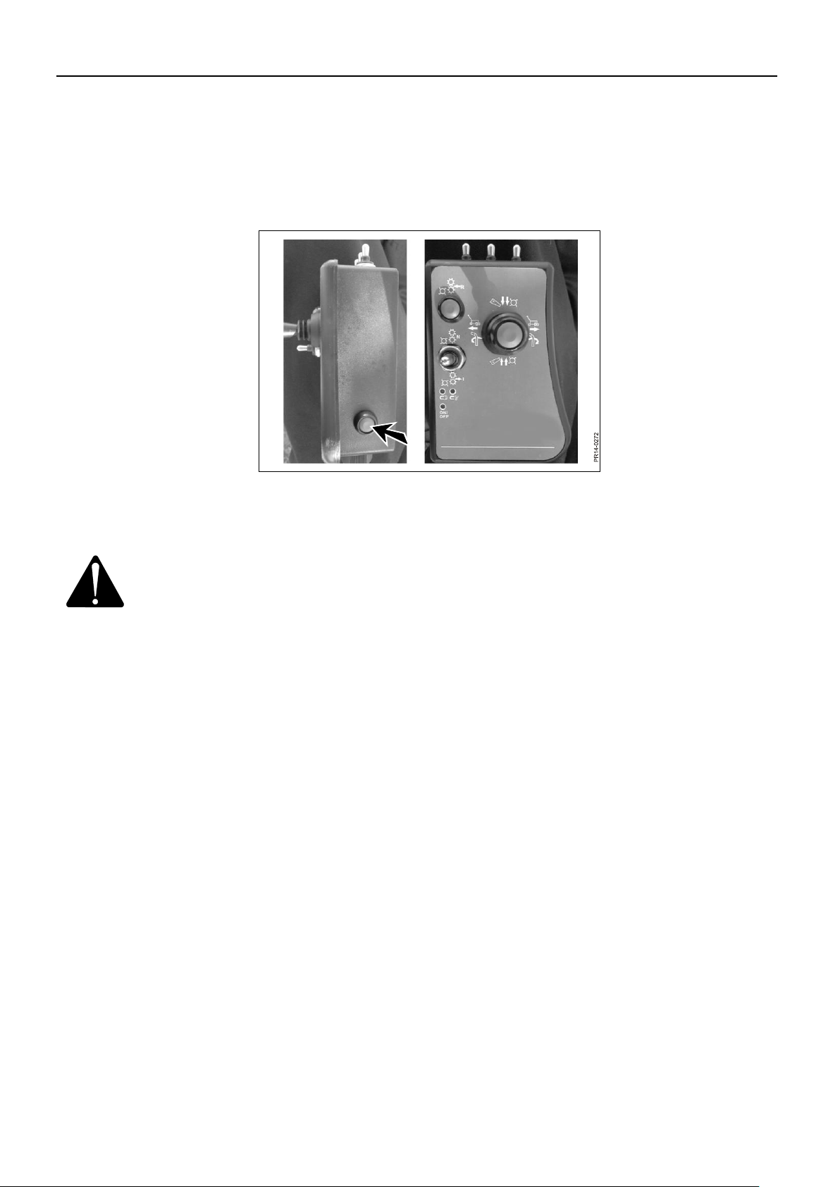
ELECTRO-HYDRAULIC CONTROL
The machine is operated from the control box which controls the electro-hydraulic
functions.
Fig. 2-3 The control is turned on and off on the side of the control box.
IMPORTANT: Remember to turn off the control box if the tractor is stopped for
some time. Although the machine is not in operation, several electric
coils may be activated. These will drain the tractor’s battery.
Page 26

PIGB-186X-05 FCT1360 0218
- 26 -
Fig. 2-5
Fig. 2-4
FUNCTIONS
Fig. 2-4 On the joystick:
Chute: Push to the left: The chute turns anti-clockwise. Push to the right: The chute
turns clockwise.
Drawbar: While pushing the button: Push to the left: The machine moves behind the
tractor. Push to the right: The machine moves out to the swath.
2. CONNECTION TO TRACTOR
Fig. 2-5 On the joystick:
Chute: Push forward: The deflector points downward. Push to the rear: The deflector
points upward.
Pick-up: While pushing the button: Push forward: The pick-up is lowered. Push to
the rear: The pick-up is raised.
It takes about 2 seconds to lower the pick-up completely so that the support wheels
can follow the ground.
Page 27
2. CONNECTION TO TRACTOR
PIGB-186X-05 FCT1360 0218
- 27 -
Fig. 2-6
Fig. 2-7
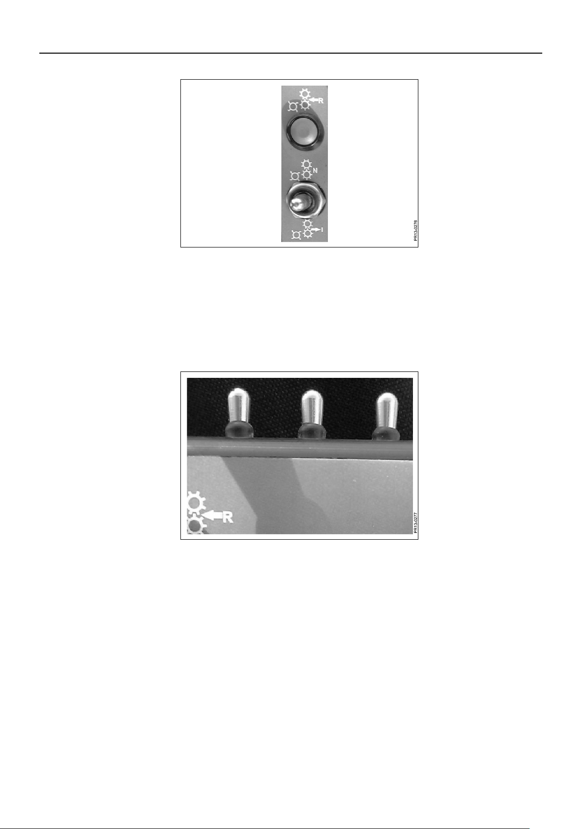
Fig. 2-6 Reverse function. Applies to feed rollers and pick-up.
Feed in: Move the toggle switch to the rear.
Neutral: Move the toggle switch forward for about 2 seconds and then back to the
middle position. Feed rollers and pick-up stay in neutral position.
Reverse: With the toggle switch in the middle position you reverse by holding down
the push-button. Reversing will stop when letting go of the button.
Fig. 2-7 There are 3 toggle switches at the front of the control box. One of them is used for
folding of the chute; the other two are intended for optional equipment. The toggle
switches automatically return to the neutral middle position after being activated.
Page 28

2. CONNECTION TO TRACTOR
PIGB-186X-05 FCT1360 0218
- 28 -
Fig. 2-8
Fig. 2-9
Control light
Fig. 2-8 This light is on when the control unit is switched on.
Fig. 2-9 Not used.
Page 29
PIGB-186X-05 FCT1360 0218
- 29 -
Fig. 2-10
PR11-5017
DRAWBAR AND PTO DRIVE SHAFT
The hitch eye of the drawbar is intended for a 30 mm hitch pin. The hitch pin must be
secured.
The drawbar load is 660kg.
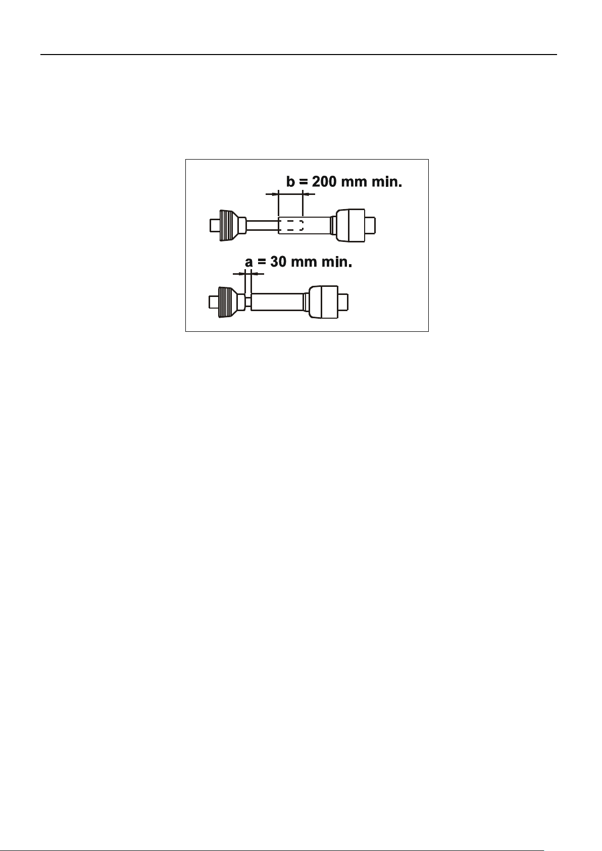
2. CONNECTION TO TRACTOR
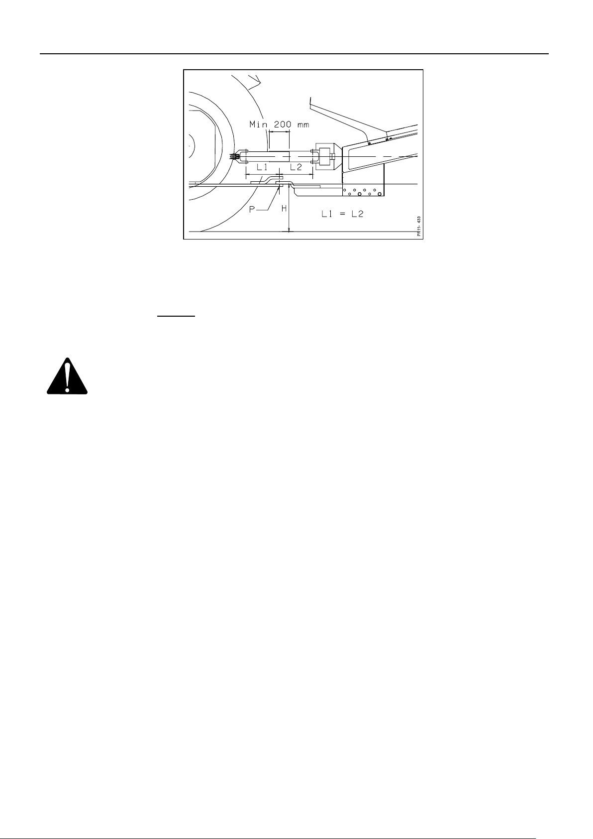
Fig. 2-10 Adjust the length of the PTO shaft so that it:
- in working position has minimum 200 mm overlap, see measure b.
- is not compressed more than the prescribed 30 mm in order not to bottom the shaft,
see measure a.
Adjustment of the length can take place by pulling out or pushing in the drawbar of
the tractor.
Page 30
2. CONNECTION TO TRACTOR
PIGB-186X-05 FCT1360 0218
- 30 -
Fig. 2-11
Fig. 2-11 The height H of the hitch eye must be adjusted so that the PTO shaft is horizontal.
The height can be changed by moving or turning the drawbar bracket.
To ensure longest possible life of the PTO shaft the following applies to standard
PTO shaft without wide angle: The length L1 must be equal to the length L2, i.e. the
centre of rotation P for the drawbar must be as close as possible under the centre
between the joints. The drawbar bracket on the chopper can be moved back and
forth in steps of 25 mm.
IMPORTANT: The drawbar must always be mounted and fastened with 2 bolts.
Page 31

2. CONNECTION TO TRACTOR
PIGB-186X-05 FCT1360 0218
- 31 -
Fig. 2-12
SHORTENING OF THE PTO DRIVE SHAFT
It is necessary to be very careful when shortening the PTO drive shaft. If the PTO
drive shaft is shortened too much, there is a risk that the profile tubes are drawn
apart which may cause serious damage.
Especially on hilly ground when the machine and the tractor have variable angles in
relation to each other. On the other hand, if the PTO drive shaft is not shortened
enough there is a risk of squeezing during sharp turns, which may cause high
frictional forces in the PTO drive shaft, which again will damage the axle joints.
Fig. 2-12 Fasten the halves of the shaft to PTO and PIC (fig. 2.10), respectively, when these
are right opposite each other with the machine in working position. (The longest
distance on this machine). Hold the shaft ends parallel to each other and mark the
wanted shortening, minimum 200 mm overlapping. Shorten all 4 tubes equally.
The ends of the profile tubes must be rounded off and burrs must be removed
carefully. It is very important that the tubes are smooth and clean before greasing.
Grease the tubes carefully before reassembling.
WARNING: Never turn so sharply that there are less than the prescribed 30
mm distance in order not to bottom the shaft. See measurement
a in fig. 2-10.
If the PTO drive shaft bottoms when turning sharply, there is a
risk that the shaft and/or other transmission parts are damaged.
FRICTION CLUTCH
On the PTO drive shaft between the drawbar and the gearbox there is a friction
clutch which ensures that the machine is not overloaded during operation.
Before starting a new machine, the clutch must be "aired". See section concerning
the friction clutch in chapter 7 "MAINTENANCE".
Page 32
PIGB-186X-05 FCT1360 0218
- 32 -
Fig. 3-2
Fig. 3-1
P
R
1
2
-
0
2
0
8
A
3. MOUNTING OF EQUIPMENT
Mounting should take place in a workshop on even ground. The basic machine must
always be mounted correctly to the tractor according to section 2 "CONNECTION TO
TRACTOR" before equipment and accessories are mounted.
HITCH FOR TRAILER
The machine can be supplied with combi-hitch or hydraulic hitch for connection of
trailer. The maximum drawbar load is 2000 kg. Maximum total weight of trailed
wagon: 15000kg.
COMBI-HITCH
3. MOUNTING OF EQUIPMENT
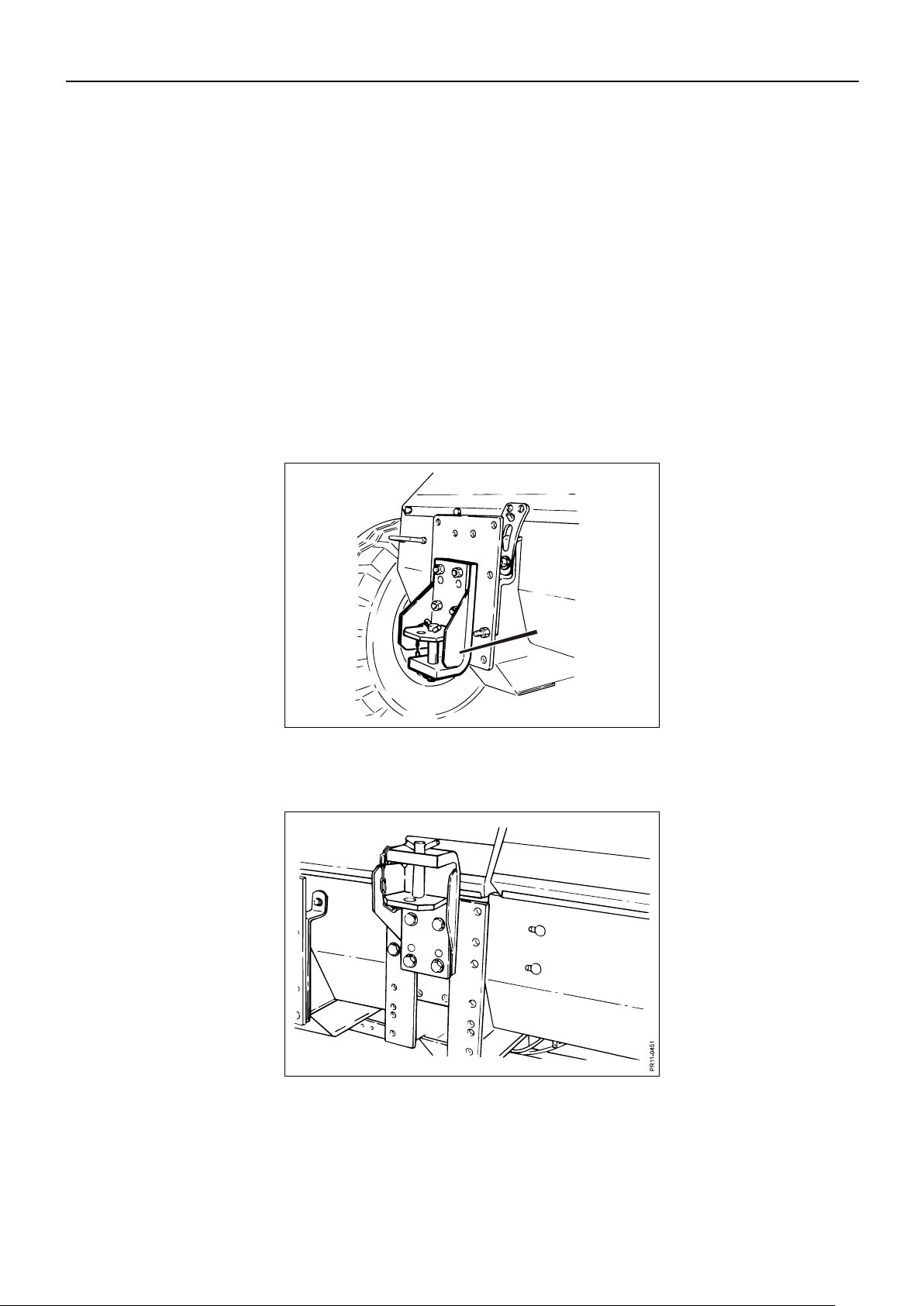
Fig. 3-1 Combi-hitch A mounted in lowest position.
Fig. 3-2 Combi-hitch mounted in uppermost position. This position is used for trailers with
overrun brake, e.g. in Germany.
Page 33
3. MOUNTING OF EQUIPMENT
PIGB-186X-05 FCT1360 0218
- 33 -
Fig. 3-3
PR12-1747
A
B
C
D
E
HYDRAULIC HITCH HOOK (AUTO-HITCH)
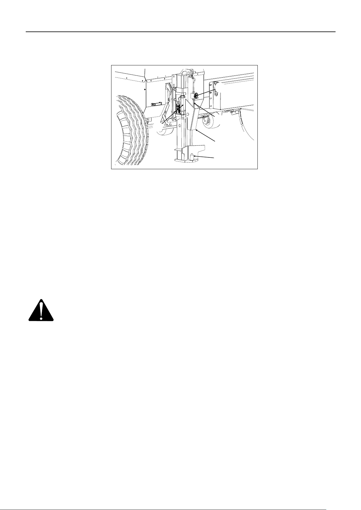
Fig. 3-3 The hydraulic hitch B is equipped with a hitch hook A which is raised and lowered
hydraulically by a double-acting cylinder C. The hoses from the cylinder C are
connected to a free valve on the valve block. Now the hydraulic hitch B can be
operated with one of the 3 toggle switches at the front of the control box.
Fig. 3-3 For connection of the trailer the machine must be reversed to the drawbar of the
trailer. The hitch hook A must be lowered and the hitch eye of the trailer is caught by
the hitch hook. Lift the trailer with the hydraulic cylinder C until it reaches its bottom
position. A hydraulic locking valve E which is mounted on the cylinder C ensures that
the hitch hook A stays in the raised position. If the trailer is equipped with plugs for
lighting and hoses for tipping and brakes these should be mounted subsequently.
IMPORTANT: When driving on public road with a trailer connected to the
hydraulic hitch B, the locking pin D MUST be removed from its
holder and lead through the frame on the hydraulic hitch B so
that the hitch hook A is locked mechanically, see fig. 3-4. This
must be done in order to observe the current traffic rules.
Page 34
3. MOUNTING OF EQUIPMENT
PIGB-186X-05 FCT1360 0218
- 34 -
Fig. 3-5
PR12-0212
A
B
Fig. 3-4
P
R
1
2
-
1
7
4
8
A
B
C
D
E
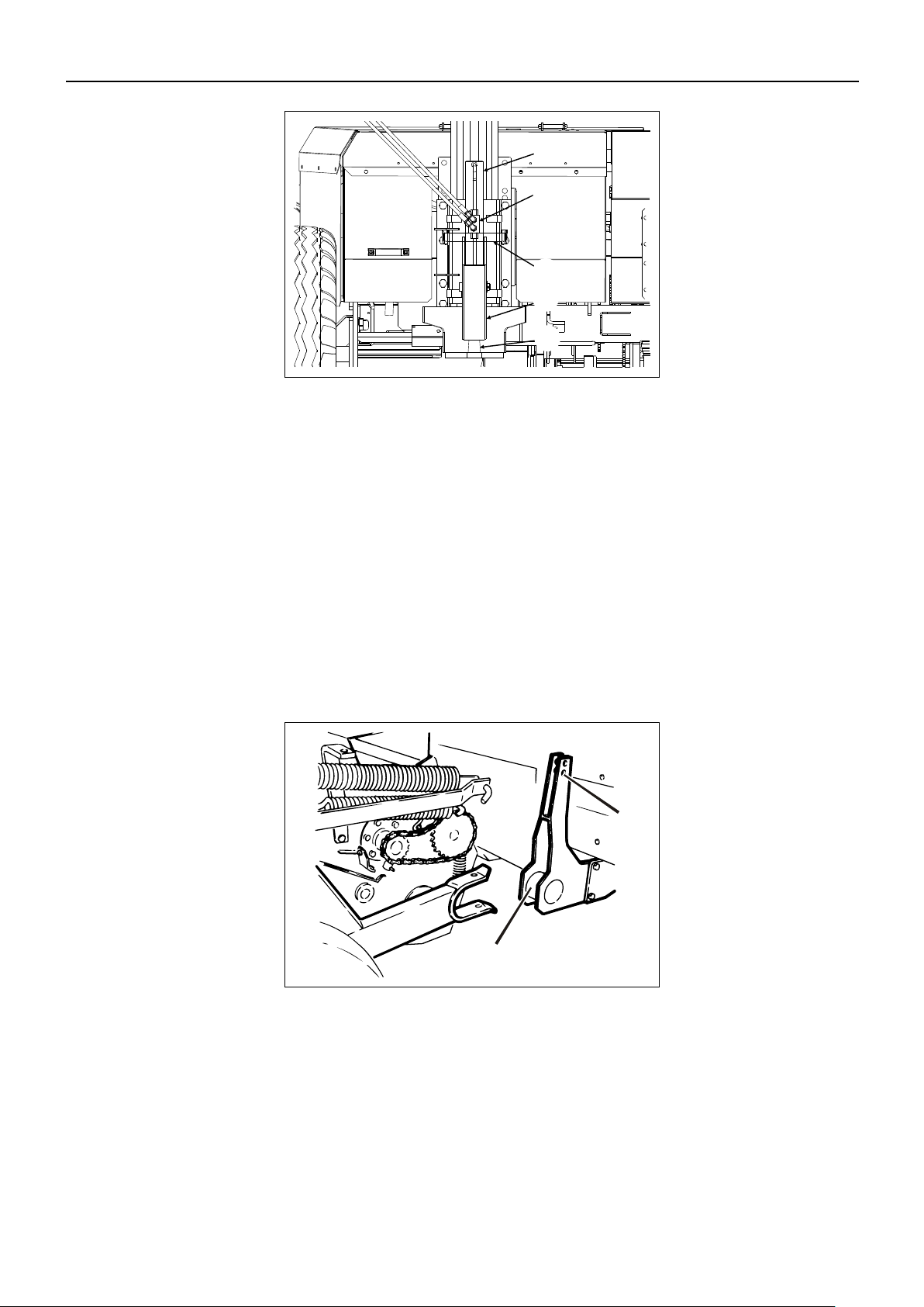
Fig. 3-4 The trailer is disconnected as follows: If the locking pin D is placed so that it locks the
hitch hook A, see figure 3-4, the locking pin D is removed and placed in the holder on
the hydraulic hitch B. Then the hitch hook A is lowered by activating the cylinder C.
When the hitch hook A has been lowered completely, the trailer is disconnected. Also
remember to disconnect plugs for lighting and hoses for tipping and brakes, if these
were mounted.
PICK-UP
Connection is preferably carried out on firm and even ground.
The basic machine is connected to the tractor according to section 2 “CONNECTION
TO TRACTOR”.
Fig. 3-5 Wheel the pick-up on the rollers to the machine so that the catch A is engaged.
Mount the 2 pins in order to fix the pick-up to the basic machine.
Attach the relief device to the pick-up at B.
Page 35
3. MOUNTING OF EQUIPMENT
PIGB-186X-05 FCT1360 0218
- 35 -
Fig. 3-7
Fig. 3-6
PR11-1402
A
Fig. 3-8
P
R
1
1
-
0
2
1
5
A
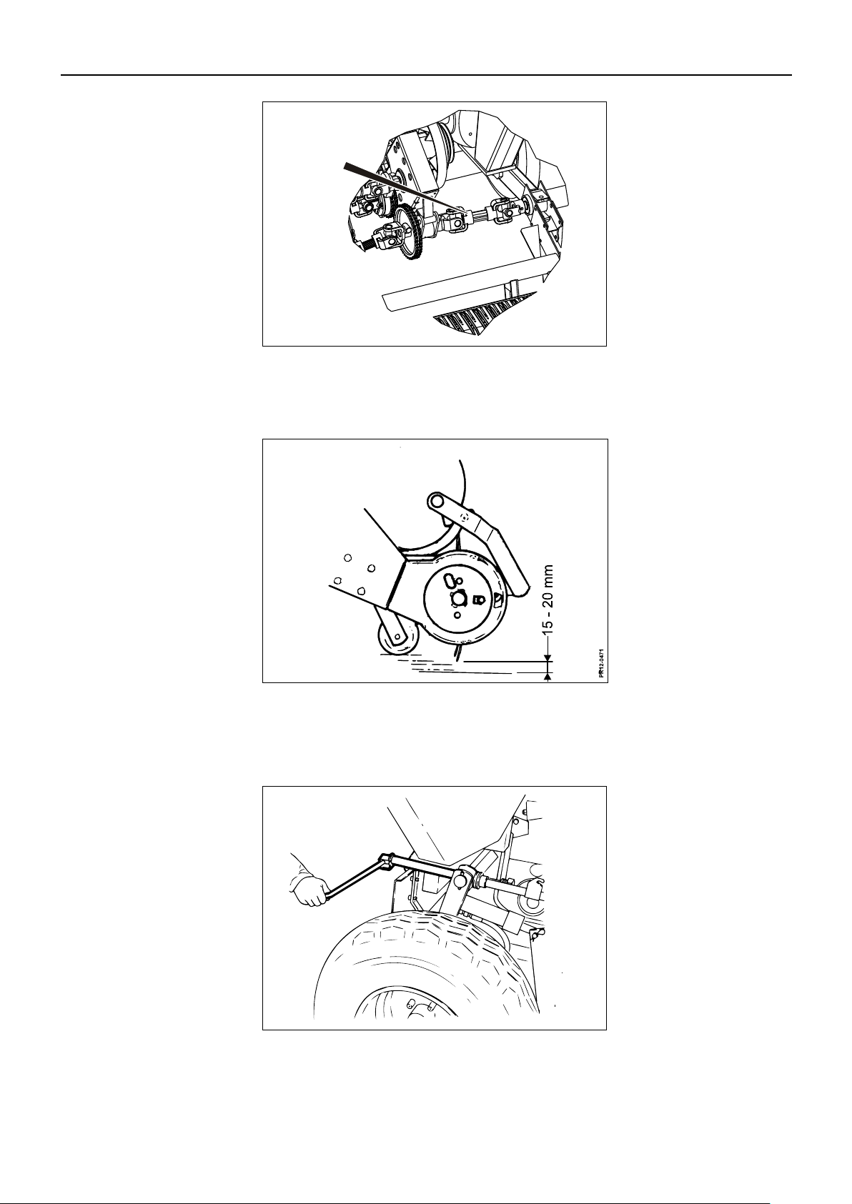
Fig. 3-6 Mount the PTO drive shaft A for the pick-up.
Fig. 3-7 The height of the rollers under the pick-up can be adjusted. Adjust the height so that
there is 15 – 20 mm distance between the point of the pick-up tines and the ground.
Fig. 3-8 Tighten the relief springs with the spindle A until the ground pressure for the pick-up
is maximum 30 kg.
Page 36

3. MOUNTING OF EQUIPMENT
PIGB-186X-05 FCT1360 0218
- 36 -
Fig. 3-9
PR12-1749
B
A
Fig. 3-10
PR12-1752
Fig. 3-9 Adjust the stop, B, for lift of the pick-up so that you obtain maximum lifting height but
also avoid that the pick-up collides with the drawbar at A.
Fig. 3-10 Connect the hydraulic hose for lift of auger and front roller to the quick-release
coupling at the left-hand catch.
Page 37

3. MOUNTING OF EQUIPMENT
PIGB-186X-05 FCT1360 0218
- 37 -
Fig. 3-11
PR12-0449a
B
A
TRANSPORT CONVERSION
Fig. 3-11 The drawbar is converted electro-hydraulically with the joystick on the control box.
The hydraulic cylinder A is equipped with a safety valve B which ensures that the
machine does not make any unintentional movements in case of leaking hoses.
Page 38

3. MOUNTING OF EQUIPMENT
PIGB-186X-05 FCT1360 0218
- 38 -
PR11-1855
Pos. 1
Pos. 2
Pos. 3
Fig. 3-12
FITTING CHUTES
There are 3 different chute options and 3 different positions of the bracket for chute
turning, in order to accommodate most needs.
NB! Not all machines offer the option for 3 positions of the bracket for chute turning.
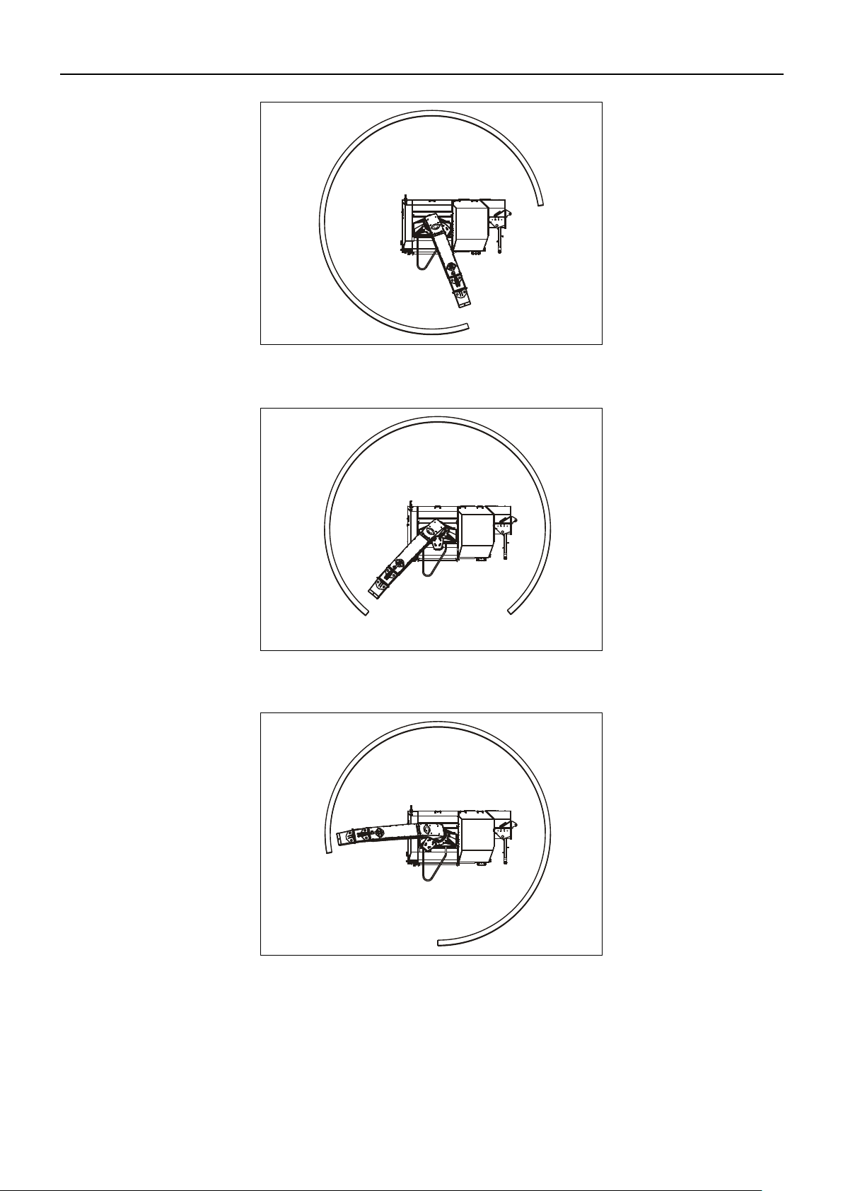
CHUTE TURNING
There are the following 3 positions for fitting the chute turning bracket, in order to
optimise unloading to a selected side.
Fig. 3-12 Pos. 1 for unloading to the right
Pos. 2 for unloading both sides. Cannot be used with the collapsible chute.
Pos. 3 for unloading to the left
When the chute is fitted, you must turn carefully from outer position to outer position
in order to ensure that the hydraulic hoses are fitted correctly and are long enough.
Page 39
PIGB-186X-05 FCT1360 0218
- 39 -
Fig. 3-13
PR11-1849
Fig. 3-14
PR11-1850
Fig. 3-15
PR11-1851
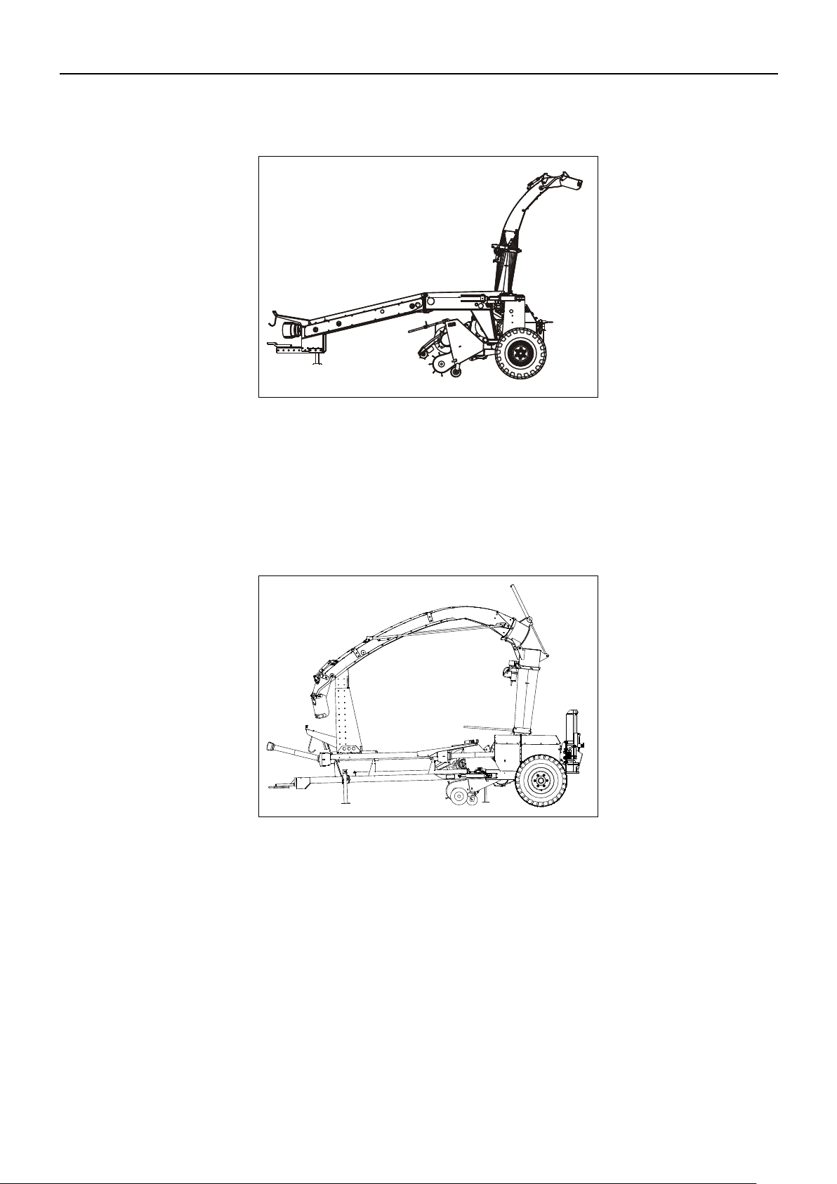
Fig. 3-13 Position 1
3. MOUNTING OF EQUIPMENT
Fig. 3-14 Position 2
Fig. 3-15 Position 3
NB! Not all machines offer the option for 3 positions of the bracket for
chute turning. Only position 3 is offered for these machines.
Page 40
3. MOUNTING OF EQUIPMENT
PIGB-186X-05 FCT1360 0218
- 40 -
Fig. 3-17
P
R
1
1
-
1
7
5
0
Fig. 3-16
PR11-1854
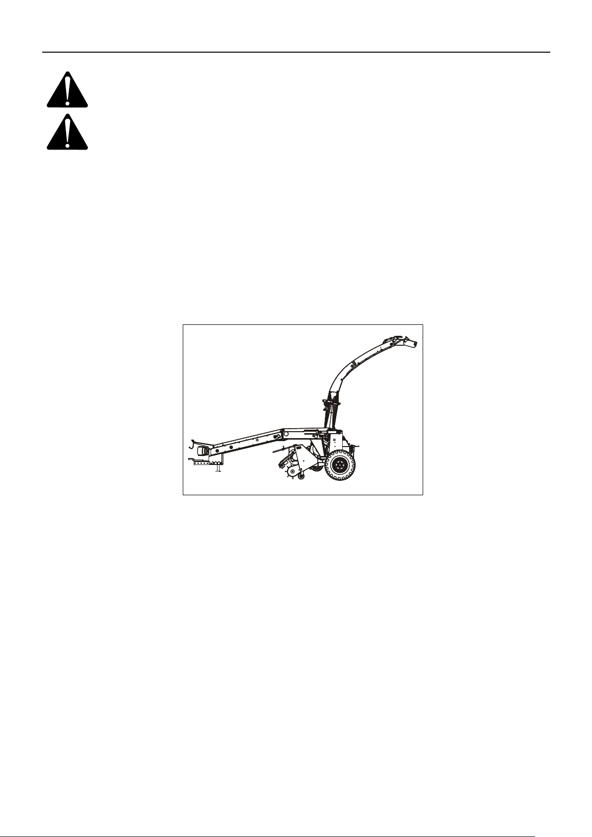
STANDARD CHUTE
Fig. 3-16 This is the standard chute that is supplied with the machine. It is approx. 3.8 metres
high in the transport position.
FOLDABLE CHUTE
Fig. 3-17 The machine can be fitted with a chute that permits loading of very high trailers. This
chute is over 4 m high. Therefore, and also because the chute/delivery chute will
otherwise be overloaded, it must be folded down during transport so that it rests on a
"chair" on the drawbar.
The chute is folded by a hydraulic cylinder which is operated by one of the toggle
switches at the front of the control box.
The chute is operated electro-hydraulically with the joystick and toggle switch on the
control box. Move the drawbar into transport position, turn the chute into a position
above the chair and fold it down until it rests on the chair.
Page 41
3. MOUNTING OF EQUIPMENT
PIGB-186X-05 FCT1360 0218
- 41 -
Fig. 3-18
PR11-1853
DANGER: The chute is over 4 m high. Be aware of high-voltage lines and keep
a safe distance to these.
WARNING: When you operate the chute make sure that persons keep a safe
distance from the machine. The hydraulic functions must be operated
from the tractor seat.
IMPORTANT: Be careful not to hit the tractor cabin.
IMPORTANT: Do not move the drawbar while the chute is resting on the chair.
IMPORTANT: Do not turn the chute while it is resting on the chair.
IMPORTANT: The chute must always rest on the chair during transport. This is due
to the Road Traffic Act and also because the chute/delivery chute
may get damaged, for instance if you drive fast on uneven ground.
CHUTE FOR PARALLEL OPERATION
Fig. 3-18 The machine can be fitted with a chute that has a transport height of 4.4 metres. This
chute cannot be folded for transport.
Page 42

3. MOUNTING OF EQUIPMENT
PIGB-186X-05 FCT1360 0218
- 42 -
Fig. 3-19
PR11-1852
A
B
Fig. 3-19 When this equipment is fitted, it is important that an extra spring A is fitted for chute
relief, in order to compensate for the added weight of the chute. Bracket B must be
moved to the indicated position so that the wire is not too short.
Page 43
3. MOUNTING OF EQUIPMENT
PIGB-186X-05 FCT1360 0218
- 43 -
Fig. 3-20
P
R
1
1
-
0
4
5
0
A
Fig. 3-21
P
R
1
2
-
0
4
5
6
A
LIGHTING KIT
The machine can be equipped with universal lighting kit consisting of two light units
with tail light and flasher, fittings for assembling plugs and cables and wiring system
with plugs to the tractor. The equipment is easy to retro-fit on your machine.
Fig. 3-20 In the left-hand side the light A is mounted on the main frame right beside the left
wheel.
Fig. 3-21 In the right-hand side the light A is mounted on rear lower guard right beside the right
wheel.
Page 44

3. MOUNTING OF EQUIPMENT
PIGB-186X-05 FCT1360 0218
- 44 -
Fig. 3-22
P
R
1
2
-
0
4
4
9
C
Fig. 3-22 The fitting C with plugs for the 2 light units is placed rearmost at the top of the
bracket for the drawbar.
The cable with the plug for the tractor is placed along the drawbar together with the
hydraulic hoses.
Page 45

PIGB-186X-05 FCT1360 0218
- 45 -
PR12-1751
A
Fig. 4-2
Fig. 4-1
PICK-UP
4. ADJUSTMENTS
4. ADJUSTMENTS
Fig. 4-1 The pick-up is equipped with support rollers made of steel which are adjustable in
height. You should keep the pick-up at such a height that the tines do not hit the
ground and leave earth in the crop and can also pick up the grass without waste.
KONGSKILDE recommends a distance between the pick-up tines and the ground of
15 to 20 mm.
Fig. 4-2 The distance A between the pick-up roller and the crossbar is adjusted so that they
are as close as possible without colliding.
Page 46

4. ADJUSTMENTS
PIGB-186X-05 FCT1360 0218
- 46 -
Fig. 4-3
The auger on the pick-up is equipped with a slip clutch. The slip clutch of the auger is
adjusted so that it releases before the other friction clutches in the machine.
The highest capacity is obtained by working at a forward speed where you drive
without blockage in the auger. If there is a blockage around the auger you stop and
force the crop out of the machine by using the reverse function. See also chapter 6
"WORKING IN THE FIELD".
A continuous and even flow through pick-up and auger is the best way to avoid
blockages inside the machine, and thus avoid long operational stoppages.
The operator should always ensure spare friction discs for the slip clutch on the
auger are in the tool box. If this clutch has often been in operation, the coating of the
friction discs is worn and it cannot transfer sufficient transmission. It may therefore be
necessary to replace the friction discs, but remember they have to be of the same
number and quality.
OPENING OF ROTOR HOUSING
Fig. 4-3 The chute must be lowered in order to open the rotor housing. In order to make this
easier, the chute is relieved by strong springs.
DANGER: First ensure that no other persons than the operator are in the
vicinity.
WARNING: The hydraulically collapsible chute (accessory) is so heavy that
the rotor housing cannot be opened manually for access to the
chopping rotor. Instead, please use the procedure described in Fig.
4-9 – Fig. 4-13.
WARNING: The chute for parallel operation (accessory) requires two people to
open and close the rotor housing, as the weight of this exceeds the
permitted amount.
Page 47

4. ADJUSTMENTS
PIGB-186X-05 FCT1360 0218
- 47 -
PR11-1766
Fig. 4-4
Fig. 4-6
Fig. 4-5
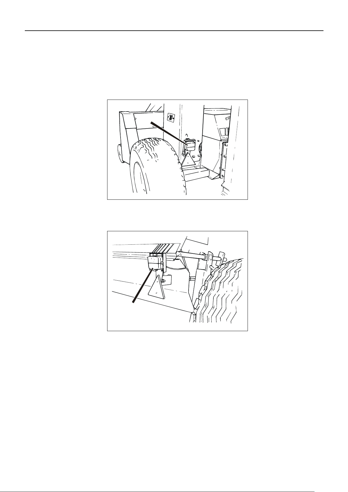
Fig. 4-4 1) Turn the chute to the rear. Turn the deflectors to the middle of the working area.
Fig. 4-5 2) Open the cover of the rotor housing and the left cover.
Fig. 4-6 3) Open the clips on the front of the rotor housing.
Page 48
4. ADJUSTMENTS
PIGB-186X-05 FCT1360 0218
- 48 -
PR13-0284
Fig. 4-7
Fig. 4-8
Fig. 4-7 4) Using the handle, turn the chute backwards and down, which will open the rotor
housing.
5) The rotor housing is closed in the same way, although in the reverse order.
Fig. 4-8 When the rotor housing is closed, it is a good idea to lift the chute the first part of the
way.
Page 49

4. ADJUSTMENTS
PIGB-186X-05 FCT1360 0218
- 49 -
PR12-1753
A
Fig. 4-9
P
R
1
2
-
1
7
5
4
B
B
Fig. 4-10
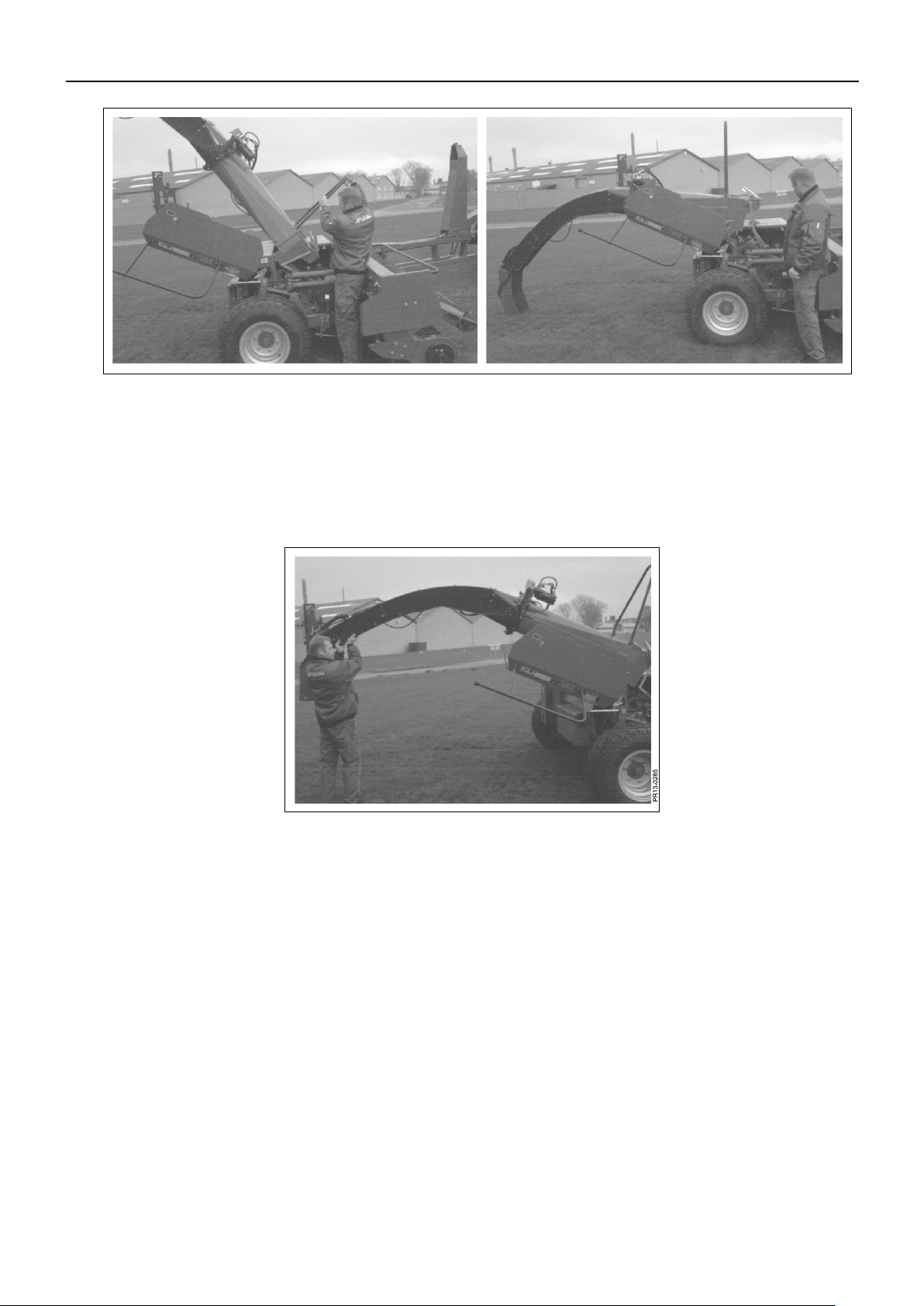
COLLAPSIBLE CHUTE
WARNING: The chute is so heavy that the rotor housing cannot be opened
manually when you want to get access to the chopping rotor. Use
this procedure instead:
DANGER: First, make sure that no persons are near. The hydraulic functions
must be operated from the tractor seat.
Fig. 4-9 Turn the chute to the rear. Adjust the deflectors A to the middle of the working area.
Fig. 4-10 Fold down the chute to about 1.5 m above the ground and mount the wheels B with
the pin and split pins.
Page 50
4. ADJUSTMENTS
PIGB-186X-05 FCT1360 0218
- 50 -
PR12-1756
C
C
Fig. 4-12
P
R
1
1
-
1
7
5
5
Fig. 4-11
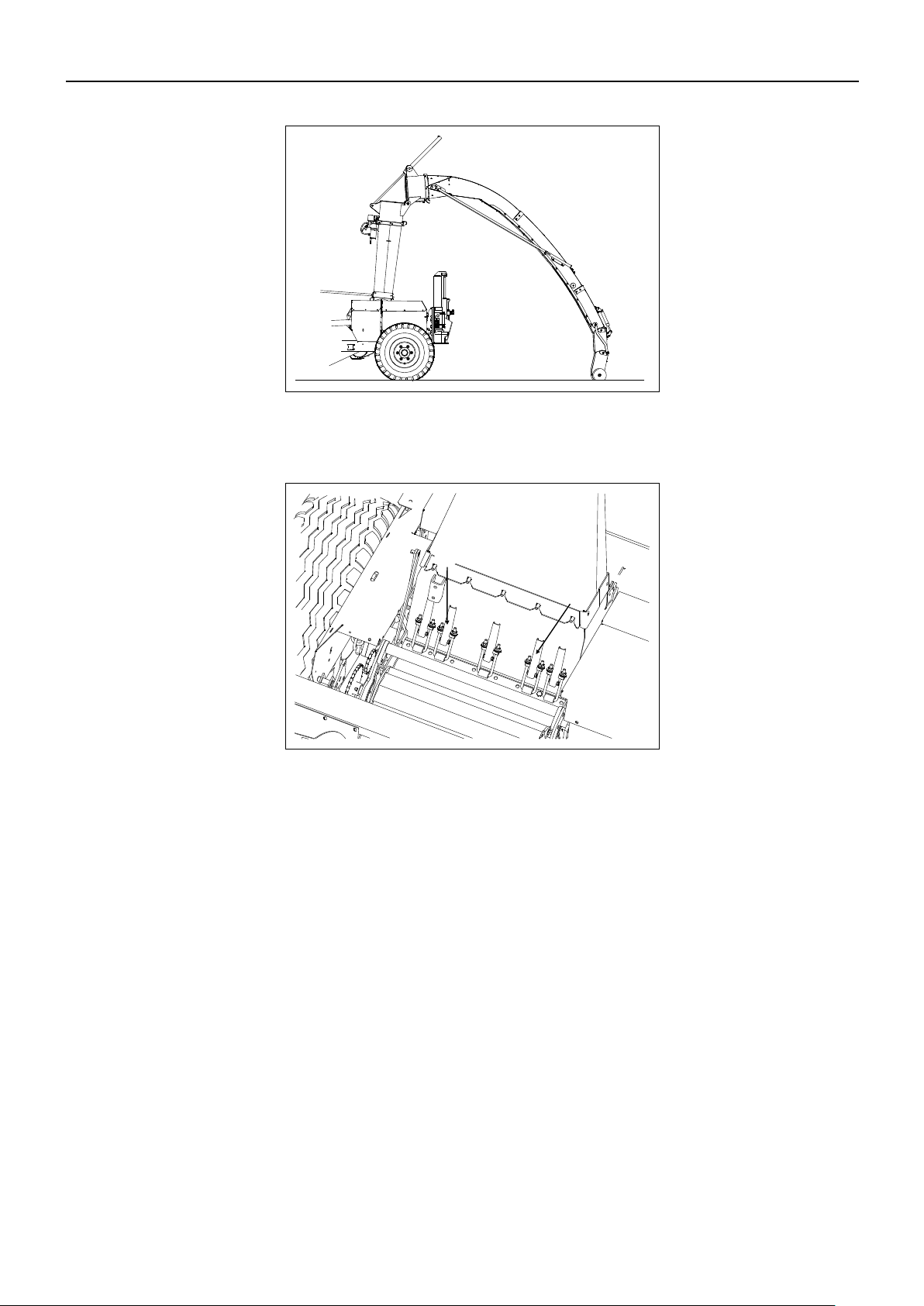
Fig. 4-11 Fold down the chute until the wheels rest on the ground.
Fig. 4-12 Now the lock clamps C at the front of the rotor housing can be opened safely.
Page 51

4. ADJUSTMENTS
PIGB-186X-05 FCT1360 0218
- 51 -
PR12-1757
Fig. 4-13
Fig. 4-13 Move the chute cylinder in direction “Chute closed”, whereby the rotor housing is
opened.
When closing the rotor housing, follow the same procedure in reverse order.
Page 52
4. ADJUSTMENTS
PIGB-186X-05 FCT1360 0218
- 52 -
Fig. 4-14
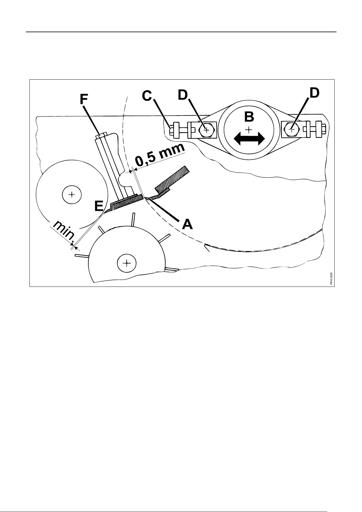
ROTOR AND ROLLER SECTION
Fig. 4-14 The distance A between the blades of the rotor and the shearbar must be checked
regularly with the delivered gauge (distance measuring device). You should aim at a
distance of 0.5 mm. If it is necessary to adjust the distance, loosen the 2 bearing
housings B and adjust with the screws C. When the distance has been checked, the
bolts D of the bearing housings are tightened with a torque wrench to 40 kgm (400
Nm).
The machine is equipped with a scraper for the smooth roller E. The scraper is
mounted together with the reversible shearbar just mentioned.
The scraper is placed as close to the smooth roller E as possible without touching it.
The distance between the scraper and the smooth roller should be maximum 0.5
mm. Tighten the bolts F with a torque wrench to 10-12 kgm (100-120 Nm). Wrong
adjustment of the scraper may result in overheating of the smooth roller and
operational stoppage.
Page 53

4. ADJUSTMENTS
PIGB-186X-05 FCT1360 0218
- 53 -
Fig. 4-15
PR12-0458
A
B
Fig. 4-16
P
R
1
1
-
0
2
3
1
M
a
x
.
3
m
m
G
Fig. 4-15 The scraper is dismounted by removing the screws F (on fig. 4-14), which also
secure the shearbar, after which scraper and shearbar can be pulled out of the
opening A in the rotor housing. The spring B for the serrated roller must be loosened
or dismounted to get enough space.
If the shearbar has been worn, it can be reversed for a new sharp edge.
Fig. 4-16 The distance between the smooth roller and the serrated roller should be maximum 3
mm. Adjustment is made with the bolts G at both sides of the rotor housing.
Page 54

4. ADJUSTMENTS
PIGB-186X-05 FCT1360 0218
- 54 -
Fig. 4-17
PR11-0332
M
i
n
.
0
,
5
m
m
Fig. 4-18
PR11-1404
A
Fig. 4-17 Under some conditions, crop substance (small particles) can accumulate in the
shaded area and get so compact that this may result in an overloading of the
transmission driving the rollers.
Check the area after every 8 hours of operation and remove possible crop residue.
Check, and if necessary adjust, the distance between scraper and smooth roller. The
checking frequency can be reduced when the operator knows the machine under all
conditions.
Fig. 4-18 The roller chain for feed intake and pick-up, front left-hand side, should be kept
sufficiently tight. Chain adjustment takes place by means of spacers A.
Page 55

4. ADJUSTMENTS
PIGB-186X-05 FCT1360 0218
- 55 -
Fig. 4-19
P
R
1
2
-
0
2
2
2
B
Fig. 4-19 Under the roller section a bottom plate B can be mounted as option. This plate can
be mounted when working in very dry and/or short crops to avoid waste under the
rollers.
IMPORTANT: When working under normal conditions we recommend you to
drive without this bottom plate as, otherwise, material can
accumulate under the rollers causing reduced capacity and
unnecessary overload of the transmission.
However, when driving in a crop where there is an excessive
waste under the rollers, the bottom plate should be mounted.
Waste material should be removed on a regular basis.
Page 56
4. ADJUSTMENTS
PIGB-186X-05 FCT1360 0218
- 56 -
Adjustment
Theoretical cutting length
1
15 mm
2
9 mm
Fig. 4-21
PR11-0217
Fig. 4-20
CUTTING LENGTHS
Fig. 4-20 The cutting length is changed by shifting between 2 placements of the V-belts driving
the gearbox for the feed rollers.
The figures in the table indicate the theoretical cutting length in mm.
Fig. 4-21 The cutting lengths can be doubled by removing every second row of blades in the
rotor.
Page 57

4. ADJUSTMENTS
PIGB-186X-05 FCT1360 0218
- 57 -
Fig. 4-22
P
R
1
1
-
0
2
3
2
M
i
n
.
1
2
m
m
REPLACEMENT AND ADJUSTMENT OF BLADES
When replacing a single blade the blade must be placed at the same distance to the
shearbar as the existing blades. To ensure that the rotor is in balance it may be
necessary also to replace the opposite blade as a used blade has a different weight
compared to a new blade.
Even if there is no visible damage to the blade bolts, they should always be replaced
together with the blades as they might have been overloaded.
CAUTION: Check the distance between the blade and the shearbar (0.5
mm) with the supplied gauge before the bolts are tightened.
WARNING: Only use original blade bolts when replacing. Tighten the blade
bolts with a torque wrench to 40 kgm or with the supplied
spanner using approx. 40 kg leverage.
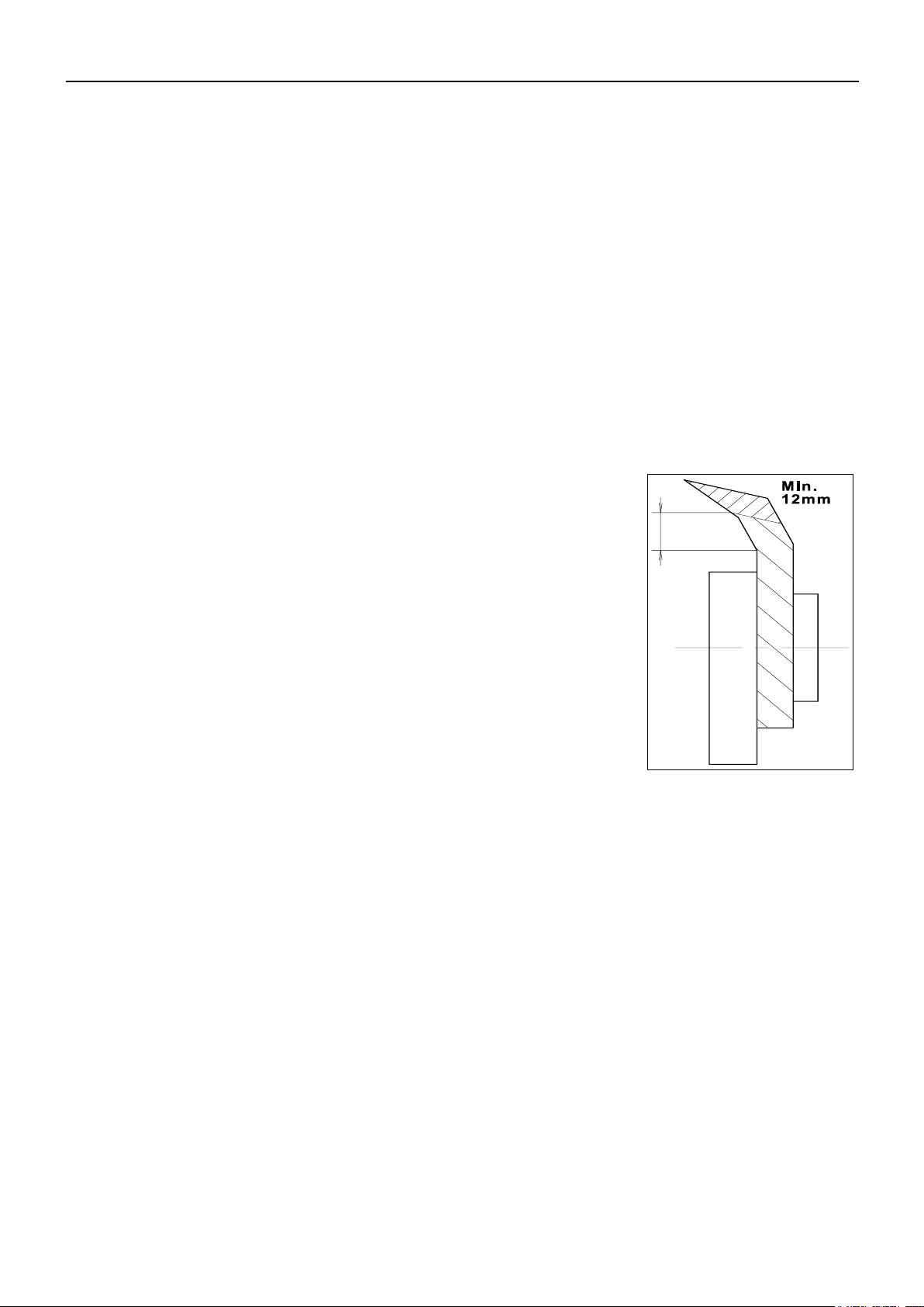
Fig. 4-22 When the blades have been worn max. 8 mm or to the first bend, i.e. approx. 12 mm
above the straight piece they must be replaced.
DANGER: When all blades on the rotor have been worn and the rotor
adjusted towards the shearbar, it MUST be adjusted back again
before new blades are mounted. Otherwise there is a risk that
the new blades collide with the shearbar when the rotor is
turned.
Page 58

4. ADJUSTMENTS
PIGB-186X-05 FCT1360 0218
- 58 -
Fig. 4-23
P
R
1
1
-
0
4
7
0
1
7
8
Ø
4
8
0
PR11-1881
A
Fig. 4-24
Fig. 4-23 When mounting new blades they must be pulled out so that the outer diameter on the
rotor is 480 mm (from rotor tube to blade point = 178mm).
Fig. 4-24 When replacing blade bolts, it is important to ensure that the area A under the bolt
heads is greased.
Page 59

4. ADJUSTMENTS
PIGB-186X-05 FCT1360 0218
- 59 -
GRINDING
Adjustment of the PTO drive shaft for the rotor to or from grinding position,
respectively, may only take place when the tractor and the machine have been
stopped and the rotor has come to a complete standstill. The rotor may only
rotate when the grinding device is in grinding position.
Check before grinding:
- that the grindstone is undamaged.
- that the device is easily sliding back and forth.
- that the device is parallel with the rotor.
The grinding device is correctly adjusted from the factory and therefore there is
normally no need for adjustment, but if it has been dismounted adjustment can be
made at the oblong holes of the lateral guides. The bolts must be tightened firmly
after the adjustment.
The stone is fed by turning the handle.
Normally you should grind the blades once a day – but avoid too much grinding
since it will reduce the life of the blades.
CAUTION: Protect your eyes – always use safety glasses when grinding.
The guard above the grinding device must be closed while
grinding.
Page 60

4. ADJUSTMENTS
PIGB-186X-05 FCT1360 0218
- 60 -
Fig. 4-25
P
R
1
1
-
0
2
1
8
Fig. 4-26
P
R
1
2
-
0
4
4
6
a
A
GRINDING OPERATION
1. Lift the guard above the grinding device.
Fig. 4-25 2. Lower the guard between the grinding device and the rotor so that there is free
space between the device and the rotor.
Fig. 4-26 3. Adjust the grindstone so that there is 2-3 mm clearance between the stone and
the blades by turning the handle A.
Page 61

4. ADJUSTMENTS
PIGB-186X-05 FCT1360 0218
- 61 -
Fig. 4-27
Fig. 4-28
Fig. 4-27 4. Mount the PTO drive shaft for the rotor on the free pin on the rotor housing.
Fig. 4-28 The PTO drive shaft must be fixed at pos. 2 whereby the gear wheels are
engaged and the rotor will rotate in the opposite direction.
5. Close all guards.
6. Start the tractor and keep the rpm at a little above idle speed.
Fig. 4-26 7. Feed carefully by turning the handle A until the stone touches the blades. Move
the stone in a sliding movement across the whole rotor and back again. Feed
some more and repeat the movement across the whole width of the rotor so
that the blades in the whole width of the rotor are sharpened.
8. Push the handle in after grinding. Stop the tractor and when the rotor has come
to a complete stop, the guard between the device and the rotor must be lifted
back into its right position. The PTO drive shaft for the rotor must be moved
back to the pin for normal direction of rotation of the rotor.
WARNING: REMEMBER, only grind with CLOSED guards.
For safety's sake check the distance between blades and shearbars again with the
gauge.
Check wear of the grindstone regularly. If the stone has been worn down to a
thickness of 10 mm it must be replaced.
Page 62
4. ADJUSTMENTS
PIGB-186X-05 FCT1360 0218
- 62 -
Fig. 4-29
P
R
1
1
-
0
2
3
7
Max. 5 mm
1
5
º
ROUGH GRINDING
Fig. 4-29 To avoid unnecessary power consumption and excessive wear of the grindstone
when working with the harvester, it is necessary to make a rough grinding or
adjustment of the blades when the cutting edge is 5 mm wide or more. Grind the rear
edge to an angle of approx. 15°.
Rough grinding can be made by means of an angle grinder with the rotor and blades
positioned in the machine.
CAUTION: Be careful not to grind down the cutting edge (front edge) of the
blades.
Block the rotor with a firm object (a piece of wood or the like)
during rough grinding to make sure that the rotor does not
move during this operation.
Page 63

4. ADJUSTMENTS
PIGB-186X-05 FCT1360 0218
- 63 -
Fig. 4-30
PR12-0439
B
C
REVERSE
The reverse function can be used at full rpm (1000 rpm on the PTO), but we
recommend you to reduce the rpm to relieve the machine as much as possible
and reduce the wear of the rubber disc.
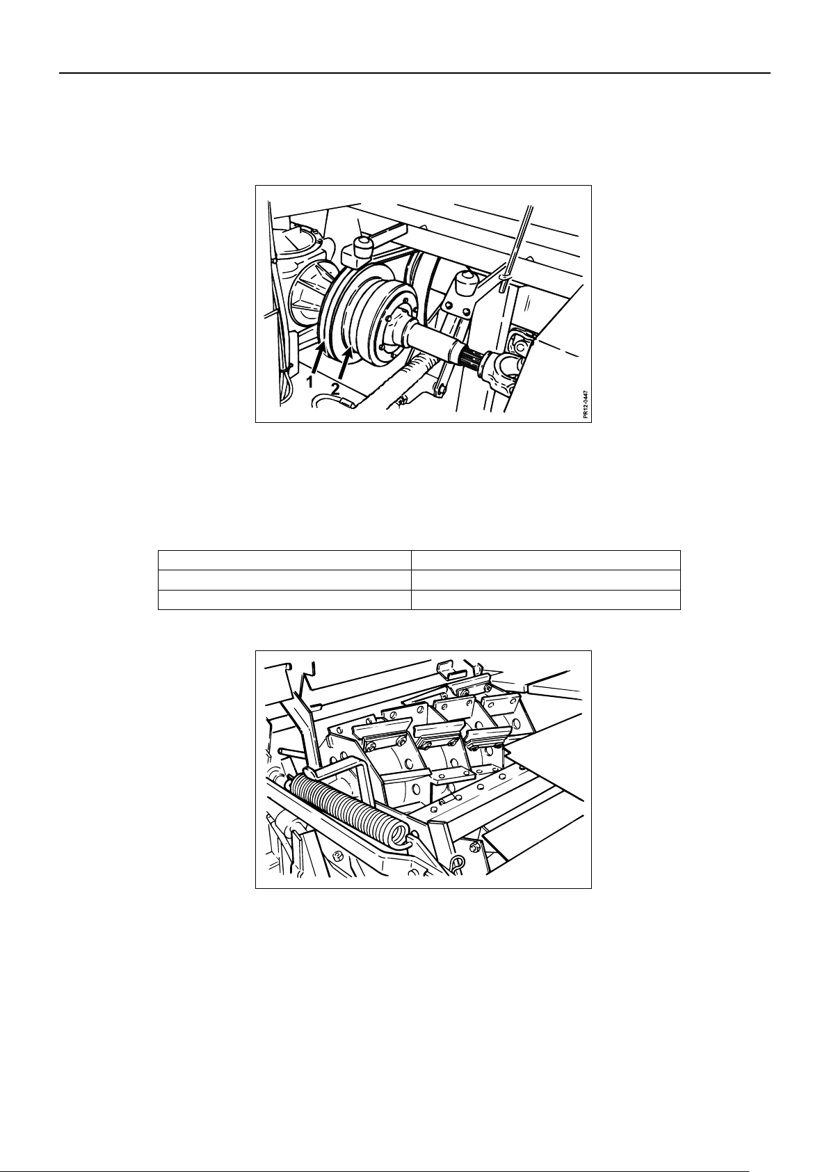
Fig. 4-30 During reverse, the overlap between the steel friction disc and the rubber disc is 5+/-
3mm. It is not necessary to make any adjustment in case of wear because the
cylinder always has the constant pressure which is determined by the pressure relief
valve.
CAUTION: Only use the reverse function shortly each time to ensure
correct functioning and long life of the rubber disc.
Page 64

4. ADJUSTMENTS
PIGB-186X-05 FCT1360 0218
- 64 -
Fig. 4-31
P
R
1
2
-
0
4
3
8
(430 mm)
450 mm
A B
Fig. 4-31 The tightening of the V-belt drive is also adjusted automatically. It is determined by
the pressure relief spring A. The tightening of the V-belt drive can be changed by
turning the nut B on the spindle in the pressure relief spring until the spring has the
correct length:
In case of long chopping length, 15 mm, the length must be 450
mm.
In case of short chopping length, 9 mm, the length must be 430
mm.
The lengths apply to reserve function in “feed in”.
WARNING: The tightening of the spring should NOT be increased, in
relation to the indicated lengths, as this may overload the
transmission. The V-belt drive works as a belt clutch and slips if
the feed intake is overloaded.
With this clutch function the attentive operator can change into
a lower gear when the belts slip and thereby avoid blockage in
the feed intake section.
Page 65

4. ADJUSTMENTS
PIGB-186X-05 FCT1360 0218
- 65 -
Fig. 4-32
PR12-0438a
0-1 mm
B
A
NEUTRAL POSITION
The neutral position is between the reverse function where the rubber disc and the
friction disc are in mesh and normal working position where the belt drive is tightened
by the spring and drives the feed intake.
In neutral position the belt drive for the feed intake section is slackened and it stands
still. This is not a position which should be considered as standstill of the
machine, for instance because the blade rotor still rotates. Moreover, an empty,
smooth-running feed intake can still be driven by the slight friction from the slackened
belts.
WARNING: Do not approach the machine when the feed intake is in neutral
position and the rotor is rotating. Neutral position does not
guarantee that the feed intake will not start.
Fig. 4-32 In neutral position, with a new rubber disc, the distance between the rubber disc and
the steel friction disc should be approx. 0-1 mm. Adjustment of neutral position takes
place by turning the piston rod at A. It is not necessary to adjust in case of wear of
the rubber disc.
After any dismounting of the cylinder it is important that the factory setting of the free
thread length at B is 32 mm. The cylinder is without pressure when the reserve is in
“feed in".
Page 66

5. WORKING IN THE FIELD
PIGB-186X-05 FCT1360 0218
- 66 -
5. WORKING IN THE FIELD
GENERAL CONDITIONS
Adjust the machine to the maximum cutting length acceptable for the crop in
question. This will reduce the stress in the feed intake section and the transmission
and increase the possibility of working with the machine continuously without
blockages. Be aware that if the cutting length adjustment is too short, it increases the
power consumption and also the wear of blades.
Always work with sharp blades and correctly adjusted shearbar.
Under difficult conditions we recommend you to bring spare friction discs for the slip
clutch on the auger since these are worn each time the clutch is activated. After
some time the power which can be transmitted it reduced so much that the capacity
of the machine is lowered and the friction discs must be replaced. When replacing
discs remember that they must be of the same number and quality so that the
wanted torque can be transmitted and to secure maximum life.
SWATHING BEFORE CHOPPING
If it is possible to influence the swathing made before chopping it is important to
emphasise that regular and even swaths are optimal for the subsequent chopping
and will spare the tractor driver a lot of trouble.
The machine is equipped with a wide pick-up and if you want to use the capacity of
the machine through double swathing, it is desirable to place 2 swaths beside each
other within the width of the pick-up instead of raking. Raked swaths are often
irregular and the crop tangled which may cause blockages in the auger and/or feed
intake section.
Therefore, double swaths are optimal for a regular flow of crop through the machine.
Page 67
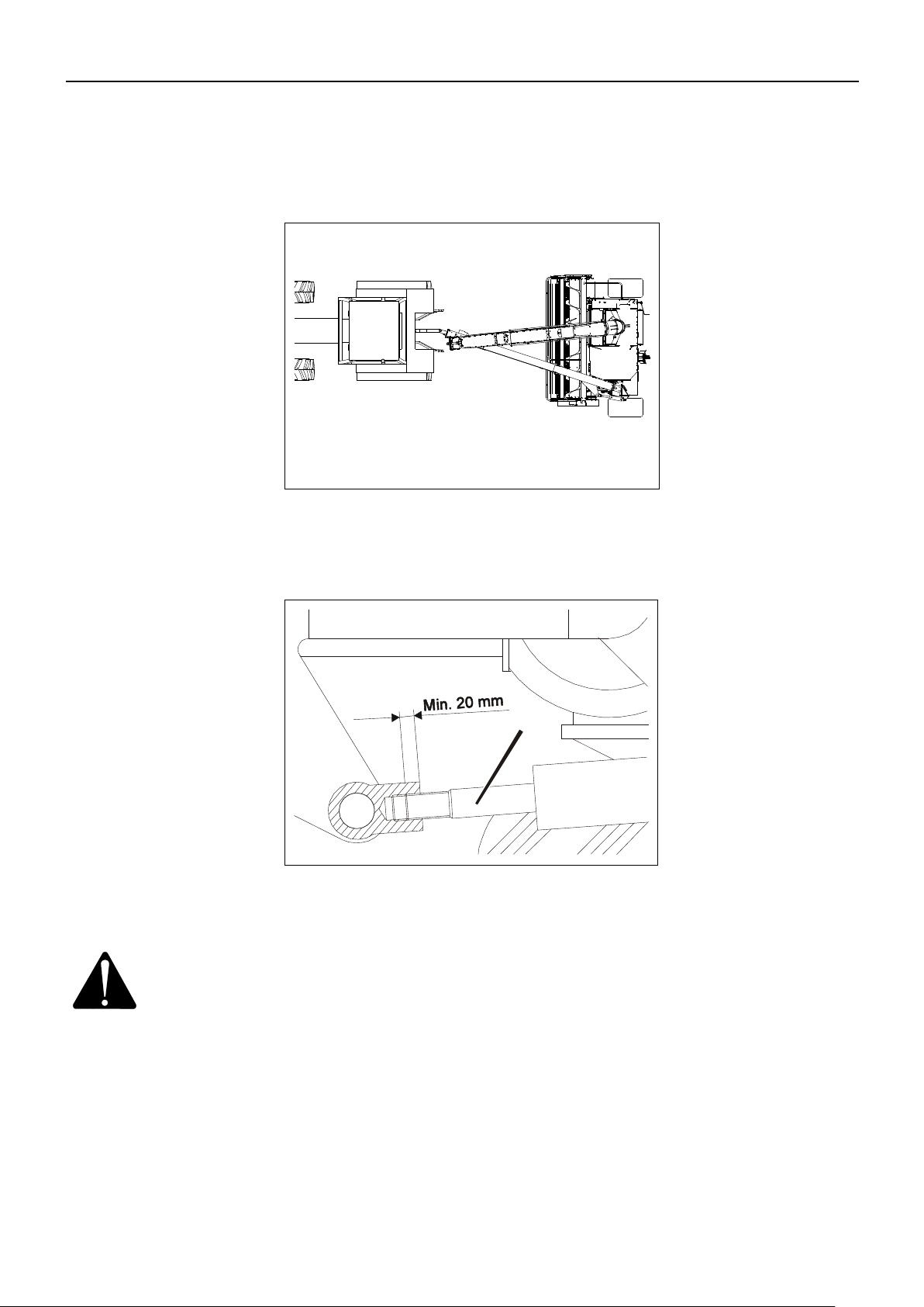
5. WORKING IN THE FIELD
PIGB-186X-05 FCT1360 0218
- 67 -
Fig. 5-1
PR11-1758
Fig. 5-2
P
R
1
2
-
0
4
3
4
A
TRANSPORT POSITION
Fig. 5-1 In transport position the machine must be placed straight behind the tractor. The
chute must be folded down to rest on the chair on the drawbar.
Fig. 5-2 The cylinder A for the drawbar can be adjusted in length in order to change the
position of the machine behind the tractor.
CAUTION: There must be minimum 20 mm thread in mesh between the piston
rod and the threaded piece.
Page 68
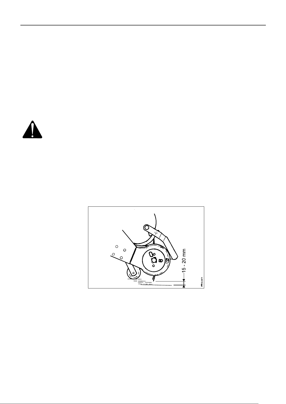
5. WORKING IN THE FIELD
PIGB-186X-05 FCT1360 0218
- 68 -
Fig. 5-3
STARTING IN THE FIELD
Gradually increase to the correct number of rpm. This is 1000 rpm on the PTO during
working, therefore start with approx. 1050-1100 rpm unloaded.
Drive slowly into the crop and increase the forward speed as long as the tractor can
keep the required number of revolutions of approx. 1000 rpm.
An inexperienced operator should always work with a capacity reserve in the
machine to avoid problems with the flow through the machine.
IMPORTANT: Always make sure that the tractor can keep the correct number of
revolutions of 1000 rpm on the PTO. This ensures a regular load of
the machine and you avoid torque increases (in case of reduced
rpm) which wears the safety clutches and the transmission.
To obtain optimal pick-up function it is important that:
The crop enters the machine regularly and that you, if possible, drive in the
opposite direction of the mower conditioner.
The forward speed is adjusted to the amount of crop and is not so high that
blockage is frequent.
You drive as straight as possible into the crop and are aware of this when
turning in the field.
Fig. 5-3 The pick-up is fitted with support rollers of steel which are adjustable in height. From
the factory the wheels have been adjusted so that there is 15-20 mm space between
the tines and an even and firm ground.
Check regularly that the pick-up tines do not reach further down than necessary to be
able to pick up the swath efficiently. If the tines hit the ground too hard they are
quickly worn and the drive of the pick-up may be overloaded.
Page 69

5. WORKING IN THE FIELD
PIGB-186X-05 FCT1360 0218
- 69 -
Fig. 5-4
P
R
1
2
-
1
7
5
9
C
Fig. 5-4 Before making any adjustment, the cylinder stop C must be engaged and secured
with pin.
Lift the pick-up completely during transport and when turning. When driving through
soft areas in the field, the pick-up can be lifted partly to avoid picking up earth etc.
The position of the pick-up is locked, both in the lifted and in the partly lifted position.
Only when the pick-up is completely lowered, can the support rollers follow the
ground. It takes about 2 seconds to lower the pick-up completely with the joystick
activated.
BLOCKAGE IN THE MACHINE
Auger and feed intake section:
In case of blockage in the auger or feed intake section, immediately move the feed
intake to neutral position and reduce the number of revolutions.
Hereby the auger and the feed intake stop immediately, and you can obtain an
overview of the situation.
DANGER: Do not approach the machine when the feed intake is in neutral
position and the rotor is rotating. Neutral position does NOT
guarantee that the feed intake will not start.
Now move the reverse system to reverse position at a low number of rpm (the pushbutton on the control box). Hereby the auger is lifted and the feed intake runs
“backwards” whereby the material in the machine is reversed out. We recommend
reversing slowly with the machine while the material is pushed out. This creates room
for the grass which is reversed out and leaves it as a regular “swath”.
After reversing, increase to normal number of rpm. Set the auger and feed intake
section to normal feed in (toggle switch on the control box). It is important to have a
normal number of rpm, otherwise the chute or the rotor might be clogged up.
Page 70
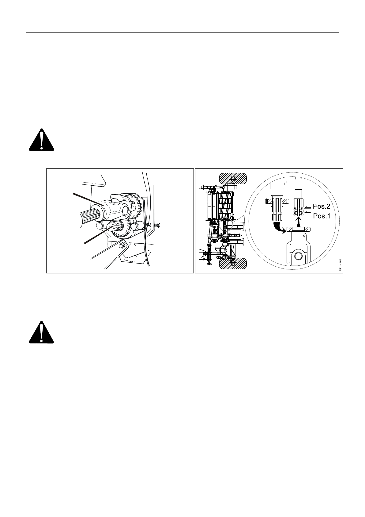
5. WORKING IN THE FIELD
PIGB-186X-05 FCT1360 0218
- 70 -
Fig. 5-5
PR12-0460
A
B
Fig. 5-6
The rotor
In case of blockage in the rotor, immediately change to neutral position and turn off
the power transmission. Hereby the auger and the feed intake stop immediately, and
you can obtain an overview of the situation.
To enable the feed rollers to pull the material out of the rotor, it must be disconnected
during reverse. The procedure is as follows:
1) Go to the machine when the power take-off has been disconnected and the engine
has stopped.
DANGER: Do not approach the machine until the rotating parts have come
to a complete stop and be aware that neutral position does not
guarantee that the feed intake will not start.
Fig. 5-5 2) Move the PTO shaft A for the rotor to the alternative pin in pos. 1 where the gear
Fig. 5-6 wheels are not in mesh. Thereby the rotor is not driven.
WARNING: It is important that the PTO shaft is NOT moved to pos. 2, where
the rotor rotates in the opposite direction. This position is only
used for grinding.
3) Connect the power take-off again at low number of rpm, move the reverse
function to reverse position and reverse the material out of the machine.
Fig. 5-5 4) After reversing disconnect the power take-off again, and when the rotor has
come to a complete stop, move the PTO shaft A for the rotor back to the pin B
for driving the rotor.
5) With the reverse function in neutral it is now normally possible to ”blow” the
chopped grass, which is in the rotor housing, out of the chute, unless this is also
blocked. In order to ”blow the rotor housing empty” it is necessary to increase
the number of revolutions to maximum.
6) Move the reverse function back to normal feed intake, and the work can be
resumed.
Page 71
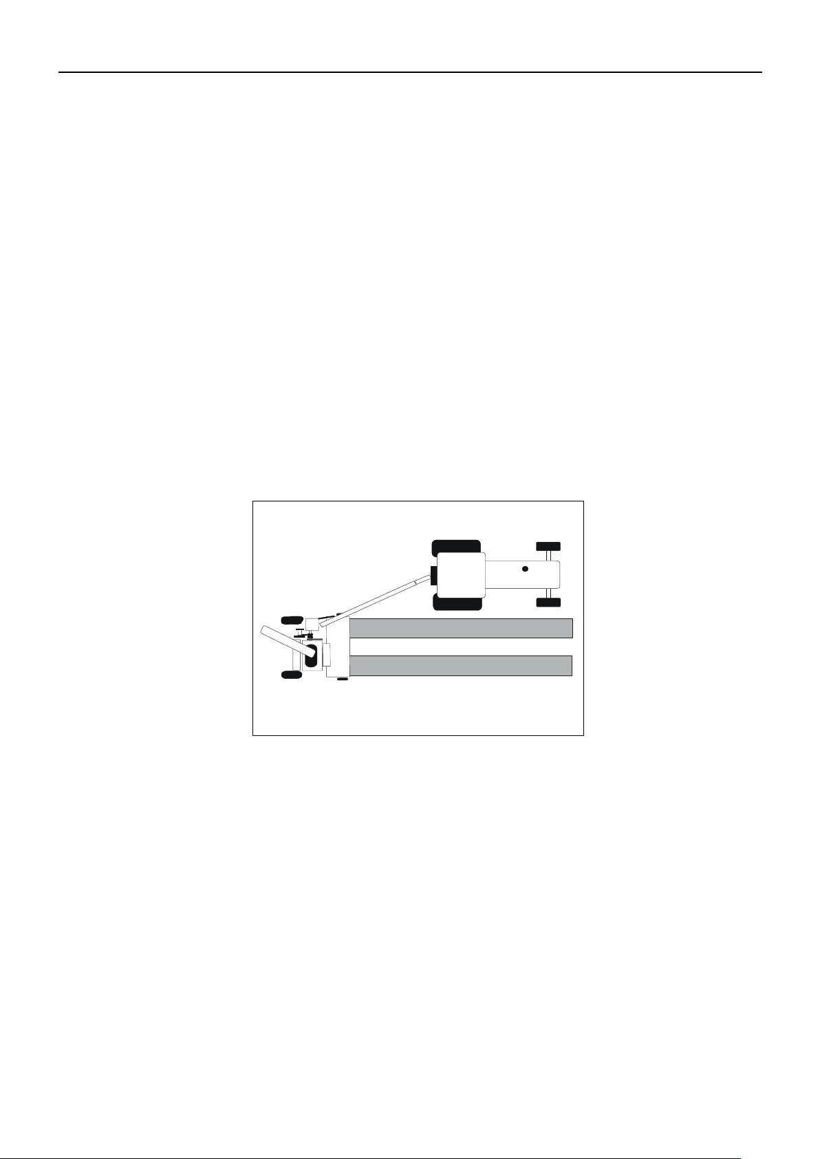
5. WORKING IN THE FIELD
PIGB-186X-05 FCT1360 0218
- 71 -
Fig. 5-7
P
R
1
1
-
1
1
1
5
AFTER WORK
When you have finished working with the machine, always place the reverse system
in neutral position. Hereby the belts on the V-belt drive are slackened.
MISCELLANEOUS
If you use ensiling agents, the safety instructions of these must be observed.
It is very important to protect the eyes.
7)
WORKING POSITIONS
The position of the drawbar is adjusted continuously with the hydraulic cylinder. To
avoid an obstacle etc. in the field you can easily adjust the position of the drawbar
during working since the drawbar is above the pick-up.
With the wide pick-up on the machine it is possible to work with the chopper in
several positions in relation to the tractor:
Fig. 5-7 1) The chopper picks up grass beside the tractor, working offset. The machine can
pick up wide single swaths and double swaths, which are very suitable for the
chopper. A good driving technique when loading into a trailer at the right-hand
side of the chopper.
Page 72
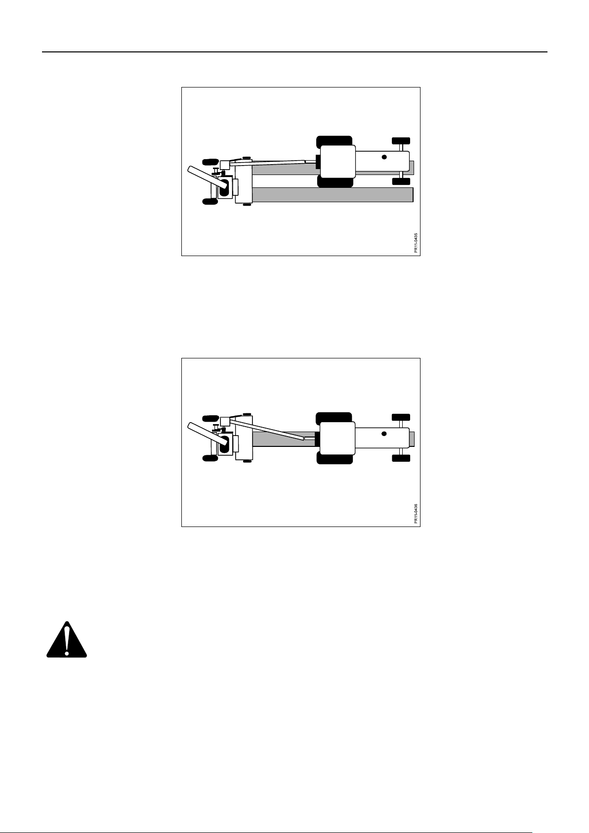
5. WORKING IN THE FIELD
PIGB-186X-05 FCT1360 0218
- 72 -
Fig. 5-8
Fig. 5-9
Fig. 5-8 2) The chopper now works semi-offset as the tractor drives with one set of wheels
between the swaths. This technique results in a straight drive line and is suitable
for unloading to both sides. The parallel driving tractor can get closer to the
chopper and it is easier to control the loading of the trailer.
Fig. 5-9 3) Here the chopper works in-line as the tractor drives over the swath. This
technique is of course very suitable for picking up single swaths as you avoid that
the tractor drives on the crop. The technique is still suitable for unloading to both
sides and brings the tractors close to each other.
CAUTION: The PTO shaft should work with a deviation of maximum 20.
For sharp turns to the right it is therefore recommended that the
drawbar is moved to transport position or a position
corresponding to working in-line (see Fig. 5-9.)
Page 73

6. MAINTENANCE
PIGB-186X-05 FCT1360 0218
- 73 -
A
Ø
Class: 8.8
MA [Nm]
Class: 10.9
MA [Nm]
Class:12.9
MA [Nm]
M 8
25
33
40
M 10
48
65
80
M 12
80
120
135
M 12x1,25
90
125
146
M 14
135
180
215
M 14x1,5
145
190
230
M 16
200
280
325
M 16x1,5
215
295
350
M 18
270
380
440
M 20
400
550
650
M 24
640
900
1100
M 24x1,5
690
960
1175
M 30
1300
1800
2300
6. MAINTENANCE
IN GENERAL
WARNING: When repairing or maintaining the machine it is especially
important to ensure correct personal safety. Therefore, always
park the tractor (if mounted) and the machine according to the
GENERAL SAFETY INSTRUCTIONS items 1-20 in the beginning
of this instruction manual.
IMPORTANT: Screws and bolts on your new machine must be retightened after
some hours of operation. This also applies if repairs have been
made.
Especially the bolts for the blades on the rotor must be retightened
carefully.
Torque measurement MA for bolts on the machine (if nothing else stated in this
instruction manual).
Page 74

PIGB-186X-05 FCT1360 0218
- 74 -
Fig. 6-1
P
R
1
1
-
0
2
4
3
PR80-0819
Guard
Fig. 6-2
PR11-0244
PR80-0820
Guard
GUARDS
6. MAINTENANCE
Fig. 6-1 When maintaining the machine you often need to open or remove guards.
Fig. 6-2 For safety reasons all guards have been equipped with a lock. The lock ensures that
the guard cannot be opened without tools. There are two different types of lock. Fig.
6-1 and 6-2 show the two locking principles and the corresponding transfers which
indicate and illustrate the locks on the machine.
REPLACEMENT OF BLADES
See description for replacement of blades in the rotor and the subsequent adjustment
in the section REPLACEMENT AND ADJUSTMENT OF BLADES in chapter 4
"ADJUSTMENTS".
Page 75

6. MAINTENANCE
PIGB-186X-05 FCT1360 0218
- 75 -
FCT 1360
Tyre dimension
Tyre pressure [bar]
Machine, standard
19.0/45-17/10
2.25
Machine, option
14.0/65-16/10
2.80
Rubber wheels for pick-up, optional
equipment
3.50-6/4
3.00
TYRE PRESSURE
FCT 1360 is as standard equipped with wide low profile tyres which provide a good
carrying capacity and thus a low ground pressure.
The below table indicates the recommended tyre pressure. The machine is delivered
from the factory with these pressures.
A reduced tyre pressure for the machine can be used in extreme cases when driving
in areas where extra large carrying capacity is required (meadows, sandy areas or
the like)
CAUTION: Check the tyre pressure regularly and make sure that the wheel-
fixing bolts are tightened correctly.
Page 76

6. MAINTENANCE
PIGB-186X-05 FCT1360 0218
- 76 -
Fig. 6-3
FRICTION CLUTCH
Fig. 6-3 In order to ensure a long life for your tractor and machine, the machine is delivered
with a friction clutch on the front PTO drive shaft. The figure illustrates how the
clutch protects the transmission against high torque peaks and at the same time is
capable of transmitting the torque while it is briefly in function (slips).
In order to ensure that the clutch works as intended it must be “aired” at regular
intervals as dirt and moisture may cause the clutch to get “stuck”.
Page 77

6. MAINTENANCE
PIGB-186X-05 FCT1360 0218
- 77 -
Fig. 6-4
Fig. 6-4 Before the start of a new machine and after a long period of standstill, e.g. winter
storage, the clutch is "aired" in the following way:
1) The six nuts A on the flange are tightened. Hereby the springs B are
compressed so that they do not press on the clutch plates C and the clutch can
rotate freely.
2) Let the clutch rotate for 30 seconds. This removes dirt and possible rust on
the plates.
3) The nuts A are loosened again until they are at level with the threads of the
bolts, and the springs B can press on the clutch plates C.
Page 78
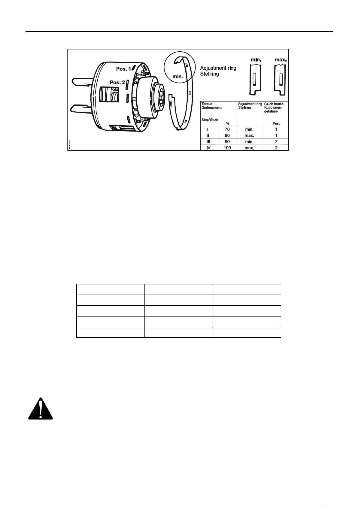
6. MAINTENANCE
PIGB-186X-05 FCT1360 0218
- 78 -
PTO
Torque
Adjustment
1000
2700 Nm
Step I
1000
3000 Nm
Step II
1000
3300 Nm
Step III
1000
3600 Nm
Step lV
Fig. 6-5
Fig. 6-5 The torque in the friction clutch is adjustable. However, you should not change the
factory-set adjustment until you have contacted the dealer or the factory’s Service
Department.
The friction clutch has 4 different torque adjustments. The adjustment can be
changed by turning the adjustment ring D and by choosing between 2 different
positions in the clutch housing.
1. The adjustment ring has a minimum and a maximum position.
2. The clutch housing has two different sets of slots E in the height into which the
adjustment ring D can be mounted, pos. 1 and pos. 2.
TORQUE ADJUSTMENT GUIDE
From the factory the clutch is delivered with adjustment II, corresponding to 3000 Nm
and should not be adjusted higher!
Adjustment of the torque can only be made when the nuts A (on Fig. 6-4) are
tightened. After the adjustment the nuts are loosened again to the end of the bolt.
WARNING: If the clutch is overloaded by slipping for some time, it will get
heated and thus be worn quickly.
Overheating will damage the friction plates. If the clutch is
blocked or partly put out of function in other ways, the factory
guarantee will be discontinued.
Page 79

PIGB-186X-05 FCT1360 0218
- 79 -
FUSES
Fig. 6-8
6. MAINTENANCE
Fig. 6-8 There are two 10A fuses in the control system on the machine. Only replace the
fuses by fuses with the same power value. Servicing, except replacement of fuses,
must always be performed by an authorised KONGSKILDE dealer / service
technician.
WARNING: Never mount fuses with a higher power value. The control system
may be damaged. If fuses blow there is an error in the electric
system.
Page 80

PIGB-186X-05 FCT1360 0218
- 80 -
Fig. 6-9
PR12-0240a
A
Fig. 6-10
MISCELLANEOUS
ROLLERS
6. MAINTENANCE
Fig. 6-9 The upper rear feed roller, the smooth roller A, should be secured against formation
of rust on the surface. If the machine is not in use in a period of more than one day,
the whole surface should be lubricated with a thin coat of oil.
CHAIN TIGHTENER FOR PICK-UP AUGER
Fig. 6-10 Two bolts A are loosened after which the eccentric B can be turned with a
screwdriver or the like. It is turned in + direction for tightening and in – direction for
loosening.
CAUTION: It should always be possible to move the chain at least 20 mm
up and down in the middle to make sure that it is not too tight.
Page 81
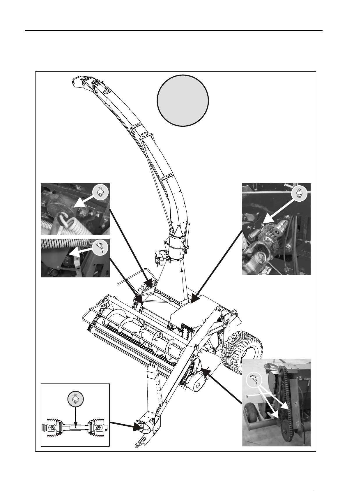
PIGB-186X-05 FCT1360 0218
- 81 -
7. GREASING
PR11-1825
10h
7. GREASING
Page 82

PIGB-186X-05 FCT1360 0218
- 82 -
PR11-1871
50h
7. GREASING
Page 83
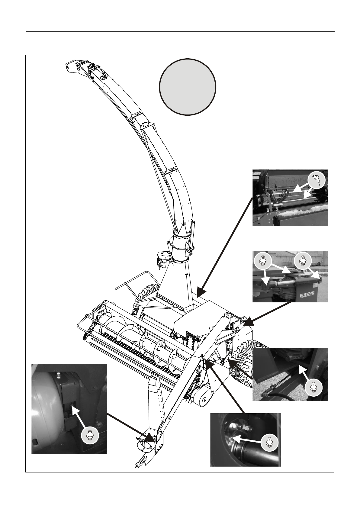
PIGB-186X-05 FCT1360 0218
- 83 -
PR11-1872
50h
7. GREASING
Page 84

7. GREASING
PIGB-186X-05 FCT1360 0218
- 84 -
PR11-1830
50h
Page 85

7. GREASING
PIGB-186X-05 FCT1360 0218
- 85 -
PR11-1873
50h
Page 86
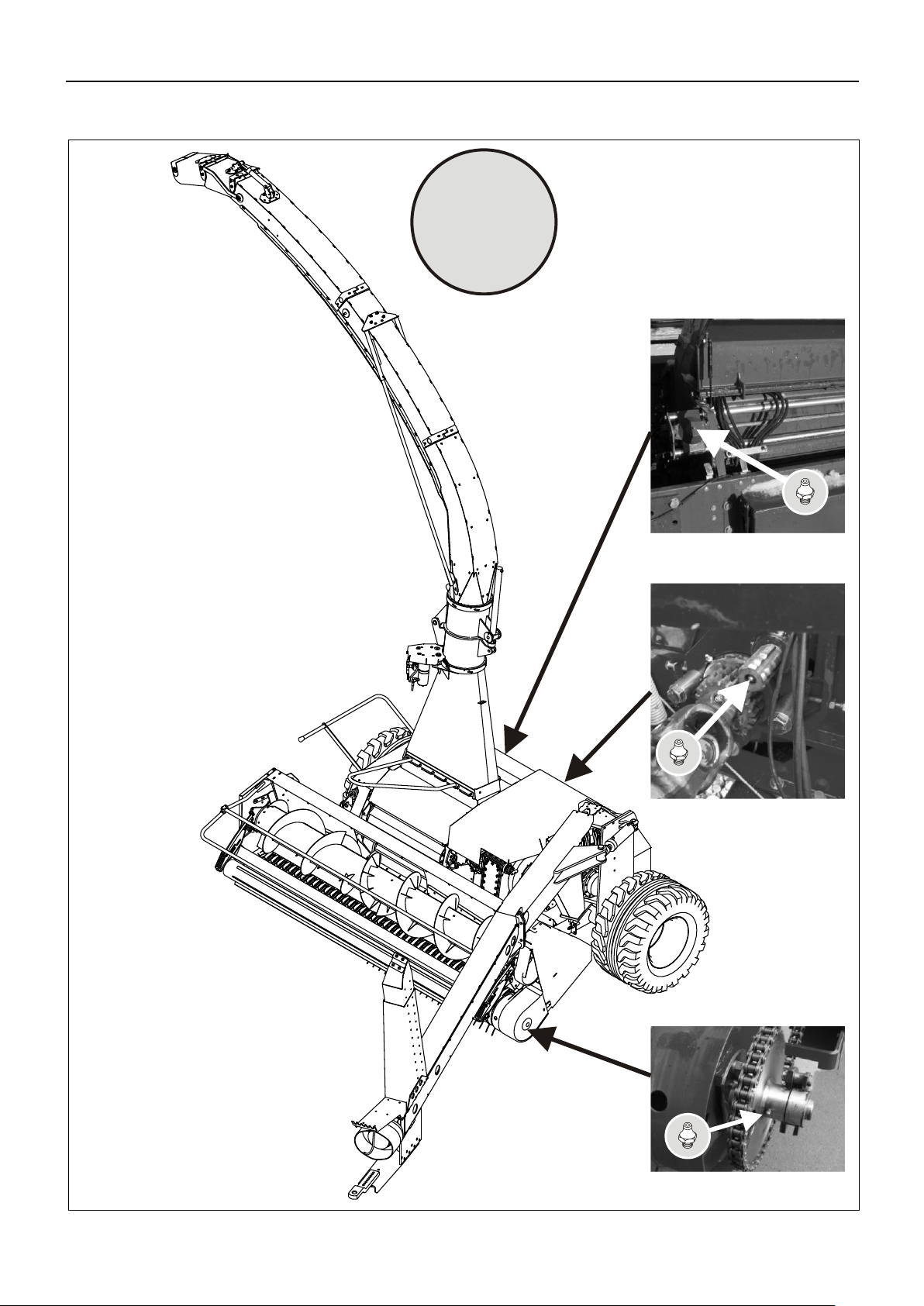
7. GREASING
PIGB-186X-05 FCT1360 0218
- 86 -
PR11-1874
250h
Page 87

PIGB-186X-05 FCT1360 0218
- 87 -
PR11-1829
250h
7. GREASING
Page 88

PIGB-186X-05 FCT1360 0218
- 88 -
PR11-1875
50 h
10 h
10 h
100 h
7. GREASING
Page 89
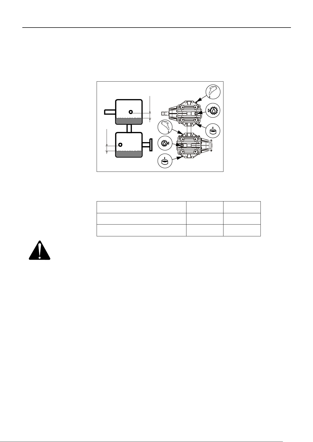
7. GREASING
PIGB-186X-05 FCT1360 0218
- 89 -
Oil content
Quality
Swivel gearbox, upper part
3.5 l
85W-140
Swivel gearbox, lower part
3.5 l
85W-140
PR11-1832
3,5 L Oil
30 mm
25 mm
3,5 L Oil
Fig. 7-1
OIL IN GEARBOXES
Swivel gearbox
Fig. 7-1
IMPORTANT: The oil level must in the upper and lower part be 30 and 25 mm lower
Oil change: After the first 10 working hours and then once a year.
than the check plugs at the side of the swivel gearbox, as shown on
the figure.
Page 90
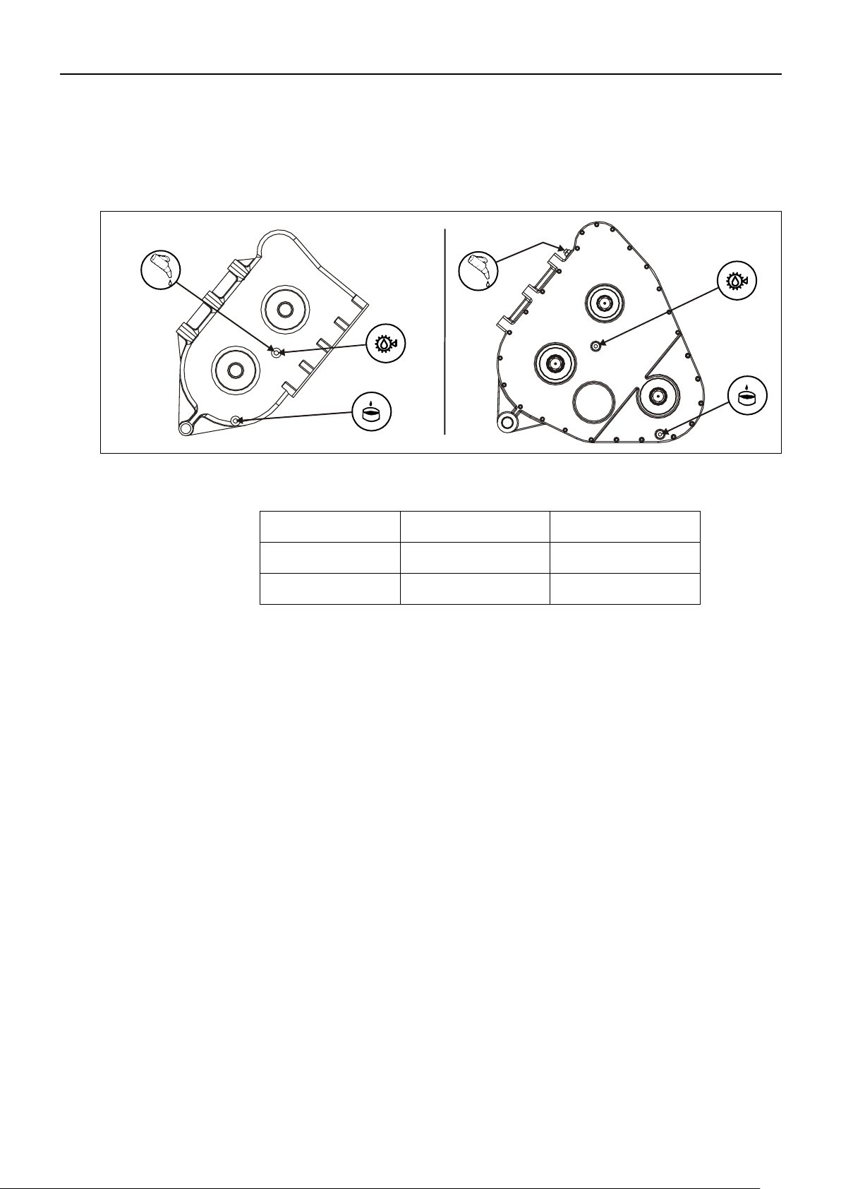
7. GREASING
PIGB-186X-05 FCT1360 0218
- 90 -
Oil content
Quality
Harvest gear 1
2,4 l
80W-90
Harvest gear 2
3,5 l
80W-90
Fig. 7-2
PR11-1876
Gear 1
Gear 2
Harvest gear
There are two different types of the harvestgear. Gear 1 has a chaindrive on the
exterior
Fig. 7-2
The oil level is checked through an inspection glass. The correct position of the
gearbox during inspection and filling of oil is neutral position.
Oil change: After the first 10 working hours and then once a year.
Page 91

8. STORAGE (WINTER STORAGE)
PIGB-186X-05 FCT1360 0218
- 91 -
8. STORAGE (WINTER STORAGE)
When the season is over, the preparation for winter storage should be made
immediately after. First, clean the machine thoroughly. Dust and dirt absorb moisture
and moisture increases the formation of rust.
CAUTION: Be careful when cleaning with a high pressure cleaner. Never
spray directly on the bearings and grease all grease points
carefully after cleaning so that possible water is pressed out of
the bearings.
IMPORTANT: Grease all grease points after cleaning the machine.
The following points are instructions how to prepare for winter storage.
Check the machine for wear and other defects – note down the necessary parts
you will need before the next season and order the spare parts.
Dismount the PTO drive shafts, lubricate the profile tubes and keep them in a dry
place.
Spray the machine with a thin coat of rust-preventing oil. This is especially
important on the parts polished with use.
Change the oil in the gearboxes.
Store the machine in a ventilated engine house.
Lay up the machine to unload the tyres.
Page 92

PIGB-186X-05 FCT1360 0218
- 92 -
9. SPARE PARTS ORDER
9. SPARE PARTS ORDER
When ordering spare parts, please state machine type and serial number.
This information is printed on the machine plate. We request you to write this
information on the first page in the spare parts book supplied with the machine as
soon as possible so that you have the information at hand when ordering spare parts.
Page 93

PIGB-186X-05 FCT1360 0218
- 93 -
10. MACHINE DISPOSAL
10. MACHINE DISPOSAL
When the machine is worn-out it must be disposed of in a proper way.
Observe the following:
The machine must not be placed somewhere outside.
Gearboxes, cylinders, and hoses must be emptied of oil. These oils must be
handed over to a destruction company.
Disassemble the machine and separate the individual parts, e.g. PTO drive
shafts, tyres, hydraulic components etc.
Hand over the usable parts to an authorised recycling centre. The large scrapping
parts are handed over to an authorised breaker's yard.
Page 94
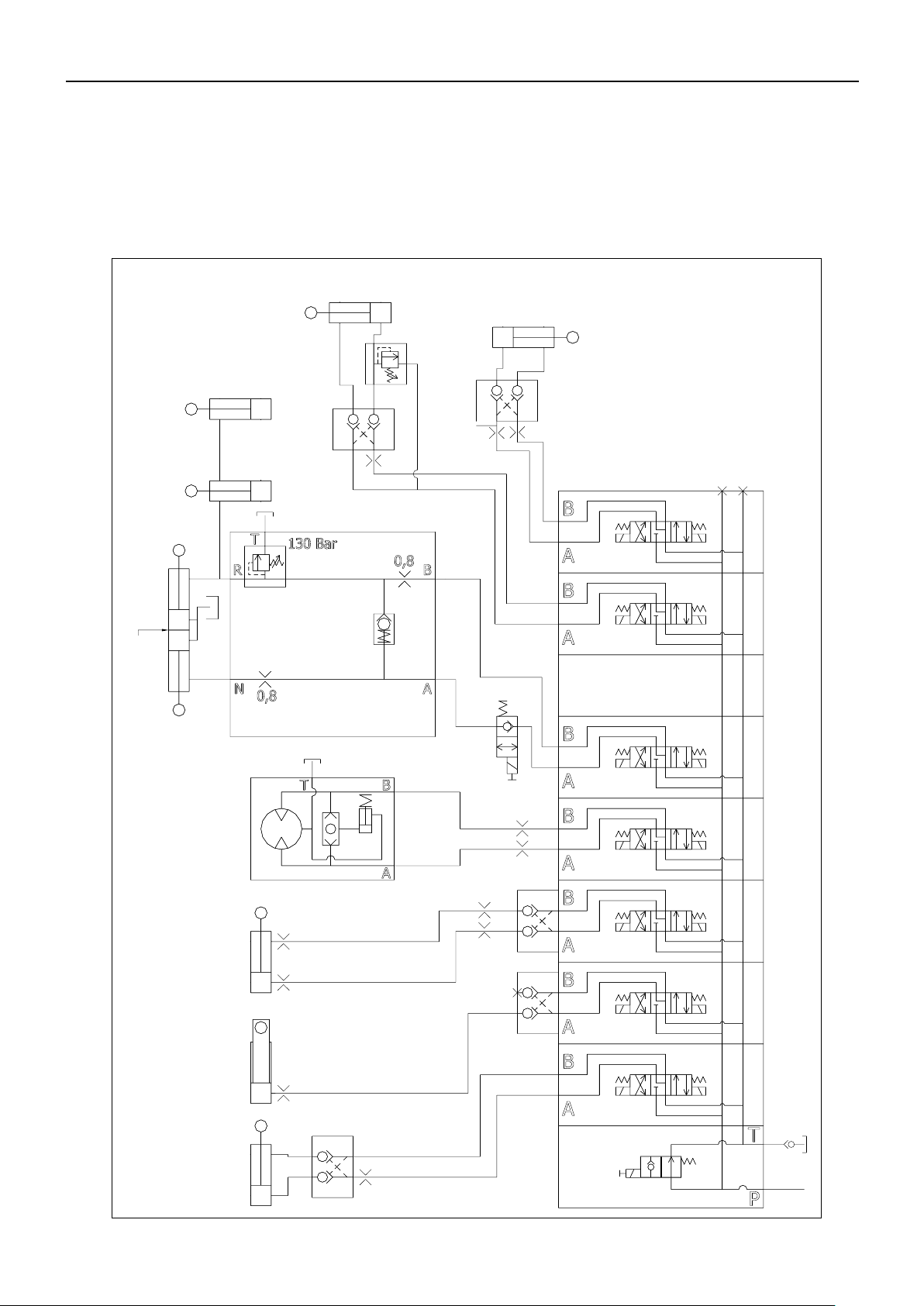
PIGB-186X-05 FCT1360 0218
- 94 -
PR11-1760
V0
1,5
1,5
V1
C1: Turn
drawbar
C2: PU lift
V2
0,8
0,8
0,8
0,8
V3
C3: Deflector
up/down
M1: Swivel
chute w. brake
0,8
0,8
V4
V5
V6
(NC)
V10
V11
Neutral
Reverse
C4: Intake section
C5
C6
Lift auger and roller
Foldable chute (extra equipment)
Autohitch (extra equipment)
C8
50 Bar
C7
0,8
1,5
1,5
11. MISCELLANEOUS
11. MISCELLANEOUS
HYDRAULIC DIAGRAM FOR FCT 1360
Page 95

11. MISCELLANEOUS
PIGB-186X-05 FCT1360 0218
- 95 -
PR11-1761
CONTROL SYSTEM
Page 96

PIGB-186X-05 FCT1360 0218
- 96 -
CONTROL BOX
PR11-1762
11. MISCELLANEOUS
Page 97

PIGB-186X-05 FCT1360 0218
- 97 -
PR11-1763
Gland positions - L (left)
4
6
2
Power
Multicable
Cable MD
Gland positions - Z (bottom)
7
8
10
14
16
18
13
15 17
5
6
9
3
4
1
2
12
11
JP 1
JP 7
JP 8
JP 4
JP 3
JP 5
JP 2
JP 1
JP 6
JP 9
11. MISCELLANEOUS
CONTROL UNIT ON THE MACHINE
Page 98

PIGB-186X-05 FCT1360 0218
- 98 -
PR11-1764
Prewired
(Y/N)
Function
category
Functional description
Multi-
cable
wire
n°
Souriau
connection
Connection
print PCB
n°
IN
In-Dig In-Ana Out-D Out-A
Connection
print PCB n°
OUT
Signal
terminal
wire
colour
Positive
Terminal
wire
colour
Negative
Terminal
wire
colour
Length
(m)
Gland
Position
Label Comment
Joystick LED 9
Led Power ON - System Power indicator
Mounted on joystick PCB
Internal power
0 volt power supply for Metal detector
JP8_7
Blue
Souriau plug - pin A
Internal power
+12 volt power supply Metal detector
(ON/OFF switch via main relay)
JP2_7
Red
Souriau plug - pin B
MD input
V5a input from MD
JP6_3
Orange
Double function MD/Onboard - Souriau plug -
pin C
MD input
V0 input from MD
JP9_1 Yellow
Double function MD/Onboard - Souriau plug -
pin D
Joystick power
0 volt power supply
1
A
JP6_1
Joystick power
+12 volt power supply (main relay)
2
B
JP2_1
Multiple cores to ensure power supply
Joystick power
+12 volt power supply (main relay)
3
C
JP2_2
Joystick power
+12 volt power supply (main relay)
4
D
JP2_3
Joystick power
+12 volt power supply (main relay)
5
E
JP2_4
Joystick power
+12 volt power supply (main relay)
6
F
JP2_5
Joystick power
+12 volt power supply (main relay)
7
G
JP2_6
Joystick Led 7
MD ON Green LED placed in Joystick Cabinet
8
H
Status LED from MD -Souriau plug - pin E
Coverage for LED when delivered w/o MD
Joystick Led 8
MD STOP Red LED placed in Joystick Cabinet
9
J
Status LED from MD -Souriau plug - pin E
Coverage for LED when delivered w/o MD
Clutch Guard - Yellow LED placed in Joystick
10
K
Status LED from MD - Souriau plug - pin G
Joystick sw 10
FCT Onboard ON/OFF (main relay)
11
L
JP6_2
Supply for JP1 & JP2
Joystick 6.3 / (6.7) Joystick Left V4B /(V1A)
12
M
JP9_4
2
JP3_3/(5)
Brown
Blue
1,0
Z11 / (Z18) V4B /(V1A) 2x0,75mm² with valve connector
Y
Joystick 6.4 / (6.8) Joystick Right V4A / (V1B)
13
N
JP9_5
2
JP3_4/(6)
Brown
Blue
1,0
Z12 / (Z17) V4A / (V1B) 2x0,75mm² with valve connector
Y
Joystick 6.2 / (6.6) Joystick Down V3B / (V2A)
14
P
JP9_7
2
JP3_7/(9)
Brown
Blue
1,0
Z13 / (Z16) V3B / (V2A) 2x0,75mm² with valve connector
Y
Joystick 6.1 / (6.5) Joystick Up V3A / (V2B)
15
R
JP9_8
2
JP3_8/(10) Brown
Blue
1,0
Z14 / (Z15) V3A / (V2B) 2x0,75mm² with valve connector
Joystick top button Joystick top button primary/(secondary) function
16
S
JP9_2
Y
Joystick sw 5.2
V6 Valve
17
T
JP4_8
1
JP5_8
Brown
Blue
1,0
Z9
V6
2x0,75mm² with valve connector
Y
Joystick sw 5.1
V5a Valve
18
U
JP6_4
1
JP5_10
Brown
Blue
1,0
Z8
V5a
2x0,75mm² with valve connector
Y
Joystick sw 4
V5b Valve
19
V
JP4_9
1
JP5_9
Brown
Blue
1,0
Z7
V5b
2x0,75mm² with valve connector
Y
Joystick sw 3.1
V12a Valve
20
W
JP4_1
1
JP5_1
Brown
Blue
1,0
Z2
V12a
2x0,75mm² with valve connector
Y
Joystick sw 3.2
V12b Valve
21
X
JP4_2
1
JP5_2
Brown
Blue
1,0
Z1
V12b
2x0,75mm² with valve connector
Y
Joystick sw 2.1
V11a Valve
22
Y
JP4_3
1
JP5_3
Brown
Blue
1,0
Z4
V11a
2x0,75mm² with valve connector
Y
Joystick sw 2.2
V11b Valve
23
Z
JP4_4
1
JP5_4
Brown
Blue
1,0
Z3
V11b
2x0,75mm² with valve connector
Y
Joystick sw 1.1
V10a Valve
24
a
JP4_5
1
JP5_5
Brown
Blue
1,0
Z6
V10a
2x0,75mm² with valve connector
Y
Joystick sw 1.2
V10b Valve
25
b
JP4_6
1
JP5_6
Brown
Blue
1,0
Z5
V10b
2x0,75mm² with valve connector
Y
Internal
V0 Valve - Master valve (ex. V6)
1
JP5_1
Brown
Blue
1,0
Z10
V0
2x0,75mm² with valve connector
Y
Power
Power cable
10,0
L2
4x2,5mm² with Cobo plug
Y
Connection
Multicable
10,0
L4
25x0,75mm
2
w/Souriau connection
Y
Fuse
Fuse 10 Amp for +12V
F1
Fuse
Fuse 10 Amp for -0V
F2
Wire connections
Signal type
11. MISCELLANEOUS
CONTROL UNIT ON MACHINE, WIRING SYSTEM
Page 99

12. WARRANTY
12. WARRANTY
Your machine is warranted according to legal rights in your country and the
contractual agreement with the selling dealer. No warranty shall, however, apply if
the machine has not been used, adjusted and maintained according to the
instructions given in this operator's manual.
It is prohibited to carry out any modifications to the machine unless specifically
authorized, in writing, by a NEW HOLLAND representative.
PIGB-186X-05 FCT1360 0218
Page 100

Maskine: La máquina: Masin:
Maschine: Maszyna: Stroj:
Machine: Машината: Η μηχανή:
Machine: Gép: Máquina:
La macchina: Stroj: Il-magna:
Machine: Mašina: Mašīna:
Maskin: Stroj:
Laite: Maşina:
Model/Type: FCT 1360
Designation: Harvester
Serial:
EF-overensstemmelseserklæring/ EG-Konformitätserklärung/ EC Declaration of Conformity/ Déclaration CE de
conformité/ Dichiarazione CE di conformita/ EG Verklaring van Overeenstemming/ EG-försäkran om överensstämmelse/
EY-vaatimustenmukaisuusvakuutus/ Declaración de conformidad CE/ Deklaracja Zgodności WE./ Декларация за
съответствие EO/ EK Megfelelőségi Nyilatkozat /ES Prohlášení o shodě/ EB Atitikties deklaracija/ ES prehlásenie o
zhode/ Declaraţia de conformitate CE/ Vastavuse Deklaratsioon EÜ /ES Izjava o skladnosti/ Δήλωση πιστότητας EK/
Declaração de fidelidade CE/ Dikjarazzjoni ta’ Konformità tal-KE/ EK Atbilstības deklarācija/
Fabrikant/ Hersteller/ Manufacturer/ Fabricant/ Produttore/ Fabrikant/ Fabrikant/ Valmistaja/ Fabricante/ Producent/
Производител/ Gyártó/ Výrobce/ Gamintojas/ Výrobca/ Producător/ Tootja/ Proizvajalec/ Κατασκευαστής/ Fabricante/
Fabbrikant/ Ražotājs
CNH INDUSTRIAL BELGIUM N.V.
Leon Claeysstraat 3a, 8210 Zedelgem, BELGIUM
Repræsenteret af Antoon Vermeulen, Leon Claeysstraat 3A, B8210 Zedelgem (Belgien), som også har tilladelse til at
indsamle teknisk dokumentation / vertreten durch Antoon Vermeulen, Leon Claeysstraat 3A, B8210 Zedelgem (Belgium),
der auch autorisiert ist, die technische Akte zu erarbeiten / represented by Antoon Vermeulen, Leon Claeysstraat 3A,
B8210 Zedelgem (Belgium), who is also authorised to compile the Technical File / Répresentés par Antoon Vermeulen,
Leon Claeysstraat 3A, B8210 Zedelgem (Belgique), également autorisé à constituer le dossier technique / rappresentati
da Antoon Vermeulen, Leon Claeysstraat 3A, B8210 Zedelgem (Belgio), autorizzato a compilare il File tecnico /
vertegenwoordigd door Antoon Vermeulen, Leon Claeysstraat 3A, B8210 Zedelgem (Belgium), die tevens is gemachtigd
om het Technisch Bestand samen te stellen / representerade av Antoon Vermeulen, Leon Claeysstraat 3A, B8210
Zedelgem (Belgien), som också har behörighet att sammanställa den tekniska dokumentationen / edustajamme Antoon
Vermeulenin, osoite Leon Claeysstraat 3A, B8210 Zedelgem (Belgium) välityksellä, jolla on myös oikeus laatia tekninen
tiedosto / representados por Antoon Vermeulen, Leon Claeysstraat 3A, B8210 Zedelgem (Bélgica), quien además está
autorizado para recopilar el documento técnico / której przedstawicielem jest Antoon Vermeulen, Leon Claeysstraat 3A,
B8210 Zedelgem (Belgia), który jest również upoważniony do sporządzania dokumentacji technicznej / представлявани
от Антоон Вермьолен, Leon Claeysstraat 3A, B8210 Zedelgem (Белгия), с упълномощение също да състави
Техническото досие / akiket képvisel: Antoon Vermeulen, Leon Claeysstraat 3A, B8210 Zedelgem (Belgium), aki
szintén jogosult a műszaki dokumentumok összeállítására / v zastoupení Antoon Vermeulen, Leon Claeysstraat 3A,
B8210 Zedelgem (Belgium), s autorizací k tvorbě technického souboru / atstovaujami Antoon Vermeulen, Leon
Claeysstraat 3A, B8210 Zedelgem (Belgija), taip pat turintis teisę sudaryti technines bylas / v zastúpení Antoonom
Vermeulenom, Leon Claeysstraat 3A, B8210 Zedelgem (Belgicko), ktorý je oprávnený zostavovať technickú
dokumentáciu / reprezentaţi de Antoon Vermeulen, Leon Claeysstraat 3A, B8210 Zedelgem (Belgia), care este, de
asemenea, autorizat să compileze dosarul ethnic / esindajatega Antoon Vermeulen, Leon Claeysstraat 3A, B8210
Zedelgem (Belgia), kellel on samuti luba tehnilise faili koostamiseks / ki nas zastopa Antoon Vermeulen, Leon
Claeysstraat 3A, B8210 Zedelgem (Belgija), ki je pooblaščen tudi za sestavo tehnične dokumentacije /
εκπροσωπούμενοι από τον Antoon Vermeulen, Leon Claeysstraat 3A, B8210 Zedelgem (Βέλγιο), με εξουσιοδότηση και
για τη σύνταξη του Τεχνικού φακέλου / representados por Antoon Vermeulen, Leon Claeysstraat 3A, B8210 Zedelgem
(Bélgica), que também tem autorização para compilar o Ficheiro Técnico / irrappreżentata minn Antoon Vermeulen Leon
Claeysstraat 3a, B8210 Zedelgem (Belġju), min huwa wkoll awtorizzat li tiġbor l-Fajl Tekniku / Antoon Vermeulen, Leon
Claeysstraat 3A, B8210, Zedelgem (Belgium), pārstāvēti, kas ir pilnvarots arī sastādīt tehnisko reģistru
Erklærer hermed, at/ Erklären hiermit, daß/ Hereby declare that/ Déclare par la présente que/ Dichiara che/ Verklaren
hierbij dat/ Försäkrar härmed, att/ Vakuuttaa täten, että tuote/ Por el presente declara que/ Niniejszym deklaruje, że/
Декларирам, че/ Az alábbiakban kijelentem, hogy/ Tímto prohlašuje, že/ Deklaruoja, kad/ Týmto prehlasujeme, že/ Prin
prezenta declar că/ Alljärgnevaga deklareerib, et/ Izjavljamo, da je/ Με το παρόν δηλώνω ότι/ Abaixo declara que /
Jiddikjaraw li / Apstiprinu, ka
- er i overensstemmelse med Maskindirektivets bestemmelser (Direktiv 2006/42/EF) og hvis relevant også
bestemmelserne i EMC-direktivet 2014/30/EU.
- In übereinstimmung mit den Bestimmungen der Maschinen-Richtlinie 2006/42/EG und wenn erforderlich auch mit der
EMC-Richtlinie 2014/30/EU hergestellt wurde.
- is in conformity with the provisions of the Machinery Directive 2006/42/EC and if relevant also the provisions of the
EMC Directive 2014/30/EU.
 Loading...