

Page 1
300FS Harrows
Flex Drag & Spiral Roller Combi
Kongskilde
300 FS
ASSEMBLY INSTRUCTIONS
& OPERATING GUIDE
Page 2

INDEX:
Introduction ..............................................................................................................….........................2
Pre Assembly Tips .............................................................................................…................................3
3 Bar Spike Drag Harrow Sections Assembly ......................................................................................4
Spiral Bar Rota-Harrows Assembly.......................................................................................................8
Adjustments / Precautions ............................................................................................................…..12
Field Settings ...............................................................................................................................…....13
Maintenance ........................................................................................................................................15
OEM Mounting Kit .............................................................................................................................15
Parts List Assembly Diagram ...............................................................................See Separate Booklet
Mounting Pattern Diagrams for Cultivators ........................................................See Separate Booklet
INTRODUCTION:
Kongskilde 300FS Combi Harrows have been developed as a levelling attachment for field cultivators.
When properly adjusted the Harrow will help to prepare a level surface for planting in various field
conditions and soil types.
To achieve this, the 300FS Harrow combines a 3-Bar Flex Drag-Spike Harrow with a Single Offset
Spiral Bar Rota Harrow.
This booklet has been developed to assist you in assembling your Combi Harrow Kit for the Kongskilde
Field Cultivator Model VT2800. Harrow mounting patterns for each cultivator size is provided in a
separate booklet.
2
Page 3
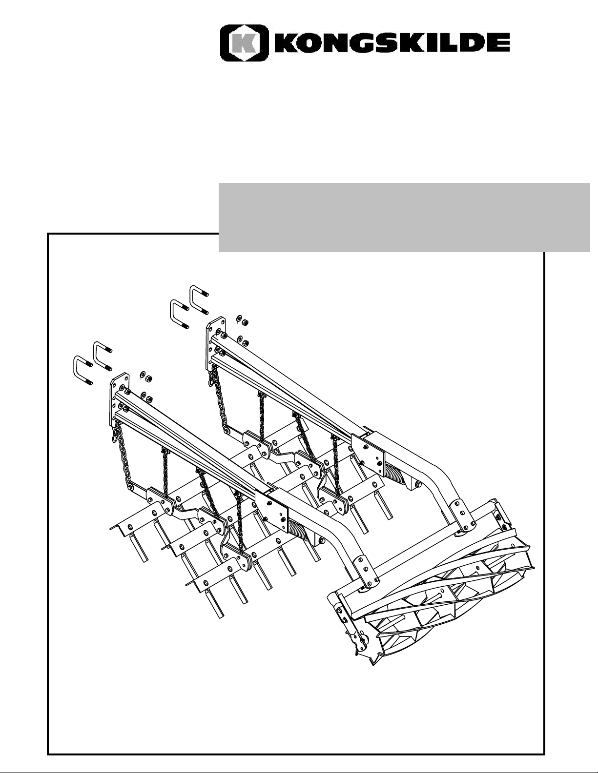
PRE ASSEMBLY TIPS:
Prior to assembling the Combi Harrows, the cultivator should be carefully unfolded and lowered to the
ground, (resting on the tines), on a flat level area.
Combi Harrows are really two separate harrow systems that share a common hanger arm and should
therefore be assembled in three stages:
1) Assemble the 3 Bar Drag Harrows and position behind the machine.
2) Mount the hanger arms and attach the drag harrows to them.
3) Assemble the Spiral Bar Rota Harrows and attach to the ends of the hanger arms.
(Refer to the detailed assembly instructions for each of the above stages)
The combi harrows are shipped from the factory in component form. They are packed together and
include: the pre-assembled spike bars; the carrier arms; the rollers, roller frames, and roller arms; and
the assembly hardware bags.
Refer to the parts list booklet for a detailed breakdown and description of the assembled components.
This booklet will help you to identify the items required for proper assembly.
NOTE: Position the harrow mounting bracket holes according to the tine in use VTM or VTH
Use Top Holes On Harrow
Mountin Bracket When
Use Bottom Holes On
Harrow Mountin Bracket
When Using VTM Tines
Harrow mounting Braket
VTM
20"
Using VTH Tines
VTH
24"
3
Page 4
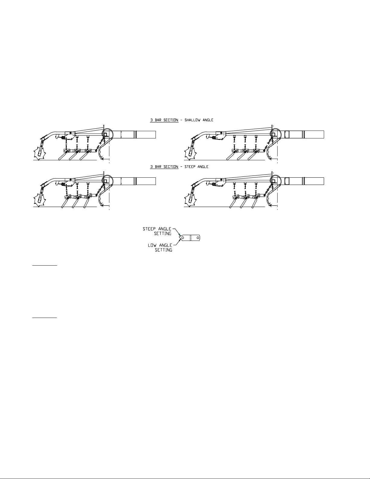
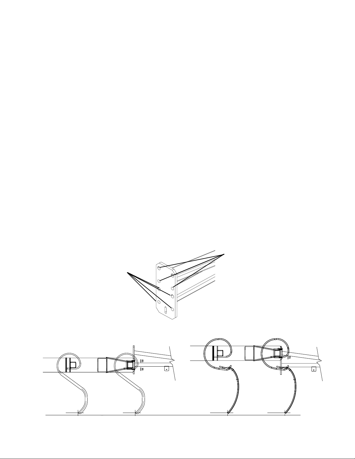
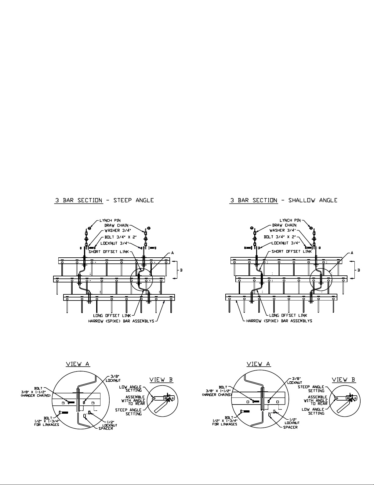
ASSEMBLY INSTRUCTIONS: Working Angle of 3-Bar Drag Harrow
As an added feature, the straight and offset joiner links of the 3 bar drag sections have been double
sheared on one end with two different angle cuts. This gives you the opportunity to set the spikes bars
to run at a shallow angle of about 30° for levelling in heavy residue or lighter soils, or set at a steeper
angle of about 45° for breaking clods and lumps in heavier soils. The harrows come pre-assembled
from the factory on the steep angle setting. However, If you want to change to the shallow angle setting you must flip the offest brackets over on all sections before starting the assembly, as all sections
must be set the same way.
See Diagrams & Notes below.
NOTE 1: Depending on the setting chosen, the harrow bars may be flipped over and offset in the op
posite direction to the diagrams shown in the harrow layout booklets. For example; a right offset joiner
link set in the shallow angle position becomes a left offset link when flipped over into the steep angle
position.
NOTE 2: All offset brackets must be assembled to work at the same angle; either shallow or steep. You
do not have the option to mix one angle setting with another. Therefore, you cannot set the front row
to run at the steep angle and the rear 2 rows to run shallow. All spike bars must work at the same angle
to allow for proper spacing between the spikes.
-
4
Page 5
ASSEMBLY INSTRUCTIONS: Drag Harrow Sections
1. Before starting, be sure you have the correct quantity and size of drag harrow bundles and spiral
bar rollers for the machine that is being assembled. The size combinations and mounting location for
each machine are shown in the harrow layout booklet provided for each model of cultivator.
2. Each harrow section may be assembled separately and then positioned behind the cultivator.
However these harrow sections are very heavy and awkward to move when completely assembled. You
may want to position them behind the cultivator first and then complete the assembly.
3. Lay the 3 bar harrow sections out behind the cultivator and assemble the offset joiner links and
chains according to the layout diagrams below. Start with the Centre Section first, then assemble the
right and left hand wing sections.
5
Page 6

4. Note: On some cultivator models you will need to mount a special extension to the ends of the
spike bars. Mark the locations for the bolt holes, or clampthe extensions to the spike bar and use them
as a guide for drilling. Secure with bolts and locknuts supplied. See detail below.
5. Mount the carrier arms to the rear toolbar of the cultivator centre section with the 5/8" U-bolts,
washers and locknuts provided. Always start in the centre of the machine and work out to the wings to
keep the spacing even between the harrow sections.Position 4 of the arms above the chain brackets on
the drag harrow assemblies according to the sample diagram below.
NOTE: Only four of the arms (A) below are used to hang the drag harrow sections. The extra pair of
arms (B) shown are required for mounting the rota harrows only. If required, these are positioned in
between the arms for mounting the drag harrows as shown. Pay close attention to the layout diagrams
provided with each machine for correct placement of the harrow arms.
6
Page 7

6. The pull chains are connected to a slot in the bottom of the harrow mounting bracket.
7. Connect the pull chains to the draw brackets by inserting one of the chain links thru the slot in
the bracket and securing with the lynch pin provided. The length of the pull chains may be adjusted as
required to obtain optimal levelling and grooming of the soil surface. Initially they can be set at about
the 3rd link. (See the field settings section later in this manual. )
8. Connect the transport chains to the tabs on the bottom side of the carrier arms with the bolts,
washers and locknuts provided.
Note that there are only 2 tabs on the short arms. An extra hole is provided on the harrow mounting
bracket for the 3rd hanger chain. The length of these chains may be adjusted according to desired
transport height, (about 12 links to start).
Set at
12 Links
9. When the centre section harrow assembly is complete, mount the carrier arms and harrow sec
tions to the wings in a similar manner, repeating points 3 to 8 again for the wing sections.
NOTE: To avoid interference between the harrow sections there should be a minimum of 4" between
the ends of each harrow bar.
Set at the
3rd Link
-
10. Ensure that all bolts are tight.
7
Page 8

Assembling and Mounting the Spiral Bar Rollers:
1. After completing the assembly of the drag harrow sections and all sections have been mounted
to the hanger arms, start assembling the components for the rota harrows.
Once again, begin with the centre section and move out to the wings.
Springs:
2. The Harrow Arms and Spring Assemblies for the rollers are pre-assembled at the factory.
However, for repair or replacement of the spring assemblies, assemble the spring insert into the open
end of the spring with the wrench tab pointing outwards. Use a wrench to screw the insert down inside
the spring until the stop tab at the end of the threads contacts the end coil of the spring. See diagram
below:
3. Mount the spring assembly into each mounting bracket by placing a wear bushing through the
hook of the spring. Align the bushing with the lowest hole (A) in the mounting bracket as shown below,
and secure with the 1/2" x 4-1/2" bolt and locknut provided. Leave hanging loose.
8
Page 9

Hanger Arms:
4. For all High Tine machines, align a wear bushing with hole (B) in the mounting bracket and
secure with 1/2" x 4-1/2" bolt and locknut as shown below. This will allow the proper ground clearance for the harrow when the cultivator is raised for road transport. Hole (B2) may be used in cases
where it is necessary to provide a higher transport position for the rota-harrow, or when the cultivator
is equipped with Standard S-tines.
5. Insert a wear bushing into the pivot bushing of the rota-harrow hanger arms. Assemble the short
hanger arms into the mounting brackets by aligning the hole in the wear bushing with hole (C) in the
mounting bracket. Secure with 1/2" x 4-1/2" bolt and locknut provided.
6. Insert the 5/8" x 4" full thread spring adjustment bolt (with washer) through the hanger arms.
Thread the 5/8" jamnut about 2" on to the adjustment bolt. Thread the bolt by hand into the threaded
insert in the end of the spring assembly. Tighten with a socket wrench until the spring has been stretched
approx 1/2" - 1", then secure the jamnut.
7. Ensure that all nuts and bolts are tight.
9
Page 10

Rollers and Assembly:
8. When assembling the Spiral Bar Rota-Harrows it is important to note that there are left and
right hand rollers. These are identified by a decal on the roller assemblies. If the decal is missing the
rollers can be identified by looking at them from the end. The Left rollers have the spiral bar turning
to the Left and the Right roller spiral bars turn to the Right. Mount the rollers to the roller frames with
the 3/8" x 1-1/2" bolts and locknuts provided. The gusset on the frames should be on top with the black
bearing arms mounted to the outside of the frames. See diagram below.
IMPORTANT NOTE: All rollers are assembled at the factory so that the grease fittings on the roller
bearings point to the rear and not in the direction of travel. See detail A below.
Black Bearing Arms
Mount to Outside of
Harrow Frame with
Support Gusset on Top
10
Page 11

Assembly of Rollers to Hangers:
9. When assembling the rollers to the arms, the Left roller is always mounted to the front (or short)
hanger arms and the Right roller is always mounted to the rear (or long) hanger arm.
This insures that the soil contacting the rota harrows is moved completely in both directions to provide
optimal levelling. Alternate mounting of the left and right spiral rollers will also help to minimize side
draft.
10. Move the roller assemblies into position behind each assembled section of hanger arms. Refer
to the layout diagrams provided in the cultivator harrow mounting patterns booklet in order to determine
the correct location for each roller section.
11. Start assembling the rollers beginning with the middle roller in the centre section and work out
in both directions to the wings. See sample diagram below.
NOTE: On some harrow patterns, the centre section has only 2 rollers. In this situation the rollers must
be positioned equally on either side of the centre line of the cultivator. Proper centring of the harrow
sections across the back of the machine is important to make sure that the harrows have equal over
lap and spacing on both sides. Proper centring of the harrows will prevent the cultivator from pulling
crooked in the field.
-
11
Page 12

12. Mount the rollers to the arms with the mounting plates and 1/2" x 3-1/2" bolts and locknuts
provided. Be sure to butt the roller frames tight against the end of the hanger arms before tightening
the locknuts. See diagram below.
ADJUSTMENTS / PRECAUTIONS:
When the assembly of the harrows has been completed check to make sure that the complete assembly
appears evenly spaced and centred across the back of the cultivator. If the harrow assembly is not centred you will have to shift the harrow sections as required. Improper centring of the rota harrows may
cause the cultivator to pull crooked in the field.
Check to make sure that the 4" spacing between the drag harrow sections has been maintained. It is im
portant to insure that the spacing between the spikes is maintained to ensure the soil surface is groomed
evenly. It is also important that the drag sections have enough clearance between each other so they
will not hit each other as they work and move up and down over the surface of the ground.
Check all nuts and bolts and secure if loose.
Take care when folding the cultivator for transport for the first time after completing the assembly.
Check to make sure that the harrows do not interfere with other cultivator frame components when
folding and unfolding.
DANGER! NEVER STAND OR WORK IN THE AREA BELOW THE WINGS OR UNDER AN UNSUPPORTED CULTIVATOR FRAME.
a) ALWAYS USE WING LOCK PINS, AND WHEEL CYLINDER TRANSPORT LOCKS.
b) USE EXTREME CAUTION WHEN WORKING AROUND HEAVY EQUIPMENT.
c) BLOCK THE WHEELS AND MAKE SURE THAT THE UNIT IS SUPPORTED TO
PREVENT IT FROM FALLING BEFORE ATTEMPTING TO MAKE ADJUSTMENTS OR
WHEN PERFORMING MAINTENANCE OPERATIONS.
-
12
Page 13

FIELD SETTINGS:
The 3 Bar Flex Drag Spike with Single Spiral Roller “Combi Harrows” were initially designed to work
as a levelling harrow in high residue conditions without the adverse effects of other similar type harrows available on the market, (specifically bunching and dumping of residue).
Testing has demonstrated that in some field conditions and soil types a more aggressive working angle
on the spikes has improved the breaking ability of the harrow with respect to clods and lumps. However,
there may be a trade-off in that the harrow may have a reduced ability to clear residue in some field
conditions. The Straight and Offset Joiner Links for the Flex-Spike Drag Harrows have been sheared
with two different angles on the rear end in order to accommodate both working conditions. See assembly instructions page 4.
Pre-Assembled Harrows may be changed in the field by disassembling the offset brackets, and then
flipping them over and reassembling opposite to the original offset. This modification to the linkages
is time consuming but will allow you to change the harrow working angle setting should you find the
original set up is not providing the desired results.
NOTE: This modification must be done to all offset linkages to allow for proper re-assembly.
Additional Adjustments and Settings:
A) The pull chains for the drag harrows may be shortened in order to raise the front bar and therefore increase the working angle of the spikes. This will make the harrow more aggressive but may
reduce the ability of the harrow to clear residue in some conditions. This setting will vary depending
on working conditions. (See Note D).
Initially, the 3rd chain link should be inserted thru the slot in the draw bracket and secured with the
lynch pin.
B) The transport chains may be shortened to reduce the working depth of the harrow. This will
also change the working angle of the spikes slightly and the soil will take on a “groomed” appearance.
Shortening the chains will also reduce the weight or pressure of the drag harrow on the soil surface that
is needed for levelling.
Some experimentation with the settings A and B above, will be required to obtain the best results for
your field conditions.
C) The down pressure on the rollers can be increased or decreased by loosening the jamnut and
turning the spring adjustment bolt with a socket wrench. Adjust the down pressure on the rollers as
required to firm the soil, break lumps and obtain an even granular soil surface. Secure the jamnut to
prevent the adjustment bolt from working loose.
13
Page 14

D) NOTE: There are many factors that can affect the ability of the harrows to level or even out the
soil surface behind the cultivator; Cultivator tine spacing, type of shares (sweeps), cultivating depth,
ground speed, direction of travel across the field (angle), soil type, and soil conditions like moisture
content and crop residue levels, all have an affect on the quality and levelness of the seed bed. Therefore,
do not expect the same settings to work in every case. Be prepared to adapt and adjust your equipment
and operating practices to obtain the best results for each field condition.
E) Spiral bar rollers can be run as a levelling and crumbling roller, or as a packing and firming
roller. When assembled in the frames as described earlier in this manual, the rollers are set up to run
as a levelling and crumbing roller.
To set as a packing and firming roller, the rollers can be turned end for end in the frames. This will
alter the angle at which the spiral bars enter the soil and hence act as a packing roller. If you change the
rollers to operate in this way, it is important to remember to change the bearing arms so that the grease
fitting is pointing to the rear, away from the direction of travel. See diagram below.
14
Page 15

MAINTENANCE:
A) Periodically check all nuts and bolts and secure if loose.
B) Lubricate the G-bearings after every 12 hours of operation. DO NOT OVER GREASE THE
G-BEARING: Over greasing may cause damage to the bearing seals.
C) Periodically check and remove any foreign material that may become tangled in the harrow
sections or wound around the rollers or bearings. Remove any objects (ie: stones) that have become
trapped in the rollers.
D) Always check the condition of your field cultivator and levelling attachments at regular intervals
and keep in good repair. Optimal performance cannot be expected of equipment in poor condition.
INSTALLATION ON OTHER CULTIVATORS
Combi Harrows are also available in modular sections for adaptation to other tillage machines. An optional OEM Mounting Kit provides for easy installation on most field cultivators with tubular frames.
See dealer for details or refer to the Combi Harrow - OEM Mounting Kit suppliment:
EDP #03-150-119.
15
Page 16

660 005 006
PRINTED IN CANADA
JAN 2006
 Loading...