

Page 1
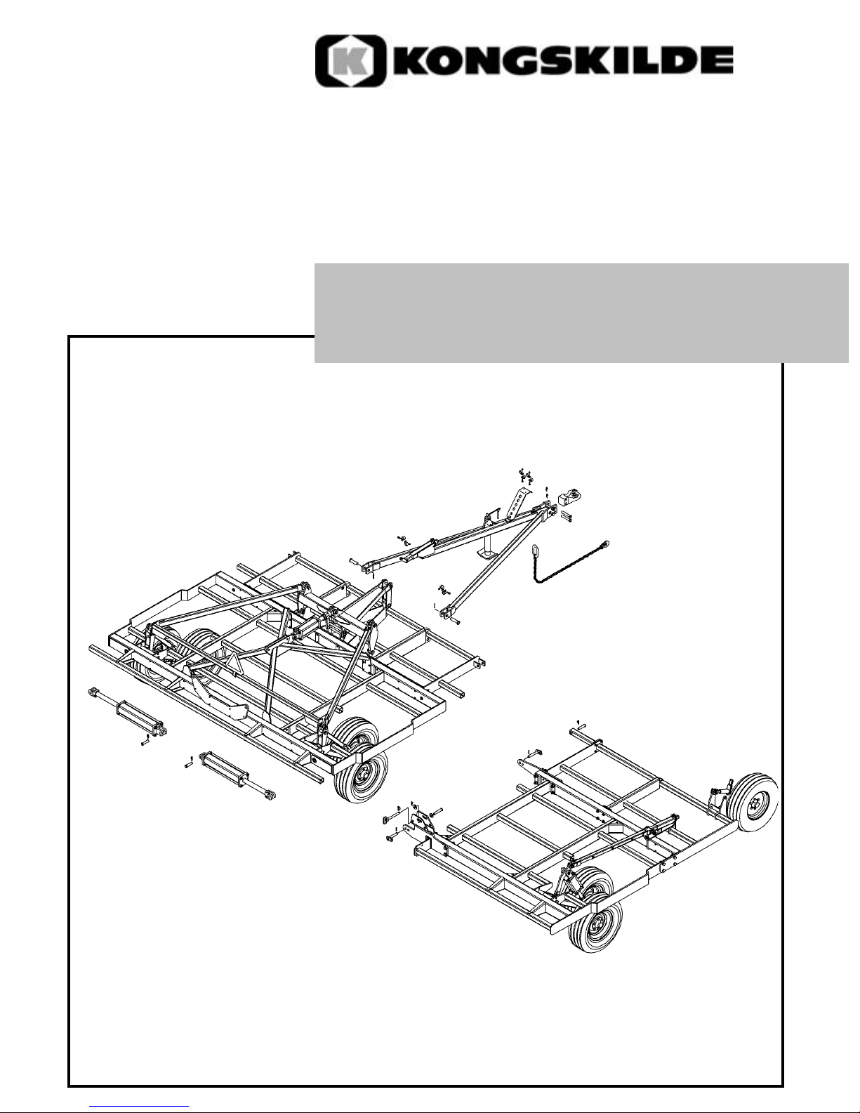
2800 VIBRO-TILL
FIELD CULTIVATOR
Kongskilde
2800 Series
*Model may not be exactly as shown.
Kongskilde reserves the right to make changes to product designs and specifications without notice or obligation to rework.
See your local Kongskilde representative for current product
specifications, instructions and options.
ASSEMBLY INSTRUCTIONS
Page 2

Introduction:
Please take the time to carefully read and review all instruction booklets provided with your
new Kongskilde product.
These instruction booklets have been developed to assist you in assembling, adjusting and
maintaining your new Kongskilde Product. To obtain optimal performance over the lifetime of
the product read and follow these instructions carefully.
A copy of the Spare Parts List has also been provided in order to identify the components
and hardware needed for each step of the assembly and to help you identify and obtain
replacement parts in the future.
When the assembly of the unit is completed, please refer to the Owners Manual before
attempting to adjust or use the product. The Owners Manual will provide you with further
instructions on the proper Field Settings, Adjustments and Maintenance Procedures for Safe
Operation of the unit.
If optional equipment or attachments have been ordered for your unit, please refer to the
instruction booklets provided for proper installation and adjustment of these accessories.
Please take the time to fill out and return the Owners Registration and Warranty Form provided
in the Owners Manual in order to activate the warranty coverage.
2
Page 3

Pre Assembly Instructions:
Assembly of Kongskilde products should only be undertaken by authorized Kongskilde Dealers
or an approved service provider who has the necessary tools, equipment and training for safe
handling and proper assembly of the unit.
Proper handling and assembly of the components is critical in order to validate the warranty
policy.
It is important to note that the frame components are heavy and somewhat awkward to handle.
Proper lifting devices such as overhead cranes, boom lifts or mobile lift trucks should be used
at all times when moving or handling the large frame components and must only be operated
by individuals who have had the proper safety training for using such devices. Proper steel
assembly stands or support jacks should also be used to support the frame components and
prevent them from falling during assembly.
Recommended assembly tools include:
A full set of standard open or box end wrenches and sockets; assorted sizes of pin punches;
a heavy hammer and/or sledge hammer; a pry bar; a large adjustable wrench; and pair of
visegrip or similar type pliers.
Optional tools could include an all purpose jack and a good quality air or electric drive impact
tool with heavy drive sockets.
The assembly area should be should be large enough to allow workers and equipment to
move around freely during assembly of the unit.
For example; to fully assemble a 2800-90 with 29' (9m) working width, a minimum area of
30' x 40' (10m x 12m) with 16' (5m) overhead clearance is required to assemble and fold the
machine.
If the unit is to be assembled and folded indoors, additional clearance may be needed in the
assembly area.
The ceiling height and the size of the building exit door must also be considered in order to
safely fold and move the cultivator outdoor after assembly.
The floor area should be relatively clean and level.
Proper lighting and ventilation should also be provided to allow the work to be carried out in
a safe and efficient manner.
3
Page 4
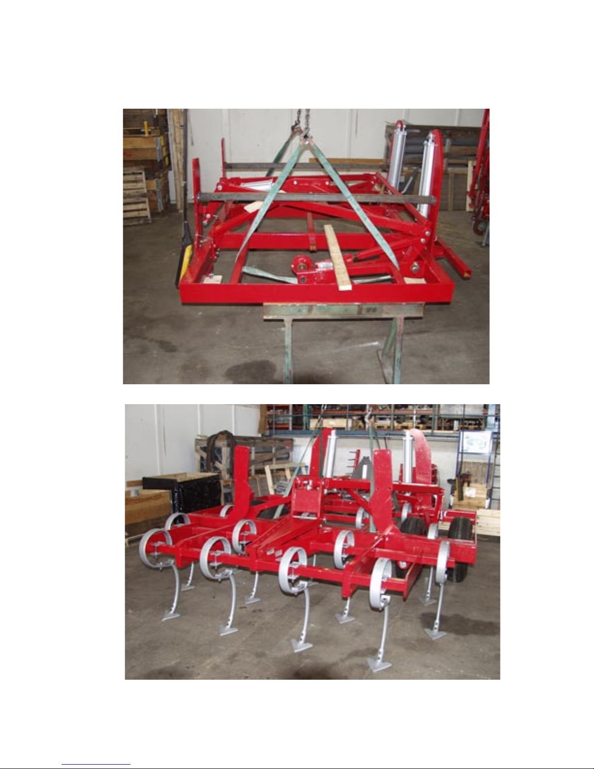
FRAME ASSMEBLY
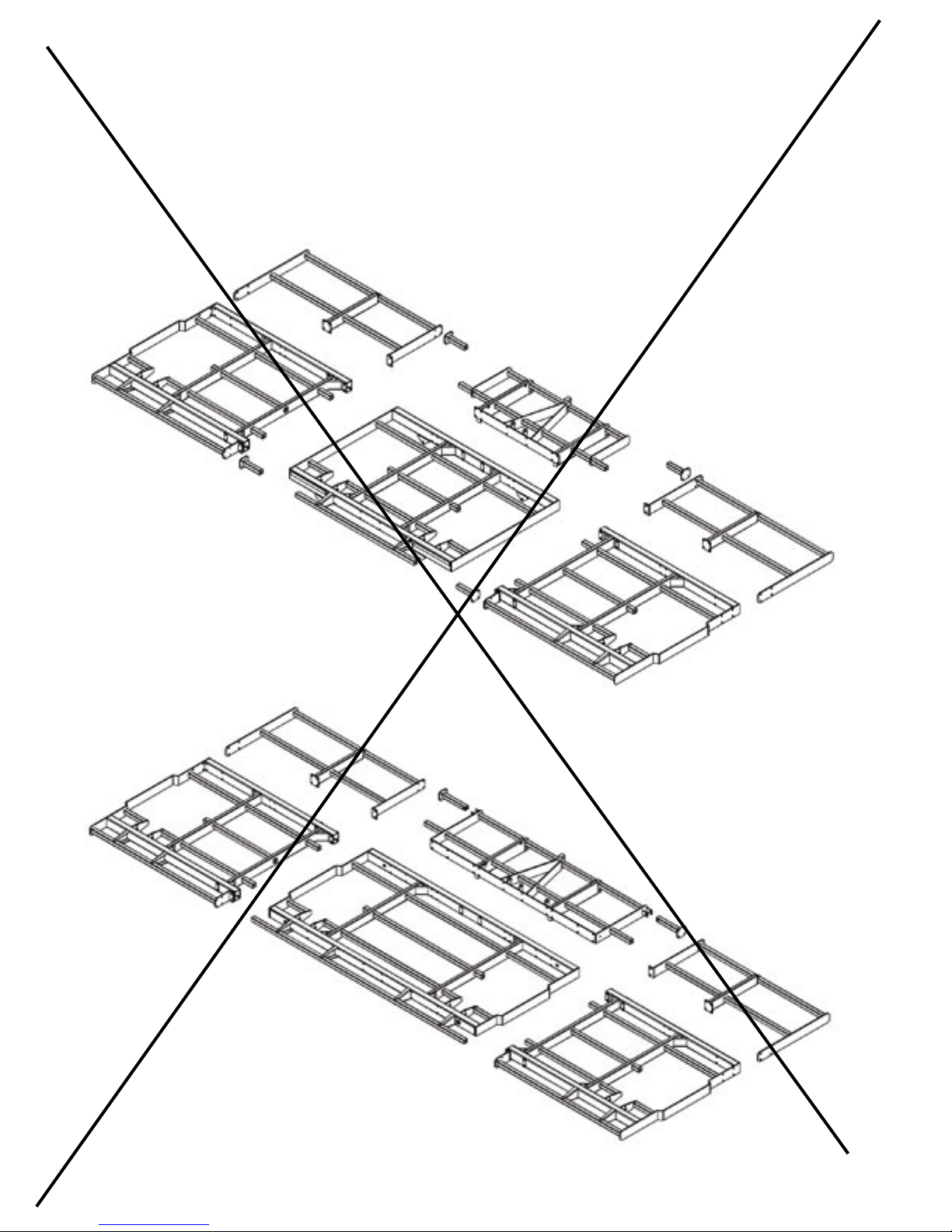
Sort out the frame sections for the size of cultivator you are assembling. Note that there are 2
different centre frame configurations as shown below: 1) 10' (3m) narrow transport model or
2) 13' (4m) wide transport model.
The main wing frames are the same for both the 3m and 4m models however, some compnents
are different such as the folding hinges, assembly hardware and hydraulic hose kits. Refer to
the spare parts list supplied for a full description of all of the different parts for both models.
Frame assembly with
10' (3m) centre section.
Frame assembly with
13' (4m) centre section.
4
Page 5
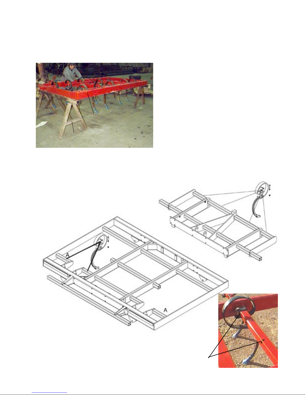
To ensure the stability of the frames and safety of the workers during assembly, place the
cultivator frames on surdy steel shop stands. Do not use construction blocks, tiles or supports
constructed of wood or other materials that could crush under continuous load. Position the
stands so they do not interfere with the mounting of frame components and tines.
Locate the tine patterns in the back of the
booklet for the model of cultivator you ordered
and begin measuring the tine locations on
each of the toolbar tubes.
Note that there are 2 standard tine patterns:
4" (100mm), and 6" (155mm). Tine quantities
delivered with the unit are based on the model
Cultivator frame.
size of cultivator and the tine spacing chosen
at time of order. Therefore, if you decide to
change the tine spacing after delivery of
Steel support stands.
the unit you may need to order extra tines
depending on the pattern you choose. Other
Tines mounted in the wheel area or near the
hinge points should be left loose until after the
tine spacings are available on request for
various special applications.
wheel arm assemblies and wing fold hinge
plates are installed. This will allow the tine to
move out of the way during assembly of the
wheels and hinge components.
Note: On 3m center, a 4 inch
sweep cannot be placed on
toolbar outside the wheel
(position A). Sweep will
interfere with tire.
Hook a tape measure on the "0" side of the cultivator frame and
put a mark on the front side or top of the toolbar tubes at the
dimensions shown on the tine pattern drawings. Mount the tines so
they are centred at the location marked. The mark will be covered
by the clamp and bolt.
5
Page 6
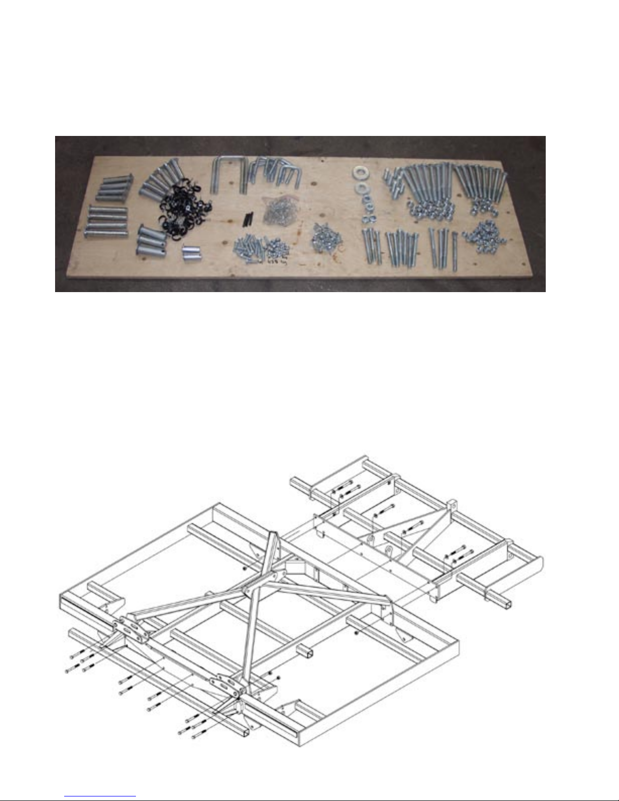
Carefully unpack and lay out all of the fasteners and hardware. (The empty shipping crate
and cardboard makes an excellent temporary work bench.) Assembling the cultivator is more
efficient if you take a few minutes to sort and organize the hardware by type and size instead
of dumping the bag or box in a pile on the floor. Place the assembly instructions and parts list
on the table for quick reference to help identify the parts for each step of the assembly.
When the tines are mounted to the main frame and front extension, move the 2 frame sections
together and assemble the centre section with the bolts, nuts, washers and pins shown in the
parts list.
Take care to insert the front frame bolts from the front and insert the back frame bolts from the
back so that the locknuts are all facing inside the machine. This will keep the frame assembly
looking neat and tidy and make the assembly more efficient.
(Note: The assembly diagrams do not show tines installed for easier viewing. In special
situations where the machine must be partly assembled and shipped to another location, the
tines may be mounted after assembly. But generally you will find it easier to mount the tines
as you assemble each frame section.)
Example:
10' (3m) Centre & Front Frame Assemby
6
Page 7
Frame assembly can be done while the frames are sitting on the assembly stands, or the
stands may be removed once the tines are mounted. Use a fork lift or overhead hoist to move
the heavy frame components into position for assembly.
7
Page 8

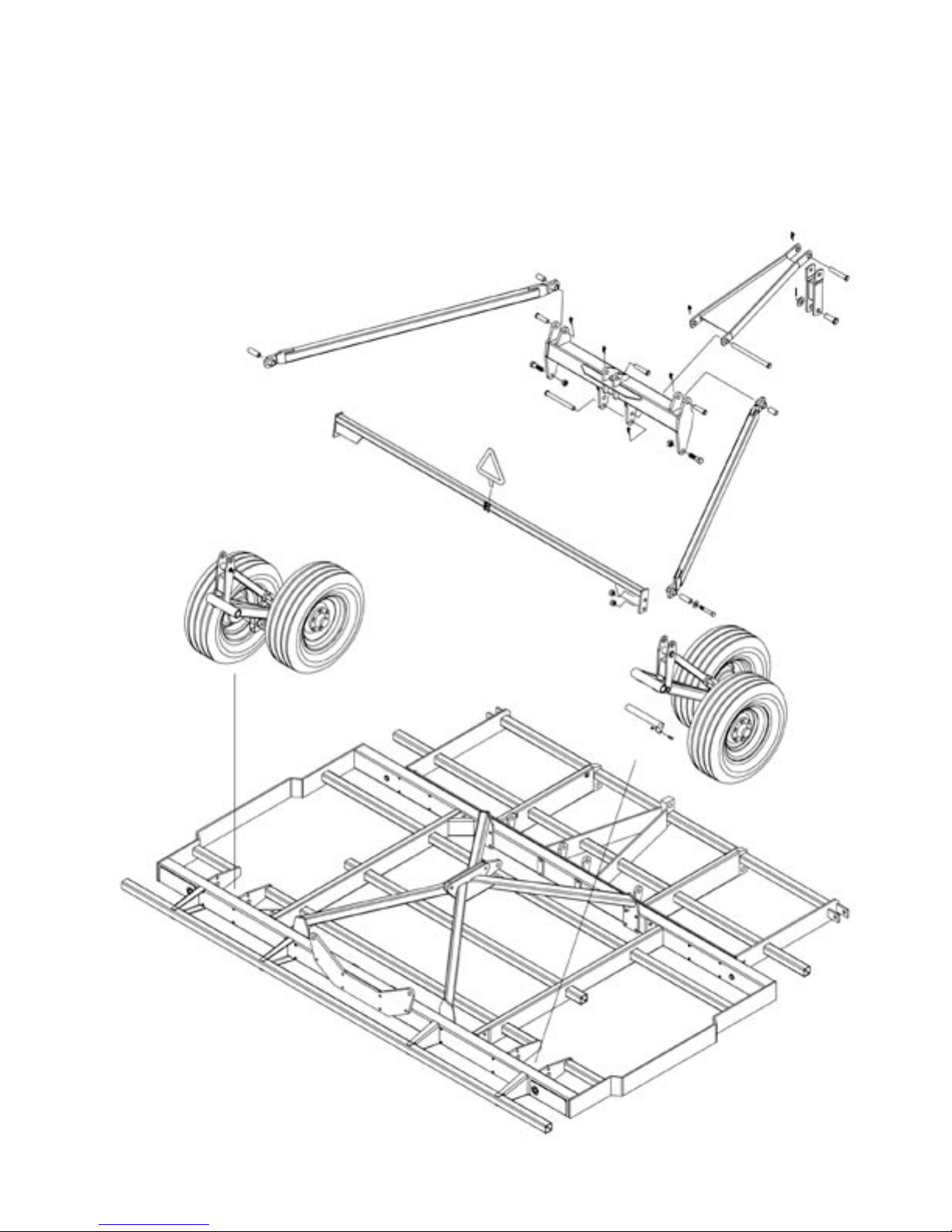
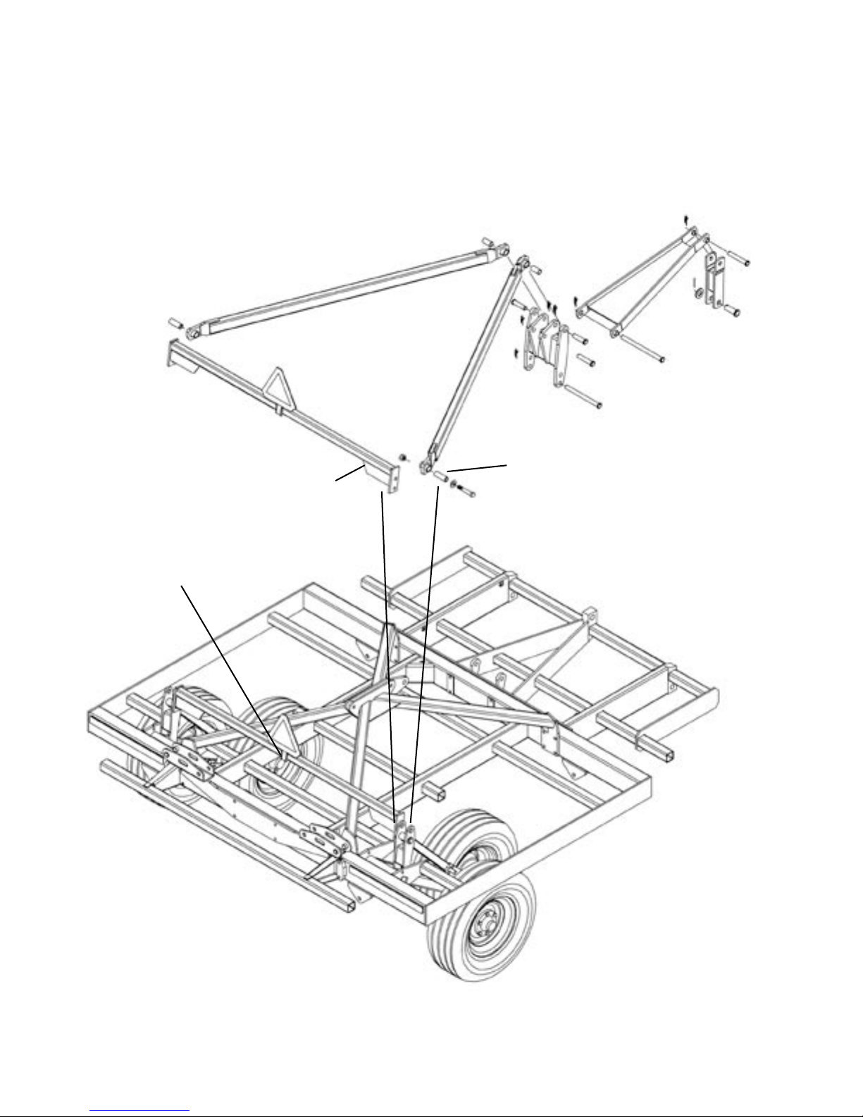
Although the 10' (3M) and 13' (4M) centre sections and self levelling wheel lift linkages have
some different components, they both have the same basic function and use the same order
of assembly as shown by the numbers below and opposite.
Sort out the pieces for the centre section self levelling linkages and wheel arms according to
the parts list and the diagram below for 10' (3m) or opposite on page 9 for the 13' (4m).
Important Note:
It is much easier to pre-assemble the right and left wheel arms according to the instructions
on page 10. The entire wheel assembly can then be lifted into the frame and secured with the
wheel axle.
The remaining steps for installing the linkages are outlined in detail beginning on page 11.
10' (3m) Self Levelling Linkage Assembly
3
1
8
7
6
5
4
2
8
Page 9
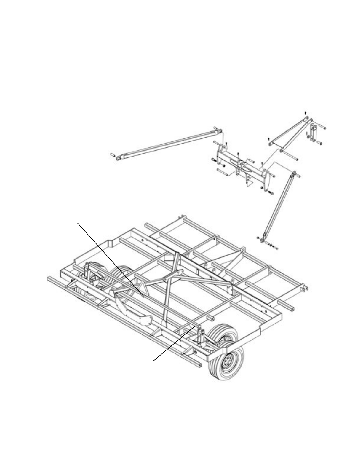
After the wheel arm assemblies are installed, the self levelling linkages can be attached starting
with the wheel connection link at the back and work forward to the hitch. The numbers below
show the proper order of assembly. Refer to the detailed instructions beginning on page 10
for proper assembly of the wheel arms and self levelling lift linkages.
13' (4m) Self Levelling Linkage Assembly
8
7
6
4
5
1
3
2
9
Page 10
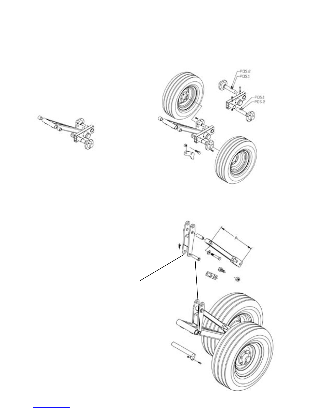
Carefully insert the wheel axle pivot bushings into the ends of the wheel arm tubes. Tap the
bushings into the ends of the tubes with a block of wood or rubberized hammer.
Before mounting the tires, install the wheel spindle bolts as shown. The front spindle must be in
the 1st hole or wide position for all centre machines. The rear spindle must be in the 2nd hole
on the 10' (3m) centre. The rear spindle should be in the 1st hole for the 13' (4m) center.
Never use a steel block or hammer
directly on the bushings as they are
from a material which can crack or
burr easily.
Assemble the wheel linkage as shown below with the pivot pins and bushings provided.
Note that the wheel pivot link shown below is a 2 piece adjustable linkage. This linkage can
be lengthened or shortened as necessary to provide proper under frame clearance for 20" or
24" tine options. This adjustable wheel link also provides side to side levelling for the centre
section.
The linkage length from centre to centre
"Dimension A" should be set at:
A = 28" (71cm) for 20" clearance tines.
A = 28.5" (73cm) for 24" clearance tines.
Take care to install the pins from
the outside as shown with the clip
pins on the inside of the wheel
arm.
10
Page 11
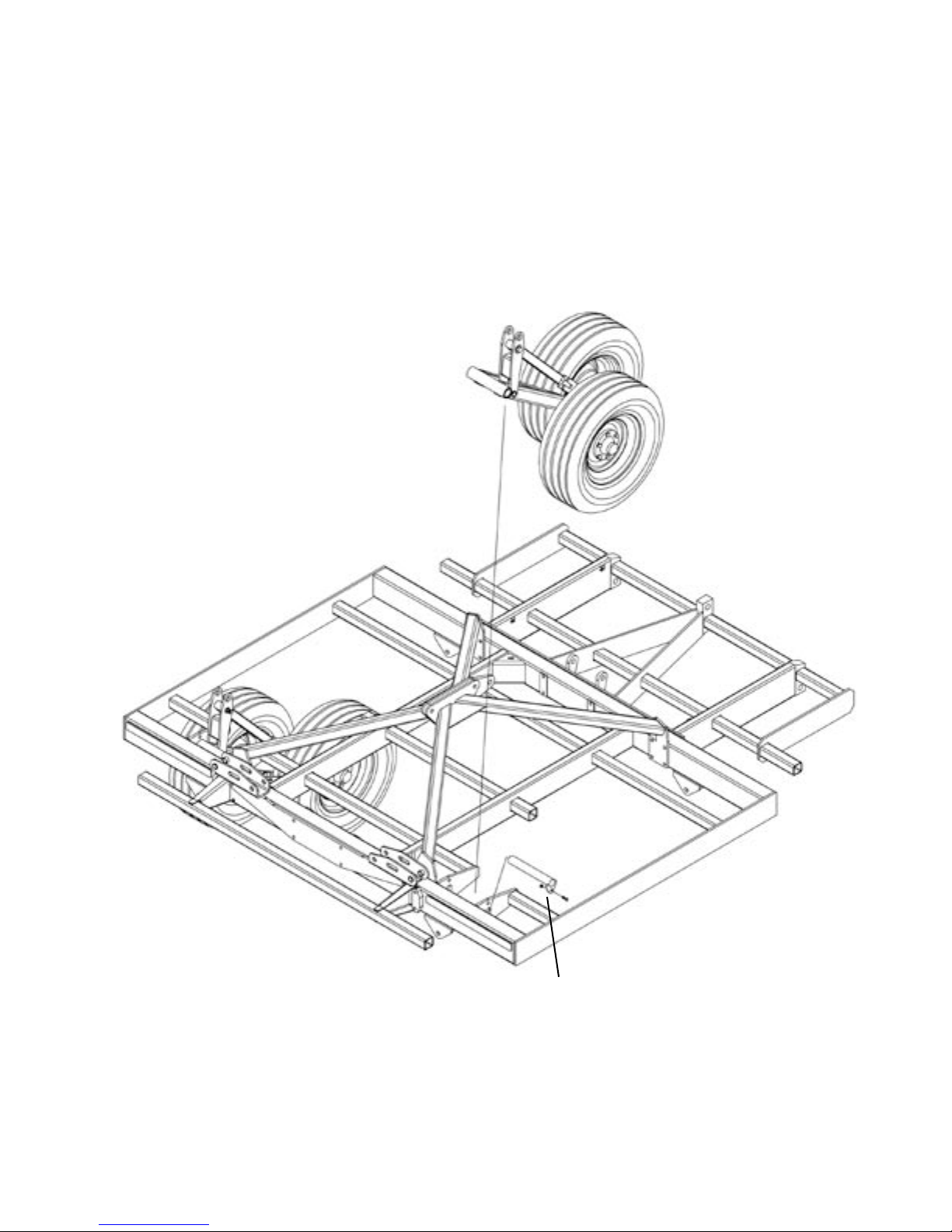
Using a lift truck or overhead hoist equipped with an approved lifting chain or strap, lift the
wheel arm assemblies one at a time into the centre frame as shown below before installing
the Self Levelling Wheel Arm Pivot Linkages.
The wheel arm pivots must be aligned with the holes in the frame and then secured with the
axle pin as shown in the detail below.
The pin can be coated with a light machine oil or grease to ease assembly but otherwise needs
no lubrication as the pivot bushings in the wheel arms are oil impregnated.
Install the axle pin with lock tab
pointing down and secure with the
bolt and locknut. Considerable force
is required to install the axle as the
tolerance is very close.
11
Page 12
For the 10' (3m) centre, attach the short Wheel Link Connector to the Wheel Arm Pivot Links
and A-Frame Wheel Links with the bolts provided. Remember to install the spacer bushings
so the upper pivot point will not bind when the bolts are tightened.
10' (3m) Self levelling
Pivot Links
A-Frame Wheel Links
The Wheel Link Conne ctor is
installed between centre wheels
with bu shings and bolt s wi th
locknuts.
Install the linkage with the SMV sign
bracket to the rear then insert the
SMV sign.
Centre Link Spacer Bushing
Must be installed in A-Frame
wheel Link before installing
bolt.
12
Page 13
For the 13' (4m) centre, the assembly is the same only the Wheel Link Connector is longer.
Attach the Wheel Link Connector to the Wheel Arm Pivot Links and A-Frame Wheel Links
with the bolts provided.
Once again, remember to install the spacer bushings so the upper pivot point will not bind
when the bolts are tightened.
13' (4m) Self levelling
Pivot Links
A-Frame Wheel Links
Install the linkage with the SMV sign
bracket to the rear then insert the
SMV sign.
The Wheel Link Conne ctor is
installed between centre wheels
with bu shings and bolt s wi th
locknuts.
13
Page 14

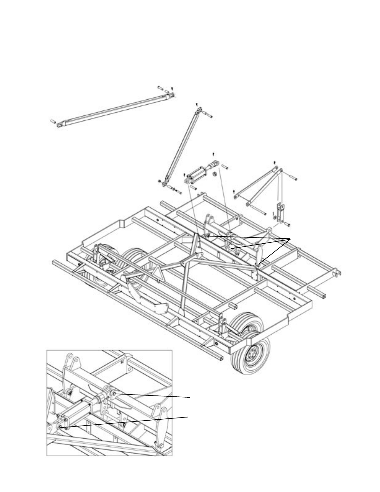
Install the 10' (3m) main pivot link with the long pin provided. When the main link is in place
install the 4.5" x 8" master cylinder as shown in the detail below. Do not install the other linkages
until both the main pivot link and cylinder are in place.
Install Main Pivot Link
and Master Cylinder
Attach the master cylin der with the pins
provided.
The rod clevis attaches to the lugs on the main
pivot link.
The butt end of the cylinder attaches to the lug
in the centre of the top cross frame.
Take care to turn the cylinder so the front or rod
end port is pointing down and the rear port is
facing to the left side.
Remove the protective port plugs so the cylinder
can be moved in or out during the assembly of
the remaining self levelling linkages.
14
Page 15
The 13' (4m) main pivot installs in much the same way as the 10' (3m) except that the 13' main
pivot is larger and requires a central pivot pin and additional mounting bolts to be installed in
the outside pivot mounts. The pivot bolts should not be tightened fully so that the pivot link can
move freely when the cylinder is extended or retracted. When the main link is in place install
the 4.5" x 8" master cylinder as shown in the detail below. Do not install the other linkages
until both the main pivot link and cylinder are in place.
Install Main Pivot Link
and Master Cylinder
Bolts and Pin
for 13' (4m)
Main Pivot Link
Attach the master cylin der with the pins
provided.
The rod clevis attaches to the lugs on the main
pivot link.
The butt end of the cylinder attaches to the lug
in the centre of the top cross frame.
Turn the cylinder so the front or rod end port is
pointing down and the rear port is facing to the
left side.
Remove the protective port plugs.
15
Page 16
Install the A-frame wheel links on the 10' (3m) centre as shown below. The wheel links are
identical so it does not matter which way you turn them.
Attach the front of the wheel linkages to the main pivot with the 1" (25mm) ID bushings and
insert the pins from the outside to secure both linkages to the main pivot link. It may be
necessary to extend or retract the cylinder rod by hand in order to line up the holes and install
the linkage pins. Take care to insert and lock the clip pins when finished.
Attach the rear of the wheel linkage to the upper hole of the wheel
pivot link with the 3/4" (20mm) ID bushing and secure with the
bolts, washers and locknuts provided.
16
Page 17
The A-Frame wheel links are the same for both the 10' and 13' centres, and are installed the
same way as shown below. The only difference is that the links are spaced wider apart on the
13' centre due to the wider frame and wheel spacing.
Attach the front of the wheel linkages to the main pivot with the 1" (25mm) ID bushings and
insert the pins from the outside to secure both linkages to the main pivot link. It may be
necessary to extend or retract the cylinder rod by hand in order to line up the holes and install
the linkage pins. Take care to insert and lock the clip pins when finished.
Attach the rear of the wheel linkage to the upper hole of the wheel
pivot link with the 3/4" (20mm) ID bushing and secure with the
bolts, washers and locknuts provided.
17
Page 18
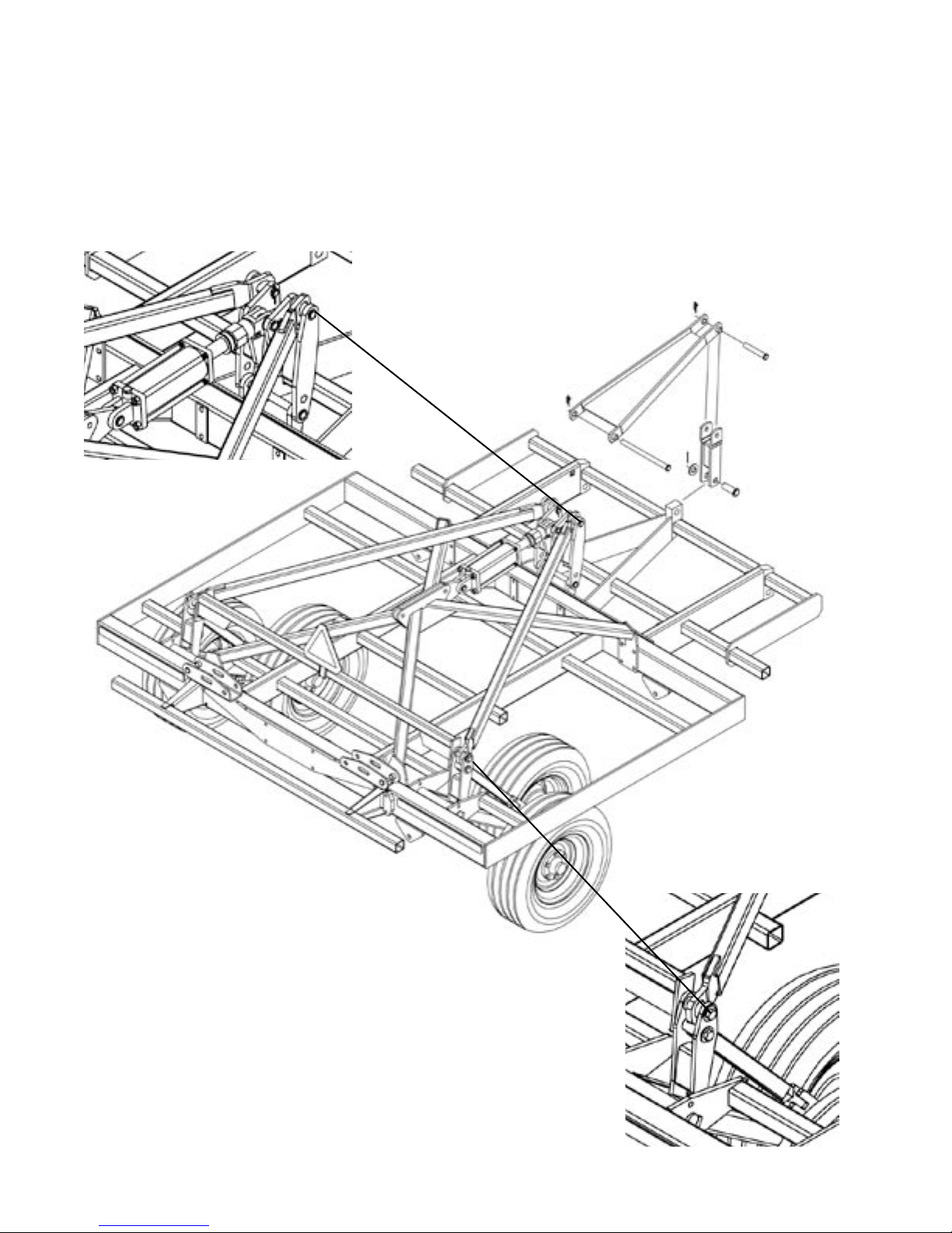
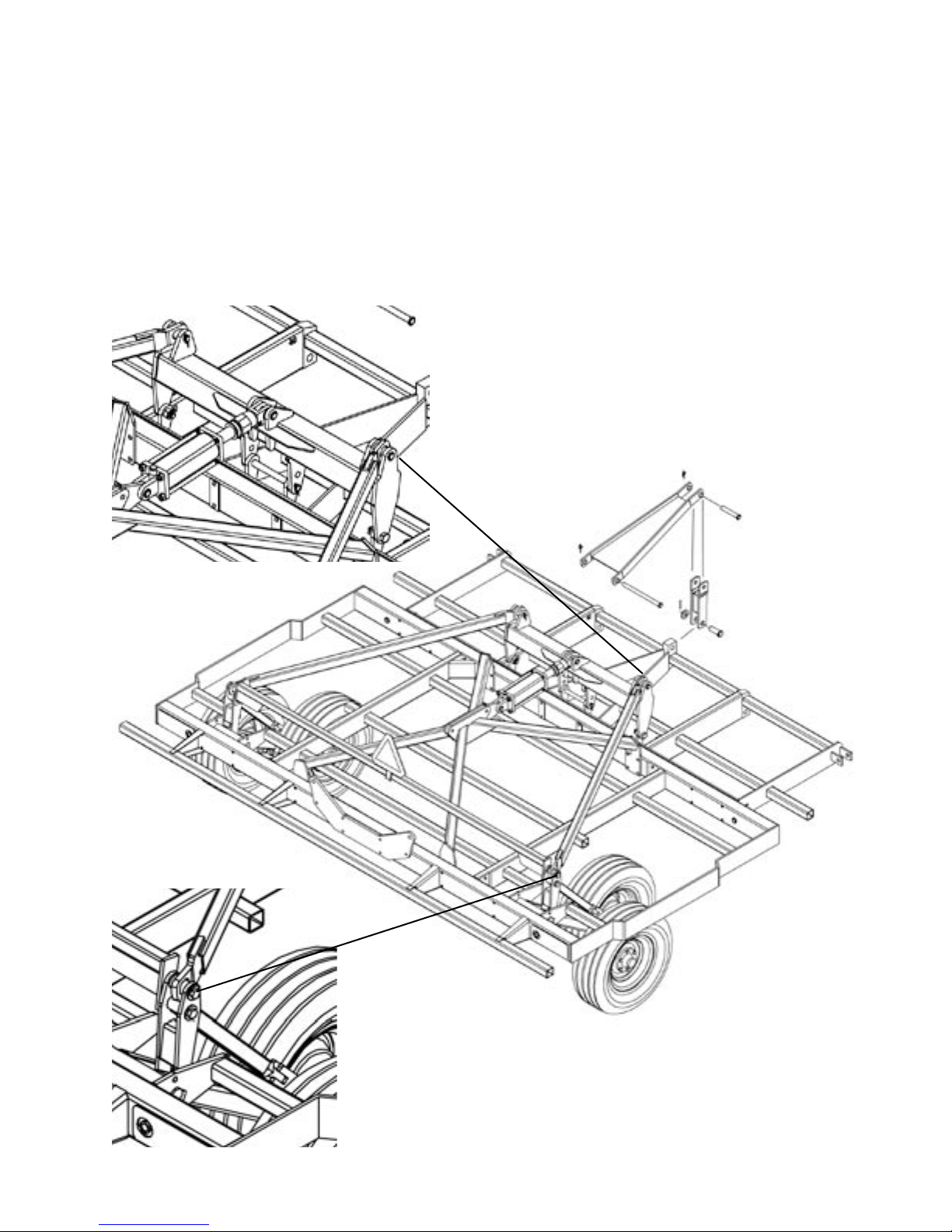
To complete the assembly of the self levelling wheel link system, install the front pivot link to
the lug in the centre of the front frame. Attach the wide end of the large triangular self levelling
link to the main pivot with the long pin provided and attach the narrow end to the front pivot
link with the shorter pin provided. These pieces are the same for both the 10' and 13' centres
and are installed in the same manner.
Check the assembly of the self levelling linkages and make sure all of the clip pins are installed
and locked.
Detail view of front linkages
on 10' (3m) centre
Self levelling link
Front hitch
pivot link
Overview of completed 10'
(3m) self levelling linkage
system.
18
Page 19
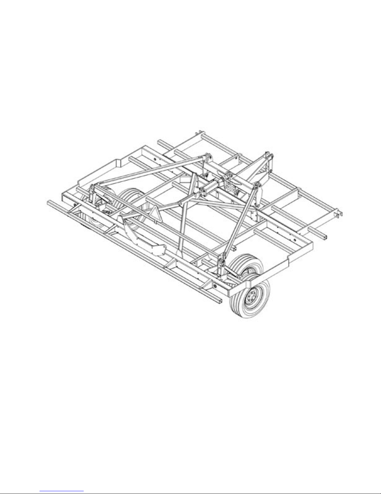
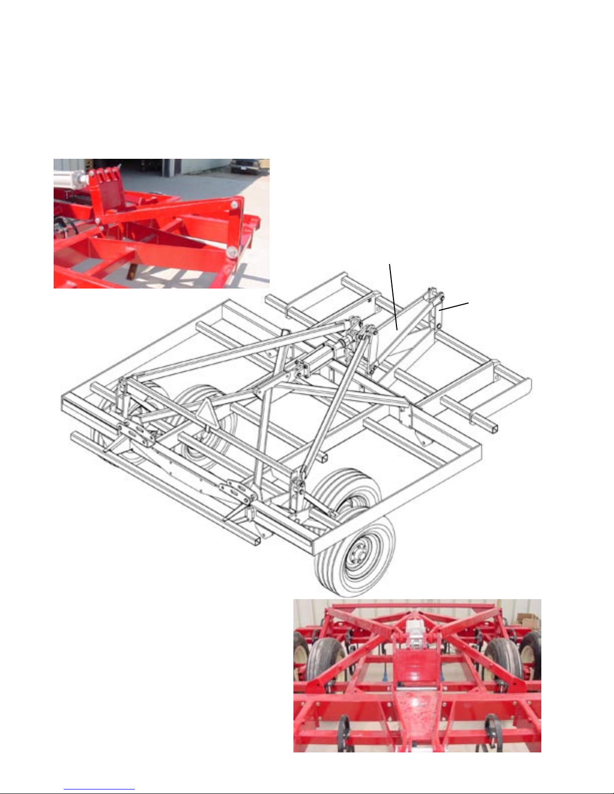
The diagram below shows the completed 13' (4m) centre frame and self levelling wheel lift
linkage assembly.
Take care to go over the assembly of the centre section and linkage system to make sure that
all nuts and bolts are installed and tighened.
Check all pin connections and make sure the roll pins or clip pins are installed and locked.
If there is lots of room in the assembly area, the hitch can be assembled to the centre section
now. However if space is limited, the draw hitch can be assembled and attached later after
the wings are assembled and attached.
The hitch must be attached prior to installing the hydraulic lines and preparing the cultivator
to be raised and folded for transport.
19
Page 20
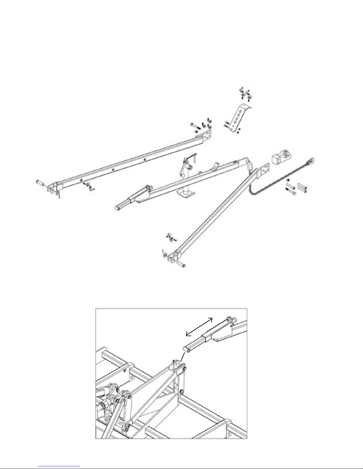
HITCH ASSEMBLY
The draw hitch components are identical for both the 10' and 13' centre sections and follow
the same order of assembly as shown on the numbered diagram below.
Gather the components and begin assembling the hitch with the hardware described in the
spare parts list.
Follow the numbers for the order of assembly on the diagram below and make the connections
with the pins and bolts provided.
4
5
3
1
2
The hitch adjuster, pivot link and self levelling link are all connected with the same pivot pin at
position 1 as shown below. To do this you will have to remove the clip pin and slide the pin to one
side to allow the hitch adjuster to be connected.The adjuster can be lengthened or shortened
as necessary to position the hitch at the tractor drawbar height for easier assembly.
1
20
Page 21

After connecting the hitch adjuster at position 1, attach the hitch side members with the 1-1/2"
pins with washers and roll pins at position 2 and 3. The side tubes are both the same and can
be flipped either way to make the left and right side member.
3
1
2
As shown in step 4 below, place the large eye of the saftey chain over the bushing at the front.
connect the hitch tubes togeather by inserting the the 2 long bolts from opposite sides and
tightening the locknuts. The hitch adjuster link and clevis casting are secured in place with the
long pins and clip pins. Install the jack and hose tower as shown in step 5.
The hook end of the saftey chain is for connecting the chain to the tractor hitch.
4
5
21
Page 22

WING ASSEMBLY
Gather the components for the wing frames and assemble using the hardware described in
the parts list booklet. The wing frame sections are basically the same for both 10' (3m) - shown
below, and 13'(4m) centre machine - shown opposite. The main difference between the wing
assembly of these 2 models is in the folding hinges and stub toolbars.
Note how the wing fold hinges for the 10' (3m) model below are different from the ones shown
on the opposite page, and how the model below has front and rear stub toolbars.
Please note that there are no right or left wing frame components. Therefore if you assemble
the right wing first as shown below, you will need to flip the frames over opposite to the diagram
below to assemble the left wing.
Mark the tine pattern on the wing frame tubes according to the locations given for each wing
frame section in the back of the book by hooking the tape measure on the side marked "0"
and measuring across the frame as you did for the centre section.
The frames should be placed on steel support stands during assembly and mounting of the
tines, then carefully lowered to the ground to rest on the tines for assembly of the wheel
components.
Note: Front and Rear
Bolt-on Stub Toolbars
Example:
Wing Assembly with 10' (3m)
Narrow Fold Hinges
Tines mounted near the hinge plates or in the wheel area
should be left loose until after the wheel arm assemblies
and hinge plates are installed to allow better access to the
mounting bolts with tools.
22
Page 23

The assembly diagram below shows the different folding hinges and front bolt on stub toolbar
used on the cultivator model with 13' (4m) centre section.
Also, Note how the front stub toolbar has a hinge pin that connects to the 13' centre front
frame and there is no rear stub toolbar on this model.
Refer to the parts list provided for complete discription of the components and hardware for
proper assembly of the wings.
The assembly diagrams do not show tines installed on the frames for easier viewing of the
components. You may choose to assemble the frames first and mount tines later, but generally
you will find it is easier to mount the tines as you assemble the frame sections.
Note: Front Bolt-on Stub
Example:
Toolbar with Hinge Pin
Wing Assembly with 13' (4m)
Wide Fold Hinges
Tines mounted near the hinge plates or in the wheel area
should be left loose until after the wheel arm assemblies
and hinge plates are installed to allow better access to the
mounting bolts with tools.
23
Page 24

Install the front and rear folding hinges to the frames at the same time as you assemble the
wing frames. The hinge pins and fold cylinder pins are installed later when connecting the wings
to the centre section. Take care to leave the nuts and bolts loose at the hinges as it makes it
easier to align the holes when attaching the wings to the centre section.
Stub Toolbar
Front folding hinge 10' (3m)
Front extension frame
Rear folding hinge 10' (3m)
Stub Toolbar
Front folding hinge 13' (4m)
Rear folding hinge 13' (4m)
Wing main frame
Stub Toolbar with
Hinge Pin
Front extension frame
Wing main frame
24
Page 25

When the wing frame is fully assembled and lowered to the ground resting on the tines, gather
the components for the wing tandem wheel and wheel adjustment linkages.
Before mounting the wheels on the hubs, install
the wheel spindle bolts as shown. The front
spindle must be in the wide position 1. The rear
spindle should be in the wide position 1.
Install the pivot bushings
into the ends of the wheel
arm tubes. Do not hammer
directly on the bushings,
tap them in using a wooden
block or rubber mallet.
Mount the wheels on the hubs and then lift the complete tandem wheel assembly into the wing
frame. Apply a little grease or machine oil to the axle pin to ease assembly and then insert
the pin through the holes in the wing frame and wheel arm.
Make sure the pin lock tab is pointing down before installing the lock nut and bolt.
Note it takes considerable force to install the axle pin as
the tolerance is very close.
The axle does not require any lubrication after assembly as
the wheel arm pivot bushings are oil impregnated.
Tab points down
25
Page 26

Mount the wing wheel tower and wheel lift cylinder with the pins, bolts and nuts described in
the parts list. The wheel cylinder upright attaches to the upper hole in the wheelarm tube with
the pin and clip pin supplied.
Note that the wing wheel lift cylinders are different sizes. One is 4.25 x 8 the other is 4 x 8.
Check the hydraulic layout in order to make sure you install the cylinders on the correct side
of the machine. The 4.25 x 8 cylinder is installed on the left wing and the 4 x 8 cylinder is
installed on the right wing as shown below. The ports on both cylinders should face into the
centre of the machine.
The butt end or top of the cylinder is connected to the wheel upright bar with one of the pins
and clip pins supplied. The rod end clevis connects to the lug on the lower end of the wheel
arm so the cylinder extends and retracts with the rod pointing down. The clevis pin is special
and has a mounting plate with bolt and locknut to secure it in place.
Wheel Cylinder Upright
NOTE: The lower cylinder pin
is special for this location and
is held in place with a bolt and
locknut.
4 x 8 Cylinder on Right Wing
- Cylinder Ports face inside
to Centre
26
Page 27

Install the wing wheel adjustment linkage with the pins, locking clip pins and U-bolts
supplied.
The wheel linkage tube should be mounted with the hose brackets on the inside as shown in
the detail photo below.
Take care to keep the linkages straight when tightening the U-Bolts so the adjustment slider
does not bind when adjusted in and out.
Note: Flip Linkage Tube
over so hose clips face
inside to centre.
27
Page 28

The adjustment linkage is used to adjust the wings so they are level with the centre section
when working in the field.
To adjust the linkage, remove the clip pin and turn the adjustment casting clockwise or counter
clockwise to lengthen or shorten the linkage. This in turn will raise or lower the wing wheel arm
position so the wings will run level at the same depth as the centre section. The adjustment
can be made with either a large adjustable wrench, or 1-1/2" socket, or a 3/4" drive socket
wrench handle only.
More information on the proper adjustment of these linkages is covered in the Owners Manual
under Field Settings and Adjustments.
Initially the adjustment slider can be set at 7' - 8" or (180 to 205mm). The distance is measured
from the edge of the outer housing tube to the centre of the pin.
Take care to replace the clip lock pin so the slider adjustment does not move from the set
position.
7" - 8"
(180 - 205mm)
28
Page 29

Mechanical Adjust Wheels on 3'3" (1.0m) Wings:
The mechanical adjusting wheel is used as the wing depth wheel on the 16' (5m) model
cultivator with 1m wings. It is also available as an accessory wing gauge wheel on all other
models.
On the small 3'3" (1.0m) Wing, the wheel is mounted inside the wing frame to the toolbar as
shown below. It should be assembled with the wheel mounted to the outside and positioned
to run about 1-1/2 to 2" away from the outside of the wing.
The mounting bracket and wheel arm are designed to allow the wheel to be assembled for
right or left hand use by turning the wheel arm over and mounting the turnbuckle adjuster on
the opposite side of the mounting bracket. The diagram below shows the wheel assembled
for the right side wing.
Adjustment of the working depth of the wing is accomplished using the mechanical ratchet
on the turnbuckle. An extension handle is provided for easier adjustment of the mechanical
ratchet.
29
Page 30

Mechanical Adjust Wheel used as Front Gauge Wheel:
When used as a front gauge wheel the gauge wheel mounting bracket is attached to the
front toolbar with the U-bolts provided. Again, the tire is usually mounted to the outside and
positioned near the front corner of the machine. The exact position will vary depending on the
tine pattern but the wheel should not stick out past the outside of the wing.
The mounting bracket and wheelarm are designed to allow the wheel to be assembled for
right or left hand use by turning the wheel arm over and mounting the turnbuckle adjuster on
the opposite side of the mounting bracket. The diagram below shows the wheel assembled
for the right side wing.
Adjustment of the gauge wheel is accomplished using the mechanical ratchet on the turnbuckle.
An extension handle is provided for easier adjustment of the mechanical ratchet.
Instructions for adjusting wheels and setting the working depth is explained in detail in the
Cultivator Owners Manual. When working in the field, the gauge wheels should only have light
contact with the ground in order to hold the depth accuracy of the wing and prevent it from
bouncing.
As a preliminary setting the wheels can be adjusted about 2" from the ground when the
cultivator is resting on the tines.
30
Page 31

Final Assembly of the 10' (3m) Centre Section and Wings:
Move the wing assemblies into position beside the centre section.
Install the wing hinge pins according to step 1 & 2 in the diagram below. The hinge plate bolts
should be loose to allow easier alignment and insertion of the hinge pins.
The main hinge pins are designed to lock in position and must be turned so that when they
are inserted thru the hinge plates and centre frame, the pin stub locks into the second hole
in the hinge plate before the roll pin can be installed.
When the pins are installed tighten the hinge plate bolts
1
2
31
Page 32

Folding Cylinders for 10' (3m) Centres:
When the wings are attached to the centre section the wing fold cylinders with hydraulic hose
lines and fittings can be installed.
The hydraulic assemblies are different for the 10' (3M) and 13' (4m) centre machines so make
sure you have the correct diagram for the machine model you are assembling.
The most noticeable difference is that the machines with 10' (3m) centres have a different
wing fold system to keep the machine as narrow as possible in road transport.
The wing fold hinge pivots are lower and the folding cylinders are installed to extend and retract
in reverse with cylinder rods pointing towards each other. The butt clevis are attached to the
folding hinge plates on the wings and the rod clevis are attached to slots in the centre section
fold bracket. (The slots allow the wings to float up and down in the field when the cylinders
are fully extended.)
Install the wings and fold cylinders as shown on the assembly diagram below and follow the
Hydraulic Hose layouts carefully for proper assembly of the hoses and fittings shown later in
this booklet.
32
Page 33

Detail Pictures of the 10' (3m) Fold Cylinders Installed:
Be sure to place four (4) 1" washers
at rod end of cylinder. The inside
two (2) keep the clevis centered.
Shown: Cylinders in extended
position. Fold lock pin goes in
storage hole when not being used.
Cylinders in folded position.
Insert fold lock pin as shown.
33
Page 34

Final Assembly of the 13' (4m) Centre Section and Wings:
Move the wing assemblies into position beside the centre section.
Install the wing hinge pins according to step 1, 2 & 3 in the diagram below. The hinge plate
bolts should be loose to allow easier alignment and insertion of the hinge pins. The main hinge
pins are designed to lock in position and must be turned so that when they are inserted thru
the hinge plates and centre frame, the pin stub locks into the second hole in the hinge plate
before the roll pin can be installed.
The front toolbar stub also acts as a 3rd hinge to provide greater stability for the front frame
extension on the wide fold models. Secure the front toolbar hinge pins in place with the locking
clip pin. When the pins are installed re-tighten the hinge plate bolts
Detail view of front frame
hinge pin with locking clip
pin installed.
1
13' (4M) Wing Fold
Lock Brackets
2
3
The 13' (4m) centre also has special wing lock brackets that must be installed before folding
the wings. The brackets are installed on the main frame tube behind the wheel arm. Mount
the lock brackets with the bolts provided but do not tighten the locknut. You will need to move
the brackets in order to allign the hole in the bushing with the hole in the wing hinge plates in
order to insert the wing fold lock pin.
Refer to the pages for the hydraulic assembly for further instructions.
34
Page 35

Folding Cylinders 13' (4m) Centres:
When the wings are attached to the centre section the wing fold cylinders with hydraulic hose
lines and fittings can be installed.
The hydraulic assembly is different for the 13' (4m) centre machines so make sure you have
the correct hose layout diagram for the machine model you are assembling.
The most noticeable difference is that the models with 13' (4m) centres have additional fold lock
brackets that must be installed in order to lock the wings in the folded position for transport.
The other difference is that the folding cylinders are installed so the cylinder rods extend and
retract pointing away from the centre. The cylinder butt clevis are attached to the centre fold
plate and the rod clevis are attached to the slot in the folding hinge brackets on the wings. (This
allows the wing to float up and down in the field when the cylinders are fully extended.)
Install the rear folding brackets and cylinders as shown on the assembly diagram below and
follow the Hydraulic Hose layouts carefully for proper assembly of the hoses and fittings shown
later in this booklet.
35
Page 36

Detail Pictures of the 13' (4m) Fold Cylinders Installed:
Cylinders in extended Position. Place fold lock pin in storage
hole when not being used.
With cylinders in folded position,
adjust fold lock plate so that the
fold locking holes lineup.
Insert fold lock pin as shown.
36
Page 37

Hydraulic Diagrams and Assembly Information:
For proper installation of the hose lines and fittings refer to the hose layout diagram provided
later in the booklet. The hydraulic hose lines and fittings are provided in the hose kit. Secure
the hoses to the frames with the hose clamps, carriage bolts and locknuts provided.
IMPORTANT NOTE:
DO NOT PLACE HOSE LINES ALONG FRAME IN FRONT OF TOP FRAME MOUNTING
PLATES AS SHOWN BELOW.
HOSE LINES CAN BECOME PINCHED BY THE FRONT WING FOLD STOP PLATE WHEN
FOLDING IF HOSES ARE LAYING ON TOP OF THE FRAME TUBE.
HOSES SHOULD BE BEHIND THE TOP
FRAME AND NEATLY CLAMPED SO
THEY DO NOT INTERFERE WITH THE
HINGES WHEN FOLDING.
KEEP HO S E S L I NES RUNNING
ACROSS THE CULTIVATOR BEHIND
THE FRAME TUBE AND NEATLY
CLAMPED TO THE FRAMES WITH
THE HOSE CLAMPS OR PLASTIC
TIE STRAPS PROVIDED.
37
Page 38

NOTE: On a 3m Center machine, fasten the
hoses to the wing frame and feed the cylinders
from there. Also, tie hoses to the rod port as
shown above
NOTE: On a 3m Center machine, route
the fold hoses in front of top frame leg
Charge the wheel lift hydraulics by fully
extending and retracting the wheel lift
hydraulic cylinders several times. Hold the
hydraulic lever open at the end of the stroke
to purge the air from the system.
The wheel lift cylinders are rephasing type
cylinders and must be fully extended at the
end of the field when turning to equalize the
oil pressure across the system.
This will ensure that the cultivator raises and
lowers evenly and stays at a uniform working
depth when working in the field.
38
Page 39

The wing fold cylinders must be charged with
oil before attempting to fold the cultivator.
Disconnect the cylinder rod clevis from the
fold bracket and place a block under the
cylinders as shown.
Connect the hoses to the tractor or portable
hydraulic unit and stroke the wing fold
cylinders in and out several times holding the
lever at the end of the stroke to remove the
air from the system and ensure the cylinders
and hoses are full of oil. Remove the block and
reconnect the cylinder to the fold bracket with
the cylinder pin, washer and clip pin.
Always insert the transport lock on the master
cylinder when ever the cultivator is placed in
the raised position for transport, maintenance
or stroage.
Secure with the lock pin and clip provided.
Always insert the wing fold lock pins and
secure the lynch pin when ever the wings
are raised in the folded position. Be sure to
remove the pins and store them in the storage
holes before unfolding the cultivator.
Never transport the cultivator on public road
ways without installing the transport safety
chain and SMV sign.
See the special instruction sheet for proper
placement of the cultivator identification
decals and safety warning decals
Refer to the Owners Manual for further
safety information before attempting to
operate or service the unit
39
Page 40

40
Page 41

Spare part list / 2800 Hydraulics. Date: 2003, 02.
Fig. Part no. Description
1 600470233 1/2" Hose 1/2" Pipe x 1/2" JIC - 240" all models (2 req'd on non fold models)
2 600470244 1/2" Hose 1/2" Pipe x 1/2" JIC - 397" (2800-6m-20')
600470235 1/2" Hose 1/2" Pipe x 1/2" JIC - 417" (2800-7m-23')
600470245 1/2" Hose 1/2" Pipe x 1/2" JIC - 437" (2800-8m-26')
600470234 1/2" Hose 1/2" Pipe x 1/2" JIC - 457" (2800-9m-30')
600470269 1/2" Hose 1/2" Pipe x 1/2" JIC - 477" (2800-10m-33')
3 600470182 1/2" Hose 1/2" JIC x 1/2" JIC - 175" (2800-6m-20')
600470239 1/2" Hose 1/2" JIC x 1/2" JIC - 195" (2800-7m-23')
600470177 1/2" Hose 1/2" JIC x 1/2" JIC - 215" (2800-8m-26')
600470137 1/2" Hose 1/2" JIC x 1/2" JIC - 235" (2800-9m-30')
600470272 1/2" Hose 1/2" JIC x 1/2" JIC - 255" (2800-10m-33')
4 600470147 1/2" Hose 1/2" JIC x 1/2" JIC - 310" (2800-6m-20')
600470149 1/2" Hose 1/2" JIC x 1/2" JIC - 350" (2800-7m-23')
600470151 1/2" Hose 1/2" JIC x 1/2" JIC - 390" (2800-8m-26')
600470153 1/2" Hose 1/2" JIC x 1/2" JIC - 430" (2800-9m-30')
600470273 1/2" Hose 1/2" JIC x 1/2" JIC - 470" (2800-10m-33')
5 600470049 Elbow 1/2" O-ring x 1/2" JIC - 90 Degree
6 600470232 3/8" Hose 1/2" Pipe x 3/8" JIC - 280" (All Folding Models)
7 600470270 3/8" Hose 3/8" JIC x 3/8" JIC - 62" (All narrow centre models -3m)
8 600470297 3/8" Hose 3/8" JIC x 3/8" JIC - 82 “ (All narrow centre models -3m)
9 600470003 Tee 3/8" JIC (All narrow centre models -3m)
9A 600470295 Tee 3/8" JIC x 3/8" JIC x 1/2" ORB (All wide centre models -4m)
9B 600470296 Tee 3/8" JIC x 3/8" JIC(FS) x 3/8" JIC (All wide centre models -4m)
10 600470124 Elbow 1/2" O-ring x 3/8 JIC
11 600470290 3/8" Hose 3/8" JIC x 3/8" JIC -102 “ (All narrow centre models -3m)
11A 600470294 3/8" Hose 3/8" JIC x 3/8" JIC - 100" (All wide centre models -4m)
12 600470289 3/8" Hose 3/8" JIC x 3/8" JIC -126 “ (All narrow centre models -3m)
12A 600470293 3/8" Hose 3/8" JIC x 3/8" JIC - 56" (All wide centre models -4m)
13 600474502 Cylinder 4.5 x 8 Rephasing with Mechanical Stroke Control - Midway
14 600474503 Cylinder 4.25 x 8 Rephasing - Midway
15 600474504 Cylinder 4 x 8 Rephasing - Midway
16 600474557 Cylinder 4 x 24 - Midway
17 600474513 Stop Collar 1"
18 606001331 Cylinder Transport Lock
19 601140780 Pin
20 600333011 Hair Pin Clip
21 600470007 Hose Clamp 3/8"
22 600470047 Hose Clamp 1/2"
23 Carriage Bolt 1/4" x 1"
24 Locknut 1/4"
41
Page 42

When the cultivator frame is fully assembled check all nuts and bolts and secure if loose.
Double check the hose layout and hydraulic connections according to the hydraulic
diagram.
Be sure to read the Owners Manual before attempting to fold or operate the cultivator. The
Owners Manual provides important instructions and safety precautions that must be followed
before attempting to hook up and move the cultivator after assembly.
If you have purchased optional levelling attachments such as the combi harrows shown on the
cultivator below, refer to the Manual provided with the Harrow Assembly for proper installation
and adjustment of the attachments.
*Model may not be exactly as shown.
Kongskilde reserves the right to make changes to product designs and specifications without notice or obligation to rework.
See your local Kongskilde representative for current product
specifications, instructions and options.
42
Page 43

Installing Safety Decals and Product Identification:
1) Install th e Kon gskilde Logo deca ls
#600475113 and Vibro-Till 2800 decals
#600475168 on both sides of the draw tongue
and wing frames as shown.
KONGSKILDE & Vibro-Till
2800 on both sides of hitch
KONGSKILDE & Vibro-Till
2800 on both side of wing
frames
2) Install a Kongskilde Decal #600475113
on both sides of the centre frame side bar
as shown below.
43
Page 44

3) Install Yellow Safety Reflectors #600475131 on both front corners and sides of the 2800
centre section.
YELLOW REFLECTORS
on both front corners and
side bars of front frame.
YELLOW REFLECTOR
front view
YELLOW REFLECTORS
side view
44
Page 45

4) Install Red Safety Reflectors #600475132 on bothrear fold brackets and sides of the 2800
centre section.
RED REFLECTORS on
Rear Hinges and side bar
If the rear reflector position could be blocked from view by harrow mounting brackets then
the reflector can be place in an alternate position on the rear corner of the toolbar to provide
better visibility.
RED REFLECTORS on
Rear Toolbar Tube and Side Bar
45
Page 46

5) The 3 safety decals #600475170, 600475169 & 600475160 are located on the front frame
side bar beside the serial number plate and the CE label as shown.
SERIAL #
PLATE
CE Label
ELECTROCUTION
DANGER
TOWING SAFETY
TIPPING HAZARD
6) Install the Wing Fold Lock Warning decals # 600475176 on the top of the centre section
frame tubes near the wing fold lock plates so it can be viewed with the wings in the folded or
unfolded position as shown below.
Wing Fold Lock
Warning Decal
46
Page 47

7) Install the WING FOLD SAFETY DECALS #600475039 on the front and rear main frame
tubes on the 2800 wing frames. The decals should be centred on the tube at about eye level
so they can be read clearly when the wings are folded as shown below.
WING SAFETY on
front wing frame tube
WING SAFETY on
rear wing frame tube
47
Page 48

Tine Pattern Reference Section:
Tines Patterns in this section are organized by machine model and spacing as follows:
10' (3m) Centre and Wings - 4" patterns
10' (3m) Centre and Wings - 6" patterns
13' (4m) Centre and Wings - 4" patterns
13' (4m) Centre and Wings - 6" patterns
Measure Centre Sections from Left side of frame as indicated by "0" line .
Measure Wings from outside of frame at front and rear as indicated by "0" lines.
48
Page 49

49
Page 50

50
Page 51

51
Page 52

52
Page 53

53
Page 54

54
Page 55

55
Page 56

56
Page 57

57
Page 58

58
Page 59

59
Page 60

60
Page 61

61
Page 62

62
Page 63

63
Page 64

601230008-2005
Printed in Canada
MARCH 2004
 Loading...