

Kongsberg Simrad EM 300 Operation Manual

EM 300
Multibeam echo sounder
Base version
Operator manual


KongsbergSimradEM300
Multibeam echo sounder
Operation manual - Base version
160719 / AA020 / 2--48

Operator manual
Note
Kongsberg Simrad AS makes every effortto ensure that the information contained within this document is correct.
However, our equipment is continuously being improved and updated, so we cannot assume liability for any
errors which may occur.
Warnin g
The equipment to which this manual applies must only be used for the purpose for which it was designed.
Improper use or maintenance may cause damage to the equipment or injury to personnel. The user must be
familiar with the contents of the appropriate manuals before attempting to install, operate or maintain the
equipment.
Kongsberg Simrad AS disclaims any responsibility for damage or injury caused by improper installation, use or
maintenance of the equipment.
Copyright
E 2002 Kongsberg Simrad AS
The information contained within this document remains the sole property of Kongsberg Simrad AS. No part of
this document may be copied or reproduced in any form or by any means, and the information contained within
is not to be communicated to a third party, without the prior written consent of Kongsberg Simrad AS.
KONGSBERG SIMRAD AS
Strandpromenaden 50, P.O.Box 111, N-3191 Horten, Norway
Telephone +47 33 03 40 00 Telefax +47 33 04 44 24
www.kongsberg-simrad.com
Support: hydrographic.support@kongsberg-simrad.com
Sales: horten.sales@kongsberg-simrad.com
Technical emergency number, outside office hours: +47 99 20 38 01

Operation manual
I
160719 / /F
Sections
This book is the Operation manual manual for the Kongsberg Simrad EM 300 multibeam
echo sounder. It describes how to use the various applications installed on the EM 300
workstation.
1 System description page 1
2 Operational procedures page 6
3 EM 300 Launchpad commands page 62
4 Setup for EM 300 page 108
5I/Ointerfaces page 149
6 Ping Display page 162
7SurveyDisplay page 188
8GridDisplay page 236
9 Bridge and Helmsman Display page 254
10 Calibration page 264
11 Crosslines page 287
12 Planning page 287
13 Sonar Image page 317
14 Seabed Viewer page 326
15 Sound Speed Profile Editor page 333
16 Technical reference page 350
17 Main index page 380

Kongsberg Simrad EM 300 / Base version
II
160719 / /F
Remarks
References
Further information about the EM 300 system may be found in the following manuals:
• EM 300 Installation manual
• EM 300 Maintenance manual
• Em Series software installation
• EM 300 Software Release Note
The reader
This operator manual is intended to be used by the system operator. He/she should be
experienced in the operation of positioning systems, or should have attended a Kongsberg
Simrad training course.

Operation manual
III
160719 / /F
Table of Contents
1 SYSTEM DESCRIPTION 1..................................
Introduction 1.............................................
Key features 1.............................................
1.1 Characteristics 4............................................
Main units 4..............................................
Transducer arrays 4........................................
Transceiver Unit 5.........................................
Operator Station 5.........................................
2 OPERATIONAL PROCEDURES 6...........................
2.1 Introduction 6..............................................
2.2 Operational summary 7......................................
2.3 Starting the EM 300 8.......................................
Power on 8...............................................
Software initialization 8.....................................
Launchpad introduction 9...................................
2.4 Planning and calibration 9....................................
Survey plan 9.............................................
Calibration 10..............................................
2.5 Installation and runtime parameters 10...........................
Installation parameters 10....................................
Adjustment and synchronization 10.............................
To check the water level setting 11.............................
Sound speed profile retrieval 11...............................
Maximum and minimum depth 12..............................
Check the primary settings 13.................................
2.6 To start “pinging” 13.........................................
Start the echo sounder 13.....................................
Check the external sensors 14.................................
Check the basic operation 14..................................
Identifying survey and operator names 14........................
To prepare logging 16.......................................
To prepare logging of optional data 17..........................
To export data 17...........................................
2.7 Running the survey 17........................................
To retrieve a planned job 17...................................
To start and stop logging 18...................................

Kongsberg Simrad EM 300 / Base version
IV
160719 / /F
To monitor the progress 19...................................
File backup, deletion and restore procedures 19...................
2.8 Closing down the EM 300 22..................................
Software 22...............................................
Hardware units 23..........................................
2.9 Initial setup 24..............................................
Software updates 24.........................................
To access the basic installation parameters 24.....................
To change the password 25...................................
To define the locations of the sensors 25.........................
To define the position delay 26................................
To define the motion sensor delay 27...........................
To define sensor offsets 27....................................
To define the Transceiver Unit interfaces 27......................
To define the Operator Station interfaces 27......................
To set the clock 28..........................................
2.10 Unix, Motif and CDE information 29............................
Introduction 29.............................................
Mouse and window operations 30..............................
Common Desktop Environment (CDE) 37.......................
2.11 Common Kongsberg Simrad functions 39.........................
Introduction 39.............................................
Geographical areas 40.......................................
File 41...................................................
File selection 41............................................
Plot 43...................................................
Tool bar 48................................................
View procedures 50.........................................
Special mouse operations 52..................................
2.12 The Survey Display and the graphical utilities 55...................
Introduction 55.............................................
Start and stop 55............................................
Graphical window functions 55................................
Ping Display 56............................................
To start the Survey Display utilities 56..........................
Grid Display 56............................................
Bridge and Helmsman Display 57..............................
The Planning module 58.....................................
Sonar Image 58............................................

Operation manual
V
160719 / /F
Seabed Viewer 58...........................................
SSP Editor 58..............................................
2.13 System self test 60...........................................
3 EM 300 LAUNCHPAD & STATUS DISPLAY 62..............
3.1 Introduction 62..............................................
3.2 The launchpad 63............................................
Introduction 63.............................................
Operator Station 64.........................................
Echo sounder 65............................................
Sensors... 67...............................................
Sounder & Logging 68.......................................
Workspace 69..............................................
Programs 70...............................................
Survey 73.................................................
File 76...................................................
Layout and configuration 89..................................
Options 92................................................
3.3 Status Display 100............................................
Overview 100...............................................
Echo sounder 100............................................
Operator Station 102.........................................
Sensors 105................................................
4 EM 300 OPERATION MENUS 107............................
4.1 Introduction 107..............................................
Purpose 107................................................
Access 107.................................................
4.2 Organization and main menu 108................................
Purpose 108................................................
Main menu 108.............................................
File 108...................................................
Show 109..................................................
Help 109...................................................
4.3 Runtime Menu 110............................................
Overview 110...............................................
Sounder Main 110...........................................
Sector Coverage 114.........................................
Sound Speed 116............................................
Filtering 119................................................
Absorption Coefficient 122....................................

Kongsberg Simrad EM 300 / Base version
VI
160719 / /F
Seabed Imaging 122..........................................
4.4 Installation Menu 124.........................................
Overview 124...............................................
Main menu 124.............................................
TRU Input Interfaces 126......................................
Positioning Systems 128......................................
Active Systems 131..........................................
Active Pos Filtering 131......................................
Motion Sensor 132...........................................
Stand-Alone Heading Sensor 134...............................
Clock 135..................................................
Misc. External trigging 136....................................
Sensor Location 136..........................................
Installation Angles 138.......................................
System Parameters 138.......................................
4.5 Manual Control 140...........................................
Overview 140...............................................
Manual Control 140..........................................
4.6 Simulator 143................................................
Overview 143...............................................
How it works 143............................................
Simulator 143...............................................
4.7 Built--In Self Test 145.........................................
Overview 145...............................................
Execute All 145.............................................
BIST Options 146...........................................
Message field 148...........................................
5 I/O INTERFACES 149........................................
5.1 Overview 149................................................
5.2 I/O functions 150.............................................
5.3 Menu commands 152..........................................
File 152...................................................
Edit 152...................................................
Probe 152..................................................
Edit menu 153..............................................
5.4 Probe 154...................................................
Probe Controls 154...........................................
Sound Speed Profile Input 154.................................
SV & P Smart Probe Profile Input 155...........................

Operation manual
VII
160719 / /F
5.5 Operational Procedures 155.....................................
SV Plus Probe Input 157......................................
6 PING DISPLAY 162...........................................
6.1 Purpose 162.................................................
6.2 Overview 162................................................
Main menu 162.............................................
Crosstrack Display 163.......................................
Beam Intensity 164..........................................
Waterfall 165...............................................
Scope display 165...........................................
CDD Display - Colour Coded Depth Display 166...................
Time Based Displays 167......................................
6.3 Operational procedures 169.....................................
Windows 169...............................................
Start and exit 169............................................
Common display controls 169..................................
Special display controls 171...................................
Popup Parameter Selection 172.................................
Common Parameters 173......................................
Display controls 177.........................................
6.4 Command references 179.......................................
Introduction 179.............................................
File 180...................................................
Options 180................................................
Displays 187................................................
Help 187...................................................
7 SURVEY DISPLAY 188........................................
7.1 Introduction 188..............................................
Purpose 188................................................
Main window and menu bar 188................................
Main menu commands 189....................................
7.2 File 191....................................................
Overview 191...............................................
Plot 191...................................................
Import DAF contours 191.....................................
Exit 191...................................................
7.3 Edit 194....................................................
Overview 194...............................................
Reset selection 195...........................................

Kongsberg Simrad EM 300 / Base version
VIII
160719 / /F
Keep function 196...........................................
Position 197................................................
Distance 198................................................
New Display Area 199........................................
Resize Display Area 199......................................
7.4 View 200...................................................
Overview 200...............................................
Annotation Colours 201.......................................
Show/Hide 203..............................................
Colour mapping 205..........................................
Contour priority 209..........................................
Lat/Long Format 210.........................................
Data choice 211.............................................
Update view area 213.........................................
Redraw 213................................................
Vessel in centre 214..........................................
Update Interval 215..........................................
7.5 Options 216.................................................
Overview 216...............................................
Display 216................................................
7.6 Processing 217...............................................
Overview 217...............................................
Tape tool 220...............................................
Import/Export 228...........................................
Export lines 228.............................................
7.7 Planning 235................................................
Overview 235...............................................
8 GRID DISPLAY 236...........................................
8.1 Purpose 236.................................................
8.2 Main window 236............................................
Overview 236...............................................
Main menu 237.............................................
Graphic presentation 237......................................
Information bar 238..........................................
Tool bar 238................................................
8.3 Operational procedures 239.....................................
Purpose 239................................................
Start and exit 239............................................
8.4 Command references 244.......................................

Operation manual
IX
160719 / /F
Introduction 244.............................................
File 245...................................................
View 247..................................................
Make Contour 249...........................................
Contour Labels At 250........................................
Shading parameters 251.......................................
Grid/Cell 251...............................................
Create Grid 252.............................................
Grid cell size 252............................................
9 BRIDGE AND HELMSMAN DISPLAY 254.....................
9.1 Purpose 254.................................................
9.2 Main window 254............................................
9.3 Operational procedures 256.....................................
Windows 256...............................................
Start and exit 256............................................
Common view procedures 257..................................
Show/Hide settings 257.......................................
9.4 Command references 261.......................................
Introduction 261.............................................
File 261...................................................
Edit 262...................................................
View 263..................................................
10 CALIBRATION 264...........................................
10.1 Introduction 264..............................................
Purpose 264................................................
Main window and menu bar 265................................
10.2 Calibration survey 267.........................................
Introduction 267.............................................
Determining a suitable calibration area 267........................
Roll offset in the acrosstrack direction 269........................
Pitch offset and time delay 270.................................
Heading offset 270...........................................
Verification 273.............................................
Sound speed quality inspection 274..............................
10.3 Command references 276.......................................
Overview 276...............................................
File 276...................................................
10.4 Edit 277....................................................
Overview 277...............................................

Kongsberg Simrad EM 300 / Base version
X
160719 / /F
Pitch Calibration 280.........................................
Roll Calibration 280..........................................
Compass Calibration 280......................................
Calibration profile windows 281................................
10.5 View 285...................................................
Overview 285...............................................
Help 286...................................................
11 CROSSLINES 287.............................................
11.1 Introduction 287..............................................
11.2 Operational Procedures 288.....................................
To start a new crossline 288....................................
To save a crossline 288.......................................
To delete a crossline 288......................................
To move a crossline 288.......................................
To move a point 288..........................................
To change the crossline corridor width 288........................
To assign a sound velocity profile to a crossline 289................
11.3 Crosslines menu 290..........................................
Overview 290...............................................
New Crossline 290...........................................
Delete Crossline 290.........................................
Move Line 290..............................................
Move point 290.............................................
Change width of selected crosslines 290..........................
Save crosslines 291..........................................
Start display Crosslines 291....................................
11.4 Crosslines window 292........................................
Overview 292...............................................
File 293...................................................
Edit 293...................................................
View 294..................................................
12 PLANNING 296...............................................
12.1 Introduction 296..............................................
12.2 Survey planning 298..........................................
Introduction 298.............................................
12.3 Operational procedures 300.....................................
12.4 Command references 303.......................................
Introduction 303.............................................
Jobs 304...................................................

Operation manual
XI
160719 / /F
Print 306...................................................
Lines 307..................................................
Polygons 312...............................................
Activate line 315............................................
Deactivate line 315...........................................
Select all lines 315...........................................
Export selected lines 315......................................
Import planned points from BinStat 315..........................
13 SONAR IMAGE 317...........................................
13.1 Purpose 317.................................................
13.2 Sonar Image windows 317......................................
The parameter window 317....................................
The sidescan window 318.....................................
13.3 Operational procedures 319.....................................
To start the Sonar Image 319...................................
To exit Sonar Image 319......................................
To select a line in Replay mode 319.............................
13.4 Command references 320.......................................
Overview 320...............................................
Parameter settings 320........................................
14 SEABED VIEWER 326.........................................
14.1 Purpose and description 326....................................
14.2 Main window 326............................................
14.3 Operational procedures 327.....................................
To start the Seabed Viewer 327.................................
To exit the Seabed Viewer 327..................................
To open a file for replay 327...................................
Playback control 327.........................................
Replay speed 327............................................
Amplitude control 328........................................
Swath width control 328......................................
Colour control 328...........................................
14.4 Command references 329.......................................
Introduction 329.............................................
File 329...................................................
14.5 Options 330.................................................
Overview 330...............................................
Parameters 330..............................................
Realtime Mode 332..........................................

Kongsberg Simrad EM 300 / Base version
XII
160719 / /F
Playback Mode 332..........................................
15 SOUND SPEED PROFILE EDITOR 333.......................
15.1 Purpose and overview 333......................................
15.2 Main window 333............................................
Basic window elements 333....................................
The menu bar 333............................................
The Edit area 334............................................
The Command area 335.......................................
Communication area 336......................................
Mouse operation 336.........................................
15.3 File formats 336..............................................
15.4 Operational procedures 337.....................................
Windows 337...............................................
Start and exit 337............................................
Open, create and save 337.....................................
Modify and delete 338........................................
15.5 Command references 341.......................................
Introduction 341.............................................
File 341...................................................
Edit 344...................................................
Options 346................................................
16 TECHNICAL REFERENCES 350...............................
16.1 Introduction 350..............................................
16.2 Technical specifications 351....................................
List of units and main subunits 351..............................
Interfaces 351...............................................
Physical properties 352.......................................
Power requirements 353.......................................
Restrictions for use - limitations 353.............................
Surface finish 353...........................................
Operating and storage t emperature 353...........................
System performance data 353..................................
16.3 Bottom Detection 355.........................................
Conventional techniques 355...................................
Advanced techniques 356......................................
EM 300 solution 357.........................................
16.4 Error sources 358.............................................
General 358................................................
Echo sounder errors 359.......................................

Operation manual
XIII
160719 / /F
Motion errors 360............................................
Sound speed errors 361.......................................
16.5 Range capability 366..........................................
16.6 Technical background on echo sounder parameters 368...............
16.7 The vessel coordinate system 369................................
16.8 Timing 371..................................................
Introduction 371.............................................
Active Position F iltering 371...................................
Internal clock 372............................................
Time stamping 373...........................................
16.9 Sound speed formulas 376......................................
16.10Absorption coefficient 378......................................
17 MAIN INDEX 380.............................................

Kongsberg Simrad EM 300 Base version
XIV
160719 /F
Document revisions
Rev Date Written by Checked by Approved by
A 22.01.98 RBr BHL EHa
B 18.09.98 RBr BHL EHa
C 18.11.98 RBr BHL EHa
D 13.04.00 KR RO EHa
E 11.12.00 KHW KN EHa
F 07.03.02 KHW THa KN
G
(The original signatures are recorded in the company’s logistic database)
To assist us in making improvements to the product and to this manual, we would welcome
comments and constructive criticism. Please send all such - in writing or by Email - to:
Kongsberg Simrad AS
Documentation Department
P .O.Box 111
N-3191 Horten
Norway
or e-mail:
dokavd@simrad.com

Operation manual
XV
160719 /F
References
(The information on this page is intended for internal use)
Documents
Sect Title Loc. File P. no/R e v
0 Complete manual AA000 160719 /F
Document history
Rev.A Original issue.
Rev.B Major update. Manual changed from a modular book to contain a sing-
le document. New TOC, new Index party implemented. All contents
checked and updated to conform with the new software version, al though some information is still missing. Refer to 160719B
Rev.C Minor update. Several changes to the “Datagram formats” chapter”,
but only small corrections to other chapters. Refer to EM 160719C.
Rev.D Minor update. Sound speed quality inspection added to Calibration.
Software changes to I/O Interfaces Import DAF contours added to
Survey Display. Menu options corrected to software changes. Tape
T ool removed. Crosslines added. Updated Launchpad information.
Rev.E General update
Rev.F General update for Sw release 5.1u24 and higher.

Kongsberg Simrad EM 300 / Base version
XVI
160719 / /F
Blank page

System description
1
160719 /F
1 SYSTEM DESCRIPTION
Introduction
The Kongsberg Simrad EM 300 multibeam echo sounder is
designed to do mapping from 10 m depth to beyond the continental
rises, including the shallower ocean basins. It operates down to
approximately 5000 m depth with swath widths up to about 5000
m. Small transducers and compact electronics make the
installation easy, and the system accuracy is generally well within
the IHO standards.
The design of the EM 300 is based on more than 50 years of
hydrographic experience with echo sounders, sonars and
underwater positioning for civilian and military use. Kongsberg
Simrad is today a part of the Kongsberg Group, a world wide
organisation supplying advanced instrumentation for civilian,
research and military maritime communities.
The Kongsberg Simrad EM 300 is a complete system. All
necessary sensor interfaces, data displays for quality control and
sensor calibration, seabed visualization, and data logging are a
standard part of the system, as is integrated seabed acoustical
imaging capability (sidescan).
Including a shallow water multibeam echo sounder with the EM
300 system will give a total system solution meeting IHO
requirements for all depths. The Kongsberg Simrad EM 3000
multibeam echo sounder is the recommended additional system,
with the advantages of having the same user interface on a common
operator station, and common spare parts.
Key features
Operating frequency and coverage sector
The nominal sonar frequency is 30 kHz with an angular coverage
sector of up to 150 degrees and 135 beams per ping as narrow as
1 degree. The angular coverage sector and beam pointing angles
may be set to vary automatically with depth according to
achievable coverage. This maximizes the number of usable beams.
The beam spacing is normally equidistant with equiangle
available.
Transmission
The transmit fan is split in several individual sectors with
independent active steering according to vessel r oll, pitch and yaw.
This place all soundings on a “best fit” to a line perpendicular to
the survey line, thus ensuring a uniform sampling of the bottom
and 100% coverage.

Kongsberg Simrad EM 300 Base version
2
160719 /F
The sectors are frequency coded (30 to 34 kHz), and they are all
transmitted sequentially at each ping. The steering is fully taken
into account when the position and depth of each sounding is
calculated, as is the refraction due to the sound speed profile, vessel
attitude and installation angles. Pulse length and range sampling
rate are variable with depth for best resolution, and in shallow
waters due care is t aken to the near field effects.
The ping rate is mainly limited by the round trip travel time in the
water up to a ping rate of 10 Hz.
Transducer arrays
The EM 300 transducers are linear arrays in a Mills cross
configuration with separate units for transmit and receive. The
arrays are divided into modules, these may be replaced by a diver.
The number of modules used (and hence the beamwidth) may be
adjusted according to particular installation requirements. For
both arrays 1 and 2 degrees beamwidths are standard options, and
4 degrees beamwidth is available for the receive array. The
resulting array lengths are between 0.8 and 3.3 m.
A combination of phase and amplitude detection is used, resulting
in a measurement accuracy practically independent of beam
pointing angle.
Post-processing
Postprocessing software is available from both Kongsberg Simrad
and third-party suppliers. A world-wide marketing and service
organization having many years of multibeam experience is in
place for supporting the EM 300.
System description
3
160719 / /F
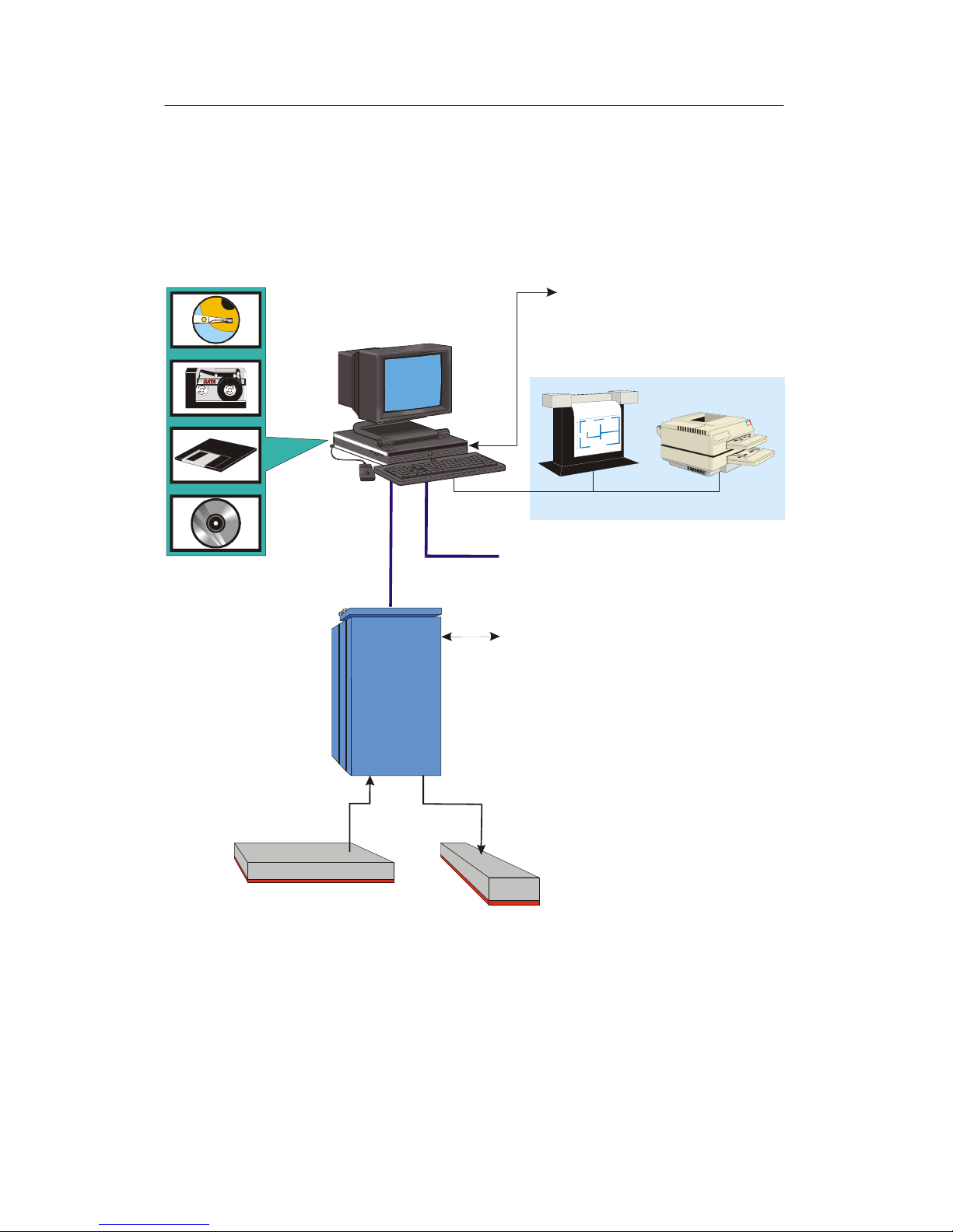
Transmit
transducer array
Operator Station
Receive transducer array
Interfaces:
Sound Speed Sensor
Tide
Center depth output
Ethernet and serial lines (data i/o)
Interfaces:
Positioning systems
Attitude (roll, pitch and heave)
Heading
Clock
Trigger input/output
Clock synchronization
Internal
Ethernet
Optional
Ethernet
Colour printerA0 plotter
Optional eq uipment
(CD5401 / WMF / GIF)
Sub Bottom
Profiler
Transceiver
Unit
(Option)
Transceiver
Unit
Figure 1 EM 300 System drawing

Kongsberg Simrad EM 300 Base version
4
160719 /F
1.1 Characteristics
Main units
The Kongsberg Simrad EM 300 multibeam echo sounder consists
of the following units:
• Transmit transducer array
• Receive transducer array
• Transceiver Unit
• Operator Station
A complete mapping system will also include the following
additional units:
• vessel motion sensor(s)
• positioning system(s)
• sound speed sensor(s)
• postprocessing system
Transducer arrays
The transmit transducer array contains up to 8 modules in
accordance with the chosen beamwidth. Each module contains 108
elements arranged in rows of 6 elements. Each element is
individually connected to its corresponding transmitter in the
Transceiver Unit. It can thus be driven with an unique amplitude
level and phase to allow forming of the required transmit sectors
with individual steering.
The receive transducer contains up to 8 modules in accordance
with the chosen beamwidth. Each module contains 16 hydrophone
staves, and these have individual electrical connections to their
corresponding preamplifiers in the Transceiver Unit. Each stave
can thus be given unique amplitude and phase weighting to allow
forming of the required receive beams.
All cables are 15 m long underwater cables fitted with connectors
on the dry-end side. The cables normally enter the vessel through
tubes fitted with standard ship cable glands to provide water
tightness. If the tubes extend above the vessel’s water-line, divers
will in principle be able to replace faulty modules.
The modules are bolted down on a frame. These may be mounted
in a sea chest within a blister or directly to the hull with fairings.

System description
5
160719 /F
Transceiver Unit
The EM 300 Transceiver Unit contains the transmit and receive
electronics and processors for beamforming, bottom detection,
and control of all parameters with respect to gain, ping rate and
transmit angles. It has serial interfaces for all time-critical external
sensors such as vessel attitude (roll, pitch, heading and heave),
vessel position, and external clock. The Transceiver Unit is a wall
mounted cabinet with integrated shock and vibration absorbers.
The same cabinet is used for all combinations of beamwidths. An
Ethernet cable connects the Transceiver Unit to the Operator
Station.
Operator Station
The Operator Station is a high performance workstation running
Unix operating system. It contains the operator interface, displays
the collected data, and logs them to disk and tape.
The following data can be logged:
• depth
• seabed imaging
• vessel position and attitude
• sound speed data
• system installation and set-up parameters
The Operator Station converts range and angle data to “xyz” data
applying all corrections required by varying vessel attitude and
sound speed. Sound speed profiles may be loaded directly from a
sensor, or from an external computer, t o the Operator Station. The
system also supports use of a sensor to continuously read the sound
speed at the transducer depth.
The standard display functions on the Operator Station include all
those necessary for on-line quality control, in addition to coverage
plots and sensor calibration functions. From the Operator Station
full system diagnostics may be run on the Transceiver Unit.
Enhanced real-time displays include a seabed imaging display, and
merging of depth and position data to generate contour plots,
sun-illuminated depth plots, etc., to fully document the survey.
Software updates for all units are distributed on CD-ROM.

Kongsberg Simrad EM 300 Base version
6
160719 /F
2 OPERATIONAL PROCEDURES
2.1 Introduction
This chapter presents the most important operational procedures
required to operate the Kongsberg Simrad EM 300 multibeam
echo sounder.
The EM 300 is operated in on-line or off-line mode.
• The on-line mode is used during the survey. The applications
are then used to control the multibeam echo sounder, to store the
data, and to present various views of the data for quality
assurance. The on-line applications are started from the EM 300
Launchpad.
• The off-line mode is used after the survey has been completed,
and the data is stored on disk or tape. The applications are then
used to view the results of the survey.
The standard EM 300 applications will generate a full
documentation of the survey results, and will provide output for
survey statistics, contour charts, illuminated plots etc. For some
purposes this may be sufficient, but normally the post-processing
packages available are used for data cleaning, image processing
and final chart production.
The following main operational functions are described in this
chapter:
→ Starting the EM 300 system: page 8
→ Preparing the system for use: page 9
→ Running a survey: page 18
→ Closing down the EM 300 system: page 22
This chapter also presents a general description of the desktop
operational environment, and - in addition - the following special
subjects are described:
→ Installing software updates: page 24
→ Main Survey Display functions: page 55
→ System selftest: page 60
Operational procedures for the various additional utilities are not
found in this chapter. Refer to the applicable utility descriptions
further back in the book.

Operational procedures
7
160719 /F
2.2 Operational summary
To start the EM 300 system, follow this procedure:
1 Power up the system.
→ Refertopage8.
2 Log in.
→ Refertopage8.
3 Start the EM 300 application.
→ Refertopage9.
4 Check the installation parameters.
→ Refer to page 10 for clock adjustment and/or synchronization.
→ Refertopage11tocheckthewaterlevelsetting.
5 Check the runtime parameters.
→ Refer to page 11 for sound speed profile selection.
→ Refertopage 115tocheck and/or definemaximumandminimum
depth.
6 Start pinging.
→ Refertopage13.
7 Check the sensor functions and data.
→ Refertopage14.
8 Check the local depth and the main echo sounder f unctions
using the Ping and Survey Displays.
→ Refertopage14.
9 Enter the survey parameters.
→ Refertopage14.
10 Optionally; perform a system calibration.
11 Optionally; define or retrieve the planned job.
→ Refertopage17.
12 Measure sound speed profile at appropriate position in
survey area.
13 Move the vessel to the start of the first survey line.
14 Start logging.
→ Refertopage18.
15 Run the survey.
16 Save the collected data.
17 Power down.

Kongsberg Simrad EM 300 / Base version
8
160719 / /F
2.3 Starting the EM 300
Power on
To switch power on, follow this procedure:
1 Switch on the power on the EM 300 Processing Unit.
- It has an on/off switch on the front panel.
- The load process takes a few minutes, and will not be
terminated until approximately two minutes after you
have powered up the Operator Station.
2 Power up the Operator Station peripherals.
- Your system includes a number of peripheral devices.
Consult the applicable manufacturer’s documentation.
3 Power up the EM 300 Operator Station.
Software initialization
The operating system in the EM 300 Operator Station loads
automatically. When the boot process is finished, the display
presents the log-in dialogue box:
Welcome to [host name]
1 Enter your user name: em300
2 Press <Enter>.
When this log-in is completed, the system presents the EM 300
log-in dialogue box:
Welcome em300
3 Enter your password: simrad0
4 Press <Enter>.
- The system initiates the Common Desktop
Environment (CDE), and the following information is
presented:
• Icon dialogue box
• Common Desktop Environment (CDE) dialogue box
- These dialogue boxes are all standard applications
provided with the Unix operating system.

Operational procedures
9
160719 / /F
- You are now ready to start the EM 300 software.
5 Place the cursor in the background part of the display image.
6 Press the middle mouse button.
- A small menu is displayed on the screen. This menu
allows you to start the on-line applications (EM 300)
and/or the off-line applications, such as Merlin or
Neptune.
7 Select Start Operator Interface on the menu.
- The following applications and dialogue boxes are
automatically started:
• Launchpad
• Ping Display
• Runtime Menu
• Survey Display
- Note that the dialogue boxes appear in different
workspaces. You can select either one of these on the
Launchpad, or in the CDE dialogue box.
Launchpad introduction
The EM 300 Launchpad is the control dialogue box forthe EM 300
on-line operations. This utility provides realtime monitoring of the
storage capacity, sounder parameters and sensor status. It also
contains buttons to start and stop the echo sounder and the logging,
as well as controls to select the active workspace. The icons are
used to activate the other applications provided for the EM 300
on-line operations, while the bottom field identifies the operator
and the current survey.
→ The EM 300 Launchpad is described in detail on page 63.
2.4 Planning and calibration
Survey plan
As a general rule, the survey should be properly planned. The plan
can be based upon a chart where the planned survey lines are
plotted. General knowledge about the bottom conditions may be
useful.
→ Survey planning is described in more detail on page 298.
When the EM 300 system was installed, the physical locations of
sensors and peripherals were defined, and the appropriate settings
were made to the EM 300. These settings include:

Kongsberg Simrad EM 300 / Base version
10
160719 / /F
• Physical location of the transducer arrays and the sensors
• Serial lines set-up
• Offset definitions
If any of these settings have changed, the system parameters must
be adjusted accordingly before the survey starts.
→ This hardware set- up is described on page 24.
Calibration
To ensure maximum reliability and accuracy from the system, the
EM 300 and externally connected sensors should be calibrated
before the start of a new survey.
→ A calibration procedure is described on page 264.
2.5 Installation and runtime parameters
This section discusses parameters that may need changes from
survey to survey. It is recommended that the installation
parameters are always checked. A list of these parameters and
settings should be kept in a safe and accessible place.
Installation parameters
→ A description of how to access installation parameters is on page 24.
Adjustment and synchronization
The system clock can be adjusted to show the same time and date
as an external clock, or the clock from the positioning system. This
is done automatically at the start of the new survey. You can
synchronize the internal system clock with a one pulse per second
(1PPS) signal, normally available from a GPS receiver. This
eliminates any drift of the system clock.
→ See Survey Setup on page 15.
You may - before the survey is identified in the Survey Setup
dialogue box - select the source for the clock adjustment.
1 Locate the Clock field in the installation menu, and select
synchronization from any of these sources:
• External clock
• Operator Station (for manual setting)
• Active Pos. System
2 Select clock offset if required.
 Loading...