

Kongsberg Seatex Seapath 200 Installation Manual

Seatex Seapath™ 200
Installation Manual
Issued: 2008-06-09

Blank page

Notice
• All rights reserved. Reproduction of any of this manual in any form whatsoever without
prior written permission from Kongsberg Seatex AS is forbidden.
• The contents of this manual is subject to change without notice.
• All efforts have been made to ensure the accuracy of the contents of this manual.
However, should any errors be detected, Kongsberg Seatex AS would greatly appreciate
being informed of them.
• The above notwithstanding, Kongsberg Seatex AS can assume no responsibility for any
errors in this manual or their consequences.
Copyright © 2008 by Kongsberg Seatex AS. All rights reserved.
Kongsberg Seatex AS
Pirsenteret, N-7462 Trondheim, Norway
Telephone: +47 73 54 55 00
Facsimile: +47 73 51 50 20
Duty phone: +47 73 50 21 11
E-mail:km.seatex@kongsberg.com
www.km.kongsberg.com/seatex
III

Blank page
IV

Revision log
Document ID Rev. Date Reason for revision Approved
(sign)
38120-GM-002 0 1997-10-31 First version FOS
1 1998-05-04 Added to description of installing
coax connector on superflex cable,
new output data formats and some
corrections.
2 1998-12-14 Upgraded with new MRU mounting
bracket and to correspond with
Seapath version 1.02.03 and MRU
version 2.53.
3 1999-11-30 Updated to correspond with the
MRU 3.00 software version.
4 1999-12-30 Updated to include the new HW-
platform
5 2000-06-06 Updated to Seapath version 2.0
software
6 2000-11-22 Updated to correspond with latest
version of the Processing Unit with
analog output channels
7 2000-12-18 Corrected polarity for the RS-422
DB-9 connector, updated Installation
Worksheet with RS232/422
selection.
FOS
FOS
FOS
FOS
FOS
FOS
FOS
8 2003-02-12 Updated to correspond with Seapath
sw. version 2.02 and SCC version
2.1
9 2003-06-10 Updated with the possibility to
disable range rate corrections and
the change to LCD monitor
10 2004-03-30 Updated to correspond with Seapath
sw. version 2.03 and SCC version
2.1.3
11 2006-05-11 Updated to correspond with latest
PU hardware
12 2007-05-08 Updated 1PPS specification FOS
13 2008-06-09 Updated with recommendations on
antenna baseline length
V
FOS
FOS
FOS
FOS
FOS

Blank page
VI

Table of contents
1. INTRODUCTION ............................................................................................................... 1
1.1 About this manual ........................................................................................................ 1
1.2 References .................................................................................................................... 2
1.3 Definitions, abbreviations and acronyms ..................................................................... 2
1.3.1 Definitions ........................................................................................................ 2
1.3.2 Abbreviations and acronyms ............................................................................ 3
2. SPECIFICATIONS ............................................................................................................. 5
2.1 Physical dimensions ..................................................................................................... 5
2.2 Power ........................................................................................................................... 6
2.3 Environmental specification ........................................................................................ 6
2.4 Cable ............................................................................................................................ 7
3. INSTALLATION................................................................................................................. 9
3.1 General information ..................................................................................................... 9
3.2 Logistics ..................................................................................................................... 10
3.3 Location of the system parts ...................................................................................... 11
3.3.1 The GPS antennas .......................................................................................... 11
3.3.2 The MRU 5 ..................................................................................................... 12
3.3.3 The Processing Unit ....................................................................................... 13
3.3.4 The Video Display Unit ................................................................................. 13
3.4 Procedures .................................................................................................................. 13
3.4.1 Mechanical installation .................................................................................. 13
3.4.1.1 Installation procedure ....................................................................... 14
3.4.2 Electrical
3.4.2.1 MRU to Processing Unit cable wiring ............................................. 20
3.4.2.2 External input and output serial lines ............................................... 21
3.4.2.3 Ethernet connection .......................................................................... 23
3.4.2.4
3.4.2.5 Analog output ................................................................................... 24
3.4.2.6 Installation procedure ....................................................................... 25
3.4.3 Setup of configuration parameters ................................................................. 27
3.4.3.1 Lever arm vector determinations ..................................................... 27
3.4.3.2 Input data .......................................................................................... 28
3.4.3.3 Serial data output ............................................................................. 29
3.4.3.4 Setup procedure ................................................................................ 30
3.4.4 Calibration ...................................................................................................... 30
3.4.4.1 Calibration of the GPS antenna installation ..................................... 30
3.4.4.2
3.4.4.3 Calibration of MRU axis .................................................................. 35
installation ...................................................................................... 19
1PPS signal connection .................................................................... 23
Typical calibration procedure .......................................................... 31
VII

4. INSTALLATION DRAWINGS ....................................................................................... 37
5. APPENDIX A - INSTALLATION WORKSHEET ....................................................... 45
6. APPENDIX B - OUTPUT PROTOCOLS FROM SEAPATH ...................................... 51
6.1 NMEA format ............................................................................................................ 51
6.2 Binary format 3 .......................................................................................................... 53
6.3 Binary format, Simrad EM1000/950 compatible ....................................................... 54
6.4 Binary format, Simrad EM3000, EM300 and HiPap compatible .............................. 55
6.5 Calibration format ...................................................................................................... 56
6.6 Echo sounder format 9 ............................................................................................... 56
6.7 RDI ADCP format ...................................................................................................... 57
6.8 Binary format 11 ........................................................................................................ 57
6.9 Lehmkuhl gyro repeater format ................................................................................. 59
6.10 1PPS time tag, NMEA ZDA message ........................................................................ 59
6.11 1PPS time tag, Trimble compatible ........................................................................... 59
6.12 Atlas Fansweep format ............................................................................................... 60
6.13 Echo sounder format 18 ............................................................................................. 61
6.14 Submetrix format ....................................................................................................... 61
6.15 Cyclic redundancy check algorithm ........................................................................... 63
7. APPENDIX C - INSTALLATION OF COAX CONNECTORS ON SUPERFLEX
CABLE .................................................................................................................................... 65
8. APPENDIX D - SEAPATH CONFIGURATION SOFTWARE, SCC ......................... 71
8.1 Software installation .................................................................................................. 71
How to get started ...................................................................................................... 72
8.2
8.2.1 Starting the program ....................................................................................... 72
8.2.2
Setting the serial port parameters ................................................................... 74
8.2.3 Establishing connection ................................................................................. 74
8.3 General user interface ................................................................................................ 76
8.3.1 File menu ........................................................................................................ 76
8.3.1.1 Demo ................................................................................................ 76
8.3.1.2 Exit ................................................................................................... 76
8.3.2 W
8.3.3 View
izards menu ................................................................................................. 77
menu ..................................................................................................... 77
8.3.4 Help menu ...................................................................................................... 78
8.3.5 Tool buttons.................................................................................................... 78
8.3.6 Seapath Control Centre button ....................................................................... 79
8.3.7 Mouse operation ............................................................................................. 80
8.4 Editing parameter values ............................................................................................ 81
8.4.1 Vessel settings ................................................................................................ 81
8.4.1.1 Vessel geometry ............................................................................... 81
VIII

8.4.1.2 Vessel description ............................................................................ 82
8.4.2 GPS sensor settings ........................................................................................ 83
8.4.2.1 GPS geometry .................................................................................. 83
8.4.2.2 GPS processing ................................................................................ 83
8.4.2.3 GPS reference stations ..................................................................... 85
8.4.2.4 SBAS common settings .................................................................... 85
8.4.2.5 GPS antenna configuration .............................................................. 86
8.4.2.6 GPS attitude processing ................................................................... 91
8.4.3 MRU sensor settings ...................................................................................... 92
8.4.3.1 MRU geometry................................................................................. 92
8.4.3.2 MRU heave configuration ................................................................ 97
8.4.4 Measurement points ....................................................................................... 98
8.4.4.1 Measurement points geometry ......................................................... 98
8.4.5 Data
interface ................................................................................................. 99
8.4.5.1 Host
common ................................................................................... 99
8.4.5.2 Network common ........................................................................... 100
8.4.5.3 Input ............................................................................................... 101
8.4.5.4 Output ............................................................................................. 103
8.4.6 Parameter management ................................................................................ 108
8.4.6.1 Download ....................................................................................... 108
8.4.6.2 Upload ............................................................................................ 109
8.4.6.3 Save on file ..................................................................................... 109
8.4.6.4 Load from file ................................................................................ 110
8.4.6.5 Undo ............................................................................................... 110
8.4.6.6 Generate report ............................................................................... 111
Index ...................................................................................................................................... 113
Reader's comments .............................................................................................................. 115
IX

Blank page
X

List of illustrations
Figure 1 Dimensional drawing for the antenna holder ........................................................... 14
Figure 2 Top view of the Antenna Bracket ............................................................................ 14
Figure 3 The different components for mounting of the Antenna Bracket ............................ 15
Figure 4 Side view of the GPS antenna installation
Figure 5 Recom
Figure 6 Wall mounting of bracket with MRU connector pointing down ............................. 16
Figure 7 Sticker (4) shall indicate actual mounting orientation of MRU within bracket ...... 17
Figure 8 Junction box mounting............................................................................................. 18
Figure 9 Connection box mounting ........................................................................................ 18
Figure 10 Rear panel of the Processing Unit ......................................................................... 19
Figure 11 The offset vectors between the different components ........................................... 28
Figure 12 GPS Antenna Configuration .................................................................................. 32
Figure 13 Page 1 of GPS Antenna Calibration ...................................................................... 32
Figure 14 Page 2 of GPS Antenna Calibration ...................................................................... 33
Figure 15 Page 3 of GPS Antenna Configuration .................................................................. 34
Figure 16 Page 4 of GPS Antenna Configuration .................................................................. 35
Figure 17 Value of roll-error as function of vessel pitch angle as parameter and 1° and 2°
Figure 18 Installation Complete ............................................................................................. 71
Figure 19 SCC Start Window ................................................................................................. 72
Figure 20 Initial Offline Dialog ............................................................................................. 73
Figure 21 Seapath Control Centre, Main Window ................................................................. 73
Figure 22 Communication Setup ............................................................................................ 74
Figure 23 Connect Status ....................................................................................................... 75
Figure 24 Connected to Seapath ............................................................................................ 75
Figure 25 Setup icons
Figure 26 About SCC
Figure 27 Tool Buttons .......................................................................................................... 78
Figure 28 Keep Folder List Open ........................................................................................... 79
Figure 29 Close Folder List .................................................................................................... 79
Figure 30 Vessel 3D-View, Ghost mode ............................................................................... 79
Figure 31 Vessel Drop Down Menu ...................................................................................... 80
Figure 32 Vessel Geometry .................................................................................................... 82
Figure 33 Vessel Description ................................................................................................. 82
Figure 34 GPS Geometry ....................................................................................................... 83
Figure 35 GPS Processing Settings ........................................................................................ 84
Figure 36 GPS Reference Stations ......................................................................................... 85
Figure 37 SBAS Com
Figure 38 GPS Antenna Configuration .................................................................................. 87
Figure 39 Page 1 of GPS Antenna Calibration
Figure 40 Page 2 of GPS Antenna Calibration ...................................................................... 88
Figure 41 Stop Antenna Calibration ...................................................................................... 89
mended orientation of the MRU mounting bracket ...................................... 16
yaw misalignments ................................................................................................ 36
............................................................................................................. 77
............................................................................................................. 78
mon Settings for WAAS satellites ...................................................... 86
............................................................... 15
...................................................................... 87
XI

Figure 42 Page 3 of GPS Antenna Configuration .................................................................. 89
Figure 43 Edit Calibration Data ............................................................................................. 90
Figure 44 Page 4 of GPS Antenna Configuration .................................................................. 91
Figure 45 GPS Attitude Processing ........................................................................................ 91
Figure 46 MRU Geometry ..................................................................................................... 92
Figure 47 Step 1 of MRU Axis Orientation ........................................................................... 93
Figure 48 Step 2 of Manual MRU Axis Orientation .............................................................. 93
Figure 49 Step 3 of Manual MRU Axis Orientation .............................................................. 94
Figure 50 Positive offset angles rotations .............................................................................. 95
Figure 51 Step 2 of Auto MRU Axis Orientation .................................................................. 95
Figure 52 Step 3 of Auto MRU Axis Orientation .................................................................. 96
Figure 53 MRU Heave Filter ................................................................................................. 98
Figure 54 Measurement Points Geometry .............................................................................. 99
Figure 55 Com
Figure 56 Com
mon Host Settings ........................................................................................ 100
mon Network Settings .................................................................................. 101
Figure 57 Data Interface - Input Configuration ................................................................... 101
Figure 58 Serial Port Setting ................................................................................................ 102
Figure 59 Format Setting...................................................................................................... 102
Figure 60 RTCM Format Decoding ..................................................................................... 103
Figure 61 Formats available for device type Gyro ............................................................... 103
Figure 62 Data Interface - Output Configuration ................................................................. 104
Figure 63 Network Settings ................................................................................................. 104
Figure 64 Analog Settings .................................................................................................... 105
Figure 65 Measurement Point .............................................................................................. 105
Figure 66 Message Interval Settings .................................................................................... 105
Figure 67 Selection of NMEA output standard .................................................................... 106
Figure 68 Format Settings .................................................................................................... 106
Figure 69 Analog Format Settings ....................................................................................... 107
Figure 70 Datawell Hippy compatible analog output signals .............................................. 107
Figure 71 Input of test voltage for the selected analog channel ........................................... 108
Figure 72 Download Parameters .......................................................................................... 108
Figure 73 Upload Parameters ............................................................................................... 109
Figure 74 Save on file
.......................................................................................................... 109
Figure 75 Load from file ...................................................................................................... 110
Figure 76 Undo
..................................................................................................................... 110
Figure 77 Generate configuration report .............................................................................. 111
Figure 78 Configuration report ............................................................................................ 111
XII

List of drawings
Drawing no. Title Revision No. of sheets
31438-ma-010 HW platform, Enclosure dimensions 4 1
38120-md-007 Seapath 200, Antenna Holder 4 1
hs-003-a MRU housing, External dimension 4 1
hs-016-b MRU-M-MB3 bracket, Hydrographic version 1 1
hs-014-a MRU junction box MRU-E-JB1, Layout and
ext. dimensions
M410-32 Processing Unit Connection Box 0 1
M320-42 Cable, Processing Unit Aux-Serial,
Analog Output
1 1
0 1
XIII

Blank page
XIV

Seatex Seapath 200 Installation Manual, rev. 13 Introduction
1. INTRODUCTION
1.1 About this manual
This manual contains the information necessary to install the Seapath 200 on a ship. For all
other product information, please consult the User's Manual, reference [3].
The Seapath 200 is a precise heading, attitude and position sensor based on a sophisticated
combination of DGPS carrier phase measurements and inertial sensor technology. To achieve
the specified accuracy of the product, the installation has to be properly done and the
installation procedures in this manual have to be followed.
This manual is organised into the following chapters:
Chapter 1 Introduction - A brief presentation of the Installation Manual with references
and abbreviations.
Chapter 2 Specifications - Describes the physical dimensions, required power,
environmental and cable specifications.
Chapter 3 Installation - Presents procedures to be followed for a typical ship installation
with recommendations on location of the different parts, mechanical and electrical
installation, and how to set up and calibrate the product.
Chapter 4 Installation Drawings - Contains outline drawings showing the mechanical
dimensions of the different parts of the Seapath 200.
In this manual the following notations are used:
CAUTION
Is used to make the user aware of procedures and operational practice which, if not
followed, may result in degraded performance or damage to the equipment.
Note A note text has this format and is used to draw the user's attention to special
features or behaviour of the equipment.
1

Seatex Seapath 200 Installation Manual, rev. 13 Introduction
1.2 References
[1] NMEA 0183 Standard for interfacing marine electronic devices, Version 2.3
[2] RTCM recommended standards for differential Navstar GPS service, Version 2.2
[3] 38120-GM-001, User's Manual, Seapath 200, rev. 14
1.3 Definitions, abbreviations and acronyms
1.3.1 Definitions
alignment
antenna bracket
antenna holder
attitude
heading
heave
host system
pitch
Is the process of adjusting the current internal navigation
frame (g, h or b-frame) in the instrument to the true external
frame.
Is the arrangement for mounting the GPS antennas.
Is the arrangement on board the vessel for mounting the
antenna bracket to.
The orientation relative to the vertical axis of a vehicle.
Heading is not included. If heading is included the word
orientation for the vehicle is used.
The direction of the main axis (bow direction) of the vehicle
as opposed to course, which is the direction of motion of the
vehicle. Yaw angle as defined here is the same as heading.
The vertical dynamic motion of a vehicle and defined positive
down. Heave position and velocity are dynamic motion
variables with a certain lower cutoff frequency.
In this manual defined as Navigation computers, Dynamic
Positioning Systems, etc., receiving data from Seapath.
A rotation about the pitch axis is positive when the bow
moves up. Normally pitch means the dynamic pitch angle
motion.
roll
starboard
yaw
A rotation about the roll axis is positive when starboard side
of the vehicle moves down. Normally roll means the dynamic
roll angle motion.
When looking in the bow direction of a vehicle this is the
right hand side of the vehicle.
A rotation about the vertical axis is positive when turning
Eastward (Clockwise) when the vehicle cruises in North
direction. Normally yaw means the dynamic yaw motion.
2

Seatex Seapath 200 Installation Manual, rev. 13 Introduction
1.3.2 Abbreviations and acronyms
b-frame
CEP
CG
EMI
g-frame
GPS Time
IMU
LGND
MP
MRU 5
NMEA
P-axis
PGND
PPM
1PPS
RFI
RMS
R-axis
SBAS
SCC
UTC
Y-axis
Body frame. An orthogonal frame fixed to the MRU housing or to the
vehicle where the MRU is fixed.
Circular Error Probability.
Centre of gravity. The mass centre of a vessel. This is normally the location
with least linear acceleration, and hence the best location for measurements
of roll and pitch.
Electromagnetic interference.
Geographic frame. An orthogonal frame having axes pointing North, East,
and Down at the current location of the vehicle.
The time in the GPS system. The GPS time is within UTC time ±180 nsec
(95 per cent) plus leap seconds.
Inertial Measurement Unit. A system consisting of gyros and
accelerometers.
Logic Ground.
Measurement Point.
Motion Reference Unit, model 5. This is the IMU within the Seapath
measuring dynamic linear motion and attitude.
National Marine Electronics Association. NMEA 0183 is a standard for
interchange of information between navigation equipment.
This axis is fixed in the vehicle, and points in the starboard direction
horizontally when the roll angle is zero. Positive rotation about this axis is
bow of the vehicle up.
Power Ground.
Parts per million.
One Pulse Per Second.
Radio Frequency Interference.
Root Mean Square.
This axis is fixed in the vehicle, and points in the forward direction
horizontally when the pitch angle is zero. Positive rotation about this axis is
starboard side of the vehicle down.
Satellite Based Augmentation System
Seapath Control Centre is special software used to set configuration
parameters in Seapath. The software runs under Microsoft Windows version
95, 98, NT 4.0 or compatible on a PC.
Universal Time Co-ordinated. This is the official time in the world and has
replaced GMT (Greenwich Mean Time) as the official time.
This axis is fixed in the vehicle and points in the downward direction when
the vehicle is aligned horizontally. Positive rotation about this axis is
turning the bow of the vehicle to starboard.
3

Seatex Seapath 200 Installation Manual, rev. 13 Introduction
Blank page
4

Seatex Seapath 200 Installation Manual, rev. 13 Specifications
2. SPECIFICATIONS
2.1 Physical dimensions
Processing Unit
Width: ...................................................................................................... 482 mm (19-inch rack)
Height: .................................................................................................................... 132 mm (3 U)
Depth: .............................................................................................................................. 430 mm
Weight: ................................................................................................................................ 12 kg
Colour: ......................................................................................................... Front anodised black
Connection Box, M410-32
Length: ............................................................................................................................ 114 mm
Width: ................................................................................................................................ 89 mm
Height: ............................................................................................................................... 55 mm
Weight: ............................................................................................................................... 0.3 kg
Colour: .................................................................................................................................. Grey
Video Display Unit, 17" LCD (Samsung SyncMaster 710n)
Width: .............................................................................................................................. 380 mm
Height: ............................................................................................................................. 383 mm
Depth: .............................................................................................................................. 170 mm
Weight: ............................................................................................................................... 3.8 kg
Colour: ...................................................................................................................... Black/Silver
MRU 5
Height: ............................................................................................................................. 204 mm
Diameter: ......................................................................................................................... 105 mm
Weight: ............................................................................................................................... 2.5 kg
Colour: ................................................................................................................................... Blue
MRU Mounting Bracket, MRU-M-MB3
Length: ............................................................................................................................ 265 mm
Width: .............................................................................................................................. 119 mm
Height: ............................................................................................................................. 119 mm
Weight: ............................................................................................................................... 1.6 kg
Colour: ................................................................................................................................. Black
Material: .......................................................................................................................... POM-H
MRU Junction Box, MRU-E-JB1
Length: ............................................................................................................................ 226 mm
Width: .............................................................................................................................. 126 mm
Height: ............................................................................................................................... 90 mm
Weight: ............................................................................................................................... 2.0 kg
Colour: ................................................................................................................................. Black
5

Seatex Seapath 200 Installation Manual, rev. 13 Specifications
Antenna Bracket
Length ............................................................................................................................ 2560 mm
Height: ............................................................................................................................... 40 mm
Width: ................................................................................................................................ 75 mm
Weight for the 2.5-metre aluminium version ..................................................................... 6.6 kg
Colour: ................................................................................................................ Grey RAL 7035
2.2 Power
Processing Unit
Voltage: ....................................................................................... 85 to 135 and 180 to 265V AC
Power consumption: ............................................................................................... 100 W (max.)
Batteries: ...................................................................... None, connection to UPS recommended
Video Display Unit, 17" LCD (Samsung SyncMaster 710n)
Voltage: ........................................................................................... 100 to 240V AC (50/60 Hz)
Power consumption: .............................................................................................. 23 W (typical)
2.3 Environmental specification
Processing Unit
Enclosure material: ..................................................................................................... Aluminium
Enclosure protection: .......................................................................................................... IP-30
Operating temperature range: ...................................................................................... 0 to +55ºC
Operating humidity: ........................................................................................ 20 to 80% relative
Storage temperature range: ...................................................................................... -20 to +60ºC
Storage humidity: .................................................................................................. Less than 55%
Vibration testing according to: ..................................................................................... EN 60945
Connection Box, M410-32
Material: ..................................................................................................................... Aluminium
Enclosure protection: .......................................................................................................... IP-20
Video Display Unit, 17" LCD (Samsung SyncMaster 710n)
Operating temperature range: ...................................................................................... 5 to +40ºC
Relative humidity: ........................................................................................................ 20 to 80%
MRU 5
Enclosure material: ...................................................................................... Anodised aluminium
Enclosure protection: .......................................................................................................... IP-66
Operating temperature range: ..................................................................................... -5 to +55ºC
Operating humidity (max.): ................................................................................................. 100%
Storage temperature range: ...................................................................................... -20 to +70ºC
Storage humidity (max.): ..................................................................................................... 100%
Max. allowed vibration operational (10-2000 Hz continuous): ...................................... 0.5 m/s
2
6

Seatex Seapath 200 Installation Manual, rev. 13 Specifications
Max. allowed vibration non-operational (0-2000 Hz continuous): .................................. 20 m/s2
Max. shock non-operational (10 ms peak): .................................................................. 1000 m/s2
MRU Junction Box, MRU-E-JB1
Material: ..................................................................................................................... Aluminium
Enclosure protection: .......................................................................................................... IP-65
GPS Antennas (L1)
Enclosure material: ..................................................................................... Weatherable Polymer
Operating temperature range: ................................................................................... -40 to +70ºC
Operating humidity (max.): ................................................................................................. 100%
2.4 Cable
Cable MRU-E-CS1
Type: ...................................... Heavy Duty Screened, Habia Aquatherm RTFR 14x2x0.25 mm
Length: ................................................................................................................................... 3 m
Diameter: ........................................................................................................................ 13.5 mm
Flame retardation: ........................................................................................................ IEC 332-1
Insulation: ............................................................................................................................ ETFE
Screen: ............................................................................................................................ Cu-braid
Processing Unit to MRU Junction Box Cable
Type: ........................................................................................................ LAMAC 4x2x0.5 mm2
Maximum length: ............................................................................................................... 100 m
Diameter: ........................................................................................................................... 10 mm
Flame retardation: .................................................................................................... IEC 332-3/A
The GPS Antenna Cables (Coax)
Type: ................................................................................................... NK ½"-Superflex 50 BHF
Attenuation: ........................................................................................ 14 dB/100 m (at 1.6 GHz)
Maximum length (each cable): ........................................................................................... 100 m
Diameter: ........................................................................................................................ 13.2 mm
Minimum bend radius: ...................................................................................................... 32 mm
Flame retardation: ........................................................... CATV, UL1581, IEC 332-3, IEEE383
Coax connectors: .............................................................................. Huber+Suhner 11 N-50-9-9
2
7

Seatex Seapath 200 Installation Manual, rev. 13 Specifications
Blank page
8
Seatex Seapath 200 Installation Manual, rev. 13 Installation
3. INSTALLATION
3.1 General information
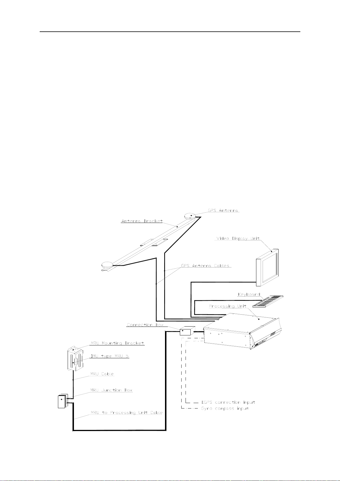
This chapter describes a typical ship installation of the Seapath system. The standard system
is supplied with the following parts:
• The Processing Unit.
• The Processing Unit connection box with 1.5-metre cable.
• Video Display Unit and standard keyboard.
• The MRU 5 unit.
• The MRU mounting bracket, MRU-M-MB3.
• Junction box, MRU-E-JB1, with three metres MRU-E-CS1 cable.
• Two GPS antennas.
• A 2.5-metre aluminium Antenna Bracket.
• Setup software, power cable, a null-modem configuration cable and documentation.
9

Seatex Seapath 200 Installation Manual, rev. 13 Installation
In addition to the above delivered parts, the following is needed:
• GPS antenna cables and the cable between the Processing Unit and the MRU junction
box.
• A 19-inch rack for mounting of the Processing Unit.
• Gyro compass data on a serial line (recommended).
• DGPS corrections on one or more serial lines for improved position accuracy
(recommended).
• Additional cables for input of Gyro compass data and DGPS corrections, and for output
lines to external equipment.
• Devices for reference measurements of roll, pitch and heading (for calibration).
• An external IBM-compatible PC with MS-Windows for setup and calibration.
General arrangement drawings of the ship should be acquired to simplify determination of
offsets between the GPS antennas, the MRU and the ship's centre of gravity (CG). Locations
for the various parts of the system must be decided, and mounting arrangement for the
Antenna Bracket and sufficient lengths of cable made available.
For external interfaces, electrical characteristics and data formats must be decided, and the
necessary cables and connectors made available. Power supply for the Processing Unit and an
external computer for setup and calibration are also needed.
An external heading reference, for example a surveyed quay is required for heading
calibration. For some applications, pitch and roll reference for calibration is also needed.
The MRU unit is shipped in a specially designed transportation container. Keep the MRU
within the container until everything is ready for installing the unit in the mounting bracket.
Note After the installation, please save the transportation container. The MRU must be
shipped in this container for service or repair to maintain the warranty.
3.2 Logistics
Safety: General safety guidelines to be followed when working in mast and on deck.
Personnel qualifications: Trained electrical workers.
Minimum number of personnel: 2, especially when mounting the Antenna Bracket to the Holder.
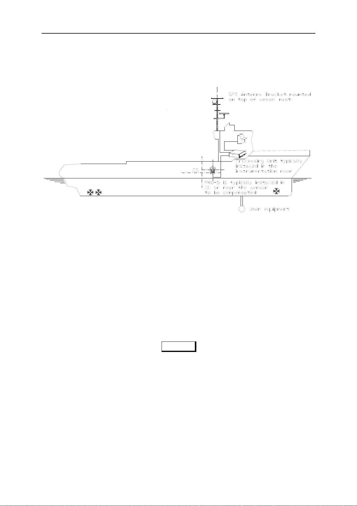
Ship location: The GPS antennas have to be mounted such that blocking of the GPS signal is
avoided. The MRU 5 unit is preferably mounted low in the ship or close to the system to be
compensated. The Processing Unit can be mounted on the bridge or in the instrument room.
Special tools required: A PC with Microsoft Windows 95, 98, NT version 4.0 or compatible.
10
Seatex Seapath 200 Installation Manual, rev. 13 Installation
3.3 Location of the system parts
The following sections contain hints regarding mounting of the various system parts:
3.3.1 The GPS antennas
For the GPS antennas, consider the following:
• The space above the antennas has to be free of obstructions of any kind. The antenna
should be protected from direct illumination of radar beams and other transmitting
antennas such as Inmarsat antennas. Seapath is more sensitive for blocking and reflections
(multipath) of GPS signals than GPS sensors that only utilises pseudo-range data. This
since Seapath also utilises carrier phase measurements for heading determination, and
both GPS antennas need to see at least two common satellites at the same time.
CAUTION
The GPS antennas have to be mounted in a way that avoids blocking of the GPS
signal.
• In order to reduce problems due to multipath effects the GPS antennas have to be mounted
above the nearest deck at a height which is equal to the width of this deck or more.
• The Antenna Bracket has to be mounted in such a way that torsion movement relative to
the ship's hull is kept at an absolute minimum.
Note If the Antenna Bracket supplied by Seatex is not used, it is important that the
antennas are rigidly mounted so that the distance between the antennas does not
change due to vibrations or accidental dislocation.
11

Seatex Seapath 200 Installation Manual, rev. 13 Installation
• The antenna baseline length is recommended in range 2.5 to 4.0 meters, but 1 to 5 meters
can be used. Maximum heading accuracy is achieved at 4.0 meters baseline.
• The maximum length for each of the antenna coaxial cables is 100 metres for the cable
type normally delivered with the system (1/2" Superflex). If longer cables are needed, a
low noise signal amplifier (LNA) should be fitted.
3.3.2 The MRU 5
For the MRU 5, consider the following:
• The unit is designed for installation in an indoor environment and for operation within its
temperature range.
• The unit is to be mounted close to the user equipment of which it is supposed to measure
the motion. This is to avoid errors in alignment with the user equipment and to eliminate
errors due to ship hull torsion.
• If the system is not allocated to measure motion of a particular user equipment, mount the
MRU as close to the ship's centre of gravity (CG) as possible. This to ensure best roll and
pitch measurements. If it is not possible to mount the MRU close to CG, try to mount it
along the longitudinal axis of the ship and as close to the CG as possible. Avoid mounting
the MRU high up or out to the side of the ship.
Be aware of:
• Vibrations. Direct mounting onto the main hull structure is preferable.
Note The worst mounting positions are thin walls that may come in resonance with
vibrations driven by machinery, propellers, pumps or motors. Avoid mounting the
MRU close to hydraulic pumps and valves where there are high frequency
vibrations.
• Temperature changes. For safe mounting of the MRU, place the unit in a location where
the temperature is low and where changes in temperature are slow. A location directly on
the hull far away from the heat of the machinery, heaters and air conditioning systems is
preferable.
• Corrosion problems. Place the MRU in a location where no direct splashing seawater is
present.
12

Seatex Seapath 200 Installation Manual, rev. 13 Installation
3.3.3 The Processing Unit
For location of the Processing Unit, consider the following:
• The unit is designed for indoor installation and should not be exposed to heavy vibrations,
transformers or similar.
• The unit should be mounted in a damped 19-inch rack to be in accordance with the
environmental standard IEC945/EN600945.
•
It is recommended that ventilation or air conditioning is provided in order to keep the
ambient operating temperature around +20°C. The best location is typically in the
instrument room or on the bridge mounted into a 19-inch rack with good ventilation.
• It is recommended that the area around the unit is kept free from dust and static electricity.
• The air inlet and outlet on the unit must not be blocked. The unit has an internal fan and
requires free airflow from the rear and out to the sides of the unit.
• All connections to the unit are on the rear side and available space for cable connections
and service must be provided.
3.3.4 The Video Display Unit
For location of the table mounted Video Display Unit, consider the following:
• The unit is designed for installation in an indoor environment and for operation within the
temperature range. The best location is typically on a table in the instrument room or on
the bridge mounted close to the Processing Unit.
• It is recommended that the area around the unit is kept free from dust and static electricity.
3.4 Procedures
3.4.1 Mechanical installation
The mechanical installation consists of:
• Making a holder for the Antenna Bracket and having it fastened in a suitable location in a
mast.
• Mounting the Antenna Bracket with the GPS antennas on a holder in the mast.
• Mounting the MRU bracket and the MRU near the user equipment for which attitude data
is wanted, or near the vessel's centre of gravity.
• Mounting the Processing Unit in a rack in the instrument room or bridge.
• Mounting the VDU close to the Processing Unit.
13

Seatex Seapath 200 Installation Manual, rev. 13 Installation
The installation procedure described below assumes that the Antenna Bracket delivered by
Seatex is used and that a holder for this Antenna Bracket is prepared in accordance with the
antenna holder drawing in chapter 4.
3.4.1.1 Installation procedure
The mechanical installation of the various parts is performed in the following steps:
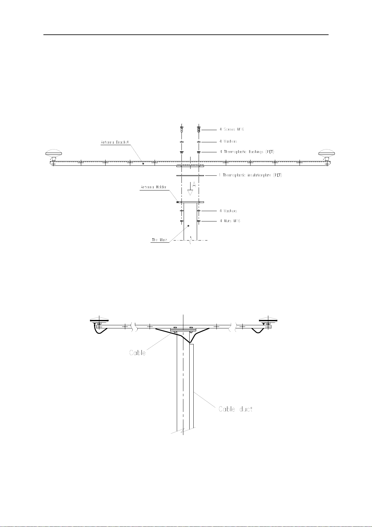
1. First the user has to make a holder for the Antenna Bracket (the holder is not part of the
Seapath delivery) and have it properly fastened to the mast in the preferred orientation
(horizontal or vertical). When the Antenna Bracket is mounted vertically, the drawings in
Figure 2, Figure 3 and Figure 4 are not correct.
Figure 1 Dimensional drawing for the antenna holder
2. Bring the Antenna Bracket, the two GPS antennas and the antenna cables as close as
possible to the location of the antenna holder. While both the GPS antennas and the
Antenna Bracket are down on deck, mount the GPS antennas on the Bracket with both
antennas oriented in the same direction. Depending on antenna type, labelling on the
antenna housing (arrow or text) or connector location is used to determine direction.
Figure 2 shows the antennas oriented with connectors pointing in the same direction. The
antennas are not marked, and are interchangeable but called no. 1 or 2 for reference. The
normal orientation of the Antenna Bracket is along ship with antenna no. 1 aft. It can,
however, be mounted in any orientation, provided it is approximately horizontal.
Note Both GPS antennas have to be mounted on the Bracket oriented in the same
direction, otherwise the system will have degraded heading performance.
Figure 2 Top view of the Antenna Bracket
The screws for mounting the GPS antennas to the Bracket must be secured with washers.
14
Seatex Seapath 200 Installation Manual, rev. 13 Installation
3. Connect the antenna cables to both GPS antennas. The connection between the antenna
and the antenna cable should be sealed against water penetration, preferably by using
waterproof self-vulcanising tape. The GPS antenna cables are then strapped inside the
Antenna Bracket as shown in Figure 4.
4. Lift the Antenna Bracket in the preferred direction on the holder.
Figure 3 The different components for mounting of the Antenna Bracket
Ensure that the delivered insulation plate is used between the Antenna Bracket and the holder,
and that the four bushings are placed in the mounting holes before the screws are entered. The
nuts should be secured with washers or by utilising self-locking nuts.
Figure 4 Side view of the GPS antenna installation
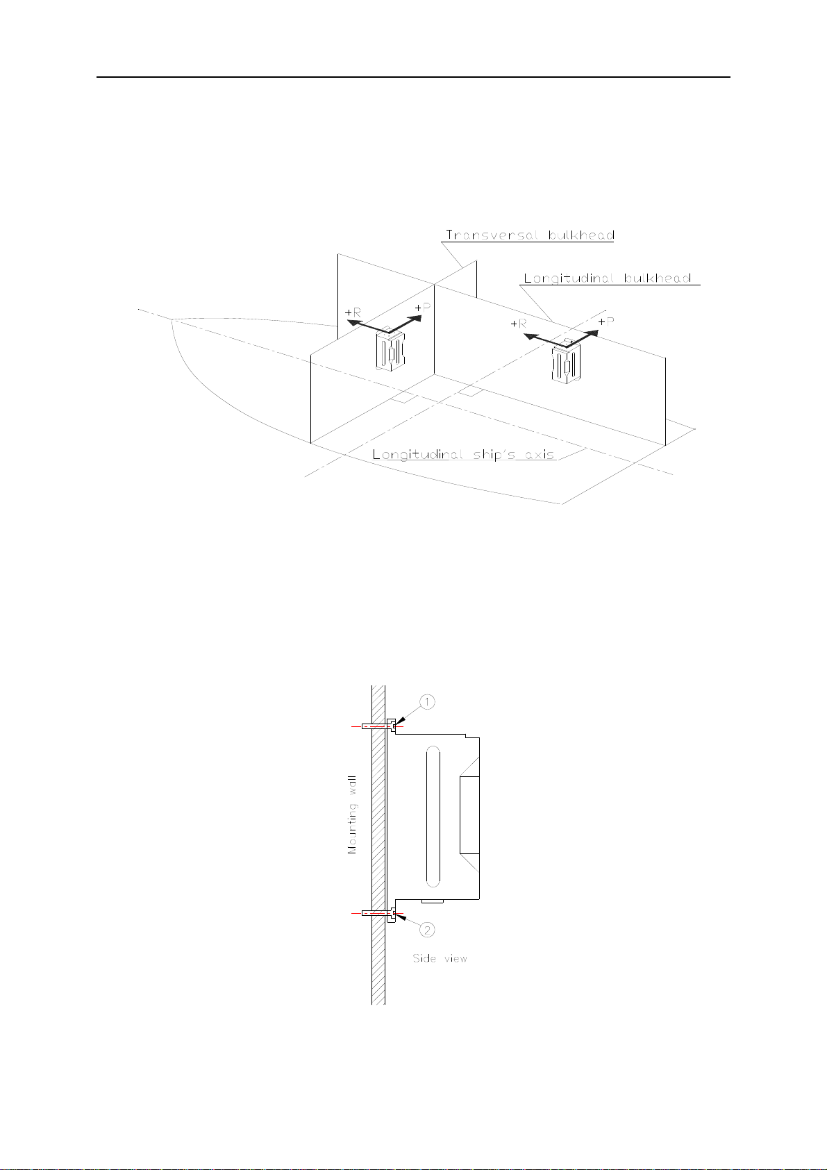
5. When the best mounting location for the MRU has been identified, place the MRU
mounting bracket in the preferred orientation and make screw holes in the foundation. If
the orientation of the bracket can be freely selected, mount the bracket on the longitudinal
15
Seatex Seapath 200 Installation Manual, rev. 13 Installation
or transversal bulkheads of the ship with the opening pointing downward, as shown in
Figure 5. This will ensure easy and accurate orientation of the MRU according to the
longitudinal axis. Reserve sufficient space below the bracket to allow insertion of the
MRU from below.
Figure 5 Recommended orientation of the MRU mounting bracket
6. Mount the MRU bracket on the wall, preferably with the opening pointing down, as
shown in Figure 6. Mark and drill a M6 hole for the top screw (1) and enter the screw
without tightening it completely. Align the bracket vertically using its own weight or by
aligning it in relation to the wall. Drill two holes for the lower screws (2) and insert and
securely tighten all three screws, using washers or self-locking nuts.
Figure 6 Wall mounting of bracket with MRU connector pointing down
16
 Loading...