

Kongsberg Seatex AIS 100 Instruction Manual
Seatex AIS 100
Instruction Manual

Blank page

iii
Document revisions
Document ID Rev. Date Reason for revision
0 - 3 Draft versions
4 2003-03-03 Updated NMEA descriptions
Man_instr_ais100_r5 5 2003-03-31 Minor update after internal revision
Software versions
This Instruction Manual applies to software version 1.06 and newer.

iv
Blank page

v
Table of contents
1 GENERAL INFORMATION ..................................................................1
1.1 Introduction............................................................................... 1
1.2 How to use this manual...............................................................1
1.3 References ................................................................................1
1.4 Abbreviations and acronyms ........................................................2
1.5 AIS – Automatic Identification System .......................................... 3
1.6 System components ...................................................................6
1.7 Electrical specifications................................................................8
2 OPERATION......................................................................................9
2.1 Introduction............................................................................... 9
2.2 Operational modes .....................................................................9
2.2.1 Autonomous and continuous mode................................. 9
2.2.2 Assigned mode ............................................................9
2.2.3 Polled or controlled mode............................................ 10
2.3 Malfunction and fallback arrangements ....................................... 10
2.4 Mobile station initialisation......................................................... 10
2.5 Overview................................................................................. 11
3 DISPLAY PAGES..............................................................................13
3.1 Main menu descriptions............................................................. 13
3.1.1 Navigational status..................................................... 13
3.1.2 Long range history ..................................................... 13
3.1.3 Voyage data .............................................................. 14
3.1.4 Static data ................................................................ 15
3.1.5 Dynamic data ............................................................ 16
3.1.6 Channel management................................................. 17
3.1.7 VHF link.................................................................... 18
3.1.8 Downperiods ............................................................. 18
3.1.9 Network & ports......................................................... 19
3.1.10 Answer modes........................................................... 19
3.1.11 Diagnostics ............................................................... 20
3.1.12 Security.................................................................... 21
3.2 Authorisation code entry ........................................................... 21
3.3 View page ............................................................................... 22
3.4 SMS menu............................................................................... 22
3.5 Alarms.................................................................................... 26
3.6 Adjusting brightness and contrast............................................... 26
4 TECHNICAL SPECIFICATIONS.........................................................27
4.1 Health, environment and safety ................................................. 27
4.2 Restrictions in guarantee...........................................................27

vi
4.3 Physical dimensions.................................................................. 27
5 INSTALLATION...............................................................................33
5.1 General...................................................................................33
5.2 AIS 100 MKD ........................................................................... 34
5.3 AIS 100 mobile station.............................................................. 35
5.4 AIS 100 connection box ............................................................ 37
5.5 External cabling of data signals.................................................. 41
5.6 AIS 100 VHF antenna................................................................ 42
5.7 AIS 100 GPS antenna ............................................................... 44
5.8 Internal alarm system............................................................... 46
6 EXTERNAL INTERFACES..................................................................47
6.1 External interfaces.................................................................... 47
6.2 Presentation interface ............................................................... 47
6.3 Long range interface.................................................................49
6.4 Sensor input............................................................................ 49
6.5 New IEC 61162-1 sentences...................................................... 51
6.6 IEC 61162-1, Ed. 2, sentences................................................... 70
6.7 Proprietary 61162-1 sentences................................................... 81
7 SOFTWARE SETUP PROCEDURE ......................................................85
7.1 Description of installation setup.................................................. 85
8 MAINTENANCE ...............................................................................89
8.1 General...................................................................................89
8.2 Periodic maintenance................................................................ 89
8.3 Repairs and modifications.......................................................... 89
8.3.1 Exchange of antenna cable..........................................90
8.3.2 Exchange of GPS or VHF antennas ............................... 90
8.3.3 Repair of the Seatex AIS 100....................................... 90
8.4 Installation of a spare Seatex AIS 100 ........................................ 91
9 TROUBLESHOOTING .......................................................................93
9.1 Hardware problems .................................................................. 93
9.1.1 Power supply failing.................................................... 93
9.1.2 GPS and VHF antenna cable connections.......................93
9.1.3 GPS and VHF antenna malfunction ............................... 93
9.1.4 GPS receiver failing .................................................... 94
9.1.5 VHF transceiver failing ................................................ 94
9.2 External data interface problems ................................................ 94
9.2.1 Data input from main GPS/GNSS source ....................... 94
9.2.2 Heading from vessel heading sensor............................. 95
10 PARTS LIST ....................................................................................97
APPENDIX A – VESSEL TYPES ................................................................99
APPENDIX B – DECLARATION OF CONFORMITY...................................101
INDEX .................................................................................................103

vii
List of illustrations
Figure 1 Elements in an AIS system............................................................4
Figure 2 AIS 100 system components .........................................................6
Figure 3 Front display MKD unit................................................................ 11
Figure 4 MKD unit dimensions .................................................................. 27
Figure 5 Mobile station dimensions ........................................................... 28
Figure 6 Connection box dimensions ......................................................... 29
Figure 7 VHF antenna.............................................................................. 30
Figure 8 GPS antenna and pole dimensions................................................31
Figure 9 Rear side of the MKD unit and interconnection plug........................34
Figure 10 The Amphenol connector...........................................................35
Figure 11 Recommended free space to rear side of mobile station ................ 36
Figure 12 Rear side of mobile station ........................................................ 36
Figure 13 The 9-pin D-sub plug................................................................37
Figure 14 Recommended free space to rear side of connection box...............38
Figure 15 The 50-pin plug........................................................................40
Figure 16 Talker and listener cabling – data/shield...................................... 41
Figure 17 Third wire cabling..................................................................... 41
Figure 18 Recommended VHF antenna installation......................................42
Figure 19 VHF and GPS antenna cable connector termination.......................43
Figure 20 Recommended GPS antenna installation...................................... 44
Figure 21 GPS antenna offset arms...........................................................45
Figure 22 Interfaces to the Seatex AIS 100 mobile station...........................47

viii
Blank page

Seatex AIS 100 Instruction Manual, rev. 5 General information
1
1 GENERAL INFORMATION
1.1 Introduction
Congratulations on the purchase of your new Seatex AIS 100 and
thank you for selecting what is one of the best AIS systems available
on the market today.
Kongsberg Seatex AS manufactures several positioning and
navigation products for all types of vessels, from fishery and merchant
marine vessels to advanced offshore and research vessels. Kongsberg
Seatex AS is located in Trondheim in the central part of Norway. The
company's involvements in positioning and navigation products began
in 1984 with equipment for offshore and research vessels. Professional
mariners around the world acknowledge the Seatex brand names as
the "leading edge" in advanced, accurate and reliable navi gation and
positioning products.
1.2 How to use this manual
This manual is intended as a reference guide fo r operation, installation
and maintenance of the Seatex AIS 100 system. Great care h as been
taken to simplify the setup and operation of the system.
Please take the time to read this manual to get a thorough
understanding of the Seatex AIS 100's components and operation, as
well as their relationship to other sensors interfaced to the system.
Before going into details about the Seatex AIS 100 a short
introduction to AIS – Automatic Identification system is presented.
The mobile station will also be referred to as a transponder.
1.3 References
[1] IEC 61993-2. MARITIME NAVIGATION AND
RADIOCOMMUNICATION EQUIPMENT AND SYSTEMS Automatic Identification Systems (AIS) Part 2: Class A Shipborne
equipment of the Universal Automatic Identification System (AIS) Operational and performance requirements, methods of test and
required test results. Committee draft for vote 2001-02-16.
[2] RECOMMENDATION ITU-R M.1371. TECHNICAL
CHARACTERISTICS FOR A UNIVERSAL SHIPBORNE
AUTOMATIC IDENTIFICATION SYSTEM USING TIME DIVISION
MULTIPLE ACCESS IN THE VHF MARITIME MOBILE BAND.
Draft Revision.

Seatex AIS 100 Instruction Manual, rev. 5 General information
2
[3] IEC 60945 Maritime navigation and radio communication equipment
and systems -General requirements - Methods of testing and required
test results. Third edition.
[4] IEC 60950 Safety of information technology equipment. Edition 3.0,
1999-04.
[5] IEC 61162-1 Ed. 2.0 (2000-07) Maritime navigation and radio
communication equipment and systems - Digital interfaces - Part 1:
Single talker and multiple listeners.
[6] IEC 61162-2 Ed. 1.0 (1998-09) Maritime navigation and radio
communication equipment and systems - Digital interfaces - Part 2:
Single talker and multiple listeners, high-speed transmission.
1.4 Abbreviations and acronyms
ABK
Addressed and Binary Broadcast Acknowledgement
ABM
Addressed Binary and Safety Related Message
ACA
AIS Regional Channel Assignment
AIS
Automatic Identification System
ALR
Alarm
BIIT
Built In Integrity Tests
BS
Base Station
COG
Course Over Ground
DGPS
Differential GPS
DSC
Digital Selective Calling
ECDIS
Electronic Chart Display and Information System
ECS
Electronic Chart System
EMC
Electromagnetic Compatibility
ETA
Estimated Time of Arrival
FATDMA
Fixed Allocation TDMA
GNSS
Global Navigation Satellite System
GPS
Global Positioning System
HDG
Heading
IALA
International Association of Lighthouse Authorities
IEC
International Electrotechnical Commission
IMO
International Maritime Organisation
LAN
Local Area Network
LED
Light Emitting Diode
LR
Long Range
MKD
Minimum Keyboard Display
MMSI
Maritime Mobile Service Identity
MSG
Message
N/A
Not Applicable
NMEA
National Marine Electronics Association
PI
Presentation Interface
PPS
Pulse-per-second
PWR
Power
ROT
Rate of Turn
RTCM
Radio Technical Commission of Maritime Service

Seatex AIS 100 Instruction Manual, rev. 5 General information
3
RX
Receive
Seatex
Kongsberg Seatex AS
SOG
Speed Over Ground
SOTDMA
Self Organising TDMA
SWR
Standing Wave Ratio
TBD
To Be Defined
TDMA
Time Division Multiple Access
TX
Transmit
TXT
Text Message
UTC
Universal Co-ordinated Time
VDL
VHF Data Link
VDM
VHF Data Link Message
VDO
VHF Data Link Own Vessel Message
VHF
Very High Frequency
VTS
Vessel Traffic Service
1.5 AIS – Automatic Identification System
AIS is an identification system that uses VHF communication to
transmit and receive AIS data. AIS operates primarily on two
dedicated VHF channels, AIS 1 – 161,975 MHz and AIS 2 – 162,025
MHz. Where these channels are not avail able regionally, the AIS can
be set to alternate designated channels.
The AIS mobile station broadcasts the vessel's position, speed and
course over ground as well as static and voyage related information.
Short safety related text messages can be sent between vessels or
broadcast from shore based AIS stations or Aids to Navigation like
buoys and lighthouses. The on-board installed mobile station is
designed to operate automaticall y and as a stand-alone unit. When not
transmitting, the mobile station listens for position information from
other vessels or shore based stations.

Seatex AIS 100 Instruction Manual, rev. 5 General information
4
Figure 1 Elements in an AIS system
The system broadcasts data using the SOTDMA (Self-organised Time
Division Multiple Access) data protocol. Each minute is divided into
4500 time slots, enabling simultaneous transmission of up to 500
stations.
Coverage
The system radio coverage range is similar to other VHF applications
and is dependent on the height of the antenna. The propagation differs
from that of a radar, due to the longer wavelength, so it is possible to
"see" around bends and behind islands if the landmasses are not too
high. A typical value to be expected at sea is 20 nautical miles.
AIS Base Station
VTS Centre
GNSS Satellites
AIS VHF Lin
k
AIS VHF Lin
k

Seatex AIS 100 Instruction Manual, rev. 5 General information
5
AIS information content
AIS type of information is exchanged automatically between vessels,
vessels and shore based stations and vessel and Aids to Navigation
like buoys and lighthouses. The information transmitted by the AIS
mobile stations is grouped in four categories:
Static Data
• MMSI (Maritime Mobile Service Identity) number
• Call sign and name
• IMO number
• Length and beam
• Type of ship
• Location of position fixing antennas on the ship
Voyage Related Data
• Ship's draught
• Hazardous cargo type
• Destination and ETA (at Master's discretion)
Dynamic Data
• Position with accuracy indication and integrity status
• Time in UTC
• COG (Course over ground)
• SOG (Speed over ground)
• Heading
• Navigational status
• Rate of turn
Safety-related Messages
• Reading and writing short safety related messages
Data reporting and transmission rates
AIS data as stated above is autonomously sent at different update rates
and thus reporting rates are dependent on the ship's navigational
mode. Dynamic information is dependent on speed and course
alteration while static and voyage related data are transmitted every 6
minutes or on request. Thus fast ferries will report their navigational
data at a higher update rate than ships at anchor.
Seatex AIS 100 Instruction Manual, rev. 5 General information
6
Type of Ship Reporting
Interval
Ship at anchor 3 min.
Ship 0 to 14 knots 12 sec.
Ship 0 to 14 knots and changing course 4 sec.
Ship 14 to 23 knots 6 sec.
Ship 14 to 23 knots and changing course 2 sec.
Ship > 23 knots 3 sec.
Ship > 23 knots and changing course 2 sec.
All data input to the AIS mobile stations is based on the NMEA 0183
data protocol. Messages sent on VHF are based on the AIS data
protocol, which defines several Message Types containing different
types of information.
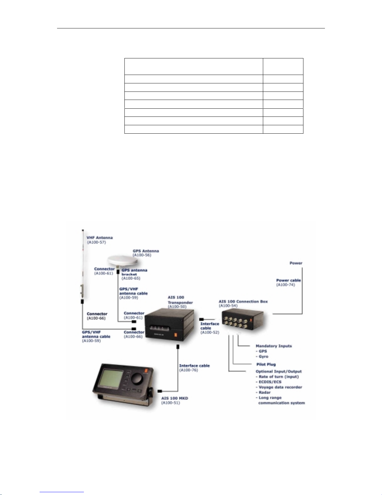
1.6 System components
The Seatex AIS 100 system consists of the following units:
Figure 2 AIS 100 system components

Seatex AIS 100 Instruction Manual, rev. 5 General information
7
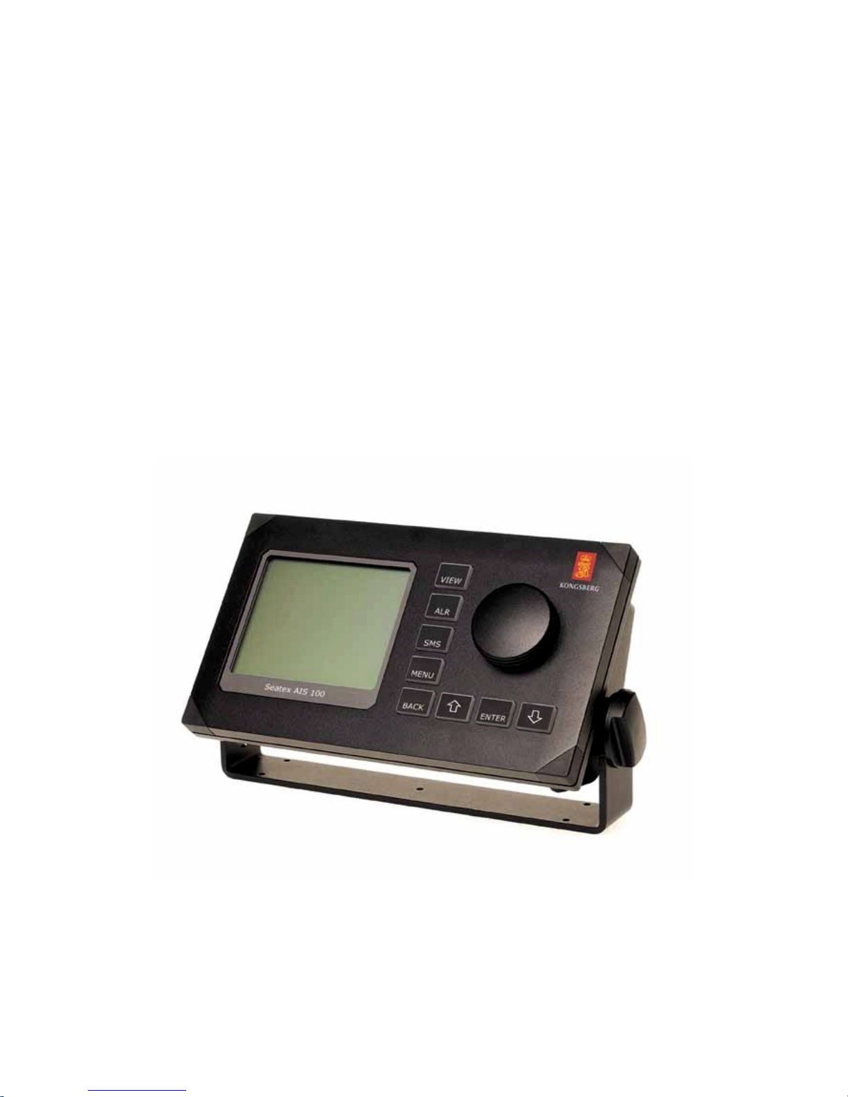
AIS 100 Minimum Keyboard and Display (MKD)
The MKD unit provides a simple user interface to the mobile station.
The keypads on the MKD can be used to navigate between dedicated
menus used for configuration and display of vessel navigation data.
Text messages can also be entered into the MKD and transmitted to
other vessels or shore based AIS stations providing warnings or other
relevant navigation information. Thus the MKD provides basic
presentation of configuration data, position data and text messages. If
the AIS has been interfaced to the on-board ECDIS s ystem or radar
the information displayed on the MKD can also be displayed on an
AIS compatible ECDIS or ECS systems.
AIS 100 mobile station
The mobile station incorporates two VHF receivers, configured to
operate on the predefined AIS frequencies for the region, one VHF
transmitter transmitting on all required frequencies and one DSC
receiver. The mobile station also incorporates a GPS receiver and a
processor. The internal GPS receiver, which is capable of receiving
differential corrections for increased position accuracy, is used for
time synchronisation and as a backup position sensor. For AIS data
transmission, the Self Organised Time Division Multiple Access
(SOTDMA) data protocol is used. SOTDMA enables a large number
of vessels to receive and transmit AIS data at the same time.
Front LED indicators
The LED indicators on the front of the mobile station can be used to
monitor status as well as data reception and transmission.
Led Colour Description
TX Off
Amber
Green
Red
Transmitter idle
Transmitting on AIS channel B
Transmitting on AIS channel A
Transmitter turned off
MSG Off
Amber
Green
No message/report being received
Message/report received on channel B
Message/report being received on channel A
GPS Amber
Green
Indirect synchronisation free run
Internal GPS OK. GPS synch selected
ALM Off
Red
No alarm
Alarm. Alarm relay activated
PWR Green Indicates powered unit

Seatex AIS 100 Instruction Manual, rev. 5 General information
8
AIS 100 connection box
The connection box is used to connect to external sensors main
position sensor, heading sensor and rate of turn sensor (when
available). These sensors are mandatory while interfaces to electronic
hart systems and long range communication systems, are optional.
AIS compatible ECDIS/ECS systems are interfaced to the AIS
through serial line communication. Power is supplied to the AIS
mobile station through the connection box.
AIS 100 VHF antenna
The VHF antenna is used for VHF communication. The antenna is
connected to the mobile station using cables with attenuation less than
3 dB.
AIS 100 GPS antenna
The GPS antenna is an L1 antenna receiving signals from all visible
satellites. The antenna is hermetically sealed and the cable used to
connect the GPS antenna to the mobile station should be of a quality
that ensures minimum loss of signal, i.e. less than 20 dB.
1.7 Electrical specifications
Input supply
Supply voltage 18 - 35 V DC
Supply current
@ 24 V DC
1.0 A (no VHF Tx)
1.2 A ( 2 W) VHF
1.6 A (12 W) VHF
Serial port capability
Mode RS-422
Isolation 1 kV
Line tolerant min +/- 15 V DC
Line speed 1200 - 57600 bits/s
Talker capability max 8 listeners @120 Ohm
Listener load requirements 120 Ohm (recommended)
Network
Network speed 10 Mbit/s

Seatex AIS 100 Instruction Manual, rev. 5 Operation
9
2 OPERATION
2.1 Introduction
The AIS should always be in operation. It is recommended not to
switch off the AIS during port stays in order to provide information to
port authorities. In areas where piracy occurs, the master may switch
of the transmitter. If the transmitter is switched off, static data and
voyage related information will be stored.
2.2 Operational modes
After the unit has been installed and configured it operates
automatically without any user intervention. The mobile station has
three operational modes:
• Autonomous and Continuous mode
• Assigned mode
• Polled or Controlled mode
2.2.1 Autonomous and continuous mode
In the Autonomous and Continuous mode the mobile station
automatically defines its own reporting rate in accordance with its
navigational mode, speed and course. The unit also selects its own
data transmission slots. This is the normal mode for operation in all
areas but the mode may be switched to/from Assigned mode or Polled
or Controlled mode by a competent authority via a base station on
shore.
2.2.2 Assigned mode
A competent authority responsible for traffic monitoring may
remotely set transmission intervals and/or time slots for the vessel
mobile station. When operating in Assigned mode, the mobile station
will transmit position data on a slightly different format, AIS Message
Type 2, instead of the transmitted AIS Message Type 1. In Assigned
mode the mobile station does not change its reporting rate when
changing course and speed. Assignments are limited in time and will
be re-issued by the competent authority when needed. Thus, Assigned
mode only affects the transmission and not the reception of position
reports.

Seatex AIS 100 Instruction Manual, rev. 5 Operation
10
2.2.3 Polled or controlled mode
In this mode the mobile station will automatically respond to
interrogation messages from a ship or competent authority. The
response is transmitted on the channel where the interrogation
message was received. Operation in Polled or Controlled mode does
not conflict with operation in the other two modes.
2.3 Malfunction and fallback arrangements
The mobile station has built-in integrity testing to continuously verify
own operational status and notify user and external equipment if any
malfunction is detected. Part of this test monitors the transmitter and
receiver modules. Alarm status will be transmitted to the PI port in
addition to triggering the alarm relay.
Malfunction type Malfunction source
Tx malfunction
ID 001
Tx frequency is not locked or
Tx power is measured outside setting
SWR 3:1 malfunction
ID 002
SWR is measured to more than 3:1
ChA malfunction (RX1)
ID 003
ChA frequency is not locked
ChB malfunction (RX2)
ID 004
ChB frequency is not locked
Rx DSC malfunction
ID 005
Ch70 frequency is not locked
2.4 Mobile station initialisation
The mobile station will automatically switch on when power is
applied to the unit by connecting the power cable in the connection
box. There is no on/off switch and thus power is removed by
disconnecting the power cable in the connection box.
• After power has been applied, wait for the two-minute
initialisation period.
• At completed initialisation all LEDs will go amber.
• The mobile station is ready for operation when the GPS LED is
blinking at one-second intervals.
• The View page will appear on the MKD.
Seatex AIS 100 Instruction Manual, rev. 5 Operation
11
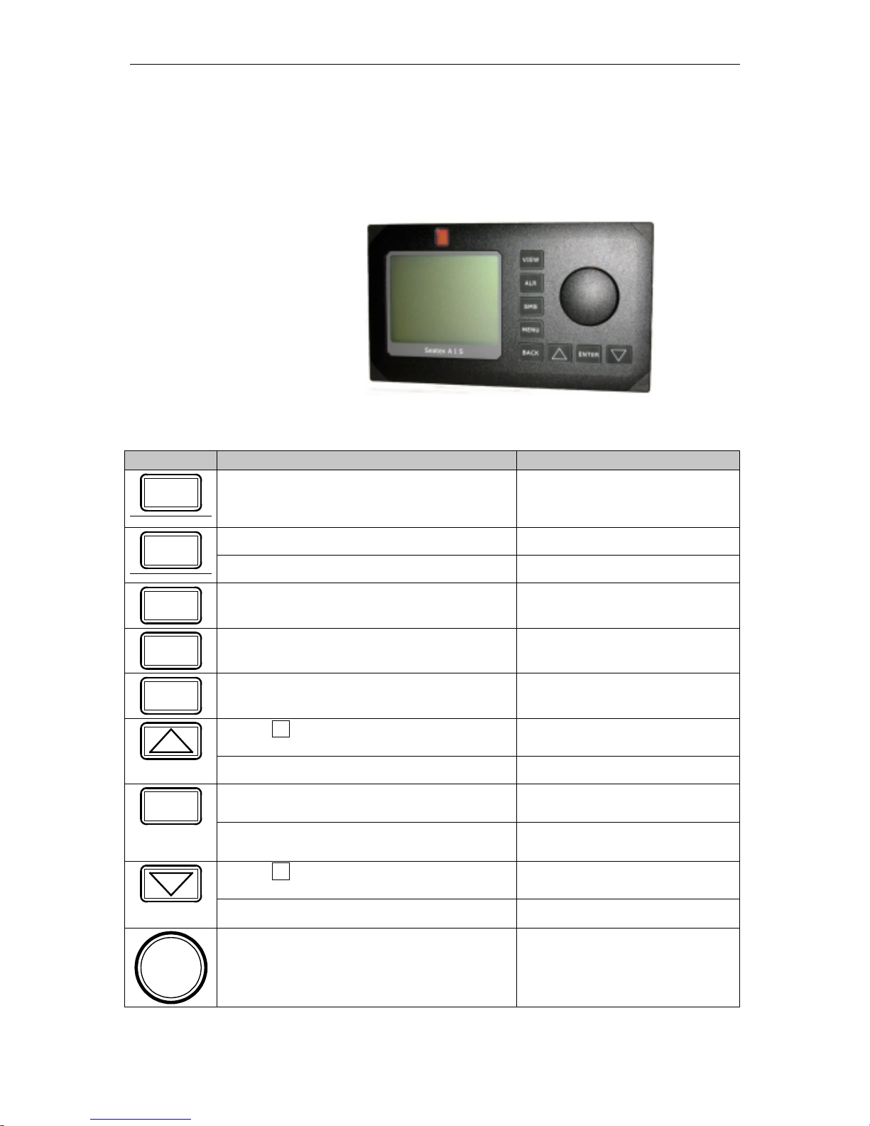
2.5 Overview
The default view of the display shows vessel own position along with
course (degrees) and speed (knots) over ground. Other vessels are
shown in ascending order relative to own vessel position.
Figure 3 Front display MKD unit
Buttons [Condition] Action Function
VIEW
[Always] Pressed once Displays the View page
[Always] Pressed once Displays the Alarms page
ALR
[Always] Pressed more than once Displays the Long Range page
SMS
[Always] Pressed Displays the SMS Menu page
MENU
[Always] Pressed Displays the Main Menu page
BACK
[Always] Pressed Displays the previous page
[When present in lower right corner]
Pressed
Displays previous subpage
[When writing/editing] Moves highlighting up
[When choice is highlighted] Pressed Selects highlighted choice
ENTER
[When nothing is highlighted] Pressed No action
[When present in lower right corner]
Pressed
Displays next subpage
[When writing/editing] Pressed Moves highlighting down
[When choice is highlighted] Rotated either
way
Moves highlighting

Seatex AIS 100 Instruction Manual, rev. 5 Operation
12
Blank page

Seatex AIS 100 Instruction Manual, rev. 5 Display pages
13
3 DISPLAY PAGES
The Seatex AIS 100 provides several display pages and menus
available for setup and display of information as well as editing of text
messages. In this chapter all display windows available are presented
and their contents discussed to enable easy operation and use of the
AIS mobile station.
3.1 Main menu descriptions
=== Main Menu ======== P1
1. Nav.Status
2. Long Range history
3. Voyage Data
4. Static Data
5. Dynamic Data
6. Chn.Management
7. VHF Link
8. Downperiods
9. Network & Ports
a. Answer Mode
b. Diagnostics
c. Security
1.06.zz
This is the Main Menu page. Press the MENU
button on the MKD unit to access the main menu.
The program version is shown in the lower part of
the page, where 1.06 is the version number and zz
the revision.
3.1.1 Navigational status
=== Nav Status ====== P11
Own Ship
AT ANCHOR
=== Choose from list ====
AT ANCHOR
UNDER WAY USING ENGINE
UNDER WAY SAILING
ENGAGED IN FISHING
NOT UNDER COMMAND
RESTR.MANOEUVRABILITY
CONSTRAINED BY DRAUGHT
MOORED
AGROUND
The Nav Status page enables the operator to
change the navigational status from a pre-defined
list. Options are AT ANCHOR, UNDER WAY
USING ENGINE, UNDER WAY SAILING,
ENGAGED IN FISHING, etc.
3.1.2 Long range history
=== Long Range ====== P12
Own Ship
LR INFO REQ. 03Jan 1230
lr info req. 01Jan 1145
lr info req. 01Jan 1134
The Long Range page contains active and
resolved Long Range interrogation requests.

Seatex AIS 100 Instruction Manual, rev. 5 Display pages
14
=== Requested Info = P121
BELLA
Name, Callsign, IMO
Position,COG,SOG
=== Choose from list ====
Send
Deny
If a new lr info req is selected, the name of the
requesting station will be displayed. The actions
available are send or deny the interrogation.
This page could also be accessed through the
Alarm page by selecting the LR alarm.
=== Provided Info = P121
BELLA
Name, Callsign, IMO
Position,COG,SOG
=== Choose from list ====
OK
Delete
Delete All LR
If a handled lr info req is selected, the provided
information will be displayed.
OK – keeps the message and exits the page.
Delete – deletes the message.
Delete All LR – deletes all LR messages.
3.1.3 Voyage data
=== Voyage Data ===== P13
Own Ship
Dest :HAMBURG
Eta :05022345
Drght :120
OnBrd :15
The Voyage Data page is used to input
information such as:
Dest: Destination of voyage.
ETA: Estimated time of arrival is displayed as
month, day, hour and minutes (MMDDHHMM).
Drght: Vessel draught.
OnBrd: Total number of people on board
Seatex AIS 100 Instruction Manual, rev. 5 Display pages
15
3.1.4 Static data
Static Data is used to enter static ship data, i.e. ship data that do not
change from one voyage to another. Static data should be entered
when installing the AIS mobile station.
=== Static Data ===== P14
Own Ship 1/3
Name :ANNE BERIT
Call :TA164GH
Mmsi :14395769235
Imo :10978974453
Type :51
Keel :12
The Static Data display window shows own
vessel static data such as:
Call: This is the vessel call sign.
MMSI: This is the vessel Maritime Mobile Signal
Identifier number.
IMO: This is the vessel IMO number.
Type: Type of vessel. ( See "Appendix A – Vessel
types")
Keel: height over keel. Total height of vessel in
metres.
=== Static Data ===== P14
Own Ship 1/3
Name :ANNE BERIT
Call :TA164GH
Mmsi :14395769235
Imo :10978974453
Type :51
Keel :12
In order to make changes to any static data field,
use the WHEEL to select desired line and confirm
with the ENTER button. Changing static data
could require an authorisation code to be entered
before data is entered depending on the security
setting
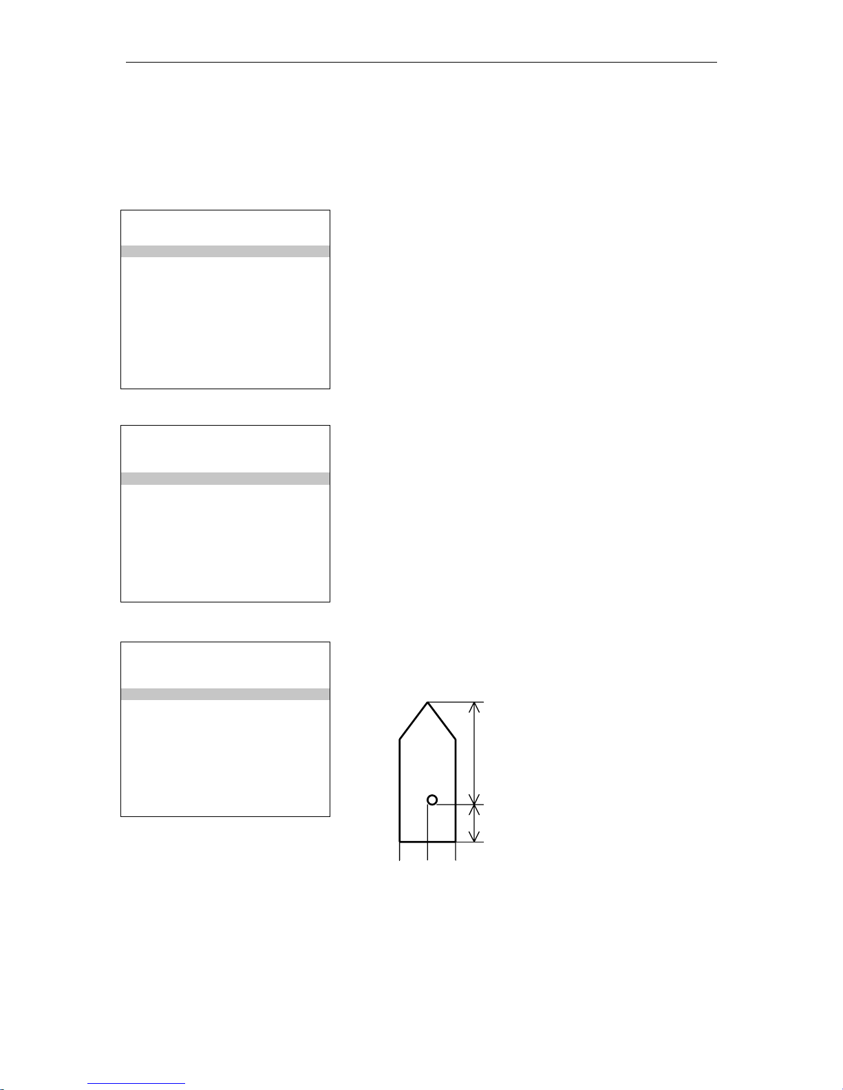
=== Static Data ===== P14
AIS Transceiver 2/3
Length A:30
Length B:10
Length C:7
Length D:7
The AIS transceiver entry specifies the antenna
location for the mobile station's internal GPS
receiver.
A
B
C
D

Seatex AIS 100 Instruction Manual, rev. 5 Display pages
16
=== Static Data ===== P14
AIS Transceiver 2/3
Length A:30
Length B:10
Length C:7
Length D:7
===Choose from list ====
Error. Continue Edit?
Abort menu page
If some of the static data parameters have been
input with a "zero" or "negative" number, you will
be prompted with the options: "Error. Continue
Edit?" or "Abort menu page". If "Error. Continue
Edit?" is selected, new parameters can be input as
described above. "Abort menu page" will keep the
previous data set.
=== Static Data ===== P14
GPS 2/3
Length A:30
Length B:10
Length C:7
Length D:7
========================
1234567890*< >
As for input of the position for the AIS Mobile
station antenna, the Static data GPS page enables
input of the vessel's main GPS/GNSS antenna
position.
3.1.5 Dynamic data
=== Dynamic Data ==== P15
Own Ship 1/2
LAT
:012°°°°13’23.56N
LON
:010°°°°24’13.73E
COG
:007.58°°°°
SOG :009.31Kn
HDG
:328.13°°°°
ROT
:001.32°°°°/min
EPFD :GPS
QUAL :DGPS SPS Mode
Dynamic data is the current status of the vessel.
These data are updated by the sensors and require
no manual data entry.
HDG and ROT requires an external HDG sensor.
If no sensor is connected, the default value is ---.-QUAL denotes the quality of the GPS signal,
either a DGPS or a standard GPS.
=== Dynamic Data ==== P15
Sensor Status 2/2
UTC Lost
Int. DGPS in use (msg17)
Internal SOG/COG in use
Heading valid
Other ROT source in use
Sensor status gives the current status of external
sensors.

Seatex AIS 100 Instruction Manual, rev. 5 Display pages
17
3.1.6 Channel ma nagemen t
=== Chn Management == P15
1. Edit Cur.Reg.
2. View Regions
3. Add Region .
Channel Management is used to configure
different radio channels for different chart zones.
Maximum 8 zones can be configured by input. A
zone is defined by the latitude and longitude of its
upper right (UR) corner and lower left (LL)
corner. When configured, the dedicated AIS
frequencies will automatically be used by the
system when the vessel position is inside the
geographically defined area. The main menu has
three options for channel management, which are
described in the following.
=== Edit Cur.Reg. ==== P151
RECTANGLE-2
ChnA :143
ChnB :144
RxTxMode :TxA/TxB,RxA/RxB
TxPower :High
LAT NE
:012°°°°13’23.56N
LON NE
:132°°°°36’14.02E
LAT SW
:034°°°°56’21.06N
LON SW
:125°°°°56’12.21E
BW A :Hi
BW B :Hi
Zone :2
The Edit Current Region page enables the
operator to change channels for the two AIS radio
receivers. The TxPower can only be set to High or
Low. If High is selected, the transmission power is
set to 12.5 W and if Low is selected, the
transmission power is set to 2 W. BW A and BW
B is the bandwidth settings for the VHF.
The selections are Default or Narrow. Default is
the maximum bandwidth allowed for this channel
(25 kHz or 12.5 kHz). Narrow denotes 12.5 kHz.
The user is only allowed to decrease the
bandwidth. Zone denotes the size of the transition
area in nautical miles outside of the region.
=== View Regions ==== P152
RECTANGLE-1 1/8
ChnA :143
ChnB :144
RxTxMode :TxA/TxB,RxA/RxB
TxPower :High
LAT NE
:012°°°°13’23.56N
LON NE
:132°°°°36’14.02E
LAT SW
:034°°°°56’21.06N
LON SW
:125°°°°56’12.21E
BW A :Hi
BW B :Hi
Zone :2
The View Regions page displays all defined
regions. This is a read only page and thus no
configuration changes can be made. The view
regions may consist of up to 8 pages and the
ARROW DOWN button can be used to display
more regions.

Seatex AIS 100 Instruction Manual, rev. 5 Display pages
18
=== Add Regions ====== P153
RECTANGLE-7
ChnA :56
ChnB :58
RxTxMode :TxA,RxA/RxB
TxPower :High
LAT NE
:012°°°°13’23.56N
LON NE
:132°°°°36’14.02E
LAT SW
:034°°°°56’21.06N
LON SW
:125°°°°56’12.21E
BW A :Hi
BW B :Hi
Zone :3
The Add regions page is for creating new regions
by manual input.
3.1.7 VHF link
=== VHF Link ======== P17
Ais Transceiver
ChnA :2087
ChnB :2088
TxPower :HIGH
BW A :Default
BW B :Default
Transmitter :TxON
The VHF link page displays the current VHF
settings. In addition to the normal VHF settings,
the transmitter can be turned off in this menu. This
option should only be used in situations where
transmission would endanger the ship, e.g. in warlike situations, piracy etc.
3.1.8 Downperiods
=== Downperiods ===== P18
From To
*01:30 20Nov 02:35 20Nov
11:00 19Nov 12:35 19Nov
16:20 16Nov 20:00 16Nov
11:30 15Nov 02:35 15Nov
*08:30 15Nov 02:35 15Nov
15:30 13Nov 02:35 13Nov
01.30 11Nov 02:35 11Nov
#11:30 10Nov 12:35 12Nov
#09:40 09Oct 10:10 09Oct
19:20 05Oct 15.10 06Oct
The Downperiods page displays when the mobile
station has been out of operation. Out of operation
is either when the power has been off, the
transmitter has been disabled (prefixed with #) or
when a TX malfunction has occurred (prefixed
with *).

Seatex AIS 100 Instruction Manual, rev. 5 Display pages
19
3.1.9 Network & ports
=== Network & Ports = P19
1. Serial Ports
2. Netw.Settings
The Network and ports page gives access to the
configuration settings for external serial ports and
network (LAN) settings.
=== Serial Ports === P191
External ports
PILOT :38400
PI :38400
LongRange :4800
RTCM :4800
SENSOR-1 :4800
SENSOR-2 :4800
SENSOR-3 :4800
The Serial ports page displays the baud rate for
all serial ports. Only the baud rates can be
changed. The sensor interfaces comply with
NMEA 0183.
=== Netw.Settings == P192
External ports
IP-adr :10.0.21.53
SubNet :255.255.255.0
Gateway :10.0.21.1
MAC MS :000.005.190
MAC LS :000.000.230
The Network page displays the network settings.
A network administrator for a Local Area
Network will provide the appropriate settings for
this page.
3.1.10 Answer modes
=== Answer Mode ==== P1a
Current Settings
Long Range :Automatic
VDL Response :On
====Choose from list ===
Manual
Automatic
The Answer mode page configures the polling
operation of the mobile station. The Long Range
requires additional external equipment for the
carrier system (Inmarsat …). The VDL response
configures the behaviour on normal VHF polling.
The normal operation is ON.

Seatex AIS 100 Instruction Manual, rev. 5 Display pages
20
3.1.11 Diagnostics
=== Diagnostics ===== P1b
1. Chn.Activity
2. Port Activity
3. SWR Levels
The Diagnostics page gives additional technical
and operational information about the system.
This is for service purposes by qualified
personnel.
=== Chn.Activity === P1b1
Last Activity On Chn
VDL TxA: Msg1 00:25
VDL TxB: Msg1 00:25
VDL RxA: Msg1 00:10
VDL RxB: Msg5 00:30
DSC Tx : Msg4 59:59
DSC Rx : Msg4 59:59
Displays the various messages received and
transmitted on VHF. The timestamp gives the
elapsed time, in minutes and seconds, since the
last event on the channel.
=== Port Activity == P1b2
Last Activity On Port
PI In : VDM 00:05
PI Out: VDO 00:03
LR In : LRI 01:00
LR Out: LR2 00:35
RTCM In : MSG 00:23
RTCM Out: MSG 00:10
SOR1 In : GGA 00:01
SOR2 In : HDT 00:05
SOR3 In : ROT 00:02
Displays the messages on the serial interfaces
timestamped as above.
=== SWR Levels ===== P1b3
Radio Measurements
Forward [W] : 2
Reflected [W] : 0.003
SWR : 1.1
This is for service purposes by qualified
personnel.

Seatex AIS 100 Instruction Manual, rev. 5 Display pages
21
3.1.12 Security
=== Security ======== P1C
Authorisation
L1 PIN Code :*******
L2 PIN Code :*******
Nav.Status :0
Voyage Data :0
Static Data :0
Chn.Mgmt :1
VHF Link :1
Serial Ports :1
Netw.Settings :1
Answer Mode :0
The Security page contains authorisation setup for
the mobile station. There are two authorisation
code levels. On this page the PIN codes can be set
and a number of menu pages can be protected
against unauthorised change. PIN codes, see
chapter 7. The Level 2 PIN code (L2) is valid on
all pages requiring L1 authentication1. The
possible levels are:
0 No authorisation code
1 Use L1 or L2 PIN code
2 Use L2 PIN code
All entries on this page are protected by L2 PIN
code.
3.2 Authorisation code entry
This page will appear when modifying data protected by the security
page.
========================
Enter authorisation code
PIN: **
========================
ABCDEFGHIJKLMNO
PQRSTUVWXYZ1234
567890.,!\”@<<<<←←←←↵↵↵↵
In order to enter the Authorisation code use the
WHEEL to select symbols and confirm each input
using the ENTER button. When all symbols in the
authorisation code have been input, select the ↵↵↵↵
symbol (confirming to the system that the last
symbol within the authorisation code has been
entered) and finally press the ENTER button.
1
Once authenticated with L1 or L2 PIN code, the authentication is valid until the View page has been displa yed
for 5 seconds or more. To protect the AIS security systems, the MKD returns to the View page when not used
for 15 minutes or more. In high security applications we recommend manually returning to the View page for 5
seconds or more when the change that required authentication is completed.

Seatex AIS 100 Instruction Manual, rev. 5 Display pages
22
3.3 View page
RANGE BRG NAME 1/2
00.12 123.1 ORION
00.12 123.1 ANDREAS
01.23 134.2 BERIT
03.34 145.3 SANANTONIO
05.45 156.4 HORNET
10.56 230.5 TORGEIR
30.67 023.6 HENNINSVÆR
40.78 302.7 STORFJORD
52.89 010.8 PANFISH
LAT: 63 26’31.20N TXOFF
LON:010 24’13.78E ALARM
SOG:024 COG:156 SMS
The View page is the default view on the MKD.
The View button will display this page.
Depending on the number of other vessels within
range, the number of pages will change
dynamically.
The lower part of the screen contains own vessel
information in addition to status of alarms and
events.
Name could be either MMSI number or name.
MMSI number is transmitted more frequently than
names.
Base stations use the MMSI prefixed with *.
RANGE BRG NAME 2/2
90.12 123.1 VIKTOR
98.12 123.1 DALSUND
99.99 134.2 ANKRABAD
99.99 145.3 OTTAR
99.99 156.4 VIKERSUND
LAT: 63 26’31.20N
LON:010 24’13.78E ALARM
SOG:024 COG:156 SMS
View page continued.
3.4 SMS menu
=== SMS Menu ========= P2
1. Inbox
2. Outbox
3. Predefined
4. Write Msg
5. Write SR Msg
6. Write BrcSR Msg
7. Write Pred. Msg
8. Clear Message Box
The SMS menu system contains the actions
related to the Short Messages System in the AIS.
 Loading...