

Kongsberg RADius 1000 Installation Manual

RADius 1000
Installation Manual
Issued: 2006-11-30

Blank page

III
Notice
• All rights reserved. Reproduction of any of this manual in any form whatsoever without
prior written permission from Kongsberg Seatex AS is forbidden.
• The content of this manual is subject to change without notice.
• All efforts have been made to ensure the accuracy of the contents of this manual.
However, should any errors be detected, Kongsberg Seatex AS would greatly appreciate
being informed of them.
Copyright 2006 by Kongsberg Seatex AS. All rights reserved.
Kongsberg Seatex AS
Pirsenteret, N-7462 Trondheim, Norway
Telephone: +47 73 54 55 00
Facsimile: +47 73 51 50 20
Duty phone: +47 73 50 21 11
E-mail: km.seatex@kongsberg.com
www.km.kongsberg.com/seatex

IV
Blank page
V
Revision log
Document ID Rev. Date Reason for revision Approved
(sign)
Man_inst_radius1000 0 2004-05-15 First version FOS
Man_inst_radius1000 1 2004-10-29 Issued after comments from
Kongsberg Maritime
TSW
Man_inst_radius1000 2 2004-12-06 Note on lithium battery TSW
Man_inst_radius1000 3 2005-02-07 Corrected cable part numbers TSW
Man_inst_radius1000 4 2006-02-20 Added new interface telegram
descriptions.
New installation cable part
number.
Added UPS recommendations
for transponders.
TSW
Man_inst_radius1000 5 2006-11-30 Updated manual to be
compatible with SW version
1.05.xx
FCC statement and RF
exposure info added, WEEE
note removed. Definitions
altered.
Transponder temperature range
adjusted and mean radiated
power inserted.
New Processing Unit front
view with LEDs
New and updated drawings
Change of note status from
Caution to Warning, page 25.
Dual interrogator information
added.
HR

VI
Blank page

VII
Table of contents
1. INTRODUCTION............................................................................................................... 1
1.1 About this manual ........................................................................................................ 1
1.2 FCC part 15 statement.................................................................................................. 1
1.3 FCC RF exposure compliance ..................................................................................... 2
1.4 References.................................................................................................................... 2
1.5 Definitions, abbreviations and acronyms..................................................................... 2
1.5.1 Definitions........................................................................................................ 2
1.5.2 Abbreviations and acronyms............................................................................ 3
2. SPECIFICATIONS............................................................................................................. 5
2.1 Physical dimensions..................................................................................................... 5
2.2 Input power supply....................................................................................................... 6
2.3 Interrogator radiated power.......................................................................................... 6
2.4 Environmental specification ........................................................................................ 7
2.5 Cables........................................................................................................................... 8
3. INSTALLATION ................................................................................................................ 9
3.1 General information ..................................................................................................... 9
3.2 Logistics ..................................................................................................................... 11
3.3 Location of the system parts ...................................................................................... 12
3.3.1 The Interrogator Unit ..................................................................................... 12
3.3.2 The Transponders........................................................................................... 14
3.3.3 Transponder Power Supply ............................................................................ 14
3.3.4 The Controller Unit ........................................................................................ 14
3.3.5 The Video Display Unit ................................................................................. 15
3.4 Installation procedures ............................................................................................... 15
3.4.1 Mechanical installation .................................................................................. 15
3.4.1.1 Interrogator installation procedure................................................... 16
3.4.1.2 Transponder installation procedure.................................................. 18
3.4.1.3 Transponder Power Supply installation procedure .......................... 19
3.4.1.4 Controller Unit installation procedure ............................................. 19
3.4.1.5 VDU installation procedure ............................................................. 19
3.4.2 Electrical installation...................................................................................... 19
3.4.2.1 External output serial lines............................................................... 20
3.4.2.2 Power/Connection Shelf .................................................................. 21
3.4.2.3 Interrogator data cable wiring .......................................................... 22
3.4.2.4 Interrogator power cable wiring....................................................... 23
3.4.2.5 High Gain Transponder power cable wiring and installation .......... 24
3.4.2.6 Low Power Transponder battery switch .......................................... 25
3.4.2.7 Interrogator Cable installation procedure ........................................ 25

VIII
3.4.3 Setup of configuration parameters ................................................................. 27
3.4.3.1 Select Interrogator Unit.................................................................... 27
3.4.3.2 Interrogator mounting angle............................................................. 28
3.4.3.3 Data output....................................................................................... 29
4. INSTALLATION DRAWINGS....................................................................................... 31
4.1 RADius Processing Unit, dimensions........................................................................ 32
4.2 RADius Controller Unit, dimensions......................................................................... 33
4.3 RADius Interrogator, dimensions .............................................................................. 34
4.4 RADius Transponder 500 Low Power, dimensions................................................... 35
4.5 RADius Transponder 600 High Gain, dimensions .................................................... 36
5. PARTS LIST ..................................................................................................................... 37
APPENDIX A - INSTALLATION WORKSHEET ............................................................ 39
APPENDIX B - OUTPUT PROTOCOLS............................................................................ 41
5.1 PSXRAD, NMEA proprietary format........................................................................ 41
5.2 Fanbeam BCD telegram............................................................................................. 42
5.3 Pseudo Artemis telegram ........................................................................................... 43
5.4 ABB DP telegram ...................................................................................................... 44
APPENDIX C - BULGIN CONNECTOR ASSEMBLY .................................................... 45
APPENDIX D - TRANSPONDER ID SETTINGS ............................................................. 47
APPENDIX E - TRANSPORTATION................................................................................. 49
Index ........................................................................................................................................ 51
Reader's comments ................................................................................................................ 53
IX
List of illustrations
Figure 1 RADius 1000 system, single Interrogator ................................................................. 9
Figure 2 RADius 1000 system, dual Interrogator .................................................................. 10
Figure 3 Typical operational scenario for a supply vessel operation, single Interrogator ...... 13
Figure 4 Typical operational scenario for a supply vessel operation, dual Interrogator......... 13
Figure 5 Interrogator mounting bracket ................................................................................. 16
Figure 6 Interrogator Unit mounted to mast or pole, top view .............................................. 16
Figure 7 Interrogator Unit mounted to rail, top view............................................................. 17
Figure 8 Dual Interrogator Unit mounted to mast or pole, top view...................................... 17
Figure 9 Transponder, rear and side view.............................................................................. 18
Figure 10 Rear panel of the Processing Unit ......................................................................... 20
Figure 11 Power and Data/LAN terminal rails for the Interrogator cables............................ 21
Figure 12 Pin numbers on Power terminal rail ...................................................................... 21
Figure 13 Pin numbers on Data/LAN terminal rail................................................................ 22
Figure 14 Inside view of data communication connector on the Interrogator Unit cable...... 22
Figure 15 Location of the data and power connectors on the Interrogator rear panel ........... 23
Figure 16 Inside view of power connector used on the Interrogator Unit cable.................... 23
Figure 17 Inside view of power connector on the Transponder cable ................................... 24
Figure 18 Transponder Power Supply cable connections ...................................................... 25
Figure 19 Processing Unit front view showing status LEDs ................................................. 26
Figure 20 System Configuration dialog box .......................................................................... 27
Figure 21 View Interrogator Units menu ............................................................................... 28
Figure 22 Measuring the mounting angle for the Interrogator............................................... 28
Figure 23 Interrogator mounting angle .................................................................................. 29
Figure 24 Data output configuration ...................................................................................... 29
Figure 25 Bulgin connector assembly.................................................................................... 45
Figure 26 Dangerous goods class 9 UN-3091........................................................................ 49
List of drawings
Drawing no. Title Revision No. of sheets
31438-MA-010 RADius Processing Unit, dimensions 4 1
3840-MD-041 RADius Controller Unit, dimensions 2 1
3840-MA-011 Interrogator, dimensions 3 1
3840-MA-020 Transponder, dimensions 1 1
3840-MA-026 Transponder dimensions, 600 High Gain 1 1

X
Blank page

RADius 1000 Installation Manual, rev. 5 Introduction
1
1. INTRODUCTION
1.1 About this manual
This manual contains the information necessary to install the RADius 1000 on a vessel. For
all other product information, please consult the RADius 1000 User's Manual, reference [2].
This manual is organised into the following chapters:
Chapter 1 Introduction - A brief presentation of the RADius 1000 Installation Manual with
references and abbreviations.
Chapter 2 Specifications - Describes the physical dimensions, required power,
environmental and cable specifications.
Chapter 3 Installation - Presents procedures to be followed for a typical ship installation
with recommendations on location of the different parts, mechanical and electrical
installation and how to set up the product.
Chapter 4 Installation drawings - Contains outline drawings showing the mechanical
dimensions of the different parts of the RADius 1000.
Chapter 5 Parts list - Lists the parts in the RADius 1000 system.
In this manual the following notations are used:
WARNING! Used when it is necessary to warn personnel that a risk of injury
or death exists if care is not exercised.
Caution! Used to warn the reader that a risk of damage to the equipment exists if
care is not exercised.
Note! Used to draw the reader's attention to a comment or some important
information.
1.2 FCC part 15 statement
This equipment has been tested and found to comply with the limits for a Class A digital
device, pursuant to Part 15 of the FCC Rules. These limits are designed to provide reasonable
protection against harmful interference when the equipment is operated in a marine and/or
commercial environment. This equipment generates, uses and can radiate radio frequency
energy and, if not installed and used in accordance with the instruction manual, may cause
harmful interference to radio communications. The equipment is not intended for operation in
RADius 1000 Installation Manual, rev. 5 Introduction
2
a residential area. Operation in such an area is likely to cause harmful interference in which
case the user will be required to correct the interference at his own expense.
Additional information to the user:
Changes or modifications not expressly approved by Kongsberg Seatex AS will void the
user's authority to operate the equipment.
1.3 FCC RF exposure compliance
This device conforms with FCC RF radiation exposure limits set forth for an uncontrolled
environment. The antenna used for this transmitter must be installed to provide a separation
distance of at least 20 cm from all persons and must not be co-located or operating in
conjunction with any other antenna or transmitter.
WARNING! The RADius must be mounted with a separation distance of at
least 20 cm from any humans.
1.4 References
[1] NMEA 0183 Standard for interfacing marine electronic devices, Version 2.3
[2] RADius 1000 User's Manual
[3] Man_inst_RADius_600X
[4] Man_inst_RADius_500X
1.5 Definitions, abbreviations and acronyms
1.5.1 Definitions
host system
In this manual defined as Navigation computers, Dynamic
Positioning Systems, etc, receiving data from RADius.
Interrogator
The Interrogator transmits signals and receives the reflected signals
from the Transponder(s). Based on this, it calculates the distance and
bearing to one or more transponders. Mounted on the DP vessel.
Transponder
The Transponder reflects the signals transmitted from the
Interrogator. Mounted on the remote object/vessel.
Latency
The time it takes from the actual measurement is made until the
telegram is transmitted on the serial port.

RADius 1000 Installation Manual, rev. 5 Introduction
3
1.5.2 Abbreviations and acronyms
AC
Alternating Current
BCD
Binary Coded Decimal
CU
Controller Unit
DP
Dynamic Positioning
DGPS
Differential Global Positioning System
EIRP
Equivalent Isotropically Radiated Power
EMC
Electromagnetic Compatibility
EN
European Norm
FBEAM
Fanbeam telegram format
FM-CW
Frequency Modulated Continuous Wave
FPGA
Field Programmable Gate Array
GND
Ground
GPS
Global Positioning System
GUI
Graphical User Interface
IEC
International Electrotechnical Committee
IP
Ingress Protection
IU
Interrogator Unit
LAN
Local Area Network
LED
Light Emitting Diode
NC
Not connected
NMEA
National Marine Electronics Association
RF
Radio Frequency
RMS
Root Mean Square
RX
Receive
TX
Transmit
UPS
Uninterruptible power supply used to ensure power in case of mains interrupt
VAC
Voltage Alternating Current
VDC
Voltage Direct Current
VDU
Video Display Unit
VGA
Video Graphic Adapter

RADius 1000 Installation Manual, rev. 5 Introduction
4
Blank page

RADius 1000 Installation Manual, rev. 5 Specifications
5
2. SPECIFICATIONS
2.1 Physical dimensions
RADius 1000 Controller Unit
See drawing 3840-MD-041, rev. 2, page 33, for physical description.
RADius 1000 Processing Unit
Width:...................................................................................................... 482 mm (19-inch rack)
Height:....................................................................................................................132 mm (3 U)
Depth: .............................................................................................................................. 430 mm
Weight: ................................................................................................................................ 12 kg
Colour:.........................................................................................................Front anodised black
Video Display Unit, 15" LCD
Width:.............................................................................................................................. 343 mm
Height:............................................................................................................................. 310 mm
Depth: .............................................................................................................................. 170 mm
Weight: ............................................................................................................................... 3.7 kg
Colour:................................................................................................................................. Black
RADius 1000 Interrogator Unit
Width:.............................................................................................................................. 562 mm
Height:............................................................................................................................. 412 mm
Depth: .............................................................................................................................. 184 mm
Weight: .................................................................................................................................. 7 kg
Colour:..................................................................................................................... White - front
Colour:.........................................................................................................................Grey - rear
RADius 500 Transponder
Width:.............................................................................................................................. 220 mm
Height:............................................................................................................................. 228 mm
Depth: ................................................................................................................................ 72 mm
Weight: ............................................................................................................................... 1.6 kg
Colour:..................................................................................................................... White - front
Colour:.........................................................................................................................Grey - rear
RADius 600 Transponder
Width:.............................................................................................................................. 220 mm
Height:............................................................................................................................. 228 mm
Depth: ................................................................................................................................ 72 mm
Weight: ............................................................................................................................... 1.4 kg
Colour:..................................................................................................................... White - front
Colour:.........................................................................................................................Grey - rear

RADius 1000 Installation Manual, rev. 5 Specifications
6
RADius Transponder Power Supply
Width:.............................................................................................................................. 126 mm
Height:............................................................................................................................. 226 mm
Depth: ................................................................................................................................ 90 mm
Weight: ............................................................................................................................... 2.5 kg
Colour:.................................................................................................................................. Grey
2.2 Input power supply
RADius 1000 Processing Unit
Voltage: ....................................................................................... 85 to 135 and 180 to 265V AC
Power consumption:............................................................................................... 100 W (max.)
Batteries: ...................................................................... None, connection to UPS recommended
Video Display Unit, 15"
Voltage: ........................................................................................... 100 to 240V AC (50/60 Hz)
Power consumption:..............................................................................................23 W (typical)
RADius 1000 Interrogator Unit
Voltage: ............................................. Provided from Power/Connection Shelf (48V DC ±10%)
Power consumption:................................................................................................. 70 W (max.)
Batteries: ...................................................................... None, connection to UPS recommended
RADius 500 Transponder
Voltage: .................................................................................................................. 3.6 V battery1
Power consumption:........................................................................................................... 7 mW
RADius 600 Transponder
Voltage: .....................................................................Supplied from Transponder Power Supply
Power consumption:............................................................................................700 mW (max.)
RADius Transponder Power Supply
Input voltage (universal): .................................................................................... 85 to 265 V AC
2.3 Interrogator radiated power
Peak radiated output power (EIRP): ................................................................................ 1.43 W
Mean radiated output power (EIRP): ................................................................................1.05 W
1
The RADius 500 contains a lithium battery. International regulations on shipment of lithium require special
warning labels. See Appendix E - Transportation in this manual for information on equipment containing lithium
batteries.

RADius 1000 Installation Manual, rev. 5 Specifications
7
2.4 Environmental specification
Products are compliant with relevant requirements in IEC/EN60945 and IEC/EN60950,
except for the listed Video Display which is not compliant to IEC/EN60945. Please contact
Kongsberg Seatex AS for a compliant version if required.
Processing Unit
Enclosure material:..................................................................................................... Aluminium
Enclosure protection: .......................................................................................................... IP-30
Operating temperature range:................................................................. -15 to +55ºC/5 to 131 F
Operating humidity: ........................................................................................20 to 80% relative
Storage temperature range: ...................................................................-20 to +60ºC/-4 to 140 F
Storage humidity: ..................................................................................................Less than 55%
Video Display Unit, 15"
Operating temperature range:...................................................................5 to +40ºC/41 to 104 F
Relative humidity:........................................................................................................20 to 80%
RADius 1000 Interrogator Unit
Enclosure material:............................................................................ Anodised aluminium - rear
Enclosure material:........................................................................................Plastic - front cover
Enclosure protection: .......................................................................................................... IP-66
Operating temperature range:.............................................................. -30 to +55ºC/-22 to 131 F
Operating humidity (max.):................................................................................................. 100%
Storage temperature range: .................................................................-25 to +70ºC/-13 to 158 F
Storage humidity (max.):.......................................................................................................60%
RADius 500 Transponder
Enclosure material:............................................................................ Anodised aluminium - rear
Enclosure material:........................................................................................Plastic - front cover
Enclosure protection: .......................................................................................................... IP-66
Operating temperature range:.............................................................. -30 to +55ºC/-22 to 131 F
Operating humidity (max.):................................................................................................. 100%
Storage temperature range: .................................................................-25 to +70ºC/-13 to 158 F
Storage humidity (max.):.......................................................................................................60%
RADius 600 Transponder
Enclosure material:............................................................................ Anodised aluminium - rear
Enclosure material:........................................................................................Plastic - front cover
Enclosure protection: .......................................................................................................... IP-66
Operating temperature range:.............................................................. -30 to +55ºC/-22 to 131 F
Operating humidity (max.):................................................................................................. 100%
Storage temperature range: .................................................................-25 to +70ºC/-13 to 158 F
Storage humidity (max.):.......................................................................................................60%

RADius 1000 Installation Manual, rev. 5 Specifications
8
RADius Transponder Power Supply
Enclosure material:..................................................................................................... Aluminium
Enclosure protection: .......................................................................................................... IP-65
Operating temperature range:................................................................. -15 to +55ºC/5 to 131 F
Operating humidity (max.):................................................................................................. 100%
Storage temperature range: .................................................................-25 to +70ºC/-13 to 158 F
Storage humidity (max.):.......................................................................................................60%
2.5 Cables
Possible cable types:
Interrogator to Processing Unit Data Cable
Type 1:.....................................Draka type TI (C) 60 V, shipline, 2x2x0.5 mm2 (Halogen free)1
Draka part number:......................................................................... 839202, El-number 1045881
Type 2:.................................... Draka type TI (C) 250 V, shipline, 2x2x0.5 mm2 (Halogen free)
Draka part number:.......................................................................................................... 832002,
Cable resistance, Type1 and Type 2: ........................................................................ 40 Ohm/km
Diameter overall, Type 1:............................................................................................... 6.5 ± 0.5
Diameter overall, Type 2:.................................................................................................. 6 ± 0.5
Maximum length: ................................................................................................................. 60 m
Flame retardation: ................................................................................................ IEC 60332-1/3
Interrogator Power Cable
Type:.............................................................................................................................. As above
Maximum length: ................................................................................................................. 60 m
Transponder Power Cable
Type:.............................................................................................................................. As above
Maximum length: ............................................................................................................... 200 m
Note! The data cable must be twisted pair cable! If other cable types are used the
maximum diameter should not exceed 7.5
±
0.5 mm.
1
This type is likely to be obsolete in 2006
RADius 1000 Installation Manual, rev. 5 Installation
9
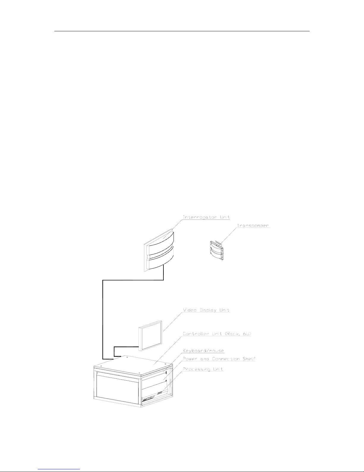
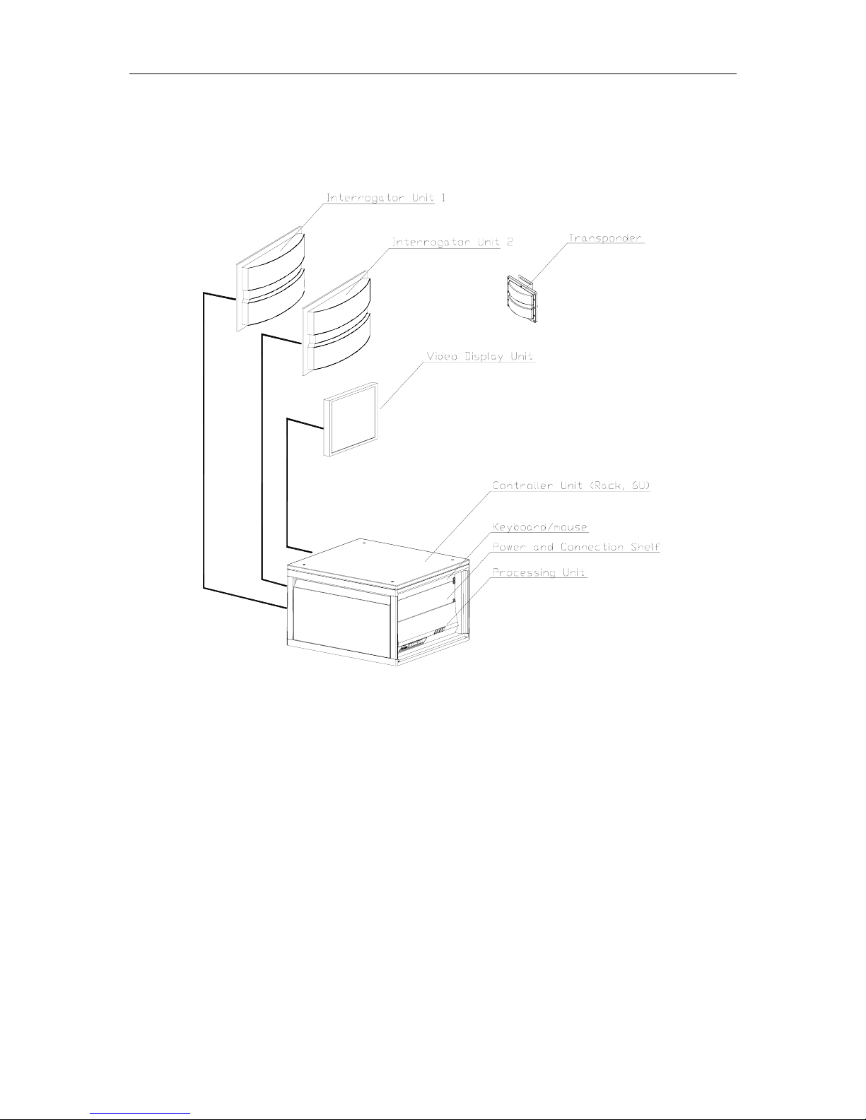
3. INSTALLATION
3.1 General information
This chapter describes a typical ship installation of the RADius system (EX approved
transponders are described in separate manuals). The standard system is supplied with the
following parts:
• A 19-inch rack (6U) (resiliently mounted)
• RADius 1000 Processing Unit (mounted in the rack)
• RADius 1000 Interrogator Unit
• RADius 500 Transponder
• VDU monitor for desktop mounting
• Keyboard with integrated mouse (1U)
• A power and connection shelf (2U) (mounted in the rack)
• Power and data cables between the Processing Unit and the Interrogator Unit
• Documentation
• Power supply - Transponder
Figure 1 RADius 1000 system, single Interrogator
RADius 1000 Installation Manual, rev. 5 Installation
10
If a dual Interrogator system is needed, another RADius 1000 Interrogator Unit is added as
shown in Figure 2.
Figure 2 RADius 1000 system, dual Interrogator
In addition to the above delivered parts, the following is needed:
• Additional cables for output lines to external equipment
• Power cable to the Transponder
For external interfaces, electrical characteristics and data formats must be decided, and the
necessary cables and connectors made available. Mains cables for the Power/ Connection
Shelf and Processing Unit are also needed.
 Loading...