

Komshine QX45, QX35 User Manual
Optical Time Domain Reflectometer
KomShine QX45/QX35
Preface
All the brands and names mentioned in this document are properties of us. This document
is subject to change without prior notice. We disclaims any liability for occasional or
secondary damages caused by errors in this document or by the use of this document or
version.
Safety Precautions
When using the product, take the following safety measures. Failure to adopt safe
operation methods or failure to observe warnings in this document may cause violation of
the safety standards for design, production, and use of the product. We disclaims any
liability for any consequence caused by violation of the preceding requirements.
Operating environment
The maximum relative humidity is 95%.
Before powering on the product
Ensure that the voltage of the power supply meets the product requirement, an
appropriate fuse is installed, and all necessary safety measures have been taken.
DO NOT use the product in an explosive environment.
DO NOT use this product in an environment with flammable gas or fume.
DO NOT remove the protective case from the product.
Operators are prohibited to remove the protective case of the product, or replace the
internal components. To remove protective case of the product, or replace the internal
components, please contact maintenance engineers of us.
Safety Symbols
This Warning symbol indicates the existence of a danger. It reminds users to pay
attention to a process, an operation method, or a similar case. Failure to
operate properly or observe related rules may cause physical injuries. Before
fully understanding and meeting the conditions indicated by this symbol, do
not proceed with the next step.
This Caution symbol indicates the existence of a danger. It reminds users to
pay attention to a process, an operation method, or a similar case. Failure
to operate properly or observe related rules may cause partial or full damages
to the product. Before fully understand and meet the conditions indicated by
this symbol, do not proceed with the next step.
This Indication symbol provides useful information for using or maintaining
the product.

1
Warning
The OTDR is a laser device. Users should always avoid direct eye contact
with the laser output. Users are strictly prohibited from using a microscope
or magnifier to observe the optical source output. The laser beam may cause
permanent damages to eyes when the energy of the laser beam is converged
on the retina.
When the OTDR is used to test an optical fiber, the working light cannot
exist on the optical fiber under test. Otherwise, the test result is
inaccurate. Even worse, the OTDR may be permanently damaged.
Precautions
Battery: The battery used by the OTDR is a rechargeable Li-ion battery. If
the OTDR has not been used for a long time, charge the battery before using
the OTDR again. If the OTDR has not been used for more than two months, charge
the battery in time to ensure that the battery power is full. DO NOT charge
the battery for more than 8 hours. It is prohibited to remove the battery unless
otherwise authorized. Keep the battery away from the fire or strong heat. DO
NOT open or damage the battery. DO NOT touch the electrolyte of the battery;
otherwise, the electrolyte may damage your eyes, skin, or clothes.
External power supply: The OTDR supports the external power supply, which
should be DC15V/1.0A.
Laser radiation: When measuring an optical fiber system, prevent direct eye
contact with the open-circuit optical fiber, optical connector, splices, or
other optical sources. Otherwise, direct contact of the eyes with the
transmitting laser will damage your eyes.
DO NOT look at the laser output port with naked eyes when the OTDR is working.
After the OTDR stops working, cover the optical port with a dust-proof cap.
DO NOT look at the unconnected end of the fiber that is being tested with
naked eyes. If possible, point the unconnected end of the fiber to an object
that cannot reflect light.

2
Contents
1 Overview ................................................................................................................................................. 4
1.1 About this Manual ..................................................................................................................... 4
1.2 Unpacking Inspection ............................................................................................................... 4
1.3 Product Introduction ................................................................................................................. 4
2 Basic Operations .................................................................................................................................. 6
2.1 Foreword ...................................................................................................................................... 6
2.2 Connectors on the OTDR ......................................................................................................... 6
2.3 Use of the Rechargeable Battery ........................................................................................... 7
2.4 Description of Function Keys .................................................................................................. 7
3 Basic Knowledge about OTDR ........................................................................................................ 9
3.1 Working Principles of OTDR ................................................................................................... 9
3.2 Basic Definition and Classification of Events ..................................................................... 9
3.2.1 Events ......................................................................................................................................... 9
3.2.2 Reflection Event....................................................................................................................... 9
3.2.3 Non-Reflection Event ........................................................................................................... 10
3.2.4 Test Event ................................................................................................................................ 10
3.3 Measurement Functions of the OTDR ................................................................................ 10
3.3.1 Measurement Contents of the OTDR ...................................................................................... 10
3.3.2 Trace Analysis of the OTDR ................................................................................................... 10
3.4 Trace Window of the OTDR ..................................................................... 错误!未定义书签。
3.4.1 Trace Pane of the OTDR ...................................................................................................... 11
3.4.2 Information Pane of the OTDR .......................................................................................... 12
3.4.2.1 Trace Measurement Parameters .................................................................................... 12
3.4.2.2 Event List .............................................................................................................................. 12
3.4.2.3 Information about the A/B Marker .............................................................................. 13
3.4.2.4 Information about the Optical fiber Link ................................................................... 14
3.4.3 Tool Bar of the OTDR ........................................................................................................... 14
3.4.3.1 Icons on the Tool Bar ....................................................................................................... 14
3.4.3.2 Parameter Setup Operations ......................................................................................... 15
3.5 Battery Charging Status ......................................................................................................... 22
4 Obtaining the Trace and Existing Trace Operations ............................................................. 23
4.1 Description of the Home Page ............................................................................................. 23
4.2 Obtaining the Trace ................................................................................................................. 23
4.2.1 Obtaining the Trace—Connecting an Optical Fiber .................................................... 24
4.2.2 Obtaining the Trace—Setting Parameters ..................................................................... 24

3
4.2.3 Obtaining the Trace—Automatic Measurement .......................................................... 24
4.2.4 Obtaining the Trace—Manual Measurement ................................................................ 25
4.2.5 Obtaining the Trace—Measurement Failure Causes ................................................... 25
4.3 Viewing the Information Pane .............................................................................................. 26
4.3.1 Switching Contents in the Information Pane ................................................................ 26
4.3.2 Viewing the Event List ......................................................................................................... 26
4.3.3 Viewing the A/B Marker Information .............................................................................. 26
4.4 Zooming in a Trace Horizontally.......................................................................................... 26
4.5 Zooming out a Trace Horizontally....................................................................................... 27
4.6 Zooming in a Trace Vertically ............................................................................................... 27
4.7 Zooming out a Trace Vertically ............................................................................................ 27
4.8 Displaying the Full Trace ........................................................................................................ 27
4.9 Saving a Trace ........................................................................................................................... 27
4.10 Viewing an Existing Trace .................................................................................................... 28
4.11 Uploading a Stored Trace .................................................................................................... 28
Appendix A Maintenance and Calibration .................................................................................. 30
Battery Maintenance and Replacement ................................................................................... 30
Cleaning of Optical Connectors .................................................................................................. 30
Calibration Requirements ............................................................................................................. 31
Appendix B Technical Specifications ............................................................................................. 32
Appendix C Warranty Information ................................................................................................. 33

4
1 Overview
1.1 About this Manual
Thank you for using the Optical Time Domain Reflectometer (OTDR) product of us. Before
using the OTDR, please read this manual carefully, especially warnings and precautions,
to prevent unnecessary physical or product damages caused by incorrect operations. This
manual covers information that is often used to operate or maintain the OTDR,
troubleshooting guide, and information for obtaining technical supports. The product has
undergone strict test and quality control processes before delivery.
1.2 Unpacking Inspection
The product is transported in compliance with the standard assembly and shipping
procedures. On receiving the OTDR, please check the product list carefully against the
packing list, and the appearance and quality of the product to find out possible physical
damages that may be caused during transportation. If the package is found damaged, please
keep the original packing materials properly and meanwhile notify the freight carrier and
the agent that supplies the product to properly resolve the problem. The product package
should contain an OTDR, an SD card, a power adapter, and an installation disk of the PC
analysis software. If any item is missing in the package, please contact the agent that
supplies the product to properly resolve the problem.
When necessary, you can contact us:
http://www.komshine.com;
KOMSHINE TECHNOLOGIES LIMITED.
1.3 Product Introduction
The OTDR launched by us is a reliable instrument used to characterize an optical fiber.
It features the compact size and simple operations, and adopts the ergonomic industrial
design and touch LCD screen. The OTDR supports the data storage function. The data can
be analyzed by using the PC software to obtain the transmission quality of an optical fiber.
In addition, the measurement results can be post-processed, archived, and printed. With
the data and images measured by the OTDR, you can evaluate characteristics of the entire
optical link. In particular, the loss feature and event distribution of the fiber under
test are visually displayed. You can use the OTDR to periodically check whether a link
meets the specification requirements. To record the transmission quality of an optical
fiber, you need to measure the optical path, total loss, and losses of all connectors.
By checking event points of optical fibers, engineers who install and maintain optical
fibers can point out faults of optical fibers, locate event points, and measure the
attenuation between event points, incurred losses, and uniformity of attenuation. In a
word, the OTDR is an indispensable tool for manufacturing, installing, or maintaining
optical fibers or cables.
The OTDR has the following characteristics:
Basic functions:
a) Measure the length of an optical fiber or cable.
b) Measure the distance between two points on an optical fiber or cable.
c) Determine the location of faults or breaks on an optical fiber or cable.
d) Describe the loss distribution trace of an optical fiber or cable.
e) Measure the attenuation coefficient of an optical fiber or cable.
f) Measure the loss between two points on an optical fiber or cable.

5
g) Measure the insertion loss of a connector on an optical fiber or cable.
h) Measure the refection of a reflection event on an optical fiber or cable.
For a specific event (changes in optical transmission characterizes due to splicing,
connector, or bending on an optical link), the OTDR can measure the following items:
a) Measure the distance, loss, and reflection of an event.
b) Measure the length and loss (dB or dB/km) of an optical section.
c) Measure the length and loss (dB) of the entire optical link.
Characteristics:
3.5' touch screen, which facilitates operations
Compact size and light weight
Graphical display of the trace data and simple operations
Storage of the trace data
USB port
PC analysis software, which is delivered with the product and can be used to back up
and archive the measurement data
AC or DC power supply
When fully charged, the battery supports more than 10 hours’ continuous working of
the OTDR.
6
2 Basic Operations
2.1 Foreword
This chapter describes the basic methods for operating the OTDR, including the keys
and frequently-used connectors. The touch screen operations have the same functions as
keypad operations. This manual provides only a brief description about the touch screen
operations. If you meet any problem when using the OTDR, please contact the technical
support engineers of us or the local agent.
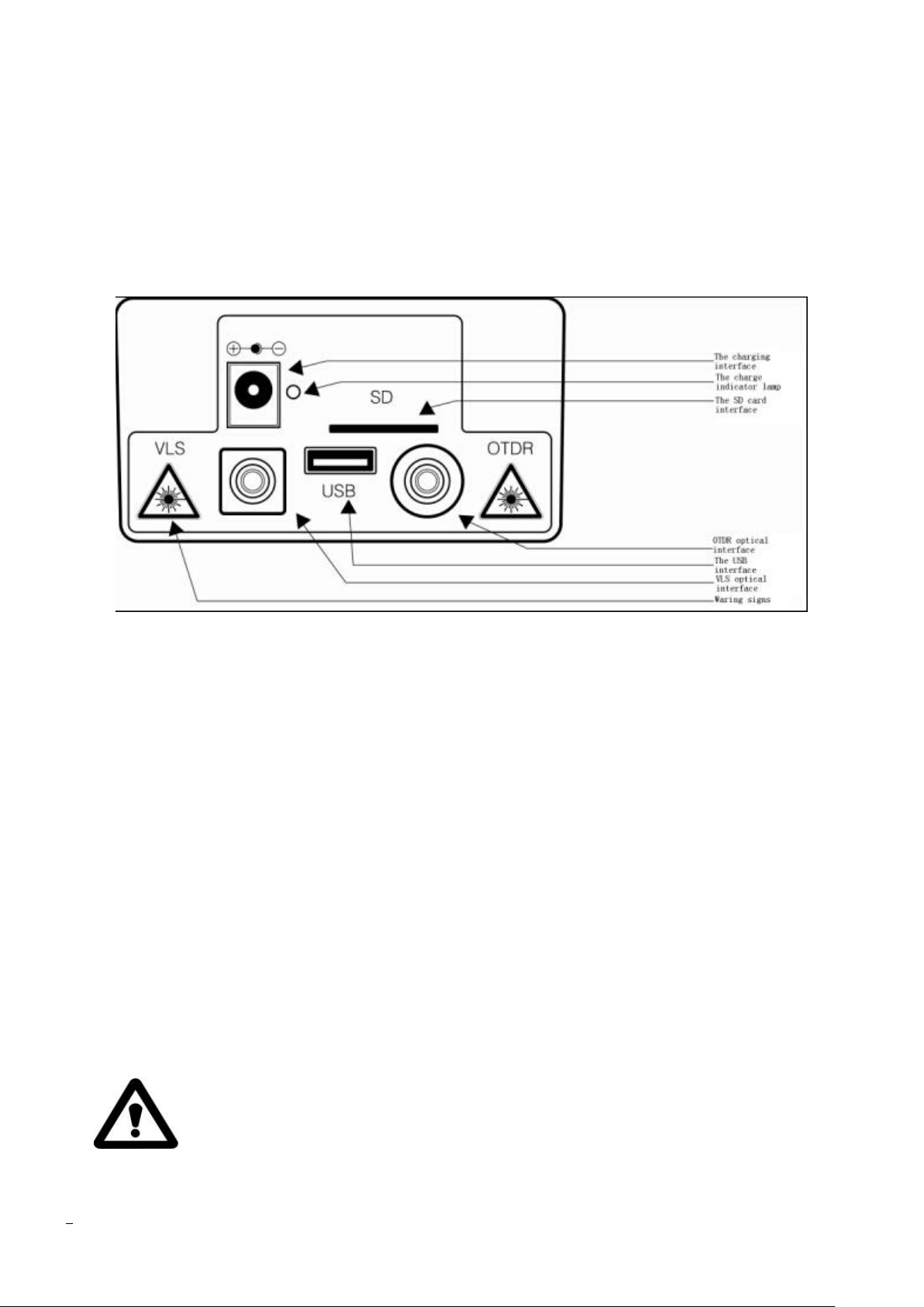
2.2 Connectors on the OTDR
Figure 2-1 Top view of the OTDR
Optical connector
All optical connectors on the OTDR are FC/UPC connectors, which are interchangeable
with SC/ST connectors.
Power connector
Requirements for the power connector: 15V DC 1.0A
Data connector
USB connector: A USB flash drive can be used to import the data to the PC data analysis
software that is delivered with the OTDR for subsequent analysis.
SD card connector: It is the data storage connector, to which an SD card is inserted.
POWER indicator
When the OTDR is powered on or being charged, the POWER indicator is on. The color
of the indicator changes with the amount of battery power. When the battery is fully
charged in the OTDR power-off state, the indicator is off.
OTDR/VLS
They are the optical connectors of the OTDR and VLS. All optical connectors are FC/UPC
connectors, which are interchangeable with SC/ST connectors.
Invisible laser radiation
DO NOT look at optical connectors or directly use an optical device to view
the optical connectors with naked eyes.

7
2.3 Use of the Rechargeable Battery
The OTDR uses an embedded Li-ion battery.
Precautions when using the OTDR
a) If the battery power is low when the OTDR is working, a low battery icon is displayed
on the LCD screen and the OTDR is automatically powered off.
b) The battery power may be low because the OTDR has not been used for a long time.
In such a case, if you attempt to power on the OTDR, the OTDR will be on for a few
seconds and then off to prevent excessive discharging of the battery. At this time,
you need to use the power adapter to charge the embedded battery immediately.
Charging the battery
a) Fast-charge the battery until the voltage reaches the preset value, and then trickle
charge the battery. The fast charging temperature of the battery ranges from 5ºC to
45ºC, whereas the trickle charging temperature ranges from 0ºC to 55ºC. The battery
is suitable for indoor use. When the charging temperature is out of the temperature
range, the battery cannot be fully charged or the battery may be damaged, which affects
the service life of the battery.
b) Fast-charge the battery for 3 hours.
c) DO NOT charge the battery for more than 8 hours.
2.4 Description of Function Keys [Enter]
On the home page, press this key to implement the function corresponding to the
key. During the menu operation, press this key so that the current operation takes
effect.
Press [Enter] together with [Shift/ ] to switch between markers A and B.
[▲] or [▼]
Major functions of these keys are as following:
Move the menu bar up or down during the menu
operation.
Select an icon for operation.
Adjust parameter values during parameter
setup.
Press [▲] or [▼] together with [Shift/ ] to
zoom in or out the comparison traces
vertically.
[◄] or [►]
Major functions of these keys are as following:
Select the parameter to be modified during
parameter setup or menu operation.
Move the marker left or right during the trace
operation.
Page up or down the help information.
Press [◄] or [►] together with [Shift/ ] to zoom in or out the comparison traces
horizontally.
[ESC]

8
Major functions of these keys are as following:
Cancel the current operation.
Exit from parameter setup.
Switch contents displayed in the information window.
Press [ESC] together with [Shift/ ] to go to the next event point.
[Shift/ ]
This key is used together with other keys to implement related functions.
[ ]
Power on or off the OTDR.
[Run/Stop]
On the home page, press this key to start a measurement. During a measurement process,
press this key to stop the measurement.
On the measurement page, press [Run/Stop] together with [Shift/ ] to implement a
real-time measurement.
[VFL]
Press and hold [VFL] for 2 seconds, and the optical connector VLS emits the continuous
red light. Press [VFL] again, and the optical connector VLS emits the pulse red light.
Press [VFL] again, and the optical connector VLS stops emitting the red light.

9
3 Basic Knowledge about OTDR
3.1 Working Principles of OTDR
Optical Time Domain Reflectometer is the full name of OTDR. OTDR is accurate
optoelectronic integrated instrument made according to back scattering that generated from
Rayleigh scattering and Fresnel reflection when lights are transmitted in the optical fiber.
It is widely used in the maintenance, construction and monitoring of cable line. It can
measure the optical fiber length, transmission attenuation of optical fiber, attenuation
of splice, and failure location, etc.
When the pulse being transmitted downwards along with the optical fiber, and some small
changes (such as changes of refractivity and discontinuity) in the material make the lights
scatter to different directions, Rayleigh scattering occurs. Partial lights are scattered
back along with the direction that opposite to pulse, therefore, it is called Rayleigh
back scattering. Back scattering light shows attenuation details that related to the length.
Information related to length is gained through time (i.e.: origin of domain of Optical
Time Domain Reflectometer). These back scattering signal indicates the attenuation
(loss/distance) degree caused by optical fiber. The curve formed is a downwards curve,
which reflects the transmission characteristics of the optical fiber.
When lights transmitted downwards along with the optical fiber encountering sudden
change of material density, Fresnel reflection occurs. Material density change may occur
at the connection or fracture parts where air gap existed. This phenomenon is used by OTDR
to accurately confirm the position of discontinuity point along with the length of optical
fiber. Compared to Rayleigh scattering, Fresnel reflection will reflect quite a lot of
lights. The power of Fresnel reflection is tens of thousands times of that of back
scattering. The reflection strength is ascertained according to the change degree of
refractivity.
3.2 Basic Definition and Classification of Events
3.2.1 Events
Events on optical fiber indicate these abnormal points that brought loss or sudden
change of reflection power beyond normal scattering of optical fiber material, including
various kinds of connection and bending, loss of flaw or fracture on the optical fiber
link.
Event points displayed on the screen is the abnormal points in the optical fiber that
led to deviation of trace, which are classified with special symbols on the trace.
Events include “reflection event” and “non-reflection event”.
3.2.2 Reflection Event
When optical pulse energy is reflected (such as on the connector), reflection event
occurs. On the trace, reflection event is shown as peak signal, as shown in Fig.3-1.

10
Fig.3-1 Reflection Event
3.2.3 Non-Reflection Event
Non-reflection event brings loss on the whole transmission link of optical fiber, but
no light reflection. On the curve, non-reflection event is shown as drop of optical power,
as shown in Fig.3-2.
Fig.3-2 Non-reflection Event
3.2.4 Test Event
OTDR sends optical pulse into the optical fiber that waited for inspection, then,
begins to accept the returned optical signal immediately, and calculate the distance of
“event” in the optical fiber. The further the event is, the longer the time for returning
back to otdr will be. The distance can be calculated according to the time when receiving
the event.
Through inspecting the curve of the reflected signal, the optical transmission
characteristics of optical fiber, connector and joint can be confirmed.
3.3 Measurement Functions of the OTDR
OTDR displays the power of the returned signal related to distance. The information
can be used to confirm the transmission quality of a fiber optic link.
3.3.1 Measurement Contents
of the OTDR
Position (distance) of event, result or fractured position of fiber optic link;
Attenuation coefficient of optical fiber in the optical fiber link;
Loss of a single event (for example, a optical connector or bending), or total losses
from end to end on the fiber optic link;
Reflection amplitude (or reflection level) of an event, such as connector.
3.3.2 Trace Analysis of the OTDR
OTDR analyzes the curve automatically. Location of the curve:
Reflection event generated from connection and mechanical connector;
Non-reflection event (usually be fusion splice);
Optical fiber bundling: through scanning the first loss event that larger than the
 Loading...