

Komptec KT-90E, KT-70SE, KT-70E User Manual

KT-70E / KT-90E / KT-70SE User Manual 24 April 2018
Page 1 of 59
KT-70E/KT-90E/KT-70SE
HIGH PRESSURE AIR COMPRESSOR
User Manual
(60Hz Version)

KT-70E / KT-90E / KT-70SE
KT-70E / KT-90E / KT-70SE User Manual Page 2 of 59 24 April 2018
Index
1. Introduction ...........................................................................................................................5
1.1. Quick Start Guide ...............................................................................................................5
1.2. Foreword ............................................................................................................................7
1.3. Documentation ...................................................................................................................7
1.4. Warranty.............................................................................................................................8
1.5. Disclaimer ..........................................................................................................................8
1.6. Required Operator Training ................................................................................................9
1.7. Information for the User .....................................................................................................9
1.8. Obligations and notes for you as an operator .......................................................................9
1.9. Customer service .............................................................................................................. 10
1.10. Serial Number ............................................................................................................... 10
1.11. Instructional and training aids. ....................................................................................... 10
1.11.1. Instruction by the operator ........................................................................................ 10
1.11.2. Examples of training topics ....................................................................................... 11
1.12. Symbols Used ................................................................................................................ 11
2. Product Description ............................................................................................................. 13
2.1. Intended Use ..................................................................................................................... 13
2.2. Construction ..................................................................................................................... 14
2.3. Optional Equipment .......................................................................................................... 14
2.3.1. Automatic shut-off. ................................................................................................... 15
2.3.2. Hour counter. ............................................................................................................ 15
2.3.3. Minimum Pressure Valve. ......................................................................................... 15
2.3.4. Automatic Condensate Drain..................................................................................... 15
2.4. Functional Description ...................................................................................................... 16
2.5. Pneumatic Air Flow .......................................................................................................... 17
2.5.1. Intermediate Stage Condensate Collector and Drain. ................................................. 17
2.5.2. Final Condensate Collector, Drain and Filter. ............................................................ 17
3. General safety ...................................................................................................................... 18
3.1. Obligation of diligence ..................................................................................................... 18
3.2. Basic safety measures ....................................................................................................... 18
3.2.1. Principle; Intended Use ............................................................................................. 18
3.2.2. Responsibility ........................................................................................................... 18
3.2.3. Personnel selection and qualification; fundamental obligations ................................. 19
3.2.4. Safety instructions for certain operating phases ......................................................... 19

KT-70E / KT-90E / KT-70SE User Manual Page 3 of 59 24 April 2018
3.2.5. Notes on special types of hazard................................................................................ 21
4. EG-Konformitätserklärung ................................................................................................... 23
5. Technical Specifications ...................................................................................................... 24
5.1. Compressor System .......................................................................................................... 24
5.2. Compressor Block ............................................................................................................ 24
5.3. compressor oil .................................................................................................................. 24
5.4. Connections ...................................................................................................................... 24
5.5. Pneumatic Flow Diagram – Base Configuration ................................................................ 26
6. Transport and Installation ..................................................................................................... 27
6.1. Transport .......................................................................................................................... 27
6.1.1. Transport to the Site .................................................................................................. 27
6.2. Installation ....................................................................................................................... 27
6.2.1. Conditions for Set-up ................................................................................................ 27
6.3. Placement ......................................................................................................................... 28
7. Start-up ................................................................................................................................ 29
7.1. Power ............................................................................................................................... 29
7.2. Checks before initial Start-up ............................................................................................ 29
8. Operation ............................................................................................................................. 30
8.1. Description of the controls ................................................................................................ 30
8.1.1. Compressor ............................................................................................................... 30
8.1.2. Filling Hose .............................................................................................................. 31
8.2. Adjusting and Setting........................................................................................................ 32
8.2.1. Operation .................................................................................................................. 32
8.2.1.1. Starting the Motor................................................................................................. 32
8.2.1.2. pressure buildup ................................................................................................... 33
8.2.1.3. To Fill the pressure cylinder. ................................................................................ 33
8.2.1.4. Condensate Drain ................................................................................................. 34
8.2.1.5. Turning off ........................................................................................................... 34
8.2.1.6. Complete the Filling process ................................................................................. 35
8.3. Filter ................................................................................................................................. 35
8.3.1. Breathing Air Filter ....................................................................................................... 35
8.3.2. Non-Breathing Air Filter ............................................................................................... 35
8.4. Extended Storage .............................................................................................................. 36
8.4.1. Waste Disposal ......................................................................................................... 36
9. Troubleshooting ................................................................................................................... 37
9.1. Tabular overview of possible malfunctions and suggestions to help eliminate the fault. .... 37
9.1.1. List of Faults ............................................................................................................. 37

KT-70E / KT-90E / KT-70SE User Manual Page 4 of 59 24 April 2018
10. Maintenance ........................................................................................................................ 39
10.1. Consumable Parts .......................................................................................................... 39
10.2. Maintenance Plan .......................................................................................................... 40
10.3. Filter changing log. Please top off the crankcase oil each time the air filter is changed. . 42
10.4. Maintenance Work ........................................................................................................ 43
10.4.1. Checking the Oil Level ............................................................................................. 43
10.4.2. Filter Change. Please top off the crankcase oil each time the air filter is changed. ... 44
10.4.3. Oil Change ............................................................................................................... 45
10.4.4. Final pressure gauge check ....................................................................................... 46
10.4.5. Check final pressure safety valve .............................................................................. 46
10.4.6. Other Maintenance Notes.......................................................................................... 46
11. Break-out Drawings ............................................................................................................. 47
Figure A. Exploded View ............................................................................................................. 47
Figure B. Crankshaft with Piston Rods ......................................................................................... 48
Figure C. First Stage Cylinder ...................................................................................................... 49
Figure D. Second Stage Cylinder .................................................................................................. 50
Figure E. Third Stage Cylinder ..................................................................................................... 51
Figure F. Oil filler tube and housing pressure equalization ............................................................ 52
Figure G. Filter Housing ............................................................................................................... 53
Figure H. Casing ........................................................................................................................... 54

KT-70E / KT-90E / KT-70SE User Manual Page 5 of 59 24 April 2018
1. Introduction
1.1. Quick Start Guide
Note this manual is for the US type configuration with 115V or 230V 60Hz supplies. For
230V 50Hz units, please refer to the appropriate manual.
SAFETY NOTICE!
• Read the User Manual before using the compressor
• Disconnect the power and depressurize the filter housing before removing the housing
• The compressor should not be run continuously for more than 45 minutes after which it needs
15 minutes rest.
Prior to operation
• Verify the plug meets local codes, and that the electrical outlet is able to supply the required
current at the required voltage.
• Place the compressor on a flat stable surface or solid surface. Keep a safe distance from wall.
A pitch of up to 20° from Horizontal is permissible.
• Check the oil level is at the mid point of the dipstick or higher, and if necessary top off the
oil.
• For the first time it is operated, run the compressor for 5 minutes with the condensate drains
open.
• Connect the pressure vessel.
• Close the output fill valve if present, or the valve on the pressure vessel.
Running the compressor
• Turn on Compressor.
• Residual high pressure within the compressor may prevent the motor (either gas or electric)
from turning over. If so, open condensate drain valves or output fill valve and vent some of
the residual pressure.
• For the first time it is operated or after an extended period of non-operation, run the compres-
sor for 5 minutes with the condensate drains or output open.
• Insure both condensate screws are closed
• Once output pressure rises to1500 psi (100 bar), slowly open the fill valve.
• Drain the condensate every 15 to 25 minutes while operating by opening the final and inter-
mediate drain screws briefly until the accumulated condensate is released.
• Supervise compressor during filling.
Finish filling
• Turn off the compressor
• Close the filling valve
• Slowly open the bleed screws on the filling hose (if so configured) until the pressure within
the fill hose is released, then the pressure vessel can be removed.
• Open final Condensate screw slowly, capture condensate and dispose of accordingly. Repeat
for intermediate Condensate Drain.
• If the compressor will be out of use for an extended period, run the compressor with both
condensate fill valves open for a minimum of 1 minute.

KT-70E / KT-90E / KT-70SE User Manual Page 6 of 59 24 April 2018
Maintenance
• Filter cartridges should be changed on the interval described in 8.3, or once per year.
• Top off the crankcase oil each time the filter is changed.
• Once a year or every 500 operating hours change the crankcase oil.
• Check the oil level before each use.
ATTENTION in case of malfunction, depressurize compressor and remove power

KT-70E / KT-90E / KT-70SE User Manual Page 7 of 59 24 April 2018
1.2. Foreword
Dear Customer,
Thank you for choosing the KT-70E / KT-90E / KT-70SE
This manual is an aid to successful and safe operation of the compressor.
These materials are only for information purposes. Changes may be made
without prior notice. Please refer to the manual for compliance to regulations,
for accident prevention and environmental protection.
Keep this manual available where the compressor is in use. Any person who
is authorized to work on the compressor must have read the operating instructions.
The compressor has been built according to state of the art and recognized
safety regulations. Nevertheless, it can be hazardous.
Read this manual before using the compressor is in operation. It helps you:
• Prevent risks to the operator,
• Become familiar with the compressor,
• To avoid interference due to improper operation,
• To increase the life of the compressor,
• To avoid repair costs and downtime,
• To effectively use the compressor.
1.3. Documentation
To avoid operating errors and to ensure trouble-free operation of the compressor, the user guide the operator must always be accessible.
All documents are protected within the meaning of the copyright law.
Violations are an offense and liable to compensation. All rights to exercise
intellectual property rights We reserve the right.

KT-70E / KT-90E / KT-70SE User Manual Page 8 of 59 24 April 2018
1.4. Warranty
We warranty to the original owner of the KT-70E / KT-90E purchased from Komptec as
new will be free from manufacturing defects in materials and workmanship under normal
use within a period of (1) one year from date of purchase for an end user, or (90) ninety
days for a commercial user, provided it is operated and maintained according to instructions and the user manual. Contact Komptec for the warranty policy inside the European
Union..
Our obligation under this warranty is limited, at our election expressly to the replacement
or repair of such parts from the manufacturer, or at a service center designated by us, who
have been found by the audit to be defective.
DISCLAIMERS:
This warranty does not cover damage due to negligence or improper use, including faulty
repairs by others and failure to implement reasonable and necessary maintenance. We
are not liable for any special, indirect, incidental or consequential damages of any kind,
including wage and transport costs in connection with the repair or replacement of defective parts.
NO WARRANTY, ORAL OR WRITTEN, EXPRESED OR IMPLIED, OTHER THAN
THE ABOVE WARRANTY IS MADE WITH REGARD TO THIS KOMPTEC PRODUCT. KOMTEC DISCLAIMS ANY IMPLIED WARRANTY OF MERCHATABILITY OR FITNESS FOR A PARTICUALR USE OR PURPOSE, AND ALL OTHER
WARRANTIES. IN NO EVENT SHALL KOMPTEC BE LIABLE FOR ANY INCIDENTAL, SPECIAL, CONSEQUENTIAL OR PUNITIVE DAMAGES OR FOR ANY
COSTS, ATTORNEY FEES, EXPENSES, LOSSES OR DELAYS ALLEGED TO BE
AS A CONSEQUENCE OF ANY DAMAGE TO, FAILURE OF, OR DEFECT IN ANY
PRODUCT INCLUDING, BUT NOT LIMITED TO, ANY CLAIMS FOR LOSS OF
PROFITS.
1.5. Disclaimer
Based upon the Law on Technical Equipment (Product Safety Act) of 6 January 2004 (I,
p. 2, over p. 219), as amended on 8 November 2011 (I, p. 2178, calc. 2012 I, p 131)) the
following applies:
• Operation of the KT-70E / KT-90E / KT-70SE requires expertise and training,
and is limited to applications defined by Komptec in this user manual.
• In the event of improper maintenance (servicing) or of ignoring the operating in-
structions, the owner assumes full responsibility for the functioning of the appliance.
• For safety reasons, the device should be maintained and tested by an authorized
agent annually.

KT-70E / KT-90E / KT-70SE User Manual Page 9 of 59 24 April 2018
• The device must be serviced by experts. During maintenance (service) only orig-
inal spare parts may be used. The maintenance must be recorded.
• In the event of damage caused by not complying with the above listed points,
Komptec GmbH is not liable. The warranty and liability claims or general terms
and conditions of Komptec GmbH are not changed by the guidelines listed above.
1.6. Required Operator Training
This manual must be read carefully:
• all compressor operators’ / maintenance personnel must read this entire manual with
due care and attention and observe the instructions/information contained herein.
• the operator must possess the required training for operation of the compressor and
read the manual.
1.7. Information for the User
The instruction manual must be read and used as follows:
• read this manual carefully, treat it as an essential part of the compressor;
• the instruction manual must be kept where it can readily be consulted by compressor
operators and maintenance staff
• keep the manual for the working life of the compressor
• make sure updates are incorporated in the manual
• make sure the manual is given to other users or subsequent owners in the event of
resale
• keep the manual in good condition and ensure its contents remain undamaged
• do not remove, tear or re-write any part of the manual for any reason
• keep the manual protected from dampness and heat
• if the manual is lost or partially damaged and its contents cannot be read, please re-
quest a copy from the manufacturer.
1.8. Obligations and notes for you as an operator
The instruction manual is an integral part of the compressor. The operator shall ensure
that this manual is always available on the compressor and that the operator assumes the
guidelines note.
In order to protect personnel against health hazard or other safety hazards, the operator is
obliged to inform his/her self on the safe and proper operation, maintenance and the
proper operation of the compressor.
The operator must arrange for the execution of a test run with testing of all safety equipment in order to satisfy itself of the operational safety of the compressor and to be able to
properly and safely operating on the ability of the staff, the operation after completing the
installation and before using the compressor.
KT-70E / KT-90E / KT-70SE User Manual Page 10 of 59 24 April 2018
The compressor has been built according to the prior art and the recognized safety regulations. As an operator, you are obliged to adapt the compressor to the applicable current
safety regulations.
It should be born in mind that the User Manual can never replace proper experience; some
maintenance jobs are particularly difficult and in this regard the manual only offers general guidelines on the most important tasks, which must be carried out by personnel with
proper training (e.g. acquired during training courses run by the manufacturer).
1.9. Customer service
For technical information about Komptec’s products and their systematic application,
please contact customer service.
Should you have any questions about our products, please call our customer service department.
1.10. Serial Number
Please include the serial number from the nameplate on any inquiries. Specifying this
data ensures that you receive the correct information or the required spare parts.
1.11. Instructional and training aids.
1.11.1. Instruction by the operator
Any failure to comply with the safety instructions in this manual or on
the compressor can result in injury or death.
Read the KOMPTEC Instruction Manual. All compressor operators’ / maintenance personnel must read this entire manual with due care and attention and
observe the instructions/ information contained herein.- the operator must
possess the required training for operation of the compressor and that he/she
has read the manual.
In addition to the operating instructions, applicable statutory and other regulations for accident prevention and environmental protection and basic health
and safety requirements must be observed.
Such requirements may also include the handling of hazardous substances,
which affect provision / wearing of personal protective equipment.
Consider:
Operation of this compressor poses danger to life and limb when operated by
untrained personnel, or when operated when improperly mounted, maintained
or used.
The training of the operating personnel must be repeated every year!

KT-70E / KT-90E / KT-70SE User Manual Page 11 of 59 24 April 2018
Operator seminars, and art workshops are offered regularly by the manufacturer.
The following are examples of topics for training as well as a form for confirmation of instruction.
1.11.2. Examples of training topics
1. For safety
• Accident prevention regulations
• General legislation
• General safety
• Measures in case of emergency
• Personal protective equipment
• Safety instructions for the operation of the plant
• Dealing with the safety devices of the system
• Safety devices in the vicinity of the plant
• Meaning of symbols and signs
• ________________________________
• ________________________________
2. To operate the plant
• Use the operating elements
• Explanation of the operating instructions for the operating person-
nel
• Special experience of the operator in handling the compressor
• The use of input materials, tools and auxiliary equipment
• ________________________________
• ________________________________
3. Servicing and maintenance requirements
• Regulative handling cleaning agents and lubricants
• Special experience of the operator for maintenance, servicing, cleaning
and maintenance of plant
• ________________________________
• ________________________________
1.12. Symbols Used
In the manual, the following terms and symbols for particularly important
information are used:
information
Special information regarding the economical use of the machine
i

KT-70E / KT-90E / KT-70SE User Manual Page 12 of 59 24 April 2018
Warning
Particular specifications or instructions and prohibitions to prevent damage
Danger
Specifications or instructions and prohibitions to prevent personal injury or
substantial property damage
Mark
for performing an action by the operator
Enumeration
Hint
Useful hints and tips for the operator
●
F
KT-70E / KT-90E / KT-70SE User Manual Page 13 of 59 24 April 2018
2. Product Description
2.1. Intended Use
The compressor is exclusively for compressing air at an operating pressure of 4500 psi
with a maximum pressure of plus 10%. The compressor block is designed for intermittent
operation. The maximum duration must not exceed 45 minutes. After a rest time of 15
minutes is necessary. This represents a total investment of 4 Nm. Any other use or extended use is considered improper. The manufacturer is not liable for any resulting damage. The risk is borne solely by the user.
It is expressly prohibited to draw gases other than air. Operation in a Nitrox environment
up to 36% oxygen concentration is permitted.
Intended use also includes observing the operating instructions and compliance with the
inspection and maintenance conditions.
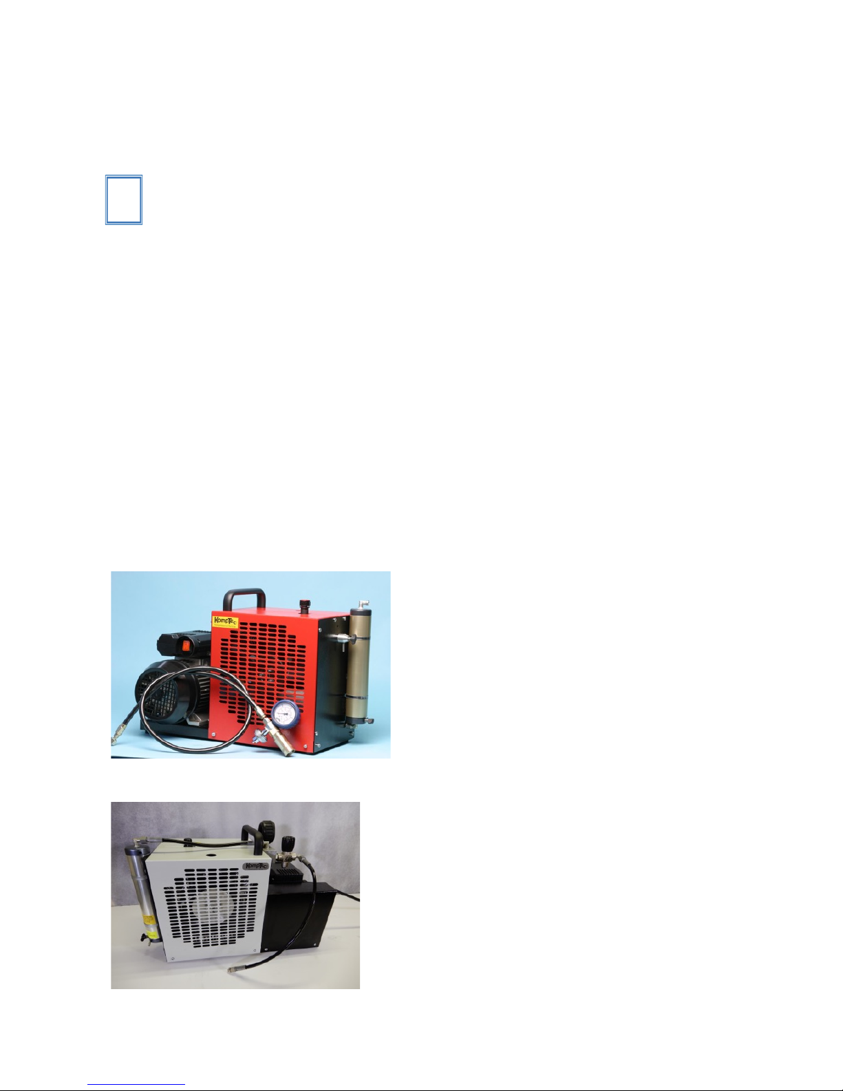
The 2.5 CFM KT-70E and KT-70SE are tailored to the specific requirements of filling
air tanks of up to 20L. The 3.2 CFM KT-90E is suited for filling air tanks of up to 45L.
Their construction has been designed for this purpose.
The KT-70E and KT-90E are targeted at SCUBA and other markets using DIN 200 or
DIN 300 couplers. The KT-70SE “Shooter’s Edition” is intended for Air Gunners and
Paintball enthusiasts using a foster style Quick Disconnect on their air cylinders.
Figure 1. KT-90E
Figure 2. KT-70SE
i
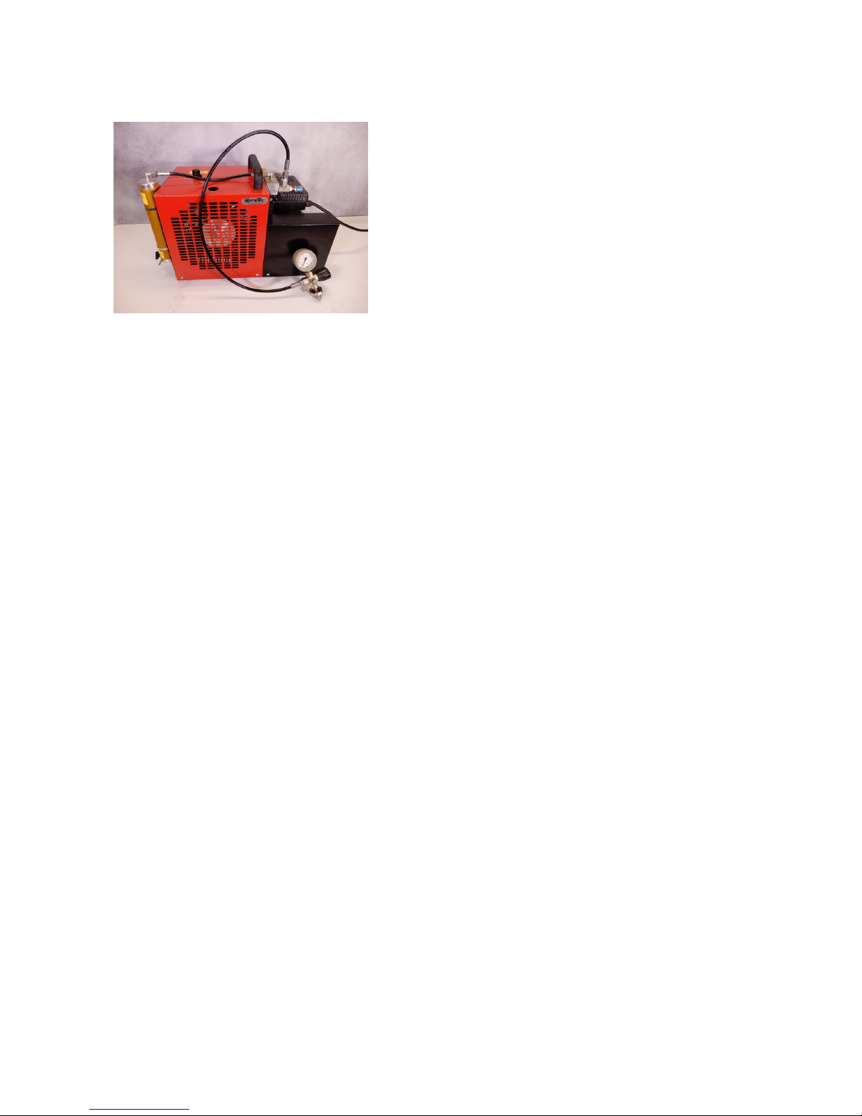
KT-70E / KT-90E / KT-70SE User Manual Page 14 of 59 24 April 2018
Figure 3. KT-90E Configuration 1 and 2
2.2. Construction
The main structure of the compressor is made up of the following components:
Standard equipment high pressure compressor:
• housing
• drive
• Compressor block
• filter unit
• filling unit
Standard accessories:
• Filling hose for 4500 psi (300 bar DIN connector) or 3000 psi (200 bar DIN connector)
for “E” series compressors, or Quick Disconnect for “SE” series.
• an intake filter (in housing)
• a high-pressure compressed air filter with filter cartridge
• On-off switch
2.3. Optional Equipment
The KT-70E and KT-90E are offered as one of three configurations, based on the intended
use, and the user’s budget.
• Base Configuration: (Base Option) The base configuration groups together the pres-
sure gauge, safety valve, and DIN connector on the end of the fill hose. After filling,
pressure is relieved in the fill hose as part of the process of draining the condensate,
by opening the final condensate drain.
• Configuration 1 (C1 Option): C1 adds a Minimum Pressure Valve (also called a Pri-
ority Valve), as well as a fill valve and bleed valve to the end of the fill hose, and
moves the safety valve to the Compressor housing.

KT-70E / KT-90E / KT-70SE User Manual Page 15 of 59 24 April 2018
• Configuration 2 (C2 Option): C2 builds on the C1 configuration, and adds the Auto-
matic Shut-Off and Hour Counter.
The KT-70SE is configured with a fill valve with bleed, and a fill hose with a Quick Disconnect coupling. The Automatic Shut-Off and Hour Counter are optional on the KT-70SE
2.3.1. Automatic shut-off.
If configured with the automatic shut-off, the compressor will fill the target cylinder to
the maximum rated pressure of the compressor, then turn off the motor.
2.3.2. Hour counter.
If configured with the Hour counter, the operating hours will be displayed on the hour
counter, mounted on top of the electrical motor.
2.3.3. Minimum Pressure Valve.
If configured with the Minimum Pressure Valve, air will not flow out of the filter until
the minimum pressure is achieved (150 bar, or 2200 psi, minimum), and when a large
cylinder is being filled, the pressure within the filter will be maintained at the minimum
pressure or above. (Not available with KT-70SE)
2.3.4. Automatic Condensate Drain.
If configured, the Automatic Condensate Drain (ACD) will bleed off the condensate
into a separate container on a defined interval.

KT-70E / KT-90E / KT-70SE User Manual Page 16 of 59 24 April 2018
2.4. Functional Description
Standard Equipment
The housing consists of the
base plate with the cover.
Most components are
mounted on the base plate.
The drive consists of a 230V
motor, a pulley and drive
belt. See 115V photo below
The drive can also be a gas
motor with a V-belt pulley
and V-belts.
The compressor block consists of 3 compressor stages.
The filter unit consists of a
high-definition filter and the
condensate drain.
The intake filter is incorporated in the housing for the
KT-70E / KT-90E.
In the gasoline version of the
KT-70E / KT-90E, a snorkel
may be fitted.
The intake filter for the gasoline version of the compressor must be mounted at least
1 m above the compressor.
The filling unit (base configuration) consists of: pressure
gauge, safety valve and fill
port. See optional filling
unit description in sec. 8.1.2
KT-70E / KT-90E / KT-70SE User Manual Page 17 of 59 24 April 2018
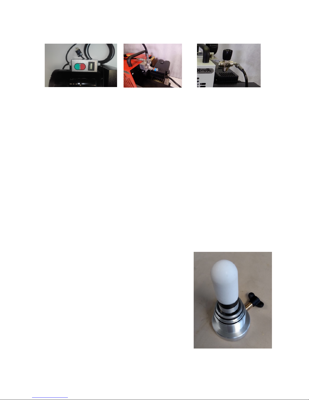
KT-70E 115V On/Off
switch and Hour Counter
configuration
Fill block for Configuration 1
or 2, showing attachment
point for fill hose, safety
valve, MPV, and Auto ShutOff sensor
Fill valve for KT-70SE with
fill whip attached
2.5. Pneumatic Air Flow
The compressor has two elements where moisture and / or condensate is removed.
2.5.1. Intermediate Stage Condensate Collector and Drain.
A condensate drain is positioned after the first stage intercooler, prior to the intake for
the second stage.
2.5.2. Final Condensate Collector, Drain and Filter.
The filter housing contains both the Final Condensate Collector as well as the air filter.
One key element used in the condensate collector is the sintered filter. A conical synthetic sintered filter is installed in the base of the filter housing. Air enters the housing
after the 3rd stage and the aftercooler, and flows through the sintered filter where oil and
moisture condense on the interior surface of the sintered filter, and fall to the base of the
condensate collector. The moisture and oil that is captured here are contaminants that
need not be captured by the filter, extending its effective service life.
An additional benefit of using the sintered filter
prior to the filter cartridge is that the air that exits
the sintered filter and flows thru the molecular sieve
filter has an even velocity across the surface of the
filter as it enters the filter. This avoids the creation
of a high velocity path thru the filter material. Constant air velocity permits optimum effectiveness of
and utilization of the molecular sieve material

KT-70E / KT-90E / KT-70SE User Manual Page 18 of 59 24 April 2018
3. General safety
3.1. Obligation of diligence
To ensure maximum working efficiency, Komptec has constructed the compressor with
carefully selected components and materials. The compressor is tested prior to delivery.
Continued compressor efficiency over time will also depend on proper use and maintenance as per the instructions contained in this manual.
However, this safety can only be achieved in operational practice if all necessary
measures are taken. It is the obligation of diligence of the operator to plan these measures
and to monitor their implementation.
The operator must in particular ensure that
- the compressor is only used as intended (see chapter description)
- the compressor is operated only in perfect working condition and safety equipment
in particular is checked regularly for proper functioning,
- required personal protective equipment for the operating, maintenance and repair
personnel are available and are in use,
- the user manual is always in a legible condition, is complete and is available at the
site of the compressor,
- only sufficiently qualified and authorized personnel operate the compressor and per-
form maintenance and repairs,
- the personnel are regularly instructed in all applicable questions regarding occupa-
tional safety and environmental protection and knows the operating instructions and
particularly the safety instructions contained therein,
- safety instructions and warnings are all mounted on the compressor are not removed
and remain legible.
3.2. Basic safety measures
3.2.1. Principle; Intended Use
The compressor has been built according to the prior art and the recognized safety regulations. Nevertheless, danger to life and limb to the user and to third parties, or damage
to the compressor or other tangible assets can arise. The following table shows how this
manual is organized and when and what the individual sections are needed.
The compressor must be maintained in good working condition. In particular, faults that
can impair safety must be rectified immediately!
The compressor is intended exclusively for filling compressed air cylinders. Any other
use or extended use is considered improper. The manufacturer is not liable for any resulting damage. The risk is borne solely by the user.
Intended use also includes complying with the operating instructions and compliance with
the inspection and maintenance conditions.
3.2.2. Responsibility
The operating instructions must remain accessible and kept at hand at the compressor!
 Loading...