

Page 1
GRAPADORA NEUMÁTICA
SET PISTOLA SPARAPUNTI AD ARIA COMPRESSA
gRapaDoRa neUmáTiCa
Instrucciones de utilización y de seguridad
aiR STapLeR SeT
Operation and Safety Notes
SeT piSToLa SpaRapUnTi
aD aRia CompReSSa
Indicazioni per l’uso e per la sicurezza
DRUCKLUFT-TaCKeR-SeT
Bedienungs- und Sicherheitshinweise
Page 2
Antes de empezar a leer abra las dos páginas que contienen las imágenes y, en seguida, familiarícese
con todas las funciones del dispositivo.
Prima di leggere aprire le due pagine con le immagini e prendere confidenza con le diverse funzioni
dell’apparecchio.
Before reading, unfold both pages containing illustrations and familiarise yourself with all functions of the
device.
Klappen Sie vor dem Lesen die beiden Seiten mit den Abbildungen aus und machen Sie sich anschließend
mit allen Funktionen des Gerätes vertraut.
ES Instrucciones de utilización y de seguridad Página 5
IT / MT Indicazioni per l’uso e per la sicurezza Pagina 13
GB / MT Operation and Safety Notes Page 21
DE / AT / CH Bedienungs- und Sicherheitshinweise Seite 29
Page 3
10
1 2 3 4
9
8
A
7
56
Page 4
B
C
D
Page 5

Introducción
Uso adecuado ..............................................................................................................Página 6
Equipamiento.................................................................................................................Página 6
Volumen de suministro ..................................................................................................Página 6
Datos técnicos ...............................................................................................................Página 6
Seguridad de la remachadora
Seguridad laboral .........................................................................................................Página 7
Indicaciones de seguridad adicionales para la grapadora neumática ....................Página 8
Accesorios originales y adicionales ............................................................................Página 9
Puesta en funcionamiento
Conexión de la fuente de aire comprimido ................................................................Página 9
Llenado del cargador ...................................................................................................Página 9
Manejo ........................................................................................................................Página 9
Índice
Limpieza y mantenimiento
Mantenimiento ..............................................................................................................Página 10
Limpieza .........................................................................................................................Página 11
Asistencia técnica ...............................................................................................Página 11
Garantía .....................................................................................................................Página 11
Eliminación ...............................................................................................................Página 11
Declaración de conformidad / Fabricante......................................Página 12
5 ES
Page 6
Introducción
En estas instrucciones de uso / en el aparato se utilizan los siguientes pictogramas:
¡Lea las instrucciones de uso!
¡Siga las indicaciones de prevención
y seguridad!
Utilice gafas de protección y
un protector de oídos
Grapadora neumática
Introducción
Familiarícese con las funciones de la
remachadora antes de ponerla en fun-
cionamiento por primera vez e infórmese
sobre su uso adecuado. Para ello, lea las siguientes
instrucciones de uso. Conserve bien estas instrucciones. En caso de transferir la remachadora a terceros, entrégueles también toda la documentación.
Q
Uso adecuado
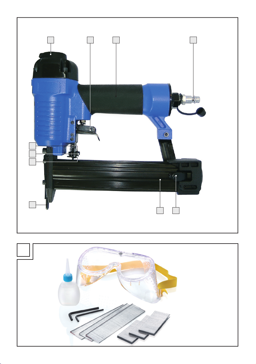
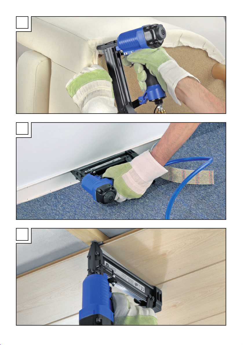
Este aparato ha sido diseñado para trabajos de
montaje y reparación (véase fig. B, C, D). Cualquier otro uso o la modificación del aparato se
consideran inadecuados y conllevan considerables
peligros de accidente. No asumiremos responsabilidad por los daños ocasionados debido a un uso
distinto del adecuado. El aparato está destinado
solamente para fines particulares.
Q
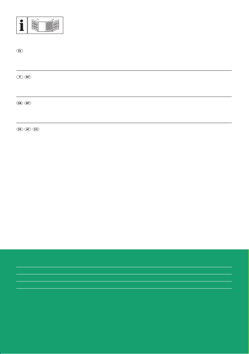
Equipamiento
1
Embellecedor deflector de aire (giratorio)
2
Disparador
3
Mango
4
Racor para la conexión de aire ¼“ AG
5
Palanca del cargador
6
Cargador
7
Seguro de disparo
8
Tope inferior
6 ES
Mantenga a los niños alejados
de la grapadora.
Seguro de disparo
¡Evacue el embalaje y el aparato
de forma respetuosa con el medio
ambiente!
9
Tornillo moleteado
10
Tope superior
Q
Volumen de suministro
1 x grapadora neumática
1 x maletín de transporte
1 x aceite especial para herramientas neumáticas
1 x racor para la conexión de aire, ¼‘‘ AG
(preinstalado)
1 x paquete de clavos, 1000 uds.
1 x paquete de grapas, 1000 uds.
1 x gafas de seguridad
1 x llave Allen, 3 mm
1 x llave Allen, 4 mm
1 x manual de instrucciones
Q
Datos técnicos
Presión de trabajo: máx. 7 bar
Capacidad de carga: 100 uds.
Longitud del clavo: 15 - 32 mm
Longitud de la grapa: 16 - 32 mm
Anchura de la grapa: 5,7 mm
Diámetro recomendado
del tubo: Ø 9 mm
Calidad del aire comprimido: limpio, con neblina
de aceite y sin
condensación
Información de ruido y vibraciones:
Valor de medición calculado según
EN 12549:1999, EN ISO 4871. El nivel de
presión acústica A evaluado del aparato es
Page 7
Introducción / Seguridad de la remachadora
normalmente de 85,7 dB (A). Tolerancia K = 3 dB.
El nivel de ruido durante el trabajo puede superar
los 98,7 dB (A).
Estos valores son parámetros característicos referidos al aparato y no reproducen el desarrollo de
ruido en el lugar de aplicación. El desarrollo de
ruido en el lugar de aplicación depende p. ej. del
entorno de trabajo, de la pieza, del soporte para
la pieza, del número de procesos de remache.
Según sea la situación en el puesto de trabajo y la
configuración de la pieza de trabajo, deberán ser
tomadas en caso necesario medidas individuales
de insonorización, como p. ej. colocar las piezas
de trabajo sobre bases amortiguadoras de sonido,
prevenir vibraciones de las piezas de trabajo inmovilizándolas o cubriéndolas, ajustar la sobrepresión de aire al mínimo necesario para el proceso
de trabajo, etc. En casos especiales será necesario
el uso de un protector auditivo personal.
¡Es necesario llevar
protección auditiva!
Valores totales de vibraciones según
EN ISO 8662-11:
Valores totales de vibraciones a
Tolerancia K = 1,5 m / s
Choques mecánicos (vibración)
Para esta remachadora se ha hallado el parámetro
el vibración según ISO 8662-11:1999 „Herramientas eléctricas portátiles, Medida de vibraciones mecánicas en el mango, Remachadoras“ (vea
„Datos técnicos“). El valor es un parámetro característico referido al aparato y no representa el efecto sobre el sistema mano-brazo al utilizar el aparato. El efecto sobre el sistema mano-brazo al utilizar
el aparato depende p. ej. de la fuerza de sujeción,
la fuerza de apriete, la dirección de avance, de la
presión del aire ajustada, de la pieza de trabajo,
del soporte de la pieza.
2
= 2,0 m / s
h,D
2
Seguridad de la
remachadora
¡ADVERTENCIA!
e indicaciones de seguridad. La inobservan-
cia de las indicaciones de seguridad y de las
advertencias podría causar lesiones graves y / o
daños materiales.
CONSERVE TODAS LAS INDICACIONES DE
SEGURIDAD Y ADVERTENCIAS POR SI
NECESITA CONSULTARLAS MÁS ADELANTE.
J Antes de iniciar cualquier trabajo ve-
rifique siempre el perfecto funciona-
miento de los dispositivos de seguri-
dad y de disparo así como el asiento
firme de todos los tornillos y tuercas.
J No efectúe ningún tipo de manipula-
ción en la remachadora contrario a
las prescripciones.
J No desmonte o bloquee ninguna
pieza de la remachadora, como p. ej.
un seguro de disparo.
J No efectúe ninguna „reparación de
emergencia“ con medios inadecua
J La remachadora deberá ser objeto
de trabajos de mantenimiento de
forma regular y experta según las
instrucciones del fabricante.
J Evite cualquier devaloración y daño
del aparato, p. ej. por:
- estampados o grabados,
- medidas de ampliación no permitidas por el fabricante
- conducción por plantillas hechas de
materiales duros, p. ej. acero,
- dejar caer o arrastrar por el suelo,
- manejo como martillo,
- cualquier uso de actos violentos.
Q
Seguridad laboral
Lea las advertencias
dos.
J No dirigir nunca una remachadora
lista para el servicio directamente a
uno mismo o a otras personas.
7 ES
Page 8
Seguridad de la remachadora
J Durante el trabajo, mantener la
grapadora de forma que no pueda
causar daños ni a la cabeza ni al
cuerpo en caso que se produzca un
retroceso ocasionado por una anomalía en el suministro eléctrico o
porque la pieza que se desea grapar
tenga puntos duros.
J No activar nunca la remachadora sin
apoyarla en una pieza a grapar. De
este modo, se evitará el riesgo ocasionado al
dispararse un remache o sobrecargarse el
aparato.
J Para transportar la remachadora, es
preciso desconectarla de la red de
aire comprimido, en especial cuando
se estén utilizando escaleras o la
posición corporal sea inadecuada.
J Para transportar la remachadora
en el lugar de trabajo, es preciso
llevarla por la empuñadura estando
el disparador desactivado.
J Tenga en cuenta las condiciones en el
lugar de trabajo. Los remaches podrían
atravesar piezas finas o resbalar al trabajar en
esquinas y cantos pudiendo dañar a las personas presentes.
J Para protegerse es impres-
cindible utilizar equipos de
protección corporal adecuados,
como, p. ej., protectores visuales y
auditivos. Si lleva equipo de protección per-
sonal, como mascarilla antipolvo, zapatos de
seguridad antideslizantes, casco de seguridad
o protección auditiva, en función del tipo y la
utilización de la remachadora, reducirá el
riesgo de lesiones.
Indicaciones de seguridad
adicionales para la
grapadora neumática
¡ADVERTENCIA!
LESIONES! Nunca sobrepase la presión de
trabajo máxima permitida de 7 bar. Para ajustar la presión de trabajo utilice un dispositivo
reductor de presión.
¡PELIGRO DE
¡ADVERTENCIA!
LESIONES! Nunca utilice oxígeno u otros
gases inflamables como fuentes de energía.
¡PELIGRO DE
J Mantenga el lugar de trabajo limpio
y bien iluminado. El desorden y las áreas
de trabajo mal iluminados pueden ser causa
de accidentes.
J Mantenga a niños y otras
personas alejados mientras
utiliza la remachadora. Las
distracciones pueden hacerle perder el control
del aparato.
J Preste siempre atención y ponga
cuidado en lo que hace y actúe con
sentido común al trabajar con la
remachadora. No utilice la remachadora si está cansado o se encuentra
bajo el efecto de drogas, alcohol o
medicamentos. Un instante de falta de
atención durante el empleo de la remachadora puede ser causa de serias lesiones.
J Evite posturas inadecuadas. Procure
estar en una posición segura y mantenga en todo momento el equilibrio.
De este modo podrá controlar mejor la remachadora en situaciones inesperadas.
J Antes de comenzar los trabajos de reparación
y mantenimiento, así como antes de transportar el aparato, retírelo de la fuente de aire
comprimido.
J ¡RIESGO DE LESIONES! No ponga el apa-
rato en funcionamiento si el seguro de disparo
7
está defectuoso o ausente. De hacerlo,
podría ocasionar lesiones.
J Al soltar el acoplamiento del tubo, sujételo
firmemente con la mano para evitar lesiones
producidas por su retroceso.
J Para la conexión de aire comprimido utilice
obligatoriamente un racor para la conexión de
aire ¼‘‘ y un acoplamiento rápido.
J Nunca toque con las manos las proximidades
del orificio mientras el aparato esté listo para
funcionar. De hacerlo, podría ocasionar lesiones.
J Tenga cuidado de no causar daños.
Antes de la puesta en marcha, compruebe
que el aparato no presenta ningún daño. Si el
aparato presentase averías, no deberá ponerlo en funcionamiento.
8 ES
Page 9
Seguridad de la remachadora / Puesta en funcionamiento / Manejo
J No utilice objetos con puntas. Nunca
introduzca objetos con punta y/o metálicos en
el interior del aparato.
Q
Accesorios originales
y adicionales
J Utilice exclusivamente los accesorios
y aparatos adicionales indicados en
el manual de instrucciones. El uso de
remaches u otros accesorios diferentes a aquellos recomendados en el manual de instrucciones puede suponer un riesgo de lesiones para
usted.
Q
Puesta en funcionamiento
Q
Conexión de la fuente de
aire comprimido
NOTA: La grapadora sólo debe ser utilizada con
aire comprimido limpio y con neblina de aceite y
no debe sobrepasar la presión máxima de trabajo
de 7 bar. Para regular la presión de trabajo, el
compresor debe estar equipado con un dispositivo
reductor de presión.
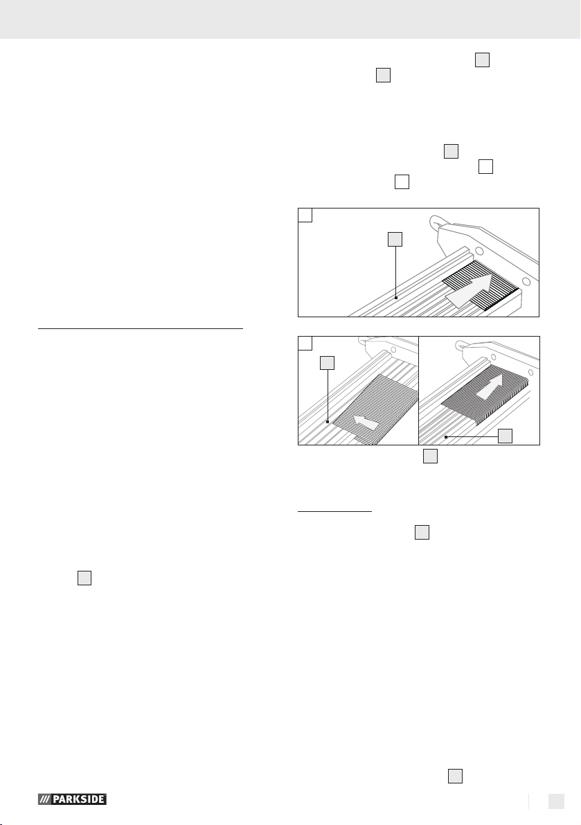
1. Presione la palanca del cargador 5 y retraiga
el cargador
6
.
NOTA: Tenga en cuenta que solamente las
grapas de 16 - 32 mm de longitud y los
clavos de 15 - 32 mm de longitud se pueden
colocar en el cargador.
2. Introduzca en el cargador
correspondientes (clavos, vea fig.
grapas, vea fig.
01
02
6
02
6
6
los remaches
01
o
).
6
3. Desplace el cargador 6 hasta que encaje.
j Conecte el aparato a una fuente de aire
comprimido adecuada.
1. A tal fin, presione el acoplamiento rápido del
tubo de aire comprimido (no suministrado)
contra el racor para la conexión de aire ¼“
4
AG
de la grapadora.
El cierre se realiza de forma automática.
2. Empalme el otro extremo del tubo de aire comprimido con el dispositivo reductor de presión
(filtro) situado en el compresor.
Q
Llenado del cargador
NOTA: Nunca coloque clavos en la abertura des-
tinada a las grapas. Esto provoca retención en el
mecanismo controlador e impide la correcta salida
de los remaches.
Q
Manejo
j Cargue el cargador 6 de la grapadora como
se describe en el capítulo „Llenado del cargador“.
j Ajuste la presión de trabajo correcta con un
dispositivo reductor de presión.
j Preste atención a que la presión máxima de
trabajo de 7 bar en el aparato no debe ser
superada. La sobrepresión de trabajo no aumenta la potencia, sino que solamente aumenta el consumo de presión neumática y acelera
el desgaste del aparato.
j Conecte el compresor.
j Deje el compresor funcionando una vez hasta
que se haya alcanzado la presión máxima en
la caldera y se desconecte el aparato.
j Ponga la taladradora sobre la pieza de traba-
jo y presione el disparador
2
.
9 ES
Page 10

Manejo / Limpieza y mantenimiento
NOTA: La taladradora está equi-
pada con un seguro de disparo
7
Gracias a él los remaches se
disparan cuando el orificio de la grapadora
neumática está presionado contra la pieza de
trabajo y el disparador ha sido presionado.
Gracias a este dispositivo de seguridad se asegura que los remaches, como grapas o clavos,
no se puedan disparar de forma incontrolada.
j Compruebe si el remache está clavado confor-
me a los requisitos.
- Si el remache sobresale, aumente la presión
neumática a pasos de 0,5 bar y vuelva a
comprobar el resultado.
- Si el remache está muy hundido, disminuya la
presión de aire a pasos de 0,5 bar hasta que
el resultado sea satisfactorio.
De todos modos, debería procurar trabajar con la
mínima presión de aire. Esto le proporcionar tres
importantes ventajas:
1) Ahorra energía,
2) Disminuye el nivel de ruido,
3) Reduce el desgaste de la remachadora.
j Evite activar la remachadora con el cargador
vacío.
INDICACIÓN: Es posible realizar un ajuste de
precisión con el tornillo moleteado
j Gire el tornillo moleteado
8
ferior
para hundir más el remache en la
9
.
9
hacia el tope in-
pieza de trabajo.
j Gire el tornillo moleteado
10
perior
para hundir menos el remache en la
9
hacia el tope su-
pieza de trabajo.
NOTA: la grapadora neumática se puede aplicar
contra una pieza de trabajo tanto horizontal como
vertical.
j Gire el embellecedor deflector de aire
1
para dirigir el aire despedido en la dirección
deseada.
j Tras finalizar el trabajo, separe el aparato del
compresor.
NOTA: Primero suelte el tubo del compresor
y justo después el tubo de alimentación del
aparato.
De este modo evitará que el tubo de suministre
se arremoline.
Q
Limpieza y mantenimiento
.
J ¡RIESGO DE QUEMADURAS! No
comience los trabajos de limpieza y mantenimiento hasta que la grapadora magnética se
haya enfriado por completo.
J ¡PELIGRO DE LESIONES! Antes de reali-
zar la limpieza y/o el mantenimiento del aparato, sepárelo necesariamente del suministro
de de aire comprimido.
Q
Mantenimiento
j Lubrique el aparato con regularidad. De este
modo mantendrá el buen funcionamiento y
alargará la vida útil del producto.
Lubricación con lubricador por neblina
NOTA: Como nivel de tratamiento después del
dispositivo reductor de presión, el lubricador por
neblina de aceite lubrica la grapadora neumática
de forma continuada y óptima. Un lubricador por
neblina reparte finas gotas de aceite por el aire
desprendido y garantiza así una lubricación
homogénea.
j Instale el lubricador por neblina después del
dispositivo reductor de presión (filtro). Para ello
introduzca la boquilla del lubricador en el
acoplamiento rápido del dispositivo reductor
de presión (filtro).
j Conecte luego el aparato neumático al
acoplamiento rápido previsto.
Lubricación manual
NOTA: Si no dispone de un lubricador por nebli-
na, proceda a lubricar el aparato antes de cada
puesta en funcionamiento
o bien tras un largo periodo de inactividad.
j Deje 3 - 5 gotas de aceite especial para
herramientas neumáticas en el racor para conexión de aire
j A continuación presione algunas veces el
disparador
j Añada 5 - 10 gotas tras un periodo de inactivi-
dad mayor de 5 días.
4
de la grapadora neumática
2
.
10 ES
Page 11

Limpieza y mantenimiento / Asistencia técnica / Garantía / Eliminación
Q
Limpieza
J Para la limpieza del aparato no utilice ningún
objeto afilado. No deben entrar líquidos en el
interior del dispositivo. Si lo hace, puede
dañar el aparato.
j Limpie regularmente el dispositivo, de preferen-
cia inmediatamente después de finalizar el
trabajo.
j Limpie la carcasa con un paño suave; no
utilice, en ningún caso, bencina, disolventes o
detergentes que puedan dañar el plástico.
j Guarde la grapadora neumática tras cada uso
en la maleta de transporte suministrada para
protegerla de la suciedad.
En caso de un tratamiento inadecuado e indebido,
uso de la fuerza bruta e intervenciones por asistencia técnica distinta a la nuestra autorizada, se extinguirá la garantía. Por está garantía no quedan
limitados sus derechos legales.
ES
Kompernass Service España
C/Invención 7
Polígono Industrial Los Olivos
28906 Getafe – Madrid
Tel.: 902 884663
Fax: 91/6652551
e-mail: support.es@kompernass.com
Q
Asistencia técnica
J
remachadora únicamente por perso-
Q
En este aparato dispone de 3 años de
garantía desde la fecha de compra. El
aparato ha sido producido con mucho
esmero y comprobado a conciencia antes
de la entrega. Guarde el ticket de caja
como justificante de compra. En caso de
garantía póngase en contacto con su
asistencia técnica telefónicamente. Sólo
así queda garantizado un envío gratuito
de su mercancía. Esta garantía es válida
para el primer adquirente y no es transferible.
Las prestaciones de garantía son únicamente aplicables a fallos de fabricación y de material, sin
embargo ello no engloba a las piezas de desgaste
o daños en partes frágiles tales como el interruptor
o acumuladores. El producto ha sido diseñado
únicamente para el uso privado y no para el uso
comercial.
¡ADVERTENCIA!
nal técnico cualificado y con repuestos
originales. De este modo se garantiza la
seguridad de la remachadora.
Garantía
Haga reparar la
Q
Eliminación
El embalaje se compone de materiales
reciclables que puede desechar en los
puntos locales de recogida selectiva.
¡No tire el producto en la
basura doméstica!
Para deshacerse de un aparato que ya no sirva
pregunte a las autoridades locales o municipales.
11 ES
Page 12

Declaración de conformidad / Fabricante
Q
Declaración de conformidad /
Fabricante
Nosotros, Kompernaß GmbH, Burgstr. 21,
D-44867 Bochum (Alemania), declaramos
por el presente documento que este producto
cumple las siguientes directivas europeas:
Normas armonizadas aplicadas:
EN 12100-1:2004
EN 12100-2:2004
EN 792-13:2000
Tipo / Denominación del aparato:
Grapadora neumática
Bochum, 31.07.2009
Hans Kompernaß
- Gerente -
Reservado el derecho a realizar modificaciones
para el perfeccionamiento del aparato.
12 ES
Page 13

Introduzione
Utilizzo secondo la destinazione d’uso .......................................................................Pagina 14
Dotazione ......................................................................................................................Pagina 14
Dotazione ......................................................................................................................Pagina 14
Dati tecnici .....................................................................................................................Pagina 14
Sicurezza della chiodatrice
Sicurezza sul lavoro ......................................................................................................Pagina 15
Indicazioni di sicurezza aggiuntive per chiodatrici ad aria compressa ....................Pagina 16
Accessori / componenti
aggiuntivi originali ........................................................................................................Pagina 17
Avvio
Collegamento alla fonti di alimentazione di aria compressa ....................................Pagina 17
Caricamento del magazzino ........................................................................................Pagina 17
Indice
Funzionamento ....................................................................................................Pagina 17
Manutenzione e pulizia
Manutenzione ...............................................................................................................Pagina 18
Pulizia.............................................................................................................................Pagina 19
Assistenza .................................................................................................................Pagina 19
Smaltimento ............................................................................................................Pagina 19
Garanzia ....................................................................................................................Pagina 19
Dichiarazione di conformità / Fabbricante....................................Pagina 20
13 IT/MT
Page 14

Introduzione
In queste istruzioni d'uso / sull'apparecchio sono riportati i seguenti pittogrammi:
Leggere il manuale di istruzioni
per l’uso!
Rispettare le avvertenze e le
indicazioni per la sicurezza!
Portare occhiali protettivi e cuffie
di protezione
Set pistola sparapunti
ad aria compressa
Q
Introduzione
Familiarizzarsi con le funzioni della chio-
datrice ed informarsi su come maneggiare
correttamente tali apparecchi prima di
avviare l‘apparecchio medesimo per la prima volta. A questo proposito leggere le istruzioni d’uso che
seguono. Conservare le presenti istruzioni d’uso in
buono stato. In caso di passaggio dell’apparecchio
a terzi della chiodatrice pneumatica consegnare
anche tutta la documentazione.
Q
Utilizzo secondo la
destinazione d’uso
Questo apparecchio è adatto per l‘esecuzione di
lavori di montaggio e di riparazione (vedi Fig. B,
C, D). Ogni utilizzo diverso del prodotto o una sua
modifica si considerano come non conformi alla
destinazione d’uso e determinano notevoli rischi di
incidenti. Il produttore declina ogni responsabilità
per eventuali danni derivanti da un utilizzo non
conforme alle modalità d’uso. Il prodotto è destinato solamente per l‘utilizzo in ambito privato.
Q
Dotazione
1
Diaframma di scarico (ruotabile)
2
Leva di comando
3
Manico
Tenere lontano i bambini
dalla chiodatrice!
Sicura di azionamento
Smaltire l’imballaggio dell’apparecchio in modo ecocompatibile
4
Nipplo di inserimento filettato ¼“ AG
5
Leva magazzino
6
Magazzino
7
Staffa di sicurezza
8
Battuta inferiore
9
Vite a testa zigrinata
10
Battuta superiore
Q
Dotazione
1 x set sparachiodi ad aria compressa
1 x valigetta
1 x olio speciale per aria compressa
1 x nipplo di inserimento filettato ¼‘‘ AG
(premontato)
1 x pacco di chiodi, 1000 pezzi
1 x pacco di graffe, 1000 pezzi
1 x paio di occhiali protettivi
1 x chiave a brugola, 3 mm
1 x chiave a brugola, 4 mm
1 x istruzioni d’uso
Q
Dati tecnici
Pressione di lavoro: max. 7 bar
Capacità di carico: 100 pezzi
Lunghezza dei chiodi: 15 - 32 mm
Lunghezza delle graffe: 16 - 32 mm
Larghezza delle graffe: 5,7 mm
Lunghezza consigliata
del tubo flessibile: Ø 9 mm
Qualità aria compressa: purificata, nebulizzata con
olio e priva di condensa
14 IT/MT
Page 15

Introduzione / Sicurezza della chiodatrice
Informazioni relative al rumore e
alle vibrazioni:
I valori di misurazione sono stati accertati in applicazione delle norme EN 12549:1999, EN ISO 4871.
Il livello di pressione acustica stimato A ammonta
tipicamente a 85,7 dB (A). Scostamento K = 3 dB.
Il livello di rumore durante il lavoro può superare
98,7 dB (A).
Questi valori rappresentano valori caratteristici e
non rispecchiano lo sviluppo del rumore presso il
luogo di utilizzo. Lo sviluppo del rumore presso il
luogo di utilizzo dipende ad esempio dall‘ambiente
di lavoro, dal pezzo lavorato, dal rivestimento del
pezzo, dal numero dei procedimenti di chiodatura.
A seconda delle condizioni presso la postazione di
lavoro e della struttura del pezzo vanno prese, se
necessario, misure individuali di riduzione del rumore, quale ad esempio la posa dei pezzi da lavorare
su basi fonoassorbenti, l‘impedimento di vibrazioni
del pezzo fissando o ricoprendo il pezzo medesimo,
oppure previa regolazione dell‘apparecchio alla
pressione minima necessaria per l‘esecuzione del
lavoro. In casi particolari è necessario indossare
cuffie a protezione dell‘udito.
Indossare cuffie protettive!
Valori complessivi di oscillazione ai sensi della
norma EN ISO 8662-11:
Valore di emissione dell’oscillazione a
Scostamento K = 1,5 m / s
2
= 2,0 m / s
h,D
Urti meccanici (vibrazioni)
Per la chiodatrice il valore caratteristico di vibrazione
è stato rilevato ai sensi della norma ISO 866211:1999: „Misurazione delle vibrazioni sull‘impugnatura di macchine utensili portatili: macchine
chiodatrici“ (vedere il paragrafo „Dati tecnici“).
Questo valore è un valore caratteristico riferito
all‘apparecchio, e non rappresenta l‘effetto sul sistema mano-braccio durante l‘uso dell‘apparecchio
stesso. L‘effetto sul sistema mano-braccio durante
l‘uso dell‘apparecchio dipende ad esempio dalla
forza della presa, dalla pressione esercitata, dalla
direzione di lavoro, dalla pressione dell‘aria predisposta, dal pezzo, dal supporto del pezzo.
Sicurezza della chiodatrice
ATTENZIONE!
zioni di sicurezze e le istruzioni riportate.
Eventuali inadempienze nell’osservanza della indicazioni di sicurezza e delle istruzioni può provocare
gravi lesioni e / o danni materiali.
CONSERVARE TUTTE LE INDICAZIONI DI SICUREZZA E LE ISTRUZIONI PER UN’EVENTUALA
FUTURA CONSULTAZIONE.
J Verificare prima di ogni utilizzo il
perfetto funzionamento dei dispositi-
vi di sicurezza e di scatto, nonché la
saldezza di tutte le viti e i dadi.
J Non effettuare alcuna manipolazione
della chiodatrice non conforme alle
norme.
J Non smontare o bloccare alcuna par-
te della chiodatrice, come ad esempio
la sicura di azionamento.
J Non effettuate alcuna „riparazione
d‘emergenza“ con mezzi inappro-
priati.
J La chiodatrice deve essere revisionata
regolarmente ed in modo adeguato.
J Evitare qualsiasi indebolimento o
danneggiamento dell‘apparecchio,
2
ad esempio con:
- colpi o incisioni;
- modifiche non autorizzate dalla
ditta costruttrice:
- utilizzo dell‘apparecchio su sagome
realizzate in materiali duri, quali ad
esempio l‘acciaio;
- c
adute o trascinamenti sul pavimento;
- utilizzo a guisa di martello;
- qualsiasi genere di intervento a forza.
Q
Sicurezza sul lavoro
J Non orientare mai un apparecchio
pronto per l‘uso verso se stessi o
un‘altra persona.
Leggere tutte le indica-
15 IT/MT
Page 16

Sicurezza della chiodatrice
J Tenere sempre l‘apparecchio in
modo tale che, in caso di un possibile
contraccolpo dovuto a guasti nell‘alimentazione elettrica o a punti più
duri del pezzo, la testa ed il corpo
non possano subire dei danni.
J Non fare mai scattare l‘apparecchio
a vuoto. In questo modo si eviterà il pericolo
di chiodi volanti o di un sovraccarico dell‘apparecchio stesso.
J Se lo si desidera trasportare, l‘appa-
recchio deve essere separato dalla
fonte di energia pneumatica, soprattutto se si utilizzano scale o si tiene
una postura non abituale.
J Sul posto di lavoro, portare l‘appa-
recchio solamente utilizzando l‘impugnatura e mai con il grilletto azionato.
J Fare attenzione alle condizioni della
postazione di lavoro. Le chiodatrici possono trapassare pezzi sottili oppure, lavorando
su angoli e spigoli, possono scivolare dal pezzo
e danneggiare altre persone.
J
esempio cuffie ed occhiali protettivi.
Utilizzare equipaggiamenti
protettivi adeguati, quali ad
L‘indossare dispositivi di protezione personale,
quali maschera antigas, scarpe di sicurezza
antiscivolo, elmetto di sicurezza o cuffie, a seconda della tipologia della chiodatrice e del
suo utilizzo, riduce il rischio di lesioni.
Indicazioni di sicurezza
aggiuntive per chiodatrici
ad aria compressa
ATTENZIONE!
Non superare mai la pressione di lavoro massi-
ma consentita di 7 bar. Per la regolazione della
pressione di lavoro utilizzare un riduttore di
pressione.
ATTENZIONE!
Non utilizzare mai ossigeno o altri gas infiam-
mabili quali fonti di energia.
J Mantenere la postazione di lavoro
sempre pulita e ben illuminata.
PERICOLO DI LESIONE!
PERICOLO DI LESIONE!
Disordine e postazioni di lavoro non illuminate
possono provocare incidenti.
J
essa. In caso di distrazione è possibile perdere
Durante l’utilizzo della chio-
datrice mantenere bambini
e altre persone lontani da
il controllo dell’apparecchio.
J Rimanere sempre attenti, fare atten-
zione a ciò che si fa e lavorare con la
chiodatrice in modo assennato. Non
utilizzare la chiodatrice quando si è
stanchi o si è sotto l‘influsso di droghe,
bevande alcoliche o medicinali. Un
solo attimo di disattenzione nell‘utilizzo
dell‘apparecchio può provocare serie lesioni.
J Evitare ogni postura innaturale del
corpo. Assicurarsi di essere in una
posizione eretta sicura e mantenere
in ogni istante l‘equilibrio. In questo
modo è possibile controllare la chiodatrice in
caso di eventuali situazioni improvvise.
J Staccare l‘apparecchio dalla fonte di alimenta-
zione di aria compressa prima di eseguire inter-
venti di riparazione e di manutenzione, nonché
prima di ogni trasporto dell‘apparecchio me-
desimo.
J PERICOLO DI LESIONE! Non avviare l‘ap-
parecchio quando la sicura di azionamento
è difettosa o è stata rimossa. In caso contrario
si potrebbero verificare situazioni che determi-
nano lesioni.
7
J Disinnestando il raccordo per tubo, tenere il
tubo flessibile ben fermo in mano, e ciò al fine
di evitare lesioni provocate da un tubo flessibile
che scatta all‘indietro.
J Per il collegamento all‘aria compressa utilizzare
esclusivamente un nipplo di inserimento filettato
da ¼“ ed un raccordo rapido.
J Non avvicinare mai le mani alla bocca dell‘ap-
parecchio quando questo è pronto al funziona-
mento. In caso contrario si potrebbero verificare
situazioni che determinano lesioni.
J Fare attenzione all‘eventuale presenza di danni.
Verificare l‘eventuale presenza di danni prima
di avviare l‘apparecchio. Non avviare in nessun
caso l‘apparecchio qualora esso presenti dei
difetti.
16 IT/MT
Page 17

Sicurezza della chiodatrice / Avvio / Funzionamento
J Non utilizzare oggetti acuminati. Non
introdurre mai oggetti acuminati e / o metallici
nell‘interno dell‘apparecchi.
Q
Accessori / componenti
aggiuntivi originali
J Utilizzare solamente accessori e com-
ponenti aggiuntivi indicati nelle istruzioni d‘uso. L‘utilizzo di componenti o di
accessori diversi da quelli indicati nelle istruzioni
d‘uso può rappresentare per l‘utilizzatore un
rischio di lesione.
Q
Avvio
Q
Collegamento alla fonti di alimentazione di aria compressa
NOTA: La chiodatrice ad aria compressa può es-
sere alimentata esclusivamente con aria compressa
filtrata e nebulizzata con olio, e non può superare
la pressione di lavoro massima di 7 bar misurata
all‘apparecchio. Per la regolazione della pressione
di lavoro il compressore deve essere fornito di un
riduttore di pressione.
1. Premere la leva del magazzino 5 ed tirare
indietro il magazzino
NOTA: Fare attenzione al fatto che nel ma-
gazzino possono essere inserite solamente
graffe aventi una lunghezza di 16 - 32 mm e
chiodi della lunghezza di 15 - 32 mm.
2. Inserire nel magazzino
chiodatura corrispondente (chiodi, vedi fig.
oppure graffe, vedi fig.
01
02
6
3. Fare avanzare il magazzino 6 fino a quando
non si incastra.
6
medesimo.
6
il materiale per
01
02
).
6
6
j Collegare l‘apparecchio ad una fonte adegua-
ta di alimentazione di aria compressa.
1. A questo scopo premere il raccordo rapido del
tubo flessibile dell‘aria compressa (non incluso
nella fornitura) sul nipplo di inserimento filettato
¼“ AG
Il serraggio avviene automaticamente.
2. Collegare l‘altra estremità del tubo flessibile
dell‘aria compressa con il riduttore di pressione
(con filtro) al compressore.
Q
Caricamento del magazzino
NOTA: Non porre mai chiodi nell‘apertura inter-
media destinata alle graffe. Ciò determinerebbe la
formazione di un ingorgo nel punzone ed impedirebbe un‘uscita corretta del materiale di chiodatura.
4
della chiodatrice.
Q
Funzionamento
j Caricare il magazzino
aria compressa come descritto nel capitolo
„Caricamento del magazzino“.
6
della chiodatrice ad
j Impostare la pressione di lavoro corretta agendo
sul riduttore di pressione.
j Fare attenzione a che la pressione massima di
lavoro di 7 bar all‘apparecchio non venga superata. Una pressione di lavoro eccessiva non
determina alcun aumento di potenza; al contrario, essa determina solamente un maggiore
consumo di aria compressa ed accelera l‘usura
dell‘apparecchio.
j Avviare il compressore.
j Fare funzionare il compressore fino a che la
pressione di caldaia é stata raggiunta e l‘apparecchio si spegne.
17 IT/MT
Page 18

j Porre la chiodatrice ad aria compressa sul
pezzo e premere la leva di comando
chiodatura lascia l‘apparecchio solamente
NOTA: La chiodatrice ad aria
compressa è fornita di una sicura
di azionamento
quando la bocca della chiodatrice ad aria
compressa è premuta contro il pezzo e la leva
di comando viene azionata. Questo dispositivo
di sicurezza assicura che nessun materiale di
chiodatura, quali graffe o chiodi, possa lasciare l‘apparecchio in modo incontrollato.
7
2
.
. Il materiale di
j Verificare se il materiale di chiodatura è stato
inserito in modo conforme ai requisiti.
- Qualora il materiale di chiodatura non fosse
entrato completamente nel pezzo, aumentare
la pressione dell‘aria in passi da 0,5 bar e di
volta in volta verificare nuovamente il risultato.
- Qualora il materiale di chiodatura fosse en-
trato troppo nel pezzo, ridurre la pressione
dell‘aria in passi da 0,5 bar fino a quando il
risultato non sia soddisfacente.
In ogni caso fare in modo che si lavori con la pressione dell‘aria minima possibile. Questo comporta
tre vantaggi determinanti:
1) Si risparmia energia,
2) Si riduce il livello di rumore,
3) Si riduce l‘usura della chiodatrice.
j Evitare di avviare la chiodatrice in presenza di
magazzino vuoto.
NOTA: Una regolazione fine è inoltre possibile
operando sulla vite a testa zigrinata
j Ruotare la vite a testa zigrinata
battuta inferiore
graffa più profondamente nel pezzo.
8
per inserire il chiodo o la
j Ruotare la vite a testa zigrinata
battuta superiore
graffa meno profondamente nel pezzo.
NOTA: La chiodatrice ad aria compressa può
essere posta su pezzi sia orizzontali che verticali.
10
per inserire il chiodo o la
j Ruotare il diaframma di scarico
zare l‘aria in uscita nella direzione desiderata.
9
.
9
contro la
9
contro la
1
per indiriz-
j Una volta conclusa la lavorazione staccare
l‘apparecchio dal compressore.
NOTA: Anzitutto staccare il tubo flessibile dal
compressore, e solamente in seguito rimuovere
il tubo flessibile di alimentazione dall‘apparecchio. In questo modo si evita il vorticare senza
controllo del tubo flessibile di alimentazione.
Q
Manutenzione e pulizia
J PERICOLO DI BRUCIATURE! Avviare i
lavori di pulizia e di manutenzione solamente
quando la chiodatrice ad aria compressa si è
completamente raffreddata.
J PERICOLO DI LESIONE! Staccare comple-
tamente l’apparecchio dal sistema di alimentazione dell‘aria compressa prima di eseguire
qualsiasi intervento di pulizia o di manutenzione.
Q
Manutenzione
j Lubrificare l‘apparecchio con regolarità. In
questo modo l‘apparecchio funzionerà perfettamente e verrà garantita una sua lunga vita
operativa.
Lubrificare con lubrificante nebulizzatore
NOTA: Quale livello di trattamento a valle del ri-
duttore di pressione, il lubrificante nebulizzatore
lubrifica la chiodatrice ad aria compressa in modo
continuo ed ottimale. Il lubrificante nebulizzatore
emette olio in gocce fini all‘aria che scorre ed in
questo modo assicura una lubrificazione regolare.
j Installare il lubrificatore nebulizzatore a valle
del riduttore di pressione con filtro. A questo
scopo inserire il nipplo di inserimento del nebulizzatore nell‘attacco rapido del riduttore di
pressione (con filtro).
j In seguito collegare l‘apparecchio ad aria com-
pressa all‘attacco rapido previsto allo scopo.
Lubrificazione manuale
NOTA: Qualora l‘utilizzatore non avesse a dispo-
sizione un nebulizzatore, lubrificare prima di ogni
avvio o dopo lunghe pause di esercizio.
j Applicare da 3 a 5 gocce di olio speciale per
apparecchi ad aria compressa nel nipplo di inserimento filettato
compressa.
4
della chiodatrice ad aria
18 IT/MT
Page 19

Manutenzione e pulizia / Assistenza / Smaltimento / Garanzia
j In seguito premere alcune volte la leva di
comando
2
.
j Applicare da 5 a 10 gocce d‘olio dopo una
pausa di esercizio superiore a cinque giorni.
Q
Pulizia
J Per la pulizia dell‘apparecchi non utilizzare
oggetti ruvidi. Nessun liquido deve penetrare
nell‘interno dell‘apparecchio. In caso contrario
l‘apparecchio potrebbe venirne danneggiato.
j Pulire l‘apparecchio con regolarità, possibil-
mente alla fine di ogni lavorazione.
j Pulire l‘alloggiamento con un panno asciutto -
non utilizzare in nessun caso benzina, solventi
o altre sostanze per la pulizia aggressive per
la plastica.
j Dopo ogni utilizzo riporre la chiodatrice ad
aria compressa nella valigetta in dotazione per
proteggerla dalle impurità.
Q
Assistenza
J
ATTENZIONE!
chiodatrice solamente da personale
tecnico qualificato e solamente con
pezzi di ricambio originali. In questo
modo si garantisce che la sicurezza della chiodatrice rimanga immutata.
Fare riparare la
Q
Garanzia
L‘apparecchio è garantito per 3 anni dalla
data di acquisto. L‘apparecchio è stato
prodotto con cura e collaudato a fondo
prima della consegna. Conservare lo
scontrino come prova d‘acquisto. In caso
di garanzia mettersi in contatto telefonico con il punto di assistenza competente.
Solo in questo modo possiamo garantire
la spedizione gratuita della merce. Questa
garanzia è valida solo nei confronti del
primo acquirente e non è trasferibile.
La garanzia è limitata a difetti di fabbricazione o
di materiali, non è estesa ai pezzi soggetti ad usura
o a danneggiamenti alle parti delicate, p. es.
l‘interruttore o batterie. Il prodotto è destinato
esclusivamente all‘uso domestico e non a quello
commerciale.
La garanzia decade in caso di impiego improprio
o manomissione,uso della forza e interventi non
eseguiti dalla nostra filiale di assistenza autorizzata.
Questa garanzia non limita i diritti legali del cliente.
IT
Kompernass Service Italia
Tel.: +39 199 400 441 (0,12 EUR/min.)
e-mail: support.it@kompernass.com
Q
Smaltimento
L’imballaggio è composto da materiali
ecologici, che possono essere smaltiti
presso i siti di riciclaggio locali.
Non gettare il prodotto nella
spazzatura domestica!
Informazioni sulle possibilità di smaltimento di apparecchi giunti al termine della loro vita utile sono
disponibili presso le amministrazioni comunali.
19 IT/MT
Page 20

Dichiarazione di conformità / Fabbricante
Q
Dichiarazione di conformità /
Fabbricante
L’azienda Kompernaß GmbH, Burgstr. 21,
D-44867 Bochum, Germania, dichiara la conformità del presente prodotto alle seguenti direttive UE:
Norme armonizzate applicate:
EN 12100-1:2004
EN 12100-2:2004
EN 792-13:2000
Tipo / Denominazione dell’apparecchio:
Set pistola sparapunti ad aria compressa
Bochum, 31.07.2009
Hans Kompernaß
- Amministratore -
Si riservano modifiche tecniche ai fini di
ulteriori sviluppi.
20 IT/MT
Page 21

Table of contents
Introduction
Proper use ......................................................................................................................Page 22
Features and equipment ...............................................................................................Page 22
Included items ...............................................................................................................Page 22
Technical data ...............................................................................................................Page 22
Fastener driving tool safety
Safety at work ...............................................................................................................Page 23
Additional safety advice for compressed air tackers ..................................................Page 24
Original accessories/attachments ...............................................................................Page 24
Bringing into use
Connecting the compressed air source .......................................................................Page 24
Loading the magazine ..................................................................................................Page 25
Operation .................................................................................................................Page 25
Maintenance and cleaning
Maintenance .................................................................................................................Page 26
Cleaning ........................................................................................................................Page 26
Service .........................................................................................................................Page 26
Warranty ...................................................................................................................Page 26
Disposal ......................................................................................................................Page 27
Declaration of Conformity / Manufacturer..................................Page 27
21 GB/MT
Page 22

Introduction
The following pictograms are used in these operating instructions / on the device:
Read the operating instructions!
Always heed warning labels and
safety instructions!
Wear hearing protection and
protective glasses
Air stapler set
Q
Introduction
Please make sure that you familiarise
yourself fully with the way the fastener
driving tool works before you use it for
the first time and that you understand how to handle
fastener driving tools correctly. To help you do this,
please read the accompanying operating instructions. Keep these instructions in a safe place. If
you pass the fastener driving tool on to anyone
else, please ensure that you also pass on all the
documentation.
Q
Proper use
Keep the tacker out of the
reach of children!
Trigger lock
Dispose packaging and appliance in
an environmentally-friendly way!
8
Lower stop
9
Knurled screw
10
Upper stop
Q
Included items
1 x Compressed air tacker
1 x Carrying case
1 x Compressed air special oil
1 x Threaded plug-in nipple, ¼‘‘ ext. dia.
(factory fitted)
1 x Pack of nails, 1000 No.
1 x Pack of staples, 1000 No.
1 x Safety glasses
1 x Allen key, 3 mm
1 x Allen key, 4 mm
1 x Operating instructions
This device is intended for assembly and repair work
(see Fig. B, C, D). Any other use or modification to
the device shall be considered as improper use
and could give rise to considerable risk of accident.
We will not accept liability for loss or damage arising
from improper use. The device is intended for private,
domestic use only.
Q
Features and equipment
1
Exhaust cover (rotatable)
2
Trigger
3
Handle
4
Threaded plug-in nipple ¼“ ext. dia.
5
Magazine lever
6
Magazine
7
Trigger lock
22 GB/MT
Q
Technical data
Working pressure: max. 7 bar
Magazine capacity: 100 No.
Nail length: 15 - 32 mm
Staple length: 16 - 32 mm
Staple width: 5.7 mm
Recommended
hose diameter: Ø 9 mm
Compressed air quality: cleaned, oiled and
condensate-free
Noise and vibration data:
The measured values are determined in accordance with EN 12549:1999, EN ISO 4871. The
A-weighted sound pressure level of the device is
typically 85.7 dB (A). Uncertainty K = 3 dB. The
Page 23

Introduction / Fastener driving tool safety
sound level while working may exceed 98.7 dB (A).
These values are device-related values and do not
represent the generation of noise at the place of use.
The noise generated at the place of use depends
e.g. on the working environment, workpiece, workpiece support, the number of tack driving cycles.
Depending on the workplace conditions and the
shape of the workpiece, it may be possible to take
job-specific noise reduction measures, such as placing the workpiece on a sound-damping substrate,
covering or clamping the workpiece to prevent vibration, setting the pressure to the lowest possible
value adequate for the job. In some cases, it may
be necessary to wear ear protection.
Wear ear protection!
Total vibration in accordance with EN ISO 8662-11:
Vibration emission value a
Uncertainty K = 1.5 m / s
Mechanical impact (vibration)
The vibration values for the fastener driving tool
were calculated in accordance with ISO 866211:1999 — Hand-held portable power tools —
Measurement of vibrations at the handle — Fastener driving tools (see Technical data). The value is a
device-related value and does not represent the
effect on the hand-arm system of using the device.
The effect on the hand-arm system of using the device depends e.g. on the tightness of your grip on
the handle, contact pressure, direction of working,
set working air pressure, workpiece, workpiece
support.
= 2.0 m / s
h,D
2
2
Fastener driving
tool safety
WARNING!
advice and instructions. Failure to observe
the safety advice and instructions could result in serious injury and/or damage to property.
KEEP ALL ThE SAFETY ADVICE AND INSTRUCTIONS IN A SAFE PLACE FOR FUTURE
REFERENCE.
Read all the safety
J Before you start work with the
device, check that its safety features
and trigger fittings are working
properly and that all screws, bolts
and nuts are fixed tightly in place.
J Do not carry out unauthorised ad-
justments or modifications to the
fastener driving tool.
J Never disassemble or block any part
of the fastener driving tool, such as
the trigger lock.
J Do not carry out any “emergency
repairs” using unsuitable means.
J The fastener driving tool must be
regularly and properly maintained
in accordance with the manufactur-
er’s instructions.
J Do not risk weakening or damaging
the device by e.g.:
- subjecting it to impact or engraving it,
- converting it in a manner not
approved by the manufacturer,
- using templates that are made from
a hard material, e.g. steel,
- allowing it to fall or pushing it over
the floor,
- using it like a hammer, or
- using it to apply any kind of force.
Q
Safety at work
J Never point a fastener driving tool
that is ready for use directly towards
yourself or another person.
J When working, hold the fastener
driving tool in such a way that your
head and body cannot be injured
should kickback occur as a result of
an interruption of the energy supply
or striking a hard spot in the work
piece.
J Never trigger the fastener driving
tool into open space. Otherwise you risk
injury from flying fasteners and/or overloading
the device.
J Disconnect the fastener driving tool
from the air pressure network before
carrying it to a different location, es-
23 GB/MT
Page 24

Fastener driving tool safety / Bringing into use
pecially if you are using a ladder or
moving your body in an unusual way.
J When at the workplace, always carry
the device by the handle and not
while the trigger is ready to operate.
J Pay attention to workplace conditions.
Tacks could be driven right through a thin
workpiece or shoot off and endanger people
when you are working on edges and corners.
J For your own safety, wear
suitable personal protective
equipment, such as ear and eye pro-
tection. The wearing of personal protective
equipment such as dust masks, non-slip safety
shoes, safety helmets or ear protectors, appropriate to the type of fastener driving tool used
and work undertaken, reduces the risk of injury.
Additional safety advice
for compressed air tackers
WARNING!
Never exceed the maximum allowable working
air pressure of 7 bar. Use a pressure reducer
to set the working air pressure.
WARNING!
Never use oxygen or other combustible gas as
the energy source.
J Keep your working area clean and
well lit. Untidy or poorly lit working areas
can lead to accidents.
J Keep children and other
ing tool. Distractions can cause you to lose
control of the device.
J Remain alert at all times, watch what
you are doing and always proceed
with caution when working with the
fastener driving tool. Do not use the
fastener driving tool if you are tired
or under the influence of drugs,
alcohol or medication. One moment of
carelessness when using the fastener driving
tool can lead to serious injury.
J Avoid placing your body in an unnat-
ural position. Keep proper footing
DANGER OF INJURY!
DANGER OF INJURY!
people away while you are
operating the fastener driv-
and balance at all times. By doing this,
you will be in a better position to control the
fastener driving tool, especially in unforeseen
circumstances.
J Disconnect the device from the compressed air
source before carrying out any repairs or main-
tenance of the device or moving it to another
location.
J DANGER OF INJURY! Never use the device
if the trigger lock
removed. Otherwise you could become injured.
7
is defective or has been
J When removing the hose coupling, hold the
hose tightly in your hand to avoid injury
caused by the hose shooting backwards.
J Always use a threaded plug-in nipple ¼‘‘ and
a quick release coupling for the compressed
air connection.
J Never place your hands near the opening
while the device is ready to operate. Other-
wise you could become injured.
J Look out for damage on the device.
Check the device for damage before bringing
it into use. Do not use the device if you discover
any defects.
J Do not use pointed implements. Never
poke pointed and/or metal objects into the
interior of the device.
Q
Original accessories/
attachments
J Use only the accessories and attach-
ments detailed in the operating
instructions. The use of driven fasteners or
accessories other than those recommended in
the operating instructions could lead to you
suffering an injury.
Q
Bringing into use
Q
Connecting the
compressed air source
NOTE: Operate the compressed air tacker only
with cleaned, oiled compressed air and never exceed
the maximum working air pressure at the device of
24 GB/MT
Page 25

Bringing into use / Operation
7 bar. A pressure reducer must be fitted to the compressor to regulate the working air pressure.
j Connect the device to a suitable source of
compressed air.
1. To do this press, the quick-release coupling of
the compressed air hose (not supplied) on to
the threaded plug-in nipple ¼“ ext. dia.
4
of
the compressed air tacker. It locks itself in
place automatically.
2. Connect the other end of the compressed air
hose to the (filter) / pressure reducer at the
compressor.
Q
Loading the magazine
NOTE: Never place nails into the intermediate
opening; this opening is intended for staples. Otherwise this could lead to a blockage in the driver
and prevent the proper exit of the driven fastener.
1. Press the magazine lever
magazine
6
.
5
and pull back the
NOTE: Note that only staples with a length
of 16 - 32 mm and nails with a length of
15 - 32 mm may be placed in the magazine.
2. Place some compliant driven fasteners (nails,
01
see Fig.
magazine
01
02
6
or staples, see Fig. 02) in the
6
.
6
6
3. Push the magazine 6 forward until it engages.
Q
Operation
6
j Load the magazine
of the compressed air
tacker, as described in the section about
“Loading the magazine”.
j Using the pressure reducer, set the correct
working air pressure.
j Ensure that the maximum working air pressure
at the device of 7 bar is not exceeded. An increased working air pressure does not improve
performance but only increases the consumption of compressed air and accelerates wear.
j Switch compressor on.
j Allow the compressor to run until the maximum
reservoir pressure has been reached and then
switch off the device.
j Place the compressed air tacker on to the
workpiece and press the trigger
NOTE: The compressed air tacker
is fitted with a trigger lock
2
.
7
. The
driven fastener only exits the device
if the opening of the compressed air tacker is
pressed against the workpiece and the trigger
is pressed. This safety feature ensures that
driven fasteners such as staples and nails cannot exit the device in an uncontrolled manner.
j Check whether the driven fastener is driven into
the workpiece in accordance with your requirements.
- If the driven fastener projects above the work-
piece surface, increase the compressed air
pressure in 0.5 bar steps until a satisfactory
result is achieved.
- If the driven fastener lies too far below the
workpiece surface, reduce the working
pressure in 0.5 bar steps until a satisfactory
result is achieved.
In any event, you should make every effort to work
using the lowest adequate compressed air pressure.
This brings you three important advantages:
1) You save energy,
2) You reduce the noise level,
3) You reduce the wear on the fastener driving tool.
j Avoid triggering the fastener driving tool if the
magazine is empty.
25 GB/MT
Page 26

Operation / Maintenance and cleaning / Service / Warranty
NOTE: Fine adjustment can also be done using
the knurled screw
j Turn the knurled screw
the lower stop
9
.
9
in the direction of
8
in order to sink the fastener
more deeply into the work piece.
j Turned the knurled screw
the upper stop
10
9
in the direction of
in order to sink the fastener
less deeply into the work piece.
NOTE: The compressed air tacker can be used on
a horizontal or on a vertical workpiece.
j Turn the exhaust cover
1 to direct the escap-
ing air in the desired direction.
j After you finish work, disconnect the device
from the compressor.
NOTE: First disconnect the hose from the
compressor and only then disconnect the
compressed air supply hose from the device.
This will ensure that the compressed air supply
hose does not wave around in an uncontrolled
manner.
Q
Maintenance and cleaning
J DANGER OF BURNS! Do not start any
cleaning or maintenance work on the compressed air tacker until it has completely
cooled down.
J DANGER OF INJURY! Always disconnect
the device from the compressed air source
before you clean or maintain it.
j Install the oil mist lubricator downstream of the
(filter)/pressure reducer. To do this, insert the
plug-in nipple of the oil mist lubricator into the
quick-release coupling of the (filter)/pressure
reducer.
j Then connect the compressed air device to the
quick-release coupling provided for it.
Manual lubrication
NOTE: If you do not have an oil mist lubricator,
you must lubricate the device before each period
of use and/or after long periods of disuse.
j Place 3 - 5 drops of compresses air special oil
into the threaded plug-in nipple
4
of the
compressed air tacker.
j Then press the trigger
2
a few times.
j Introduce 5 - 10 drops after a period of
disuse of more than 5 days.
Q
Cleaning
J Do not use sharp objects for cleaning the
device. Do not allow any liquids to enter the
device. Otherwise the device could be damaged.
j Clean the device frequently; for best results, do
this immediately after you have finished using it.
j Use a dry cloth to clean the housing – under
no circumstances use petrol, solvents or cleaning agents that attack plastic.
j Pack away the compressed air tacker in the
supplied carrying case after each use to
protect it from dirt.
Q
Maintenance
j Grease the device regularly. This will ensure
that it continues to work properly and has a
long service life.
Lubrication with the oil mist lubricator
NOTE: As an air preparation stage downstream
of the pressure reducer, an oil mist lubricator provides a continuous, optimum level of lubrication to
the compressed air tacker. An oil mist lubricator
gives off fine droplets of oil into the air and thus
ensures controlled lubrication.
26 GB/MT
Q
Service
J
WARNING!
Have your fastener
driving tool repaired only by qualified
specialist personnel using original
manufacturer parts only. This will ensure
that your fastener driving tool remains safe to use.
Q
Warranty
This appliance is guaranteed for 3 years
from the date of purchase. It has been care-
Page 27

Warranty / Disposal / Declaration of Conformity / Manufacturer
fully produced and meti-culously checked
before delivery. Please keep your receipt
as proof of purchase. Contact your service
centre by telephone in case of questions
pertaining to the warranty. Your goods
can
be transmitted free of cost only in this
manner. This warranty applies only to the
initial
purchaser and is non-transferable.
The warranty covers only material or manufacturing faults, not normal wear or damage to fragile
parts such as switches or rechargeable batteries.
The appliance is intended solely for private, not
commercial, use.
If this product has been subjected to improper or
inappropriate handling, abuse, or interventions not
carried out by one of our authorised sales and
service outlets, the warranty will be considered void.
This warranty does not affect your statutory rights.
GB
DES Ltd
Units 14-15
Bilston Industrial Estate
Oxford Street
Bilston (Great Britain)
WV14 7EG
Tel.: 0870 / 787-6177
Fax: 0870 / 787-6168
e-mail: support.uk@kompernass.com
Q
Declaration of Conformity /
Manufacturer
We, Kompernaß GmbH, Burgstr. 21,
D-44867 Bochum, Germany, declare that this
product complies with the following EU directives:
Applicable harmonised standards:
EN 12100-1:2004
EN 12100-2:2004
EN 792-13:2000
Type / Device description:
Air stapler set
Bochum, 31.07.2009
Hans Kompernaß
- Managing Director -
Q
Disposal
The packaging is wholly composed of
environmentally-friendly materials that can
be disposed of at a local recycling centre.
Do not dispose of the product with
household rubbish!
Contact your local refuse disposal authority for
more details of how to dispose of your worn out
electrical devices.
We reserve the right to make technical modifications
in the course of further development.
27 GB/MT
Page 28

28
Page 29

Inhaltsverzeichnis
Einleitung
Bestimmungsgemäßer Gebrauch .................................................................................Seite 30
Ausstattung ....................................................................................................................Seite 30
Lieferumfang ..................................................................................................................Seite 30
Technische Daten ..........................................................................................................Seite 30
Sicherheit des Eintreibgerätes
Arbeitssicherheit ............................................................................................................Seite 31
Ergänzende Sicherheitshinweise für Druckluft-Tacker .................................................Seite 32
Originalzubehör / -zusatzgeräte ..................................................................................Seite 32
Inbetriebnahme
Druckluftquelle anschließen .........................................................................................Seite 33
Magazin laden .............................................................................................................Seite 33
Bedienung ................................................................................................................Seite 33
Wartung und Reinigung
Wartung .........................................................................................................................Seite 34
Reinigung .......................................................................................................................Seite 34
Service .........................................................................................................................Seite 35
Garantie .....................................................................................................................Seite 35
Entsorgung ...............................................................................................................Seite 35
Konformitätserklärung / Hersteller ....................................................Seite 36
29 DE/AT/CH
Page 30

Einleitung
In dieser Bedienungsanleitung werden folgende Piktogramme / Symbole verwendet:
Bedienungsanleitung lesen! Kinder vom Eintreibgerät fernhalten!
Warn- und Sicherheitshinweise
beachten!
Tragen Sie einen Gehörschutz
und eine Schutzbrille
Druckluft-Tacker-Set
Q
Einleitung
Machen Sie sich vor der ersten Inbetrieb-
nahme mit den Funktionen des Eintreib-
gerätes vertraut und informieren Sie sich
über den richtigen Umgang mit Eintreibgeräten.
Lesen Sie hierzu die nachfolgende Bedienungsanleitung. Bewahren Sie diese Anleitung gut auf.
Händigen Sie alle Unterlagen bei Weitergabe des
Eintreibgerätes an Dritte ebenfalls aus.
Q
Bestimmungsgemäßer Gebrauch
Dieses Gerät ist für Montage- und Reparaturarbeiten geeignet (siehe Abb. B, C, D). Jede andere
Verwendung oder Veränderung des Gerätes gilt
als nicht bestimmungsgemäß und birgt erhebliche
Unfallgefahren. Für aus bestimmungswidriger Verwendung entstandene Schäden übernehmen wir
keine Haftung. Das Gerät ist nur für den privaten
Einsatz bestimmt.
Q
Ausstattung
1
Abluftblende (drehbar)
2
Auslöser
3
Handgriff
4
Gewindestecknippel ¼“ AG
5
Magazinhebel
6
Magazin
7
Auslösesicherung
8
unterer Anschlag
30 DE/AT/CH
Auslösesicherung
Entsorgen Sie Verpackung und Gerät
umweltgerecht!
9
Rändelschraube
10
oberer Anschlag
Q
Lieferumfang
1 x Druckluft-Tacker-Set
1 x Tragekoffer
1 x Druckluft-Spezialöl
1 x Gewindestecknippel, ¼‘‘ AG (vormontiert)
1 x Packung Nägel, 1000 Stk.
1 x Packung Klammern, 1000 Stk.
1 x Schutzbrille
1 x Inbusschlüssel, 3 mm
1 x Inbusschlüssel, 4 mm
1 x Bedienungsanleitung
Q
Technische Daten
Arbeitsdruck: max. 7 bar
Ladekapazität: 100 Stk.
Nagellänge: 15 - 32 mm
Klammerlänge: 16 - 32 mm
Klammerbreite: 5,7 mm
Empfohlener
Schlauchdurchmesser: Ø 9 mm
Druckluftqualität: gereinigt, Öl vernebelt
und kondensatfrei
Geräusch- und Vibrationsinformationen:
Messwerte ermittelt entsprechend EN 12549:1999,
EN ISO 4871. Der A-bewertete Schalldruckpegel
des Gerätes beträgt typischerweise 85,7 dB (A).
Unsicherheit K = 3 dB. Der Geräuschpegel beim
Arbeiten kann 98,7 dB (A) überschreiten.
Page 31

Einleitung / Sicherheit des Eintreibgerätes
Diese Werte sind gerätebezogene Kennwerte und
geben nicht die Geräuschentwicklung am Verwendungsort wieder. Die Geräuschentwicklung am Verwendungsort hängt z. B. ab von der Arbeitsumgebung, dem Werkstück, der Werkstückauflage, der
Zahl der Eintreibvorgänge.
Entsprechend den Arbeitsplatzverhältnissen und
der Werkstückgestaltung sind ggf. individuelle
Geräuschminderungsmaßnahmen durchzuführen,
wie z.B. Auflegen der Werkstücke auf schalldämpfende Unterlagen, Verhinderung von Vibration der
Werkstücke durch Einspannen oder Zudecken, Einstellen des für den Arbeitsvorgang erforderlichen
geringsten Druckes. In besonderen Fällen ist das
Tragen von persönlichem Gehörschutz erforderlich.
Gehörschutz tragen!
Schwingungsgesamtwerte nach EN ISO 8662-11:
Schwingungsemissionswert a
Unsicherheit K = 1,5 m / s
h,D
2
= 2,0 m / s
2
Mechanische Stöße (Vibration)
Für das Eintreibgerät wurde der Vibrationskennwert
ermittelt nach ISO 8662-11:1999 — Handgehaltene motorbetriebene Maschinen — Messung mechanischer Schwingungen am Handgriff — Eintreibgeräte (siehe Technische Daten). Der Wert ist ein
gerätebezogener Kennwert und stellt nicht die Einwirkung auf das Hand-Arm-System bei der Anwendung des Gerätes dar. Eine Einwirkung auf das
Hand-Arm-System bei der Anwendung des Gerätes
hängt z. B. ab von der Greifkraft, der Anpresskraft,
der Arbeitsrichtung, dem eingestellten Luftdruck,
dem Werkstück, der Werkstückauflage.
Sicherheit des
Eintreibgerätes
WARNUNG!
hinweise und Anweisungen.
Versäumnisse bei der Einhaltung der Sicherheitshinweise und Anweisungen können schwere Verletzungen
und / oder Sachschäden verursachen.
Lesen Sie alle Sicherheits-
BEwAhREN SIE ALLE SIChERhEITShINwEISE
UND ANwEISUNGEN FüR DIE ZUKUNFT AUF.
J Prüfen Sie vor jedem Arbeitsbeginn die
einwandfreie Funktion der Sicherheitsund Auslöseeinrichtungen sowie den
festen Sitz aller Schrauben und Muttern.
J Führen Sie keine unvorschriftsmäßigen
Manipulationen am Eintreibgerät durch.
J Demontieren oder blockieren Sie keine
Teile des Eintreibgerätes, wie z.B. eine
Auslösesicherung.
J Führen Sie keine „Notreparaturen“ mit
ungeeigneten Mitteln durch.
J Das Eintreibgerät ist regelmäßig und
sachgerecht nach Angaben des Herstellers zu warten.
J Vermeiden Sie jegliche Schwächung
und Beschädigung des Gerätes, z.B.
durch:
- Einschlagen oder Eingravieren,
- vom Hersteller nicht zugelassene
Umbaumaßnahmen
- Führen an Schablonen, die aus hartem
Material, z.B. Stahl, gefertigt sind,
- Fallenlassen auf oder Schieben über
den Fußboden,
- Handhabung als Hammer,
- jede Art von Gewalteinwirkung.
Q
Arbeitssicherheit
J Richten Sie ein betriebsbereites Ein-
treibgerät niemals direkt gegen sich
selbst oder auf andere Personen.
J Halten Sie das Eintreibgerät beim Ar-
beiten so, dass Kopf und Körper bei
einem möglichen Rückstoß infolge einer
Störung der Energieversorgung oder
von harten Stellen im Werkstück nicht
verletzt werden können.
J Lösen Sie das Eintreibgerät niemals in
den freien Raum aus. Sie vermeiden da-
durch Gefährdung durch frei fliegende Eintreibgegenstände und Überbeanspruchung des Gerätes.
J Zum Transportieren ist das Eintreibge-
rät vom Druckluftnetz zu trennen, ins-
31 DE/AT/CH
Page 32

Sicherheit des Eintreibgerätes
besondere wenn Sie Leitern benutzen
oder sich in ungewohnter Körperhaltung fortbewegen.
J Tragen Sie am Arbeitsplatz das Ein-
treibgerät nur am Griff und nicht mit
betätigtem Auslöser.
J Achten Sie auf die Arbeitsplatzver-
hältnisse. Eintreibgegenstände können even-
tuell dünne Werkstücke durchschlagen oder
beim Arbeiten an Ecken und Kanten von Werkstücken abgleiten und dabei Personen gefährden.
J
Körperschutzmittel, wie z.B. Gehör-
Verwenden Sie für Ihren per-
sönlichen Schutz geeignete
und Augenschutz. Das Tragen persönlicher
Schutzausrüstung wie Staubmaske, rutschfeste
Sicherheitsschuhe, Schutzhelm oder Gehörschutz, je nach Art und Einsatz des Eintreibgerätes, verringert das Risiko von Verletzungen.
Ergänzende
Sicherheitshinweise
für Druckluft-Tacker
WARNUNG!
Überschreiten Sie niemals den maximal zuläs-
sigen Arbeitsdruck von 7 bar. Verwenden Sie
zur Einstellung des Arbeitsdruckes einen Druckminderer.
WARNUNG!
Verwenden Sie niemals Sauerstoff oder andere
brennbare Gase als Energiequelle.
J Halten Sie Ihren Arbeitsbereich sauber
und gut beleuchtet. Unordnung und unbeleuch-
tete Arbeitsbereiche können zu Unfällen führen.
J
fern. Bei Ablenkung können Sie die Kontrolle
über das Gerät verlieren.
J Seien Sie stets aufmerksam, achten
Sie darauf, was Sie tun und gehen Sie
mit Vernunft an die Arbeit mit einem
Eintreibgerät. Benutzen Sie kein Eintreibgerät, wenn Sie müde sind oder
unter dem Einfluss von Drogen, Alkohol
VERLETZUNGSGEFAHR!
VERLETZUNGSGEFAHR!
Halten Sie Kinder und andere
Personen während der Benutzung des Eintreibgerätes
oder Medikamenten stehen. Ein Moment
der Unachtsamkeit beim Gebrauch des Eintreibgeräts kann zu ernsthaften Verletzungen führen.
J Vermeiden Sie eine abnormale Körper-
haltung. Sorgen Sie für einen sicheren
Stand und halten Sie jederzeit das
Gleichgewicht. Dadurch können Sie das
Eintreibgerät in unerwarteten Situationen besser
kontrollieren.
J Entfernen Sie vor Reparatur- und Instandhal-
tungsarbeiten sowie vor einem Transport das
Gerät von der Druckluftquelle.
J VERLETZUNGSGEFAHR! Nehmen Sie das
Gerät nicht in Betrieb wenn die Auslösesiche-
7
rung
defekt oder entfernt worden ist. An-
dernfalls können Verletzungen die Folge sein.
J Halten Sie beim Lösen der Schlauchkupplung
den Schlauch fest in der Hand, um Verletzungen,
hervorgerufen durch einen zurückschnellenden
Schlauch, zu vermeiden.
J Verwenden Sie für den Druckluftanschluss un-
bedingt einen Gewindestecknippel ¼‘‘ und
eine Schnellkupplung.
J Kommen Sie niemals mit Ihren Händen in die
Nähe der Mündung, während das Gerät betriebsbereit ist. Andernfalls können Verletzungen
die Folge sein.
J Achten Sie auf Beschädigung. Kontrol-
lieren Sie das Gerät vor Inbetriebnahme auf
etwaige Beschädigungen. Sollte das Gerät
Mängel aufweisen, darf es auf keinen Fall in
Betrieb genommen werden.
J Verwenden Sie keine spitzen Gegen-
stände. Führen Sie niemals spitze und / oder
metallische Gegenstände in das Innere des
Gerätes ein.
Q
Originalzubehör / -zusatzgeräte
J Benutzen Sie nur Zubehör und Zusatz-
geräte, die in der Bedienungsanleitung
angegeben sind. Der Gebrauch anderer als
in der Bedienungsanleitung empfohlener Eintreibgegenstände oder anderen Zubehörs kann
eine Verletzungsgefahr für Sie bedeuten.
32 DE/AT/CH
Page 33

Inbetriebnahme / Bedienung
Q
Inbetriebnahme
Q
Druckluftquelle anschließen
HINWEIS: Der Druckluft-Tacker darf ausschließ-
lich mit gereinigter, ölvernebelter Druckluft betrieben
werden und darf den maximalen Arbeitsdruck von
7 bar am Gerät nicht überschreiten. Zur Regulierung
des Arbeitsdruckes muss der Kompressor mit einem
Druckminderer ausgestattet sein.
j Schließen Sie das Gerät an eine geeignete
Druckluftquelle an.
1. Drücken Sie hierfür die Schnellkupplung des
Druckluft-Schlauches (nicht im Lieferumfang enthalten) auf den Gewindestecknippel ¼“ AG
4
des Druckluft-Tackers.
Die Verriegelung erfolgt automatisch.
2. Verbinden Sie das andere Ende des DruckluftSchlauches mit dem (Filter)-Druckminderer am
Kompressor.
Q
Magazin laden
HINWEIS: Legen Sie niemals Nägel in die Zwi-
schenöffnung welche für die Klammern bestimmt ist.
Dies führt zum Rückstau im Treiber und verhindert
den korrekten Austritt des Eintreibmaterials.
1. Drücken Sie den Magazinhebel
Sie das Magazin
6
zurück.
5
und ziehen
HINWEIS: Beachten Sie, dass Klammern nur
mit der Länge von 16 - 32 mm und Nägel mit
der Länge 15 - 32 mm in das Magazin eingelegt werden dürfen.
2. Legen Sie das entsprechende Eintreibmaterial
(Nägel, siehe Abb.
02
Abb.
) in das Magazin 6 ein.
01
01
oder Klammern, siehe
6
02
6
3. Schieben Sie das Magazin 6 vor, bis es einrastet.
Q
Bedienung
j Laden Sie das Magazin 6 des Druckluft-Tackers,
wie in Kapitel „Magazin laden“ beschrieben.
j Stellen Sie mit Hilfe des Druckminderers den
korrekten Arbeitsdruck ein.
j Achten Sie darauf, dass Sie den maximalen
Arbeitsdruck von 7 bar am Gerät nicht überschreiten. Ein überhöhter Arbeitsdruck bringt
keinen Leis tungsgewinn sondern erhöht lediglich den Druckluft-Verbrauch und beschleunigt
den Geräteverschleiß.
j Schalten Sie den Kompressor ein.
j Lassen Sie den Kompressor einmal so lange
laufen, bis der maximale Kesseldruck erreicht
wurde und das Gerät abschaltet.
j Setzen Sie den Druckluft-Tacker auf das Werk-
stück und drücken Sie den Auslöser
HINWEIS: Der Druckluft-Tacker ist
2
mit einer Auslösesicherung
gestattet. Das Eintreibmaterial verlässt
das Gerät erst, wenn die Mündung des Druck-
luft-Tackers gegen das Werkstück gedrückt und
der Auslöser betätigt wird. Durch diese Schutzvorrichtung wird sichergestellt, dass keine Eintreibgegenstände wie Klammern oder Nägel
das Gerät unkontrolliert verlassen können.
j Prüfen Sie, ob der Eintreibgegenstand den An-
forderungen entsprechend eingetrieben ist.
- Steht der Eintreibgegenstand vor, erhöhen Sie
den Luftdruck in Schritten von 0,5 bar und
prüfen jeweils erneut das Ergebnis.
- Ist der Eintreibgegenstand zu tief eingesenkt,
verringern Sie den Luftdruck in Schritten von
0,5 bar bis das Ergebnis befriedigt.
6
7
.
aus-
33 DE/AT/CH
Page 34

Bedienung / Wartung und Reinigung
Auf jeden Fall sollten Sie bemüht sein, mit dem jeweils geringsten Luftdruck zu arbeiten. Das bringt
für Sie drei wesentliche Vorteile:
1) Sie sparen Energie,
2) Sie verringern den Geräuschpegel,
3) Sie reduzieren den Verschleiß des Eintreibgerätes.
j Vermeiden Sie ein Auslösen des Eintreibgerätes
bei leerem Magazin.
HINWEIS: Eine Feineinstellung ist zudem mit der
Rändelschraube
j Drehen Sie die Rändelschraube
unteren Anschlag
9
möglich.
8
, um den Eintreibgegen-
9
gegen den
stand tiefer in das Werkstück einzusenken.
j Drehen Sie die Rändelschraube
oberen Anschlag
10
, um den Eintreibgegen-
9
gegen den
stand weniger tief in das Werkstück einzusenken.
HINWEIS: Der Druckluft-Tacker kann sowohl an
einem waagrechten als auch an einem senkrechten
Werkstück angesetzt werden.
j Drehen Sie die Abluftblende
1
, um die ausströmende Luft in die gewünschte Richtung zu
leiten.
j Trennen Sie das Gerät nach Abschluss der
Arbeit vom Kompressor.
HINWEIS: Lösen Sie zuerst den Schlauch
vom Kompressor und entfernen Sie erst danach
den Versorgungsschlauch von dem Gerät.
So vermeiden Sie ein unkontrolliertes Herumwirbeln des Versorgungsschlauches.
Q
Wartung
j Schmieren Sie das Gerät regelmäßig.
So erhalten Sie eine einwandfreie Funktion
und eine lange Produktlebensdauer.
Mit Nebelöler schmieren
HINWEIS: Als Aufbereitungsstufe nach dem
Druckminderer schmiert ein Nebelöler den DruckluftTacker kontinuierlich und optimal. Ein Nebelöler gibt
in feinen Tröpfchen Öl an die durchströmende Luft
ab und garantiert so eine regelmäßige Schmierung.
j Installieren Sie den Nebelöler nach dem
(Filter)-Druckminderer. Stecken Sie hierfür den
Stecknippel des Nebelölers in die Schnellkupplung des (Filter)-Druckminderers.
j Schließen Sie dann das Druckluft-Gerät an der
dafür vorgesehenen Schnellkupplung an.
Manuell schmieren
HINWEIS: Sollten Sie nicht über einen Nebelöler
verfügen, nehmen Sie vor jeder Inbetriebnahme
bzw. nach längeren Betriebspausen eine Schmierung vor.
j Lassen Sie 3 - 5 Tropfen Druckluft-Spezialöl in
den Gewindestecknippel
4
des Druckluft-Tacker
j Drücken Sie anschließend einige Male den
Auslöser
2
.
j Geben Sie 5 - 10 Tropfen nach einer Be-
triebspause von mehr als 5 Tagen hinein.
Q
Wartung und Reinigung
J VERBRENNUNGSGEFAHR! Beginnen Sie
mit den Reinigungs- und Instandhaltungsarbeiten
erst, wenn der Druckluft-Tacker vollständig abgekühlt ist.
J VERLETZUNGSGEFAHR! Trennen Sie das
Gerät unbedingt von der Druckluftversorgung,
bevor Sie es reinigen und / oder warten.
34 DE/AT/CH
Q
Reinigung
J Verwenden Sie keine scharfen Gegenstände
zur Reinigung des Gerätes. Es dürfen keine
Flüssigkeiten in das Innere des Gerätes gelangen.
Andernfalls könnte das Gerät beschädigt werden.
j Reinigen Sie das Gerät regelmäßig, am besten
immer direkt nach Abschluss der Arbeit.
j Reinigen Sie das Gehäuse mit einem trockenen
Tuch – verwenden Sie auf keinen Fall Benzin,
Lösungsmittel oder Reiniger, die Kunststoff
angreifen.
j Verpacken Sie den Druckluft-Tacker nach je-
dem Gebrauch im mitgelieferten Tragekoffer
um ihn vor Verunreinigungen zu schützen.
Page 35

Q
Service
Service / Garantie / Entsorgung
AT
J
Q
Sie erhalten auf dieses Gerät 3 Jahre Garantie ab Kaufdatum. Das Gerät wurde
sorgfältig produziert und vor Anlieferung
gewissenhaft geprüft. Bitte bewahren
Sie den Kassenbon als Nachweis für den
Kauf auf. Bitte setzen Sie sich im Garantiefall mit Ihrer Servicestelle telefonisch
in Verbindung. Nur so kann eine kostenlose Einsendung Ihrer Ware gewährleistet
werden. Diese Garantie gilt nur gegenüber
dem Erstkäufer und ist nicht übertragbar.
Die Garantieleistung gilt nur für Material- oder Fabrikationsfehler, nicht aber für Verschleißteile oder für
Beschädigungen an zerbrechlichen Teilen, z.B.
oder Akkus. Das Produkt ist lediglich für den privaten
und nicht für den gewerblichen Gebrauch bestimmt.
Bei missbräuchlicher und unsachgemäßer Behandlung, Gewaltanwendung und bei Eingriffen, die
nicht von unserer autorisierten Service-Niederlassung
vorgenommen wurden, erlischt die Garantie. Ihre
gesetzlichen Rechte werden durch diese Garantie
nicht eingeschränkt.
WARNUNG!
gerät nur von qualifiziertem Fachpersonal und nur mit Originalersatzteilen
reparieren. Damit wird sichergestellt, dass
die Sicherheit des Eintreibgeräts erhalten bleibt.
Garantie
Lassen Sie Ihr Eintreib-
Schalter
Kompernaß Service Österreich
Rittenschober KG
Gmundner Strasse 10
4816 Gschwandt (Austria)
Tel.: (+43) 0 76 12 / 6 26 05 16
Fax: (+43) 0 76 12 / 62 60 56
e-mail: support.at@kompernass.com
CH
Kompernass Service Switzerland
Tel.: +41 (0) 848 000 525
e-mail: support.ch@kompernass.com
Q
Entsorgung
Die Verpackung besteht aus umweltfreund-
lichen Materialien, die Sie über die örtlichen
Recyclingstellen entsorgen können.
Werfen Sie das Produkt nicht in den
Hausmüll!
Möglichkeiten zur Entsorgung des ausgedienten
Gerätes erfahren Sie bei Ihrer Gemeinde- oder
Stadtverwaltung
DE
Schraven
Service- und Dienstleistungs GmbH
Gewerbering 14
47623 Kevelaer, Germany
Tel.: +49 (0) 180 5 008107
(14 Ct/Min. aus dem dt. Festnetz
ggf. abweichende Preise aus den
Mobilfunknetzen)
Fax: +49 (0) 2832 3532
e-mail: support.de@kompernass.com
35 DE/AT/CH
Page 36

Konformitätserklärung / Hersteller
Q
Konformitätserklärung /
Hersteller
Wir, Kompernaß GmbH, Burgstr. 21,
D-44867 Bochum, Deutschland, erklären hiermit für
dieses Produkt die Übereinstimmung mit folgenden
EG-Richtlinien:
Angewandte harmonisierte Normen:
EN 12100-1:2004
EN 12100-2:2004
EN 792-13:2000
Typ / Gerätebezeichnung:
Parkside Druckluft-Tacker-Set
Bochum, 31.07.2009
Hans Kompernaß
- Geschäftsführer -
Technische Änderungen im Sinne der
Weiterentwicklung sind vorbehalten.
36 DE/AT/CH
Page 37

IAN 32999
KOMPERNASS GMBH
Burgstraße 21
D-44867 Bochum
© by ORFGEN Marketing
Estado de las informaciones · Versione delle informazioni · Last Information Update
Stand der Informationen: 07 / 2009 · Ident.-No.: 072009-ES / IT / MT / GB / DE / AT / CH
 Loading...