

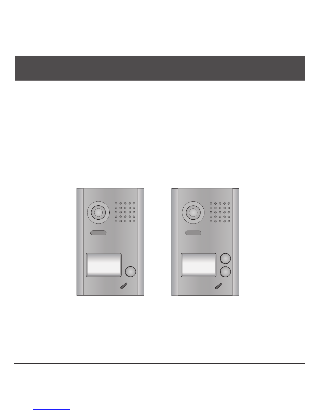
KomelCo DT602, DT602D User Manual
2 -Wire Intercom System
DT602 Series User Manual
DT-ENG-602/602D-V1 20140721
DT602 DT602D

CONTENTS
1.Parts and Functions............................................................................................. 1
2.Terminal Descriptions .......................................................................................... 1
3.Specications ...................................................................................................... 2
4.Mounting .............................................................................................................. 2
4.1 Mounting Without Rainy Cover ...................................................................... 2
4.2 Mounting With Rainy Cover ........................................................................... 3
4.3 Placing Name Label ...................................................................................... 3
5.System Wiring and Connections ......................................................................... 4
5.1 Basic Connection........................................................................................... 4
5.2 Electric Lock Connection ............................................................................... 4
5.2.1 Door Lock Controlled with Internal Power ............................................. 4
5.2.2 Door Lock Controlled with Dry Contact ................................................. 5
5.2.3 Unlock parameter setting(set on monitor) ............................................. 5
5.3 Multi Doorstations Connection....................................................................... 6
5.4 Multi Monitors Connection ............................................................................. 7
5.4.1 Basic IN-OUT Wiring Mode ................................................................. 7
5.4.2 With DBC4A Wiring Mode ................................................................... 8
6.Setup ................................................................................................................... 9
6.1
ID Settings of Doorstation
......................................................................... 9
6.2
Unlock Delay Time Setting
........................................................................ 10
6.3
Ringback Tone Setting
............................................................................... 11
7.Cables Requirements .......................................................................................... 12
-1-
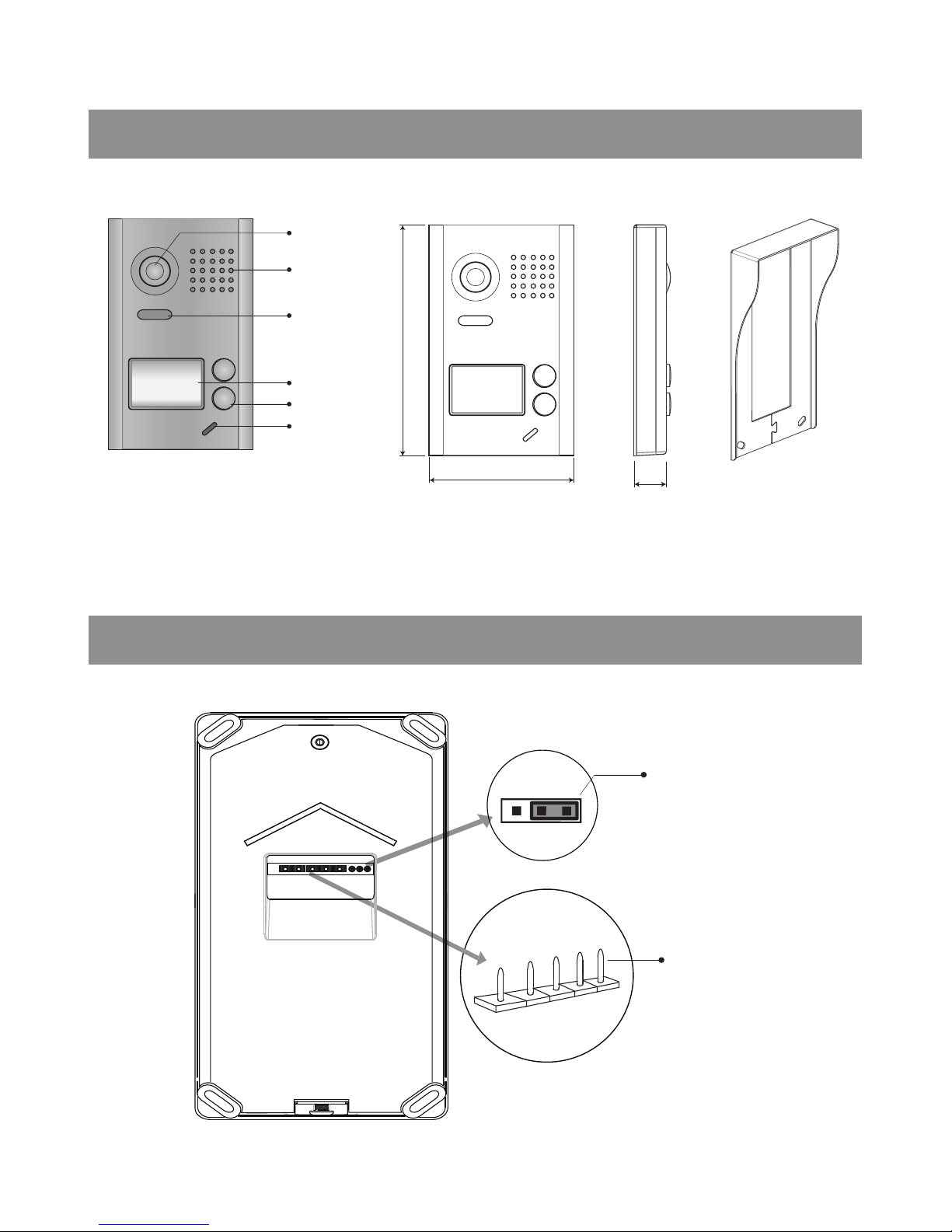
1.Parts and Functions
Camera Lens
Speaker
Nameplate
Call Button
Microphone
Night Light
Rainy Cover
23 mm
90 mm
145 mm
2.Terminal Descriptions
1 2 3
JP/LK
PL
S+
S-
Main Connect Port
BUS

-2-
•
JP/LK:
Lock control jumper, to select the lock type(see 5.2.1 , 5.2.2).
•
Main Connect Port:
To connect the bus line and the electronic locks.
• BUS: Connect to the bus line, no polarity.
• PL: External lock power input, connect to the power positive(power +).
• S+: Lock power(+) output.
• S-: Lock power(-) output, connect to the power(-) input of locks(only when using the camera to
power the locks, if using the external power supply for the locks, the S- will not be connected).
3.Specications
• Power Supply : DC 24V;
• Lock Power supply: 12Vdc, 300mA(Internal Power);
• Power Consumtion: Standby 33mA; Working status 110mA;
• Camera: Color ARS; 500 TV Lines;
• Unlocking time: 1~30s(Default 1s);
• Working temperature: -15ºC ~ 55ºC;
• Dimension: 145(H)×90(W)×23(D)mm(Without rainy cover).
4.Mounting
4.1 Mounting Without Rainy Cover
The host kit is
installed on the wall.
Connect the cable correctly.
1 2
54
3
6
Placing name label.
The surface shell kits are
installed on the host kit.
Use the screw to fix the host.
Installation is complete.

-3-
4.2 Mounting With Rainy Cover
The rainy cover and main
unit are installed on the wall.
Connect the cable correctly.
1 2
43
5
The surface shell kits are
installed on the host kit.
Use the screw to fix the host.
Installation is complete.
Rainy cover
The distance between the
top of main unit and rain
cover should be not less
than 3mm.
Main unit
Rainy cover
Main unit
≥3mm
4.3 Placing Name Label
Move the plastic cover away to open the transparent name label cover, insert a name paper, then put
the plastic cover back to the panel.
STEP 1
Unscrew the screws.
STEP 2
Replace name label.
 Loading...