

Page 1

Page 2

.
1 - 1
Page 3
.
BEFORE READING THIS MANUAL
FOREWORD
BEFORE READING THIS MANUAL
This manual gives details of the operation and methods of inspection and maintenance for this machine that must
be obeyed in order to use the machine safely. Most accidents are caused by the failure to follow fundamentalsafety
rules for the operation and maintenance of machines.
Read, understand and follow all precautions and warnings in this manual and on the machine before performing
operation and maintenance. Failure to do so may result in serious injury or death.
Komatsu cannot predict every circumstance that might involve a potential hazard when the machine is used.
Therefore, the safety messages in this manual and on the machine may not include all possible safety precautions.
If you carry out any operation, inspection, or maintenance under conditions that are not described in this manual,
understand that it is your responsibility to take the necessary precautions to ensure safety. In no event should you
or others engage in the prohibited uses or actions described in this manual. Improper operation and maintenance
of the machine can be hazardous and could result in serious injury or death.
If you sell the machine, be sure to give this manual to the new owner together with the machine.
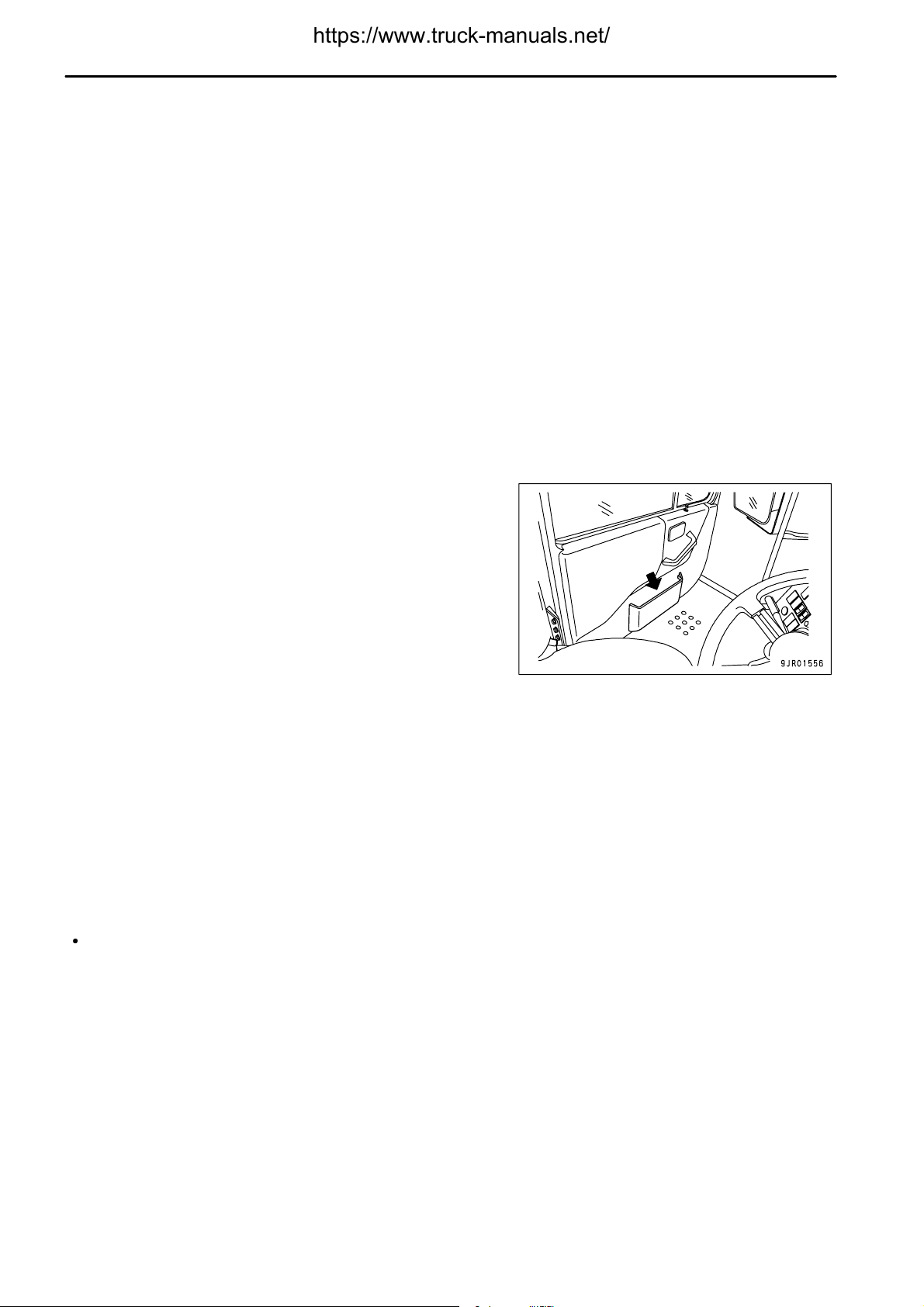
Always keep this Operation and Maintenance Manual in the
location shown on the right so that all relevant personnel can read
it at any time.
Storage location for the Operation and Maintenance Manual:
On inside of left door
If this manual is lost or damaged, contact your distributor immediately to arrange for its replacement. For details
regarding the machine serial No. you will need to provide your Komatsu distributor,see "TABLE TO ENTER SERIAL
NO. AND DISTRIBUTOR (PAGE 1-6)".
This manual uses the international units (SI) for units of measurement. For reference, units that have been used in
the past are given in ( ).
The explanations, values, and illustrations in this manual have been prepared based on the latest information
available as of the date of its publication. Continuing improvements in the design of this machine may lead to
additional changes that are not reflected in this manual. Consult Komatsu or your Komatsu distributor for the latest
available information concerning your machine or with questions regarding information contained in this manual.
The numbers in circles in the illustrations correspond to the numbers in ( ) in the text.
(For example:1 → (1))
Komatsu delivers machines that comply with all applicable regulations and standards of the country to which it has
been shipped. If this machine has been purchased in another country, it may lack certain safety devices and
specifications that are necessary for use in your country. If there is any question about whether your product
complies with the applicable standards and regulations of your country, consult Komatsu or your Komatsu
distributor before operating the machine.
1 - 2
Page 4

.
FOREWORD
SAFETY INFORMATION
SAFETY INFORMATION
To enable you to use the machine safely, and to prevent injury to operators, service personnel or bystanders, the
precautions and warnings included in this manual and the safety signs attached to the machine must always be
followed.
To identify important safety messages in the manual and on the machine labels, the following signal words are used.
The "Safety Alert Symbol" identifies important safety messages on machines, in manuals, and elsewhere. When
you see this symbol, be alert to the risk of personal injury or death. Follow the instructions in the safety message.
This signal word indicates an imminently hazardous situation which, if not avoided, will
result in death or serious injury.
This signal word indicates a potentially hazardous situation which, if not avoided, could
result in death or serious injury.
This signal word indicates a potentially hazardous situation exists which, if not avoided,
may result in minor or moderate injury.
The following signal words are used to alert you to information that must be followed to avoid damage to the
machine.
This precaution is given where the machine may be damaged or the service life reduced if
the precaution is not followed.
This word is used for information that is useful to know.
1 - 3
Page 5
.
INTENDED USE
FOREWORD
INTENDED USE
USE OF MACHINE
This Komatsu machine is designed to be used mainly for the following work:
Traveling with a load
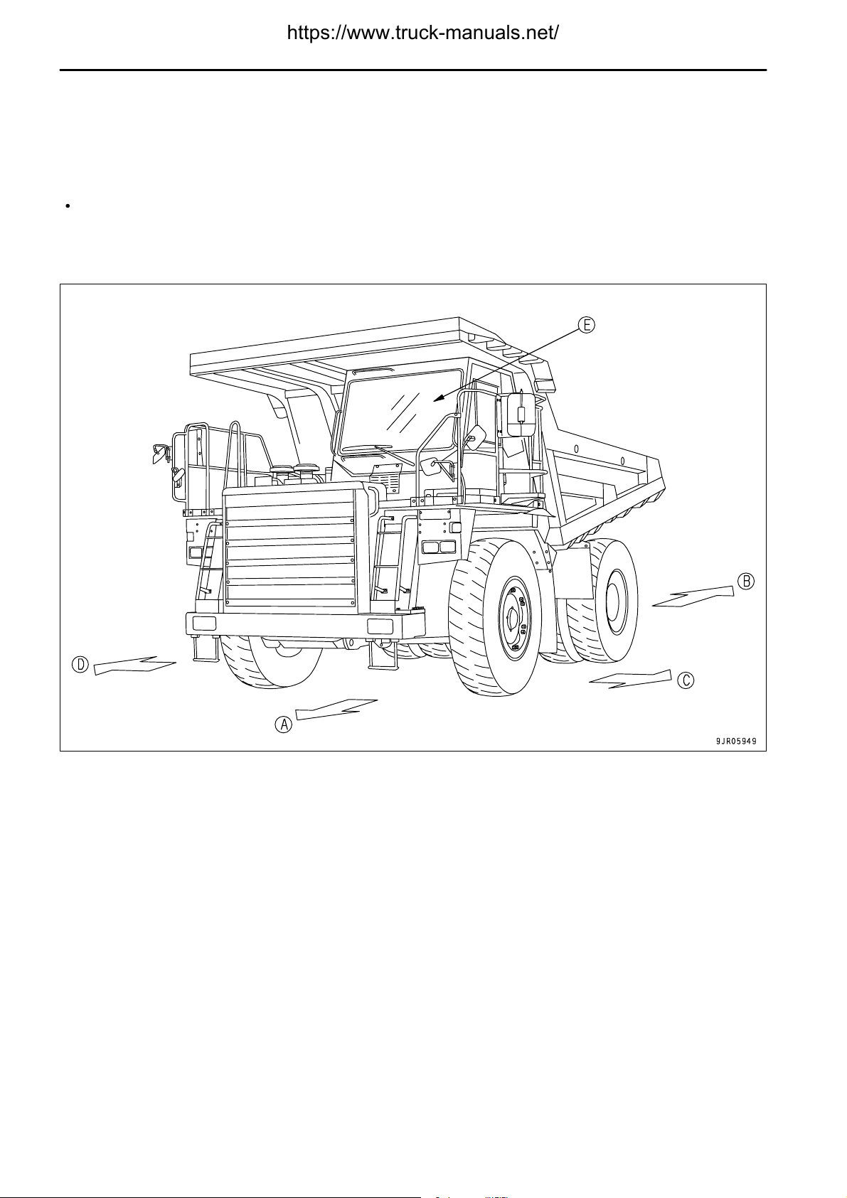
DIRECTIONS OF MACHINE
In this manual, the directions of the machine (front, rear, left, right) are determined according to the view from the
operator's seat in the direction of travel (front) of the machine.
(D)
(A)
(B)
(C)
FRONT
REAR
LEFT
RIGHT
(E)
OPERATOR'S SEAT
VISIBILITY FROM OPERATOR'S SEAT
This machine complies with the visibility standard (ISO 5006).
This machine maintains a close visibility of a height of 1.5 m at a point 1 m away from the outside surface of the
machine, and a visibility for a circumference of 12 m.
1 - 4
Page 6
.
FOREWORD
LOCATION OF PLATES, TABLE TO ENTER SERIAL NO. AND DISTRIBUTOR
LOCATION OF PLATES, TABLE TO ENTER SERIAL NO. AND
DISTRIBUTOR
When requesting service or ordering replacement parts, please inform your Komatsu distributor of the following
items.
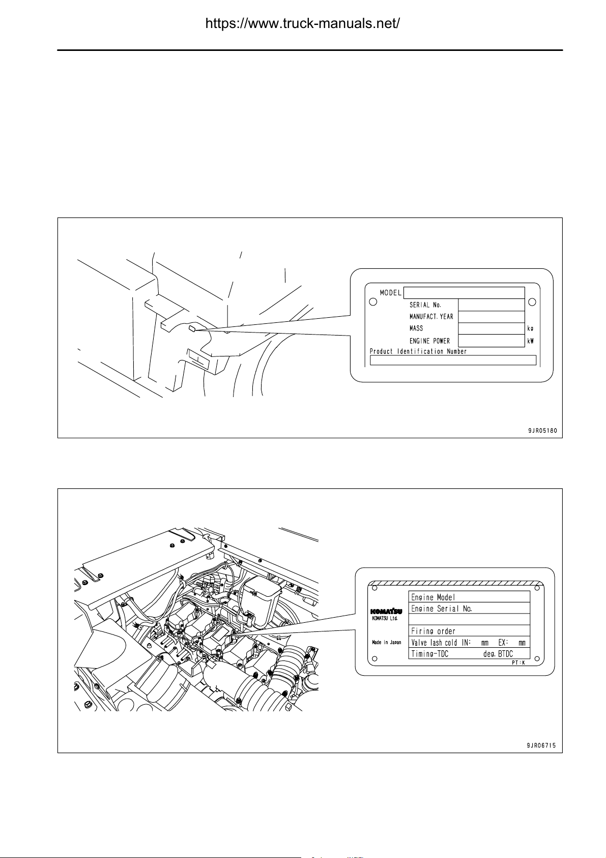
PRODUCT IDENTIFICATION NUMBER (PIN)/MACHINE SERIAL NO. PLATE
It is located on the left front end of the frame.
The design of the nameplate differs according to the territory.
ENGINE SERIAL NO. PLATE
On the top of the engine cylinder head cover.
1 - 5
Page 7

.
LOCATION OF PLATES, TABLE TO ENTER SERIAL NO. AND DISTRIBUTOR
FOREWORD
SERVICE METER POSITION
It is at the center bottom of the machine monitor.
TABLE TO ENTER SERIAL NO. AND DISTRIBUTOR
Machine serial No.
Engine serial No.
Product identification number (PIN)
Distributor name
Address
Service Personnel
Phone/Fax
1 - 6
Page 8

.
FOREWORD
CONTENTS
CONTENTS
FOREWORD 1- 1
BEFORE READING THIS MANUAL 1- 2
SAFETY INFORMATION 1- 3
INTENDED USE 1- 4
USE OF MACHINE 1- 4
DIRECTIONS OF MACHINE 1- 4
VISIBILITY FROM OPERATOR'S SEAT 1- 4
LOCATION OF PLATES, TABLE TO ENTER SERIAL NO. AND DISTRIBUTOR 1- 5
PRODUCT IDENTIFICATION NUMBER (PIN)/MACHINE SERIAL NO. PLATE 1- 5
ENGINE SERIAL NO. PLATE 1- 5
SERVICE METER POSITION 1- 6
TABLE TO ENTER SERIAL NO. AND DISTRIBUTOR 1- 6
SAFETY 2- 1
SAFETY 2- 2
SAFETY LABELS 2- 5
POSITION FOR ATTACHING SAFETY LABELS 2- 6
SAFETY LABELS 2- 7
GENERAL PRECAUTIONS COMMON TO OPERATION AND MAINTENANCE 2- 11
PRECAUTIONS BEFORE STARTING OPERATION 2- 11
PREPARATIONS FOR SAFE OPERATION 2- 11
FIRE PREVENTION 2- 13
PRECAUTIONS WHEN GETTING ON OR OFF MACHINE 2- 14
DO NOT GET CAUGHT IN DUMP BODY 2- 16
PRECAUTIONS RELATED TO PROTECTIVE STRUCTURES 2- 16
UNAUTHORIZED MODIFICATION 2- 16
PRECAUTIONS RELATED TO ATTACHMENTS AND OPTIONS 2- 17
PRECAUTIONS WHEN RUNNING ENGINE INSIDE BUILDING 2- 17
PRECAUTIONS FOR OPERATION 2- 18
PRECAUTIONS FOR JOBSITE 2- 18
STARTING ENGINE 2- 20
OPERATION 2- 22
TRANSPORTATION 2- 26
TOWING 2- 27
PRECAUTIONS FOR MAINTENANCE 2- 28
PRECAUTIONS BEFORE STARTING INSPECTION AND MAINTENANCE 2- 28
PRECAUTIONS FOR INSPECTION AND MAINTENANCE 2- 32
TIRES 2- 37
OPERATION 3- 1
GENERAL VIEW 3- 2
GENERAL VIEW OF MACHINE 3- 2
GENERAL VIEW OF CONTROLS AND GAUGES 3- 3
EXPLANATION OF COMPONENTS 3- 5
MACHINE MONITOR 3- 5
OTHER FUNCTIONS OF MACHINE MONITOR 3- 26
SWITCHES 3- 30
CONTROL LEVERS AND PEDALS 3- 39
BODY PIVOT PIN 3- 44
LOCATION OF FIRE EXTINGUISHER 3- 44
DUST INDICATOR 3- 45
1 - 7
Page 9

.
CONTENTS
FUSES 3- 46
CAR RADIO 3- 49
CAR STEREO 3- 55
AIR CONDITIONER 3- 64
OPERATION 3- 70
CHECK BEFORE STARTING ENGINE 3- 70
STARTING ENGINE 3- 89
OPERATIONS, CHECKS AFTER STARTING ENGINE 3- 91
STOPPING ENGINE 3- 92
CHECKS AFTER STOPPING ENGINE 3- 92
MOVING MACHINE OFF (FORWARD, REVERSE), STOPPING 3- 93
SHIFTING GEAR 3- 98
TRAVELING DOWNHILL 3-100
STEERING THE MACHINE 3-109
LOADING OPERATIONS 3-109
DUMP OPERATIONS 3-110
PRECAUTIONS FOR OPERATION 3-111
PARKING MACHINE 3-112
CHECKS AFTER COMPLETION OF WORK 3-113
LOCKING 3-113
HANDLING TIRES 3-114
DETERMINING AND MAINTAINING TRAVEL ROAD 3-117
DETERMINING TRAVEL ROAD 3-117
MAINTAINING TRAVEL ROAD 3-117
TRANSPORTATION 3-118
PRECAUTIONS WHEN TRANSPORTING 3-118
STEPS FOR TRANSPORTATION 3-118
METHOD OF SECURING MACHINE 3-118
METHOD OF LIFTING MACHINE 3-119
COLD WEATHER OPERATION 3-122
PRECAUTIONS FOR LOW TEMPERATURE 3-122
PRECAUTIONS AFTER COMPLETION OF WORK 3-123
AFTER COLD WEATHER 3-124
LONG-TERM STORAGE 3-125
BEFORE STORAGE 3-125
DURING STORAGE 3-125
AFTER STORAGE 3-125
PRECAUTIONS BEFORE TRAVELING AFTER LONG-TERM STORAGE 3-125
TROUBLESHOOTING 3-126
AFTER RUNNING OUT OF FUEL 3-126
IF TRANSMISSION HAS TROUBLE 3-126
METHOD OF LOWERING DUMP BODY IN EMERGENCY 3-127
METHOD OF TOWING MACHINE 3-129
IF BATTERY IS DISCHARGED 3-133
OTHER TROUBLE 3-137
MAINTENANCE 4- 1
GUIDES TO MAINTENANCE 4- 2
OUTLINE OF SERVICE 4- 5
HANDLING OIL, FUEL, COOLANT, AND PERFORMING OIL CLINIC 4- 5
OUTLINE OF ELECTRIC SYSTEM 4- 9
FOREWORD
1 - 8
Page 10

.
FOREWORD
WEAR PARTS 4- 10
WEAR PARTS LIST 4- 10
RECOMMENDED FUEL, COOLANT, AND LUBRICANT 4- 11
USE OF FUEL, COOLANT AND LUBRICANTS ACCORDING TO AMBIENT TEMPERATURE 4- 12
RECOMMENDED BRANDS, RECOMMENDED QUALITY FOR PRODUCTS OTHER THAN
KOMATSU GENUINE OIL 4- 14
STANDARD TIGHTENING TORQUES FOR BOLTS AND NUTS 4- 15
TORQUE LIST 4- 15
PERIODIC REPLACEMENT OF SAFETY CRITICAL PARTS 4- 16
SAFETY CRITICAL PARTS 4- 17
MAINTENANCE SCHEDULE CHART 4- 18
MAINTENANCE SCHEDULE CHART 4- 18
SERVICE PROCEDURE 4- 21
INITIAL 250 HOURS SERVICE (ONLY AFTER THE FIRST 250 HOURS) 4- 21
WHEN REQUIRED 4- 22
CHECK BEFORE STARTING 4- 48
EVERY 250 HOURS SERVICE 4- 49
EVERY 500 HOURS SERVICE 4- 61
EVERY 1000 HOURS SERVICE 4- 67
EVERY 2000 HOURS SERVICE 4- 79
EVERY 4000 HOURS SERVICE 4- 82
EVERY 8000 HOURS SERVICE 4- 84
EVERY 15000 HOURS SERVICE 4- 85
SPECIFICATIONS 5- 1
SPECIFICATIONS 5- 2
ATTACHMENTS, OPTIONS 6- 1
SELECTING DUMP BODY 6- 2
HANDLING AIR SUSPENSION SEAT 6- 3
SEAT ADJUSTMENT 6- 3
REMOVAL AND INSTALLATION OF HEADREST 6- 5
HANDLING AUTOMATIC SPIN REGULATOR (ASR) 6- 6
EXPLANATION OF COMPONENTS 6- 6
ACTUATION OF ASR SYSTEM 6- 7
PRECAUTIONS WHEN USING 6- 7
BLEEDING AIR FROM ASR CIRCUIT 6- 8
HANDLING ABS 6- 9
EXPLANATION OF COMPONENTS 6- 9
ABS SYSTEM CHECK AFTER STARTING ENGINE 6- 11
OPERATION OF ABS 6- 11
PRECAUTIONS WHEN USING 6- 12
HANDLING PAYLOAD METER II (CARD TYPE) 6- 13
METHOD OF USING ACCURATELY 6- 14
GENERAL LOCATIONS 6- 15
CONTENT OF DISPLAY (CONTROLLER, EXTERNAL DISPLAY LAMPS) 6- 20
EXTERNAL DISPLAY LAMPS 6- 24
DETAILS OF DATA STORED IN MEMORY OF PAYLOAD METER 6- 26
OPERATION OF SWITCHES 6- 31
PROBLEM AND WARNING DISPLAY (ERROR CODE) 6- 53
WHEN ERROR CODE F-09 IS DISPLAYED (PROCEDURE FOR REPLACING BATTERY) 6- 60
CONTENTS
1 - 9
Page 11

.
CONTENTS
OPERATION WHEN ERROR CODE F.CAL IS DISPLAYED OR CONTROLLER HAS BEEN
REPLACED 6- 63
ARSC (AUTOMATIC RETARDER SPEED CONTROL) 6- 66
EXPLANATION OF COMPONENTS 6- 67
METHOD OF OPERATION 6- 70
USE OF REAR VIEW MONITOR 6- 73
NAME AND FUNCTON OF EACH PART OF REAR VIEW MONITOR 6- 73
SETTING OF REAR VIEW MONITOR 6- 76
CAUTIONS WHEN USING REAR VIEW MONITOR 6- 76
HANDLING DUMPING COUNTER 6- 77
HANDLING MACHINES EQUIPPED WITH KOMTRAX 6- 78
BASIC PRECAUTIONS 6- 78
INDEX 7- 1
FOREWORD
1 - 10
Page 12

.
2 - 1
Page 13

.
SAFETY
SAFETY
SAFETY
SAFETY LABELS 2- 5
POSITION FOR ATTACHING SAFETY LABELS 2- 6
SAFETY LABELS 2- 7
GENERAL PRECAUTIONS COMMON TO OPERATION AND MAINTENANCE 2- 11
PRECAUTIONS BEFORE STARTING OPERATION 2- 11
ENSURING SAFE OPERATION 2- 11
UNDERSTANDING THE MACHINE 2- 11
PREPARATIONS FOR SAFE OPERATION 2- 11
PRECAUTIONS REGARDING SAFETY-RELATED EQUIPMENT 2- 11
INSPECTING MACHINE 2- 11
WEAR WELL-FITTING CLOTHES AND PROTECTIVE EQUIPMENT 2- 11
KEEP MACHINE CLEAN 2- 12
PRECAUTIONS INSIDE OPERATOR'S COMPARTMENT 2- 12
PROVIDE FIRE EXTINGUISHER AND FIRST AID KIT 2- 12
IF ANY PROBLEM IS FOUND 2- 12
FIRE PREVENTION 2- 13
ACTION IF FIRE OCCURS 2- 13
PRECAUTIONS TO PREVENT FIRE 2- 13
PRECAUTIONS WHEN GETTING ON OR OFF MACHINE 2- 14
USE HANDRAILS AND STEPS WHEN GETTING ON OR OFF MACHINE 2- 14
NO JUMPING ON OR OFF MACHINE 2- 14
NO PEOPLE ON DUMP BODY 2- 14
PRECAUTIONS WHEN STANDING UP FROM OPERATOR'S SEAT 2- 15
PRECAUTIONS WHEN LEAVING MACHINE 2- 15
EMERGENCY EXIT FROM OPERATOR'S CAB 2- 15
DO NOT GET CAUGHT IN DUMP BODY 2- 16
PRECAUTIONS RELATED TO PROTECTIVE STRUCTURES 2- 16
UNAUTHORIZED MODIFICATION 2- 16
PRECAUTIONS RELATED TO ATTACHMENTS AND OPTIONS 2- 17
PRECAUTIONS WHEN RUNNING ENGINE INSIDE BUILDING 2- 17
2 - 2
Page 14

.
SAFETY
PRECAUTIONS FOR OPERATION 2- 18
PRECAUTIONS FOR JOBSITE 2- 18
INVESTIGATE AND CONFIRM JOBSITE CONDITIONS 2- 18
WORKING ON LOOSE GROUND 2- 18
DO NOT GO CLOSE TO HIGH-VOLTAGE CABLES 2- 18
ENSURE GOOD VISIBILITY 2- 19
CHECKING SIGNS AND SIGNALMAN'S SIGNALS 2- 19
BEWARE OF ASBESTOS DUST 2- 19
STARTING ENGINE 2- 20
USE WARNING TAGS 2- 20
CHECKS BEFORE STARTING ENGINE 2- 20
PRECAUTIONS WHEN STARTING ENGINE 2- 21
PRECAUTIONS IN COLD AREAS 2- 21
STARTING WITH BOOSTER CABLES 2- 21
OPERATION 2- 22
CHECKS BEFORE OPERATION 2- 22
PRECAUTIONS WHEN TRAVELING IN FORWARD OR REVERSE 2- 22
PRECAUTIONS WHEN TRAVELING 2- 23
TRAVELING ON SLOPES 2- 23
PRECAUTIONS WHEN OPERATING 2- 23
PRECAUTIONS WHEN LOADING DUMP BODY 2- 24
PRECAUTIONS WHEN OPERATING DUMP BODY 2- 24
TRAVELING ON SNOW-COVERED OR FROZEN SURFACES 2- 24
PARKING MACHINE 2- 25
TRANSPORTATION 2- 26
LOADING AND UNLOADING 2- 26
TOWING 2- 27
WHEN TOWING 2- 27
SAFETY
2 - 3
Page 15

.
SAFETY
PRECAUTIONS FOR MAINTENANCE 2- 28
PRECAUTIONS BEFORE STARTING INSPECTION AND MAINTENANCE 2- 28
DISPLAY WARNING TAG DURING INSPECTION AND MAINTENANCE 2- 28
KEEP WORKPLACE CLEAN AND TIDY 2- 28
SELECT SUITABLE PLACE FOR INSPECTION AND MAINTENANCE 2- 28
ONLY AUTHORIZED PERSONNEL 2- 28
APPOINT LEADER WHEN WORKING WITH OTHERS 2- 28
STOP ENGINE BEFORE CARRYING OUT INSPECTION AND MAINTENANCE 2- 29
TWO WORKERS FOR MAINTENANCE WHEN ENGINE IS RUNNING 2- 30
INSTALLING, REMOVING, OR STORING ATTACHMENTS 2- 31
PRECAUTIONS WHEN WORKING AT HIGH PLACES 2- 31
PRECAUTIONS WHEN WORKING UNDER MACHINE 2- 31
PROPER TOOLS 2- 31
PRECAUTIONS FOR INSPECTION AND MAINTENANCE 2- 32
PRECAUTIONS WHEN WELDING 2- 32
HANDLING BATTERY 2- 32
PRECAUTIONS WHEN USING HAMMER 2- 33
PRECAUTIONS WITH HIGH-TEMPERATURE COOLANT 2- 33
PRECAUTIONS WITH HIGH-TEMPERATURE OIL 2- 33
PRECAUTIONS WITH HIGH-PRESSURE OIL 2- 34
PRECAUTIONS WITH HIGH-PRESSURE FUEL 2- 34
HANDLING HIGH-PRESSURE HOSES AND PIPING 2- 34
NOISE 2- 34
HANDLING SUSPENSION CYLINDER, ACCUMULATOR, GAS SPRING 2- 35
PRECAUTIONS WITH COMPRESSED AIR 2- 35
MAINTENANCE OF AIR CONDITIONER 2- 35
DISPOSING OF WASTE MATERIALS 2- 35
METHOD OF SELECTING WINDOW WASHER FLUID 2- 35
PERIODIC REPLACEMENT OF SAFETY CRITICAL PARTS 2- 36
TIRES 2- 37
HANDLING TIRES 2- 37
PRECAUTIONS WHEN STORING TIRES 2- 38
SAFETY
2 - 4
Page 16

.
SAFETY
SAFETY LABELS
SAFETY LABELS
The following warning signs and safety labels are used on this machine.
Be sure that you fully understand the correct position and content of labels.
To ensure that the content of labels can be read properly, be sure that they are in the correct place and always
keep them clean. When cleaning them, do not use organic solvents or gasoline. These may cause the labels to
peel off.
There are also other labels in addition to the warning signs and safety labels. Handle those labels in the same
way.
If the labels are damaged, lost, or cannot be read properly, replace them with new ones. For details of the part
numbers for the labels, see this manual or the actual label, and place an order with Komatsu distributor.
2 - 5
Page 17

.
SAFETY LABELS
SAFETY
POSITION FOR ATTACHING SAFETY LABELS
2 - 6
Page 18

.
SAFETY
SAFETY LABELS
SAFETY LABELS
(1) Precaution about modifying ROPS (09620-B2000)
(2) Caution for rotation of engine fan, fan belt
(09667-A0880)
(3) Caution for opening radiator cap (09653-A0641)
(4) Caution for opening hydraulic tank cap (09653-A0641)
2 - 7
Page 19
.
SAFETY
SAFETY LABELS
SAFETY LABELS
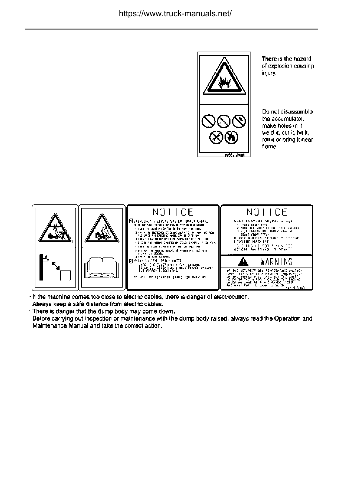
(5) Warning for handling suspension (09659-A0881)
SAFETY
(6) Warnings for electric wire
Warnings for crush hazard when inspection and maintenance
(569-93-82450)
2 - 8
Page 20
.
SAFETY
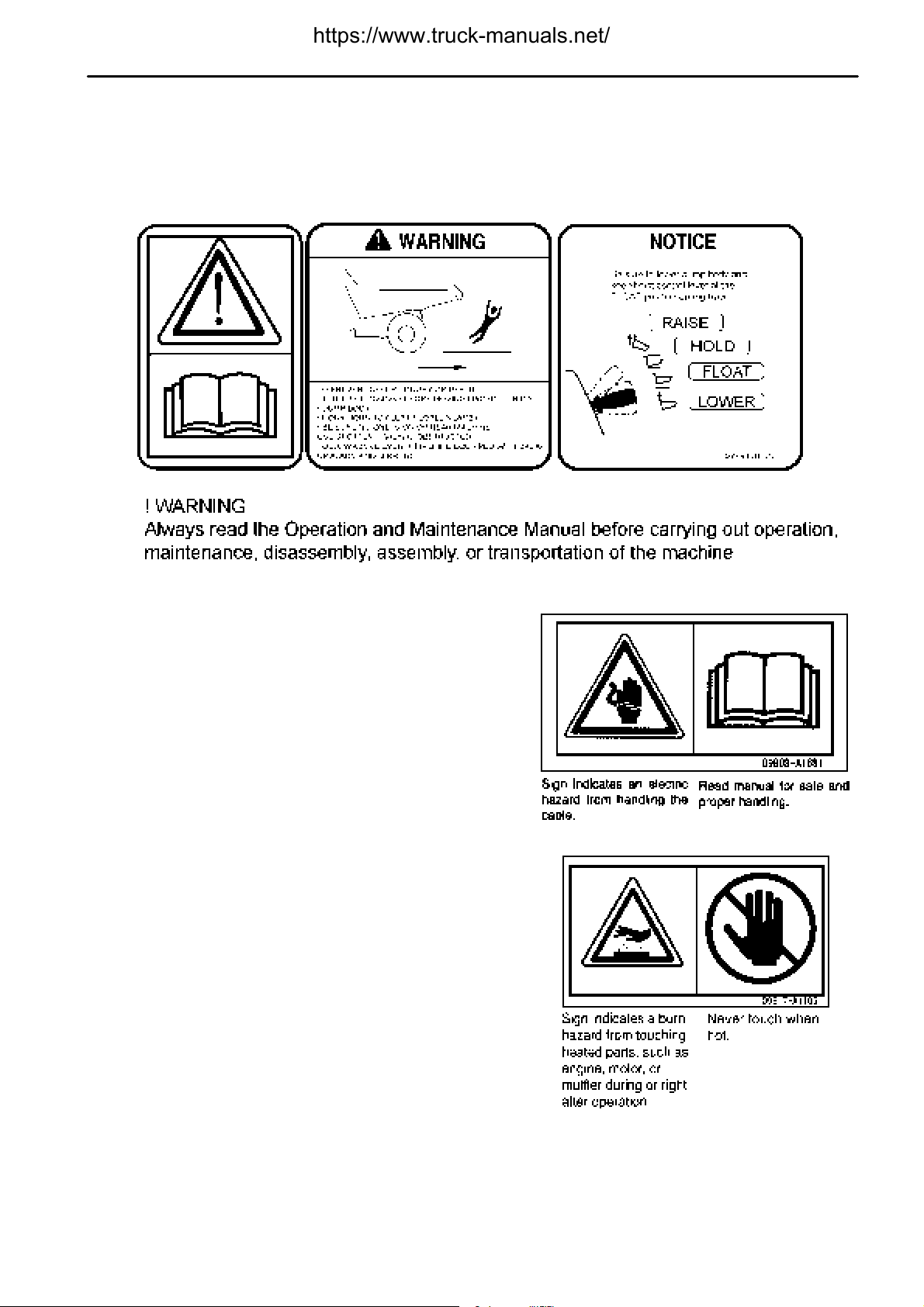
(7) Caution before starting
Caution when traveling in reverse
(569-93-81720)
SAFETY LABELS
(8) Caution when handling battery cable (09808-A1681)
(9) Exhaust pipe is hot! (09817-A1103)
2 - 9
Page 21
.
SAFETY
SAFETY LABELS
SAFETY LABELS
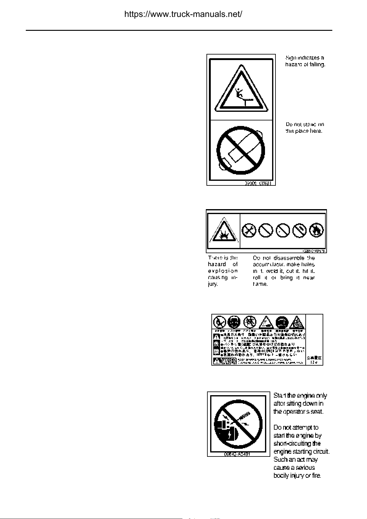
(10) Caution for avoiding falling down (09805-C0881)
SAFETY
(11) Precautions for handling accumulator (09659-A057B)
(12) Caution when gandling battery
This safety label is provided by the battery manufacturer.
(13) Jump start prohibited (09842-A0481)
This safety label is fixed to the engine starting motor.
2 - 10
Page 22
.
SAFETY
GENERAL PRECAUTIONS COMMON TO OPERATION AND MAINTENANCE
GENERAL PRECAUTIONS COMMON TO OPERATION AND
MAINTENANCE
Mistakes in operation, inspection, or maintenance may result in serious personal injury or death. Before carrying
out operation, inspection, or maintenance, always read this manual and the safety labels on the machine carefully
and obey the warnings.
PRECAUTIONS BEFORE STARTING OPERATION
ENSURING SAFE OPERATION
Only trained and authorized personnel can operate and maintain the machine.
Follow all safety, precautions, and instructions in this manual when operating or performing inspection or
maintenance on the machine.
If you are not feeling well, or if you are under the influence of alcohol or medication, your ability to safely operate
or repair your machine may be severely impaired, putting yourself and everyone else on your job site in danger.
When working with another operator or with the person on the worksite traffic duty, discuss the content of the
operation beforehand and use the determined signals when carrying out the operation.
UNDERSTANDING THE MACHINE
Before operating the machine, read this manual thoroughly. If there are any places in this manual that you do not
understand, ask the person in charge of safety to give an explanation.
PREPARATIONS FOR SAFE OPERATION
PRECAUTIONS REGARDING SAFETY-RELATED EQUIPMENT
Be sure that all guards, covers and mirrors are in their proper position. Have guards and covers repaired
immediately if they are damaged.
Understand the method of use of safety features and use them properly.
Never remove any safety features. Always keep them in good operating condition.
INSPECTING MACHINE
Check the machine before starting operations. If any abnormalityis found, do not operate the machine until repairs
of the problem location have been completed.
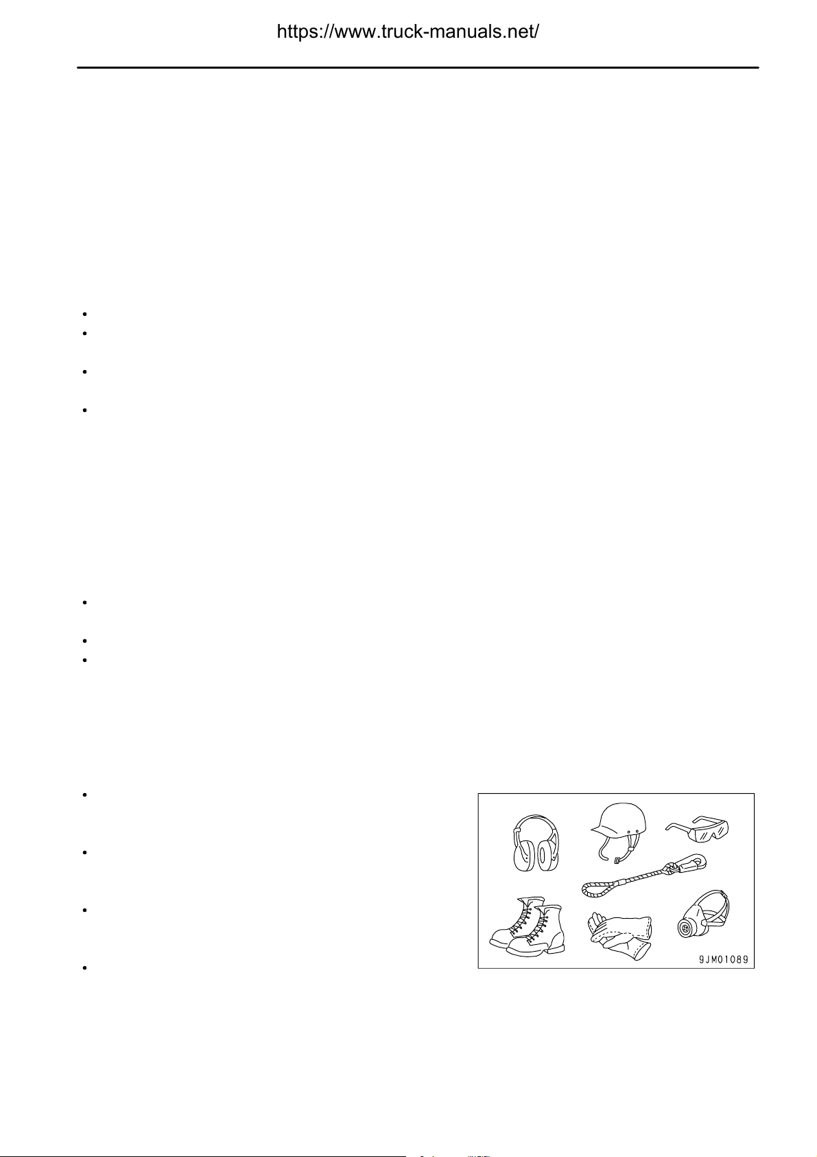
WEAR WELL-FITTING CLOTHES AND PROTECTIVE EQUIPMENT
Do not wear loose clothes or any accessories. If these catch on
the control levers or protruding parts, there is danger that it may
cause the machine to move unexpectedly.
Always wear a hard hat and safety shoes. If the nature of the
work requires it, wear safety glasses, mask, gloves, ear plugs,
and safety belt when operating or maintaining the machine.
If you have long hair and it hangs out from your hard hat, there
is a hazard that it may get caught up in the machine, so tie your
hair up and be careful not to let it get caught.
Check that all protective equipment functions properly before
using it.
2 - 11
Page 23
.
GENERAL PRECAUTIONS COMMON TO OPERATION AND MAINTENANCE
KEEP MACHINE CLEAN
If you get on or off the machine or carry out inspection and maintenance when the machine is dirty with mud or
oil, there is a hazard that you will slip and fall. Wipeoff any mud or oil from the machine. Always keep the machine
clean.
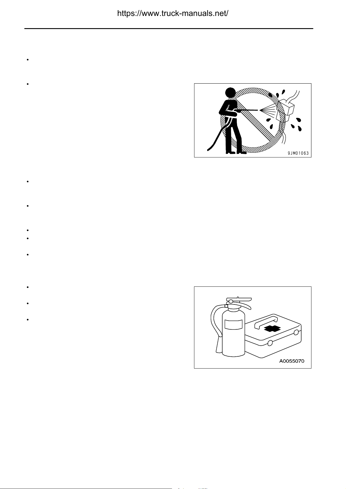
If water gets into the electrical system, there is a hazard that it
will cause malfunctions or misoperation. If there is any
misoperation, there is danger that the machine may move
unexpectedly and cause serious personal injury or death. When
washing the machine with water or steam, do not allow the water
or steam to come into direct contact with electrical components.
SAFETY
PRECAUTIONS INSIDE OPERATOR'S COMPARTMENT
When entering the operator's compartment, always remove all mud and oil from the soles of your shoes.
If you operate the pedal with mud or oil affixed to your shoes, your foot may slip and this may cause a serious
accident.
Do not leave tools or a machine parts lying around inside the operator's compartment. If tools or parts get into the
control devices, it may obstruct operation and cause the machine to move unexpectedly, resulting in serious
personal injury or death.
Do not stick suction pads to the window glass. Suction pads act as a lens and may cause fire.
Do not use a cell phone when driving or operating the machine. This may lead to mistakes in operation, which
could cause serious personal injury or death.
Never bring any dangerous objects such as flammable or explosive items into the operator's compartment.
PROVIDE FIRE EXTINGUISHER AND FIRST AID KIT
Always follow the precautions below to prepare for action if any injury or fire should occur.
Be sure that fire extinguishers have been provided and read the
labels to ensure that you know how to use them in emergencies.
Carry out periodic inspection and maintenance to ensure that
the fire extinguisher can always be used.
Provide a first aid kit in the storage point. Carry out periodic
checks and add to the contents if necessary.
IF ANY PROBLEM IS FOUND
If you find any problems in the machine during operation or maintenance (noise, vibration, smell, incorrect gauges,
smoke, oil leakage, etc., or any abnormal display on the warning devices or monitor), report to the person in charge
and have the necessary action taken. Do not operate the machine until the problem has been corrected.
2 - 12
Page 24
.
SAFETY
GENERAL PRECAUTIONS COMMON TO OPERATION AND MAINTENANCE
FIRE PREVENTION
ACTION IF FIRE OCCURS
Turn the start switch OFF to stop the engine.
Use the handrails and steps to get off the machine.
Do not jump off the machine. There is the danger of falling and suffering serious injury.
PRECAUTIONS TO PREVENT FIRE
Fire caused by fuel, oil, antifreeze, or window washer fluid
Do not bring any flame or fire close to flammable substances
such as fuel, oil, antifreeze, or window washer fluid. There is
danger that they may catch fire. To prevent fire, always observe
the following:
Do not smoke or use any flame near fuel or other flammable
substances.
Stop the engine before adding fuel.
Do not leave the machine when adding fuel or oil.
Tighten all fuel and oil caps securely.
Be careful not to spill fuel on overheated surfaces or on parts
of the electrical system.
After adding fuel or oil, wipe up any spilled fuel or oil.
Put greasy rags and other flammable materials into a safe
container to maintain safety at the workplace.
When washing parts with oil,use a non-flammableoil. Do not
use diesel oil or gasoline. There is danger that they may
catch fire.
Do not weld or use a cutting torch to cut any pipes or tubes
that contain flammable liquids.
Determine well-ventilated areas for storing oil and fuel. Keep
the oil and fuel in the determined place and do not allow
unauthorized persons to enter.
When carrying out grinding or welding work on the machine,
move any flammable materials to a safe place before
starting.
Fire caused by accumulation of flammable material.
Remove any dry leaves, chips, pieces of paper, coal dust, or any other flammable materials accumulated or
affixed around the engine, exhaust manifold, muffler, or battery, or inside the undercovers.
Fire coming from electric wiring
Short circuits in the electrical system can cause fire. To prevent fire, always observe the following.
Keep all electric wiring connections clean and securely tightened.
Check the wiring every day for looseness or damage. Tighten any loose connectors or wiring clamps. Repair
or replace any damaged wiring.
Fire coming from piping
Check that all the hose and tube clamps, guards, and cushions are securely fixed in position.
If they are loose, they may vibrateduring operation and rub against other parts. There is dangerthat this may lead
to damage to the hoses and cause high-pressure oil to spurt out, leading to fire, serious personal injury or death.
2 - 13
Page 25
.
GENERAL PRECAUTIONS COMMON TO OPERATION AND MAINTENANCE
Explosion caused by lighting equipment
When checking fuel, oil, battery electrolyte, or coolant, always use lighting with anti-explosion specifications.
SAFETY
PRECAUTIONS WHEN GETTING ON OR OFF MACHINE
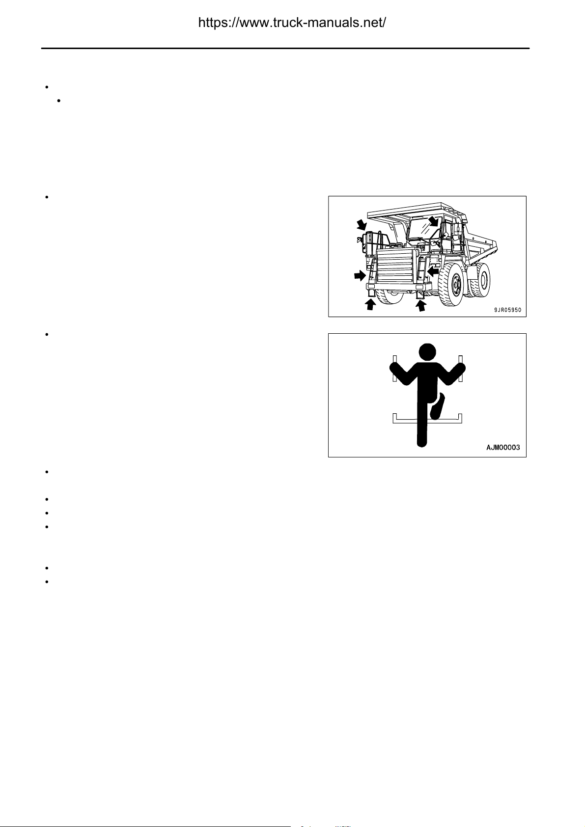
USE HANDRAILS AND STEPS WHEN GETTING ON OR OFF MACHINE
To prevent personal injury caused by slipping or falling off the machine, always do as follows.
Use the handrails and steps marked by arrows in the diagram on
the right when getting on or off the machine.
Always face the machine and maintain at least three-point
contact (both feet and one hand, or both hands and one foot)
with the handrail and steps to ensure that you support yourself.
Before getting on or off the machine, check the handrails and steps, and if there is any oil, grease, or mud on
them, wipe it off immediately. In addition, repair any damage and tighten any loose bolts.
Do not grip the control levers when getting on or off the machine.
Never climb on the engine hood or covers where there are no non-slip pads.
Do not get on or off the machine while holding tools in your hand.
NO JUMPING ON OR OFF MACHINE
Never jump on or off the machine. Never get on or off a moving machine.
If the machine starts to move when there is no operator on the machine, do not jump on to the machine and try
to stop it.
NO PEOPLE ON DUMP BODY
Never let anyone ride in the dump body. There is danger of falling and suffering serious personal injury.
2 - 14
Page 26

.
SAFETY
PRECAUTIONS WHEN STANDING UP FROM OPERATOR'S SEAT
Before standing up from the operator's seat to adjust the operator's
seat, always lower the dump body completely, lock with dump
lever lock knob (1), set gear shift lever (2) to the N position, set
parking brake switch (3) to the PARKING position, then stop the
engine.
If this is not done and the control levers are touched by mistake,
there is danger that the machine may suddenly move and cause
serious personal injury or death.
GENERAL PRECAUTIONS COMMON TO OPERATION AND MAINTENANCE
PRECAUTIONS WHEN LEAVING MACHINE
If the proper procedures are not taken when parking the machine, the machine may suddenly move off by itself, and
this may lead to serious personal injury or death. Always do the following.
When leaving the machine, always lower the dump body
completely, lock with dump lever lock knob (1), set gear shift
lever (2) to the N position, set parking brake switch (3) to the
PARKING position, then stop the engine.
Lock all places and always take the key with you and leave it in
the specified location.
EMERGENCY EXIT FROM OPERATOR'S CAB
Machines equipped with a cab have doors on the left and right sides. If the door on the one side does not open,
escape from the door on the other side.
2 - 15
Page 27
.
GENERAL PRECAUTIONS COMMON TO OPERATION AND MAINTENANCE
SAFETY
DO NOT GET CAUGHT IN DUMP BODY
The clearance in the area around the dump body changes
according to the movement of the dump body. If you are caught,
there is danger that you will suffer serious injury or death.
Do not allow anyone near any of the rotating or telescopic parts.
PRECAUTIONS RELATED TO PROTECTIVE STRUCTURES
The operator's compartment is equipped with a structure (ROPS,
FOPS) to protect the operator by absorbing the impact energy. If
the machine weight (mass) exceeds the certified value (shown on
the ROLL-OVER PROTECTIVE STRUCTURE (ROPS)
CERTIFICATION plate), ROPS will not be able to fulfill its function.
Do not increase machine weight beyond the certified value by
modifying the machine or by installing attachments to the machine.
Also, if the function of the protective equipment is impeded, the
protective equipment will not be able to protect the operator, and
the operator may suffer injury or death. Always observe the
following.
If the machine is equipped with a protective structure, do not remove the protective structure and carry out
operations without it.
If the protective structure is welded, or holes are drilled in it, or it is modified in any other way, its strength may
drop. Consult your Komatsu distributor before carrying out any modifications.
If the protective structure is damaged or deformed by falling objects or by rolling over, its strength will be reduced
and it will not be able to fulfill its function properly. In such cases, always contact your Komatsu distributor for
advice on the method of repair.
Even if the protective structure is installed, always fasten your seat belt properly when operating the machine.
If you do not fasten your seatbelt properly, it cannot display its effect.
UNAUTHORIZED MODIFICATION
Komatsu will not be responsible for any injuries, accidents, product failures or other property damages resulting
from modifications made without authorization from Komatsu.
Any modification made without authorization from Komatsu can create hazards. Before making a modification,
consult your Komatsu distributor.
Do not try to increase the capacity of the dump body or make any other modifications. Such modifications will
cause a drop in the braking efficiency, the balance of the machine will become poor, and this may lead to an
unexpected accident.
2 - 16
Page 28
.
SAFETY
GENERAL PRECAUTIONS COMMON TO OPERATION AND MAINTENANCE
PRECAUTIONS RELATED TO ATTACHMENTS AND OPTIONS
Any injuries, accidents, product failures or other property damages resulting from the use of unauthorized
attachments or parts will not be the responsibility of Komatsu.
When installing optional parts or attachments, there may be problems with safety or legal restrictions. Therefore
contact your Komatsu distributor for advice.
When installing and using optional attachments, read the instruction manual for the attachment, and the general
information related to attachments in this manual.
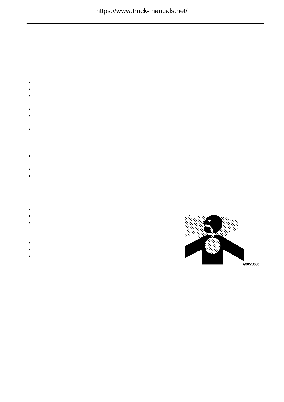
PRECAUTIONS WHEN RUNNING ENGINE INSIDE BUILDING
The engine exhaust gas contains substances that may damage
your health or even cause death. Start or operate the engine in a
place where there is good ventilation. If the engine or machine
must be operated inside a building or under ground, where the
ventilation is poor, take steps to ensure that the engine exhaust
gas is removed and that ample fresh air is brought in.
2 - 17
Page 29
.
PRECAUTIONS FOR OPERATION
SAFETY
PRECAUTIONS FOR OPERATION
PRECAUTIONS FOR JOBSITE
INVESTIGATE AND CONFIRM JOBSITE CONDITIONS
On the jobsite, there are various hidden dangers that may lead to personal injury or death. Before starting
operations, always check the following to confirm that there is no danger on the jobsite.
Check the terrain and condition of the ground at the worksite, and determine the safest method of operation. Do
not operate where there is a hazard of landslides or falling rocks.
Take necessary measures to prevent any unauthorized person from entering the operating area.
When traveling or operating in water or on soft ground, check the water depth, speed of the current, bedrock, and
shape of the ground beforehand and avoid any place that will obstruct travel.
Maintain the travel path on the jobsite so that there is no obstruction to travel operations.
WORKING ON LOOSE GROUND
Avoid traveling or operating your machine too close to the edge of cliffs, overhangs, and deep ditches. The
ground may be weak in such areas. If the ground should collapse under the weight or vibration of the machine,
there is a hazard that the machine may fall or tip over. Remember that the soil after heavy rain or blasting or after
earthquakes is weak in these areas.
When working on embankments or near excavated ditches, there is a hazard that the weight and vibration of the
machine will cause the soil to collapse. Before starting operations, take steps to ensure that the ground is safe
and to prevent the machine from rolling over or falling.
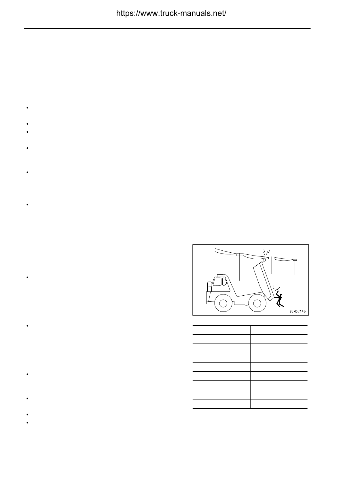
DO NOT GO CLOSE TO HIGH-VOLTAGE CABLES
Do not travel or operate the machine near electric cables. There is
a hazard of electric shock, which may cause serious personal
injury or death. On jobsites where the machine may go close to
electric cables, always do as follows.
Before starting work near electric cables, inform the local power
company of the work to be performed, and ask them to take the
necessary action.
Even going close to high-voltage cables can cause electric
shock, which may cause serious burns or even death. Always
maintain a safe distance (see the table on the right) between the
machine and the electric cable. Check with the local power
company about safe operating procedure before starting
operations.
To prepare for any possible emergencies, wear rubber shoes
and gloves. Lay a rubber sheet on top of the seat, and be careful
not to touch the chassis with any exposed part of your body.
Use a signalman to give warning if the machine approaches too
close to the electric cables.
When carrying out operations near high voltage cables, do not let anyone near the machine.
If the machine should come too close or touch the electric cable, to prevent electric shock, the operator should
not leave the operator's compartment until it has been confirmed that the electricity has been shut off.
Also, do not let anyone near the machine.
Voltage of Cables Safety Distance
100V - 200V Over 2 m (7 ft)
6,600V Over 2 m (7 ft)
22,000V Over 3 m (10 ft)
66,000V Over 4 m (14 ft)
154,000V Over 5 m (17 ft)
187,000V Over 6 m (20 ft)
275,000V Over 7 m (23 ft)
500,000V Over 11 m (36 ft)
2 - 18
Page 30
.
SAFETY
ENSURE GOOD VISIBILITY
This machine is equipped with mirrors to ensure good visibility, but even then there are places that cannot be seen
from the operator's seat, so be careful when operating.
When traveling or carrying out operations in places with poor visibility, it is impossible to check for obstacles in the
area around the machine and to check the condition of the jobsite. This leads to danger of serious personal injury
or death. When traveling or carrying out operations in places with poor visibility, always observe the following.
Position a signalman if there are areas where the visibility is not good.
Only one signalman should give signals.
When working in dark places, turn on the working lamp and front lamps installed to the machine, and set up
additional lighting in the work area if necessary.
Stop operations if the visibility is poor, such as in mist, snow, rain, or dust.
When checking the mirrors installed to the machine, remove all dirt and adjust the angle of the mirror to ensure
good visibility.
If the machine is equipped with cameras, clean off any dirt from the lens and make sure that the camera gives
a clear view.
PRECAUTIONS FOR OPERATION
CHECKING SIGNS AND SIGNALMAN'S SIGNALS
Set up signs to inform of road shoulders and soft ground. If the visibility is not good, position a signalman if
necessary. Operators should pay careful attention to the signs and follow the instructions from the signalman.
Only one signalman should give signals.
Make sure that all workers understand the meaning of all signals and signs before starting work.
BEWARE OF ASBESTOS DUST
Asbestos dust in the air can cause lung cancer if it is inhaled. There is danger of inhaling asbestos when working
on jobsites handling demolition work or work handling industrial waste. Always observe the following.
Spray water to keep down the dust.
Do not use compressed air.
If there is danger that there may be asbestos dust in the air,
always operate the machine from an upwind position, and make
sure that all workers operate on the upwind side.
All workers should use anti-dust masks.
Do not allow other persons to approach during the operation.
Always observe the rules and regulations for the work site and
environmental standards.
This machine does not use asbestos, but there is a danger that imitation parts may contain asbestos, so always use
genuine Komatsu parts.
2 - 19
Page 31

.
PRECAUTIONS FOR OPERATION
SAFETY
STARTING ENGINE
USE WARNING TAGS
If there is any "DANGER! Do NOT operate!" warning tag displayed,
it means that someone is carrying out inspection and maintenance
of the machine. If the warning sign is ignored and the machine is
operated, there is danger that the person carrying out inspection or
maintenance may be caught in the rotating parts or moving parts
and suffer serious personal injury or death. Do not start the engine
or touch the levers.
CHECKS BEFORE STARTING ENGINE
Carry out the following checks before starting the engine at the beginning of the day's work to ensure that there is
no problem with the operation of the machine. If this inspection is not carried out properly problems may occur with
the operation of the machine, and there is danger that this may lead to serious personal injury or death.
Remove all dirt from the surface of the window glass to ensure a good view.
Carry out the "WALK-AROUND CHECK (PAGE 3-70)".
Remove all dirt from the surface of the lens of the front lamps, working lamps, and rear combination lamp, and
check that they light up correctly.
Check the coolant level, fuel level, and oil level in engine oil pan, check for clogging of the air cleaner, and check
for damage to the electric wiring.
Check that there is no mud or dust accumulated around the movable partsof the accelerator pedal or brake pedal,
and check that the pedals work properly.
Adjust the operator's seat to a position where it is easy to carry out operations, and check that there is no damage
or wear to the seat belt or mounting clamps.
Check that the gauges work properly, check the angle of the mirrors, and check that the gear shift lever is at the
N position and that the dump control lever is at the HOLD position.
Before starting the engine, check that the lock knob of the dump control lever is at the LOCK position.
Adjust the mirrors so that the rear of the machine can be seen easily from the operator's seat. For details of the
method of adjusting, see "ADJUSTING MIRROR (PAGE 3-85)".
Check that there are no persons or obstacles above, below, or in the area around the machine.
Check that the parking brake switch is at the PARKING position.
2 - 20
Page 32

.
SAFETY
PRECAUTIONS WHEN STARTING ENGINE
Start and operate the machine only while seated.
When starting the engine, sound the horn as a warning.
If another person is allowed on the machine, that person may sit only in the assistant's seat.
Do not attempt to start the engine by short-circuiting the engine starting circuit. This may cause fire, serious
personal injury or death.
Check that the backup alarm (alarm buzzer when machine travels in reverse) works properly.
PRECAUTIONS IN COLD AREAS
Carry out the warming-up operation thoroughly. If the machine is not thoroughly warmed up before the control
levers are operated, the reaction of the machine will be slow, and this may lead to unexpected accidents.
If the battery electrolyte is frozen, do not charge the battery or start the engine with a different power source.
There is a hazard that this will ignite the battery and cause the battery to explode.
Before charging or starting the engine with a different power source, melt the battery electrolyte and check that
there is no leakage of electrolyte before starting.
PRECAUTIONS FOR OPERATION
STARTING WITH BOOSTER CABLES
If any mistake is made in the method of connecting the booster
cables, it may cause the battery to explode, so always do as
follows.
Always wear safety goggles and rubber gloves when starting
the engine with booster cable.
When connecting a normal machine to a problem machine with
booster cables, always use a normal machine with the same
battery voltage as the problem machine.
When starting with a booster cable, carry out the starting
operation with two workers (one worker sitting in the operator's
seat and the other working with the battery).
When starting from another machine, do not allow the two
machines to touch.
When connecting the booster cables, turn the starting switch to
the OFF position for both the normal machine and problem
machine. There is a hazard that the machine will move when the
power is connected.
Be sure to connect the positive (+) cable first when installing the
booster cables. Disconnect the negative (-) cable (ground side)
first when removing them.
When removing the booster cables, be careful not to let the
booster cable clips touch each other or to let the clips touch the
machine.
For details of the starting procedure when using booster cables,
see "STARTING ENGINE WITH BOOSTER CABLE (PAGE
3-135)" in the OPERATION section.
2 - 21
Page 33

.
PRECAUTIONS FOR OPERATION
SAFETY
OPERATION
CHECKS BEFORE OPERATION
If the checks before starting are not carried out properly, the machine will be unable to display its full performance,
and there is also danger that it may lead to serious personal injury or death.
When carrying out the checks, move the machine to a wide area where there are no obstructions, and pay careful
attention to the surrounding area. Do not allow anyone near the machine.
Always wear the seatbelt. There is danger that you may be
thrown out of the operator's seat and suffer serious injury when
the brakes are applied suddenly.
Check the operation of travel, steering and brake systems, and
dump body control system.
Check for any problem in the sound of the machine, vibration,
heat, smell, or gauges; check also that there is no leakage of oil
or fuel.
If any problem is found, carry out repairs immediately.
PRECAUTIONS WHEN TRAVELING IN FORWARD OR REVERSE
Lock the cab door and windows securely, both when they are open and when they are closed.
If another person is allowed on the machine, that person may sit only in the assistant's seat.
If there are any persons in the area around the machine, there
is danger that they may be hit or caught by the machine, and this
may lead to serious personal injury or death. Always observe
the following before traveling.
Always operate the machine only when seated.
Before moving off, check again that there is no person or
obstruction in the surrounding area.
Before moving, sound the horn to warn people in the
surrounding area.
Check that the backup alarm (alarm buzzer when machine
travels in reverse) works properly.
If there is an area to the rear of the machine which cannot be
seen, position a signalman.
Always be sure to carry out the above precautions even when the
machine is equipped with mirrors and cameras.
2 - 22
Page 34

.
SAFETY
PRECAUTIONS WHEN TRAVELING
Never turn the key in the starting switch to the OFF position. It is dangerous if the engine stops when the machine
is traveling, because the steering becomes heavy. There is danger that this will cause misoperation of the
steering wheel and may lead to serious personal injury or death. If the engine stops, depress the brake pedal
immediately to stop the machine.
When traveling or carrying out operations, always keep a safe distance from people, structures, or other
machines to avoid coming into contact with them.
Try to avoid having the machine climb over obstacles. If that is unavoidable, let the machine do that at a low
speed. Nonetheless avoid a big obstacle that greatly tilts the machine to the right or left, because in such a case
the machine can easily overturn sideways.
When traveling on rough ground, travel at low speed and avoid sudden changes in direction to prevent the
machine from turning over.
Do not load the dump body above the maximum payload. The brakes will lose their effect.
Lower the dump body, setting the dump lever at FLOAT position, then travel.
When passing over bridges or structures, check first that the structure is strong enough to support the weight of
the machine.
When operating in tunnels, underbridges, under electric wires, or other places where theheight is limited, operate
slowly and be extremely careful not to let the machine body or work equipment hit anything.
If you drive the machineat high speedcontinuously for a long time, the tires willoverheat and the internal pressure
will become abnormally high. This may cause the tires to burst. If a tire bursts, it produces a large destructive
force, and this may cause serious injury or death.
If you are going to travel continuously, please consult your Komatsu distributor.
When travelling, and particularly when travelling downhill, never set the gear shift lever to the Neutral position.
Always keep it in a speed range when travelling.
If the gear shift lever is at Neutral, it will be impossible to use the braking force of the engine and the steering
will become heavier. In addition, there will be insufficientcooling oil for the retarder,so there is danger that this
will result in overheating, which will lead to defective operation of the brakes.
The transmission and other parts of the power train may be damaged, and there is danger that this will lead
to serious injury or death.
PRECAUTIONS FOR OPERATION
TRAVELING ON SLOPES
To prevent the machine from tipping over or slipping to the side, always do as follows.
When traveling downhill, use the retarder brake to reduce speed. Do not turn the steering wheel suddenly.
Travel on grass, fallen leaves, or wet steel plates with low speed. Even with slight slopes there is a hazard that
the machine may slip.
If the engine should stop on a slope, apply the brakes fully and apply the parking brake also to stop the machine.
Do not shift gear while traveling downhill or travel downhill with the transmission in neutral.
It is dangerous if the engine has no braking effect. Always set the transmission to a lower gear before starting
to travel downhill.
PRECAUTIONS WHEN OPERATING
When using the machine, to prevent personal injury caused by damage to the work equipment or by the machine
overturning due to overloading, do not exceed the permitted performance of the machine or the maximum
permitted load for the structure of the machine.
When operating in tunnels, or under bridges or electric wires, or in other places where the height is limited,
operate slowly and be extremely careful not to let the dump body contact anything.
To prevent accidents caused by hitting other objects, always operate the machine at a speed which is safe for
operation, particular in confined spaces, indoors, and in places where there are other machines.
2 - 23
Page 35

.
PRECAUTIONS FOR OPERATION
PRECAUTIONS WHEN LOADING DUMP BODY
Do not load the dump body so that the load is on one side. Always carry out loading that the load is spread
uniformly.
Do not leave or return to the operator's seat while the dump body is being loaded.
PRECAUTIONS WHEN OPERATING DUMP BODY
Before starting the dumping operation, check to be sure there is no person or object behind the machine.
Stop the machine in the correct position, and check again that there is no person or object behind the machine.
Give the determined signal, then slowly operate the dump body.
If necessary, use blocks for the wheels or position a flagman.
Not carry out dumping operations on slopes. The machine stability will become poor and there is danger that it
may tip over.
Do not travel with the body raised.
Be careful when raising the dump body. When the dump body is raised, the center of gravity of the machine
changes continuously. If the ground is soft, this will affect the stability of the machine.
Take care particularly when dumping sticky material (wet clay, frozen material, etc.) on a soft ground. The stability
of the machine is reduced and there is danger that it may tip over.
SAFETY
TRAVELING ON SNOW-COVERED OR FROZEN SURFACES
Snow-covered or frozen surfaces are slippery, so be extremely careful when traveling or operating the machine,
and do not operate the levers suddenly. Even a slight slope may cause the machine to slip, so be particularly
careful when working on slopes.
With frozen ground surfaces, the ground becomes soft when the temperature rises, and this may cause the
machine to tip over or make it impossible for the machine to escape.
When traveling on snow-covered roads, always fit tire chains.
If the machine enters deep snow, there is a hazard that it may tip over or become buried in the snow. Be careful
not to leave the road shoulder or to get trapped in a snow drift.
Do not apply the brakes suddenly on snow-covered slopes. Reduce speed, use the braking force of the engine,
and pump the brakes (depress the brake pedal several times) to stop the machine.
Do not try to carry out dumping operations when the load inside the dump body is frozen. There is danger that
this may cause the machine to tip over.
2 - 24
Page 36

.
SAFETY
PARKING MACHINE
Park the machine on firm, level ground.
Select a place where there is no hazard of landslides, falling rocks, or flooding.
When leaving the machine, always lower the dump body
completely, lock with dump lever lock knob (1), set gear shift
lever (2) to the N position, set parking brake switch (3) to the
PARKING position, then stop the engine.
Always close the operator's cab door, and use the key to lock all
the equipment in order to prevent any unauthorized person from
moving the machine. Always remove the key, take it with you,
and leave it in the specified place.
PRECAUTIONS FOR OPERATION
If it is necessary to park the machine on a slope, set blocks
under the wheels to prevent the machine from moving.
2 - 25
Page 37

.
PRECAUTIONS FOR OPERATION
SAFETY
TRANSPORTATION
When the machine is transported on a trailer, there is danger of serious personal injury or death during
transportation. Always do as follows.
Always check the machine dimensions carefully. Depending on the attachments installed, the machine weight,
transportation height, and overall length may differ.
Check beforehand that all bridges and other structures on the transportationroute are strong enough to withstand
the combined weight of the transporter and the machine being transported.
The machine can be divided into parts for transportation, so when transporting the machine, please contact your
Komatsu distributor to have the work carried out.
For the procedure when transporting, see "TRANSPORTATION (PAGE 3-118)".
LOADING AND UNLOADING
When loading or unloading the machine, mistaken operation may
bring the hazard of the machine tipping over or falling, so particular
care is necessary. Always do as follows.
Perform loading and unloading on firm, level ground only.
Maintain a safe distance from the edge of the road or cliff.
Always use ramps of adequate strength. Be sure that the ramps
are wide, long, and thick enough to provide a safe loadingslope.
Take suitable steps to prevent the ramps from moving out of
position or coming off.
Be sure the ramp surface is clean and free of grease, oil, ice and
loose materials. Remove dirt from the tire of the machine. On
a rainy day, in particular, be extremely careful since the ramp
surface is slippery.
Run the engine at low idling and drive the machine slowly at low
speed.
Never correct your steering on the ramps. If necessary, drive off
the ramps, correct the direction, then enter the ramps again.
When loading or unloading to an embankment or platform, make sure that it has suitable width, strength, and
grade.
For machines equipped with a cab, always lock the door after loading the machine. If this is not done, the door
may open during transportation.
For details, see "TRANSPORTATION (PAGE 3-118)".
Blocks
(1)
Ramp
(2)
Width of ramps: Same width as tiers
(3)
Angle of ramps: Max. 15
(4)
Block
(5)
°
2 - 26
Page 38

.
SAFETY
PRECAUTIONS FOR OPERATION
TOWING
WHEN TOWING
Always use the correct towingequipment and towing method. Any mistake in the selectionof the wire ropeor towing
bar or in the method of towing a disabled machine may lead to serious personal injury or death.
For details of the procedure for towing, see the "METHOD OF TOWING MACHINE (PAGE 3-129)"
Always confirm that the wire rope or drawbar used for towing has ample strength for the weight of the machine
being towed.
Never use a wire rope which has cut strands (A), reduced
diameter (B), or kinks (C). There is danger that the rope may
break during the towing operation.
Always wear leather gloves when handling wire rope.
Never tow a machine on a slope.
During the towing operation, never stand between the towing
machine and the machine being towed.
2 - 27
Page 39

.
PRECAUTIONS FOR MAINTENANCE
SAFETY
PRECAUTIONS FOR MAINTENANCE
PRECAUTIONS BEFORE STARTING INSPECTION AND MAINTENANCE
DISPLAY WARNING TAG DURING INSPECTION AND MAINTENANCE
If there is any "DANGER! Do NOT operate!" warning tag displayed,
it means that someone is carrying out inspection and maintenance
of the machine. If the warning sign is ignored and the machine is
operated, there is danger that the person carrying out inspection or
maintenance may be caught in the rotating parts or moving parts
and suffer serious personal injury or death. Do not start the engine
or touch the levers.
If necessary, put up signs around the machine also.
Warning tag part number: 09963-A1640
When not using this warning tag, keep it in the toolbox.
If there is no toolbox, keep it in the pocket for the Operation and
Maintenance Manual
KEEP WORKPLACE CLEAN AND TIDY
Do not leave hammers or other tools lying around in the work place. Wipe up all grease, oil, or other substances
that will cause you to slip. Always keep the work place clean the tidy to enable you to carry out operations safely.
If the work place is not kept clean and tidy, there is the danger that you will trip, slip, or fall over and injure yourself.
SELECT SUITABLE PLACE FOR INSPECTION AND MAINTENANCE
Stop the machine on firm, level ground.
Select a place where there is no hazard of landslides, falling rocks, or flooding.
ONLY AUTHORIZED PERSONNEL
Do not allow any unauthorized personnel into the area when servicing the machine. If necessary, employ a guard.
APPOINT LEADER WHEN WORKING WITH OTHERS
When repairing the machine or when removing and installing the work equipment, appoint a leader and follow his
instructions during the operation.
2 - 28
Page 40

.
SAFETY
STOP ENGINE BEFORE CARRYING OUT INSPECTION AND MAINTENANCE
Always stop the machine before performing any inspection and
maintenance.
Lower the dump body completely, set dump lever (1) to the
HOLD position, lock with dump lever lock knob (2), then stop the
engine.
PRECAUTIONS FOR MAINTENANCE
Set parking brake switch (3) to the PARKING position to apply
the parking brake, then put blocks in front of and behind the tires
to prevent the machine from moving.
2 - 29
Page 41

.
PRECAUTIONS FOR MAINTENANCE
TWO WORKERS FOR MAINTENANCE WHEN ENGINE IS RUNNING
To prevent personal injury, do not carry out maintenance with the engine running. If maintenance must be carried
out with the engine running, carry out the operation with at least two workers and do as follows.
One worker must always sit in the operator's seat and be ready
to stop the engine at any time. All workers must maintain
contact with the other workers.
When carrying out operations near the fan, fan belt, or other
rotating parts, there is a hazard of being caught in the parts, so
be careful not to come close.
Never drop or insert tools or other objects into the fan, fan belt,
or other rotating parts. There is danger that they may contact
the rotating parts and break or be sent flying.
Lower the dump body completely, set dump lever (1) to the
HOLD position, lock with dump lever lock knob (2), and take
steps to prevent the dump body from moving.
SAFETY
Set parking brake switch (3) to the PARKING position to apply
the parking brake, then put blocks in front of and behind the tires
to prevent the machine from moving.
Do not touch any control levers. If any control lever must be
operated, give a signal to the other workers to warn them to
move to a safe place.
2 - 30
Page 42

.
SAFETY
INSTALLING, REMOVING, OR STORING ATTACHMENTS
Appoint a leader before starting removal or installation
operations for attachments.
Place attachments that have been removed from the machine in
a stable condition so that they do not fall. And take steps to
prevent unauthorized persons from entering the storage area.
PRECAUTIONS WHEN WORKING AT HIGH PLACES
When working at high places, use a step ladder or other stand to ensure that the work can be carried out safely.
PRECAUTIONS FOR MAINTENANCE
PRECAUTIONS WHEN WORKING UNDER MACHINE
When carrying out inspection with the dump body raised, always
set the dump control lever to the HOLD position, set the lock
knob to the LOCK position, then insert the body pivot pin. If the
body pivot pin is not inserted, the dump body may go down when
the dump control lever is operated, and catch or cause serious
injury or even death to the person carrying out the inspection.
Always carry out the operation to remove or insert the body pivot
pin with at least two workers. This operation is carried out with
the dump body raised, so if the dump body comes down during
the operation, it may lead to serious injury or even death.
For details, see "BODY PIVOT PIN (PAGE 3-44)".
Make sure the hoists or jacks you use are in good repair and strong enough to handle the weight of the
component. Never use jacks at places where the machine is damaged,bent, or twisted. Never usefrayed, twisted
or pinched wire rope. Never use bent or distorted hooks.
Never use concrete blocks for supports. They can collapse under even light loads.
PROPER TOOLS
Use only tools suited to the task and be sure to use the tools
correctly. Using damaged, deformed, or low quality tools, or
making improper use of the tools may cause serious personal
injury.
2 - 31
Page 43

.
PRECAUTIONS FOR MAINTENANCE
SAFETY
PRECAUTIONS FOR INSPECTION AND MAINTENANCE
PRECAUTIONS WHEN WELDING
Welding operations must always be carried out by a qualified welderand in a place equippedwith proper equipment.
There is a hazard of gas, fire, or electrocution when carrying out welding, so never allow any unqualified personnel
to carry out welding.
HANDLING BATTERY
Before inspecting or handling the battery, turn the key in the starting switch to the OFF position.
Danger of battery exploding
When the battery is being charged, flammable hydrogen gas is
generated and may explode. In addition, the battery electrolyte
includes dilute sulphuric acid. Any mistake in handling may
cause serious personal injury, explosion, or fire, so always
observe the following.
Do not use or charge the battery if the battery electrolyte is
below the LOWER LEVEL mark. This will cause explosion.
Always carry out periodic inspection of the battery electrolyte
level, and add distilled water (or commercially available
battery filler solution) to the UPPER LEVEL mark.
Do not smoke or bring any flame close to the battery.
Hydrogen gas is generated when the battery is being
charged, so remove the battery from the machine, take it to
a well-ventilated place, remove the battery caps, then carry
out the charging.
After charging, tighten the battery caps securely.
Danger from dilute sulphuric acid
When the battery is being charged, flammable hydrogen gas is
generated and may explode. In addition, the battery electrolyte
includes dilute sulphuric acid. Any mistake in handling may
cause serious personal injury, explosion, or fire, so always
observe the following.
When handling the battery, always wear protective goggles
and rubber gloves.
If battery electrolyte gets into your eyes, immediately wash
your eyes with large amounts of fresh water. After that, get
medical attention immediately.
If battery electrolyte gets on your clothes or skin, wash it off
immediately with large amounts of water.
Removing battery cables
Before repairing the electrical system or carrying out electric welding, turn the starting switch OFF. Wait for
approx. 1 minute, then remove the negative (-) battery cable to stop the flow of electricity.
2 - 32
Page 44

.
SAFETY
Danger of sparks
There is hazard that sparks will be generated, so always observe the following.
Do not let tools or other metal objects make any contact between the battery cables. Do not leave tools lying
around near the battery.
When removing the battery cables, remove the ground cable (negative (-) cable) first. When installing,
connect the positive (+) cable first, then connect the ground.
Tighten the battery cable terminals securely.
Secure the battery firmly in the specified position.
PRECAUTIONS WHEN USING HAMMER
When using a hammer, pins may fly out or metal particles may be
scattered. This may lead to serious personal injury or death.
Always do as follows.
If pins are hit with a hammer, there is a hazard that the metal
particles may fly out and injure people in the surrounding area.
Always make sure that no-one is in the surrounding area before
using the hammer.
If hard metal parts such as pins, or bearings are hit with a
hammer, there is a hazard that pieces might be scattered and
cause serious personal injury or death. Always wear safety
glasses and gloves.
If the pin is hit with strong force, there is a hazard that it may fly
out and injure people in the surrounding area. Do not allow
anyone to enter the surrounding area.
PRECAUTIONS FOR MAINTENANCE
PRECAUTIONS WITH HIGH-TEMPERATURE COOLANT
To prevent burns from boiling water or steam spurting out when
checking or draining the coolant, wait for the coolant to cool down
to a temperature where the radiator cap can be touched by hand.
Then loosen the cap slowly to release the pressure inside the
radiator, and remove the cap.
PRECAUTIONS WITH HIGH-TEMPERATURE OIL
To prevent burns from hot oil spurting out or from touching
high-temperature parts when checking or draining the oil, wait for
the oil to cool down to a temperature where the cap or plug can be
touched by hand. Then loosenthe cap orplug slowly torelease the
internal pressure and remove the cap or plug.
2 - 33
Page 45

.
PRECAUTIONS FOR MAINTENANCE
PRECAUTIONS WITH HIGH-PRESSURE OIL
The hydraulic system is always under internal pressure. In addition, the fuel piping is also under internal pressure
when the engine is running and immediately after the engine is stopped. When carrying out inspection or
replacement of the piping or hoses, check that the internal pressure in the circuit has been released. If this is not
done, it may lead to serious personal injury or death. Always do as follows.
Do not carry out inspection or replacement work with the circuit under pressure.
If there is any leakage from the piping or hoses, the surrounding area will be wet, so check for cracks in the piping
and hoses and for swelling in the hoses.
When carry out inspection, wear safety glasses and leather gloves.
There is a hazard that high-pressure oil leaking from small holes
may penetrate your skin or cause loss of sight if it contacts your
skin or eyes directly. If you are hit by a jet of high-pressure oil
and suffer injury to your skin or eyes, wash the place with clean
water, and consult a doctor immediately for medical attention.
SAFETY
PRECAUTIONS WITH HIGH-PRESSURE FUEL
When the engine is running, high-pressure is generated in the engine fuel piping. When carrying out inspection or
maintenance of the fuel piping system, stop the engine and wait for at least 30 seconds to allow the internal pressure
to go down before starting the operation.
HANDLING HIGH-PRESSURE HOSES AND PIPING
If oil or fuel leaks from high-pressure hoses or piping, it may cause fire or misoperation, and lead to serious
personal injury, or death. If the hose or piping mounts are loose or oil or fuel is found to be leaking from the mount,
stop operations and tighten to the specified torque.
If any damaged or deformed hoses or piping are found, please consult your Komatsu distributor.
Replace the hose if any of the following problems are found.
Damaged hose or deformed hydraulic fitting.
Frayed or cut covering or exposed reinforcement wire layer.
Covering swollen in places.
Twisted or crushed movable portion.
Foreign material embedded in covering.
NOISE
When carrying out maintenance of the engine and you are exposed to noise for longperiods of time, wear ear covers
or ear plugs while working.
If the noise from the machine is too loud, it may cause temporary or permanent hearing problems.
2 - 34
Page 46

.
SAFETY
HANDLING SUSPENSION CYLINDER, ACCUMULATOR, GAS SPRING
The suspension cylinders, accumulator, and gas springs are charged with high-pressure nitrogen gas. If any
mistake is made in handling, there is danger that it may cause an explosion or serious personal injury. To prevent
accidents, always do as follows.
Do not remove or disassemble unless necessary.
Do not bring it near flame or dispose of it in fire.
Do not make holes in it, weld it, or use a cutting torch.
Do not hit or roll the accumulator, or subject it to any impact.
Ask your Komatsu distributor when sealing gas into the cylinder
or replacing gas from it.
When disposing of the accumulator, the gas must be released.
Please contact your Komatsu distributor to have this work
performed.
PRECAUTIONS FOR MAINTENANCE
PRECAUTIONS WITH COMPRESSED AIR
When carrying out cleaning with compressed air, there is a hazard of seriouspersonal injury caused by flyingdust
or particles.
When using compressed air to clean the filter element or radiator, wear safety glasses, anti-dust mask, gloves,
and other protective equipment.
MAINTENANCE OF AIR CONDITIONER
If air conditioner refrigerant gets into your eyes, it may cause loss of sight; if it contacts your skin, it may cause
frostbite. Never loosen any parts of the cooling circuit.
DISPOSING OF WASTE MATERIALS
To prevent pollution, pay careful attention to the method of disposing of waste materials.
Always put oil drained from your machine in containers. Never
drain oil directly onto the ground or dump into the sewage
system, rivers, the sea, or lakes.
Obey appropriate laws and regulations when disposing of
harmful objects such as oil, fuel, coolant, solvent, filters, and
batteries.
METHOD OF SELECTING WINDOW WASHER FLUID
Use an ethyl alcohol base washer liquid.
Methyl alcohol base washer liquid may irritate your eyes, so do not use it.
2 - 35
Page 47

.
PRECAUTIONS FOR MAINTENANCE
PERIODIC REPLACEMENT OF SAFETY CRITICAL PARTS
For using the machine safely for an extended period of time, replace safety-critical parts like hoses and seat belts
periodically.
Replacement of safety-critical parts: See "PERIODIC REPLACEMENT OF SAFETY CRITICAL PARTS (PAGE
4-16)".
The material of these components naturallychanges over time,and repeated usecauses deterioration, wear, and
fatigue. As a result, there is a hazard that these components may fail and cause serious personal injury or death.
It is difficult to judge the remaining life of these components from external inspection or the feeling when
operating, so always replace them at the specified interval.
Replace or repair safety-critical parts if any defect is found, even when they have not reached the specified
replacement time.
SAFETY
2 - 36
Page 48

.
SAFETY
PRECAUTIONS FOR MAINTENANCE
TIRES
HANDLING TIRES
If tires or rims are handled mistakenly, there is danger that the tire
may explode or be damaged, or that the rim may fly off and cause
serious personal injury or death.
To maintain safety, always do as follows.
Maintenance, disassembly, repair, and assembly of the tires
and rims requires special equipment and special technology, so
always ask your Komatsu distributor to carry out these
operations.
Use only specified tires and inflate them to the specified
pressure.
Suitable inflation pressure : see HANDLING TIRES (PAGE
3-114).
When pumping up the tires, check that no other person is
standing near the tire, and install an air chuck with a clip that can
be secured to the air valve.
To prevent the tire inflation pressure from becoming too high,
measure the pressure from time to time with an air gauge while
pumping up the tire.
If the tire pressure goes down abnormally or the rim parts do not
fit the tire, there is a problem with the tire or rim parts. Always
contact your Komatsu distributor for repairs.
If the rim parts are not fitted properly when the tire is being
pumped up, there is danger that the rim parts may fly off, so set
up a protective fence around the tire, and do not stand directly
in front of the rim. Stand beside the tread when pumping up the
tire.
Do not adjust the tire inflation pressure immediately after traveling at high speed or carrying out operations under
heavy load.
Never carry out welding or light a fire near the tire.
Always release all pressure from a single tire or from both tires of a dual assembly prior to removing any rim
components.
Before removing the tire from the machine for repairs, remove the valve partially to release the air from the tire,
then remove the tire.
2 - 37
Page 49

.
PRECAUTIONS FOR MAINTENANCE
PRECAUTIONS WHEN STORING TIRES
Tires for construction equipment are extremely heavy, it may lead
to serious personal injury or death. To maintain safety, always do
as follows.
As a basic rule, store the tires in a warehouse which
unauthorized persons cannot enter.
If the tires must be stored outside, always erect a fence and put
up "No Entry" signs.
Stand the tire on level ground, and block it securely so that it
cannot roll or fall over if any person should touch it.
Do not lay the tire on its side. This will deform the tire and cause
it to deteriorate.
If the tire should fall over, do not attempt to stop it. Get out of the
way quickly.
SAFETY
2 - 38
Page 50

.
3 - 1
Page 51

.
GENERAL VIEW
OPERATION
GENERAL VIEW
GENERAL VIEW OF MACHINE
This illustration shows the HD325-7.
Dump body
(1)
Rear wheel
(2)
Front wheel
(3)
3 - 2
(4)
Turn signal light
(5)
Head lamp
Page 52

.
OPERATION
GENERAL VIEW
GENERAL VIEW OF CONTROLS AND GAUGES
Dump lever
(1)
Lamp switch, Turn signal lever, Dimmer switch
(2)
Steering wheel
(3)
Machine monitor
(4)
Retarder control lever
(5)
Cigarette lighter
(6)
Gear shift lever
(7)
Parking brake switch
(8)
Accelerator pedal
(9)
Brake pedal
(10)
Secondary brake pedal
(11)
Dump lever lock knob
(12)
Auto retarder (ARSC) set lever (if equipped)
(13)
3 - 3
Page 53

.
GENERAL VIEW
Enlargement of machine monitor
OPERATION
Machine monitor mode selector switch 2
(1)
Machine monitor mode selector switch 1
(2)
Fog lamp switch
(3)
(4)
Yellow rotating lamp switch (if equipped)
(5)
Side lamp switch (if equipped)
(6)
Machine monitor bulb check switch
(7)
Night lighting dimmer switch
(8)
Hazard lamp switch
3 - 4
(if equipped)
Emergency steering switch
(9)
Power mode selector switch
(10)
AISS LOW switch
(11)
Front brake cut-off switch
(12)
Auto retarder (ARSC) switch (if equipped)
(13)
ASR switch (if equipped)
(14)
ABS switch (if equipped)
(15)
Page 54

.
OPERATION
EXPLANATION OF COMPONENTS
EXPLANATION OF COMPONENTS
The following is an explanation of devices needed for operating the machine.
To perform suitable operations correctly and safely, it is important to completely understand methods of operating
the equipment, and the meanings of the displays.
MACHINE MONITOR
A: Character display
B: Caution items
C: Emergency stop items
NOTICE
When the engine starting switch is turned to the ON position before starting the engine, a system check is carried out for 3
seconds.
The central warning lamp lights up for 2 seconds, and then goes out.
The alarm buzzer sounds for 2 seconds, and then stops.
The monitor lamp lights up for 2 seconds and then goes out for 1 second.
The shift indicator displays 88 for 2 seconds and then goes out for 1 second.
After a 3-second system check, the meter starts to function.
The character display shows "KOMATSU" for 3 seconds.
If the lamps do not work, there is probably a failure or disconnection, so please contact your Komatsu distributor for
inspection.
When the starting switch is turned ON, if the shift lever is not at the neutral position, after completion of the system check, the
shift lever position pilot lamp and the central warning lamp will light up, and the alarm buzzer will continue to sound
intermittently. When this happens, if the shift lever is set at neutral, N is displayed, the central warning lamp goes out, and the
buzzer stops.
D: Meter display portion
E: Central warning lamp
3 - 5
Page 55

.
EXPLANATION OF COMPONENTS
Check central warning lamp, alarm buzzer, monitor lamps, and meters.
Before starting the engine, turn the starting switch to the ON
position, press machine monitor check bulb switch (1), and check
that there is no failure in the monitor lamps.
In addition to the gauges that function during the system check, the
meter display portion is also actuated. When this happens, the
character display shows the machine model and the software
version of the machine monitor.
The gauges that do not function have probably failed, so please
contact your Komatsu distributor for inspection.
OPERATION
3 - 6
Page 56

.
OPERATION
CHARACTER DISPLAY
EXPLANATION OF COMPONENTS
The character display can display the following items.
(4)
Service meter
(1)
Odometer
(2)
Reverse travel odometer
(3)
Normally, the service meter/odometer is displayed on the character display.
If the machine has failed, or if there has been excessive load on the machine, or if it is necessary to carry out
inspection and maintenance, an action code is displayed to recommend suitable action.
When the time for replacing the filter or changing the oil is reached, after completion of the system check with the
starting switch at the ON position, the maintenance monitor caution lamps flash or light up, and at the same time,
the filter or oil to be replaced is displayed.
NOTICE
Information regarding the failure of the machine or maintenance is displayed on the character display when the starting switch
is at the ON position, check the display to confirm that there is no problem before starting to travel.
Action code display
(5)
Filter, oil replacement time display
3 - 7
Page 57

.
EXPLANATION OF COMPONENTS
SERVICE METER
This meter (1) shows the total time that the machine has been
operating.
While the engine is running, the service meter advances even if the
machine is not moving.
The meter advances by 1 for every hour of operation, regardless of
the engine speed.
Even if the starting switch is at the OFF position, the service meter
will display as long as the top part () of machine monitor mode
selector switch 1 is being pressed.
NOTICE
When the starting switch is at the OFF position, if the service meter is
displayed even though the top () of machine monitor mode selector
switch 1 is not being pressed, there is probably a failure in the machine, so
please contact your Komatsu distributor for inspection.
OPERATION
ODOMETER
This meter (2) indicates the total distance traveled in kilometers.
Even when the starting switch is at the OFF position, while the top
() of machine monitor mode selector switch 1 is being pressed,
it indicates the total distance traveled.
NOTICE
When the starting switch is at the OFF position, if the total distance is
displayed even although the top () of machine monitor mode selector
switch 1 is not being pressed, there is probably a failure in the machine, so
please contact your Komatsu distributor for inspection.
REVERSE TRAVEL ODOMETER
This meter (3) indicates the total distance traveled in reverse in
kilometers.
For details of the method of displaying the total distance traveled
in reverse, see "OTHER FUNCTIONS OF MACHINE MONITOR
(PAGE 3-26)".
3 - 8
Page 58

.
OPERATION
ACTION CODE DISPLAY
EXPLANATION OF COMPONENTS
CAUTION
If action code E03 isdisplayed, stop the machine immediately. Then see "ACTIONCODE(PAGE 3-142)" and contact your Komatsu
distributor for repairs.
If the machine has failed, or if there has been excessive load on the machine, or if it is necessary to carry out
inspection and maintenance, an action code is displayed on this panel (4) to recommend suitable action.
If more than one failure occurs at the same time, the most important action code is displayed. The order of
importance, starting from the highest, is E03, E02, and E01. If failures of equal importance occur at the same time,
the latest one is displayed.
When action codes E02 or E03 occur, the alarm buzzer sounds intermittently and the central warning lamp lights
up.
E03: When this code is displayed, stop the machine immediately,
check the failure code, and contact your Komatsu distributor
for repairs.
REMARK
The top line of the character display displays "E03" and the
bottom line displays "CHECK RIGHT NOW" and "CALL" in turn
for 3 seconds each.
The telephone number is displayed on the right of the "CALL"
display. If the telephone number has not been set, there is a
blank. For details of the method of setting the telephone
number, see "INPUT METHOD FOR TELEPHONE NUMBER
(PAGE 3-29)".
E02: If overrun related information is displayed, reduce the engine
speed and the speed of the machine while continuing
operations.
If the overheat related display is given, stop the machine and
run the engine under no load at a mid-range speed.
If an action code is still displayed after doing this, check the
failure code and contact your Komatsu distributor for repairs.
REMARK
The top line of the character display displays "E02" and the bottom
line displays the condition of the machine related to overrun or
overheat.
3 - 9
Page 59

.
OPERATION
EXPLANATION OF COMPONENTS
EXPLANATION OF COMPONENTS
E01: If maintenance location is displayed and the maintenance
caution lamp lights up, carry out inspection and maintenance
of the displayed item after the completion of operations or
when the shift changes.
If "MAINTENANCE" is displayed together with E01, check
the failure code and contact your Komatsu distributor for
repairs.
REMARK
"E01" is displayed on the top line of the character display and
"MAINTENANCE" or the part of the machine requiring inspection,
filling of fluid, or replacement is displayed on the bottom line.
FILTER, OIL REPLACEMENT TIME DISPLAY
After completion of the system check, this display (5) shows for 30
seconds the filters and oil which are near the replacement interval.
The maintenance caution lamp also flashes or lights up at the
same time.
After replacing the filter or changing the oil, reset the replacement
interval. For details, see "RESET METHOD FOR FILTER, OIL
REPLACEMENT TIME (PAGE 3-27)".
OPERATION
REMARK
The top line of the character display shows the name and ID number of the item needing replacement. The line
at the bottom shows the remaining time until replacement and the total number of times the item has been
replaced.
After giving the display for 30 seconds, the display does not appear again until the starting switch is turned again
to the ON position.
If the action code is being displayed, the message in the diagram above is not displayed on the characterdisplay.
If there two or more items to be displayed, they are displayed every three seconds.
If there are more than 10 items to be displayed, all the items are displayed once each.
The display is given when the time reaches 30 hours before the filter and oil replacement interval.
When the replacement interval approaches, the maintenance caution lamp flashes, and if the replacement
interval has passed, the lamp lights up.
3 - 10
Page 60

.
OPERATION
Items for display of filter, oil replacement time
EXPLANATION OF COMPONENTS
Item
Fuel prefilter 500 FUEL P FILT 41
Engine oil filter 500 ENG FILT 02
Engine oil 500 ENG OIL 01
Transmission oil filter (Pump outlet port) 500 TM FILT 13
Fuel main filter 1000 FUEL FILT 03
Corrosion resistor 1000 CORR RES 06
Torque converter, transmission and rear
brake cooling oil
Brake oil filter 1000 BK OIL FILT 14
Brake cooling oil filter 1000 BK C FILT 16
Steering, hoist oil filter 2000 HYD FILT 04
Differential case oil 2000 DIFF OIL 11
Final drive oil 2000 FNL OIL 08
Steering, hoist oil 4000 HYD OIL 10
REMARK
See the section below for details of procedure for replacing the filter and oil.
Fuel prefilter
"REPLACE FUEL PREFILTER CARTRIDGE (PAGE 4-62)"
Engine oil filter
"CHANGE OIL IN ENGINE OIL PAN, REPLACE ENGINE OIL FILTER CARTRIDGE (PAGE 4-61)"
Engine oil
"CHANGE OIL IN ENGINE OIL PAN, REPLACE ENGINE OIL FILTER CARTRIDGE (PAGE 4-61)"
Transmission oil filter (Pump outlet port)
"REPLACE TRANSMISSION OIL FILTER ELEMENT (PAGE 4-64)"
Fuel main filter
"REPLACE FUEL MAIN FILTER CARTRIDGE (PAGE 4-67)"
Corrosion resistor
"REPLACE CORROSION RESISTOR CARTRIDGE (PAGE 4-69)"
Torque converter, transmission and rear brake cooling
"CHANGE OIL IN TRANSMISSION CASE, BRAKE SUB TANK, WASH STRAINER (PAGE 4-70)"
Brake oil filter
"REPLACE BRAKE OIL FILTER ELEMENT (PAGE 4-74)"
Brake cooling oil filter
"REPLACE TRANSMISSION AND REAR BRAKE COOLING OIL FILTER ELEMENT (PAGE 4-73)"
Steering, hoist oil filter
"REPLACE STEERING, HOIST OIL TANK FILTER ELEMENT (PAGE 4-79)"
Differential case oil
"CHANGE OIL IN DIFFERENTIAL CASE (PAGE 4-80)"
Final drive oil
"CHANGE OIL IN FINAL DRIVE CASE (PAGE 4-80)"
Steering, hosit oil
"CHANGE OIL IN STEERING, HOIST OIL TANK (PAGE 4-82)"
Replacement
interval
1000 TC/TM/BKOIL 24
Character display ID number
3 - 11
Page 61

.
EXPLANATION OF COMPONENTS
CAUTION ITEMS
OPERATION
CAUTION
If the monitor lights up during travel, inspect the location of the problem quickly and take the necessary action.
Emergency steering pilot lamp
Seat belt caution lamp
(1)
Parking brake pilot lamp
(2)
Dump body pilot lamp
(3)
SEAT BELT CAUTION LAMP
This monitor (1) lights up if the seat belt is not fastened.
There is danger when traveling, so always fasten your seat belt.
(4)
Fuel level caution lamp
(5)
Maintenance caution lamp
(6)
3 - 12
Page 62

.
OPERATION
PARKING BRAKE PILOT LAMP
This monitor (2) lights up when the parking brake is applied.
DUMP BODY PILOT LAMP
This monitor (3) lights up when the dump body is raised or the
dump body lever is at any position other than "FLOAT".
EXPLANATION OF COMPONENTS
EMERGENCY STEERING PILOT LAMP
This monitor (4) lights up when the emergency steering is
actuated.
(Machines equipped with auto emergency steering)
If any problem should occur in the steering oil pressure circuit when
the machine is traveling, the auto emergency steering is actuated
and the related lamp lights up.
FUEL LEVEL CAUTION LAMP
This monitor (5) lights up when the level of the fuel remaining in the
fuel tank goes below 60 liters (15.85 US gal).
If it lights up, check the fuel level and add fuel.
3 - 13
Page 63

.
EXPLANATION OF COMPONENTS
MAINTENANCE CAUTION LAMP
This monitor (6) lights up if any of the the following are applicable.
When it lights up, action code "E01" and the location needing
maintenance are displayed on the character display at the same
time, so carry out inspection, filling, or replacement.
Drop in engine oil level
Clogged engine oil filter
Clogged air cleaner
Clogged transmission oil filter
Drop in engine cooling water level
REMARK
In addition to the above, if the filter or oil replacement time is displayed on the character display, the lamp will flash
or light up.
OPERATION
3 - 14
Page 64

.
OPERATION
EMERGENCY STOP ITEM
EXPLANATION OF COMPONENTS
CAUTION
If the monitor lights up, stop operations immediately, then check the corresponding area and carry out the action.
If any problem is found in the emergency stop items, the alarm buzzer will sound intermittently, and the monitor for
the location of the problem and the central warning lamp will light up.
Engine water temperature caution lamp
(1)
Torque converter oil temperature caution lamp
(2)
Retarder oil temperature caution lamp
(3)
Battery charge circuit caution lamp
(4)
Steering oil temperature caution lamp
(5)
Engine oil pressure caution lamp
(6)
Brake oil pressure caution lamp
(7)
(accumulator oil pressure)
Tilt caution lamp
(8)
Machine monitor, option system caution lamp
(9)
Engine system caution lamp
(10)
Transmission system caution lamp
(11)
Retarder system caution lamp
(12)
3 - 15
Page 65

.
EXPLANATION OF COMPONENTS
ENGINE WATER TEMPERATURE CAUTION LAMP
This monitor (1) warns the operator that the engine coolant
temperature has risen.
When it lights up, "E02 ENGINE OVERHEAT" is displayed on the
character display at the same time, and the engine output is
automatically limited.
Run the engine under no load at a mid-range speed until the lamp
goes out.
TORQUE CONVERTER OIL TEMPERATURE CAUTION LAMP
This monitor (2) warns the operator that the torque converter oil
temperature has risen.
When it lights up, "E02 TC OVERHEAT" is displayed on the
character display at the same time, so stop the machine in a safe
place, set the shift lever to the N position, and run the engine under
no load at a mid-range speed until the lamp goes out.
OPERATION
RETARDER OIL TEMPERATURE CAUTION LAMP
This monitor (3) warns the operator that the brake oil temperature
has risen.
When it lights up, "E02 BRAKE OVERHEAT" is displayed on the
character display at the same time , so stop the machine in a safe
place, set the shift lever to the N position, and run the engine under
no load at a mid-range speed until the lamp goes out.
BATTERY CHARGE CIRCUIT CAUTION LAMP
This monitor (4) lights up when the engine is running to warn the
operator of a problem in the charging system.
When it lights up, "E03 CHECK RIGHT NOW" is displayed on the
character display at the same time, so stop the machine
immediately at a safe place, then stop the engine and check the
charging circuit.
3 - 16
Page 66

.
OPERATION
STEERING OIL TEMPERATURE CAUTION LAMP
This monitor (5) lights up to warn the operator that the steering oil
temperature has risen.
When it lights up, "E02 STRG OVERHEAT" is displayed on the
character display at the same time, so stop the machine in a safe
place, set the shift lever to the N position, and run the engine under
no load at a mid-range speed until the lamp goes out.
ENGINE OIL PRESSURE CAUTION LAMP
This monitor (6) lights up to warn the operator that the engine
lubricating oil pressure has dropped.
When it lights up, "E03 CHECK RIGHT NOW" is displayed on the
character display, and the engine output is automatically limited.
Stop the machine immediately at a safe place, then stop the engine
and carry out inspection.
EXPLANATION OF COMPONENTS
The lamp lights up if the engine lubricating oil pressure goes below
the specified value when the engine is running,
If the engine is not running, the lamp does not light up.
BRAKE OIL PRESSURE CAUTION LAMP
This monitor (7) lights up to warn the operator that the brake
accumulator oil pressure has dropped below the specified value.
The central warning lamp and alarm buzzer are not actuated when
the engine is stopped.
If the accumulator oil pressure is still lower than the specified value
30 seconds after the engine has been started, "E03 CHECK
RIGHT NOW" is displayed on the character display, so stop the
machine immediately at a safe place, then stop the engine and
carry out inspection.
TILT CAUTION LAMP
This monitor (8) lights up if the dump body has left its seat when the
rear frame of the machine has tilted beyond the safety range to the
left or right.
Lower the dump body and move the machine to a safe place where
the machine is stable.
3 - 17
Page 67

.
EXPLANATION OF COMPONENTS
MACHINE MONITOR, OPTION SYSTEM CAUTION LAMP
This monitor (9) lights up when a problem has been detected in the
machine monitor or in the system for an installed option.
When it lights up, "E03 CHECK RIGHT NOW" is displayed on the
character display at the same time, so stop the machine
immediately at a safe place, then stop the engine and carry out
inspection.
ENGINE SYSTEM CAUTION LAMP
This monitor (10) lights up when a problem has been detected in
the system controlled by the engine controller.
When it lights up, "E03 CHECK RIGHT NOW" is displayed on the
character display at the same time, so stop the machine
immediately at a safe place, then stop the engine and carry out
inspection.
OPERATION
TRANSMISSION SYSTEM CAUTION LAMP
This monitor (11) lights up when a problem has been detected in
the system controlled by the transmission controller.
When it lights up, "E03 CHECK RIGHT NOW" is displayed on the
character display at the same time, so stop the machine
immediately at a safe place, then stop the engine and carry out
inspection.
RETARDER SYSTEM CAUTION LAMP
This monitor (12) lights up when a problem has been detected in
the system controlled by the retarder controller.
When it lights up, "E03 CHECK RIGHT NOW" is displayed on the
character display at the same time, so stop the machine
immediately at a safe place, then stop the engine and carry out
inspection.
3 - 18
Page 68

.
OPERATION
METER DISPLAY PORTION
PILOT DISPLAY PORTION
When the starting switch is ON, the pilot display lights up when the display items are functioning.
EXPLANATION OF COMPONENTS
Shift indicator
Preheating pilot lamp
(1)
Retarder pilot lamp
(2)
Lockup pilot lamp
(3)
Head lamp high beam pilot lamp
(4)
Turn signal pilot lamp
(5)
ENGINE PRE-HEATING PILOT LAMP
This monitor (1) lights up when the electrical heater for pre-heating
the engine is being actuated. When the starting switch is turned to
the ON position in cold weather, the monitor lights up. It goes out
after 20 to 30 seconds to indicate that the pre-heating has been
completed.
(6)
Shift lever position pilot lamp
(7)
Power mode pilot lamp
(8)
Auto suspension mode pilot lamp (if equipped)
(9)
3 - 19
Page 69

.
EXPLANATION OF COMPONENTS
RETARDER PILOT LAMP
This monitor (2) lights up when the retarder control lever is pulled
and the retarder is actuated.
LOCKUP PILOT LAMP
This monitor (3) lights up when the torque converter lockup is
engaged and the transmission is shifted to direct drive.
OPERATION
HEAD LAMP HIGH BEAM PILOT LAMP
This monitor (4) lights up when the head lamps are set to high
beam.
TURN SIGNAL PILOT LAMP
This monitor (5) flashes at the same time as the turn signal lamp
flashes.
3 - 20
Page 70

.
OPERATION
SHIFT INDICATOR
This monitor (6) shows the transmission shift range (speed range).
SHIFT LEVER POSITION PILOT LAMP
This monitor (7) displays the position of the shift lever.
The letter or number for the speed range selected by the shift lever
lights up.
EXPLANATION OF COMPONENTS
POWER MODE PILOT LAMP
This monitor (8) displays the power mode.
When the mode is selected with the power mode selector switch,
either High Power (P) or Economy (E) lights up.
3 - 21
Page 71

.
EXPLANATION OF COMPONENTS
AUTO SUSPENSION MODE PILOT LAMP
(If equipped)
This monitor (9) displays the suspension mode, when the machine
is equipped with the suspension controller.
On machines equipped with an automatic suspension system, the
suspension system automatically switches the damping
characteristics of the suspension according to the size of the load,
use of the brake, operation of the steering, and operation of the
dump control.
Normally it is set to the soft mode when the dump truck is traveling
empty and to the medium mode when it is traveling loaded. When
the foot brake is operated or the machine is suddenly turned, or the
dump control is operated, the suspension mode is switched to
insure the stability of the machine to the front and rear, and left and
right.
OPERATION
H : Hard mode
M : Medium mode
S : Soft mode
3 - 22
Page 72

.
OPERATION
METERS
EXPLANATION OF COMPONENTS
Engine water temperature gauge
Speedometer
(1)
Engine tachometer
(2)
Fuel gauge
(3)
SPEEDOMETER
This meter (1) indicates the travel speed of the machine.
ENGINE TACHOMETER
This meter (2) shows the engine speed.
If the gauge indicator the red range during operations, the alarm
buzzer will sound and the central warning lamp will light up at the
same time, so reduce the engine speed and the machine travel
speed.
(4)
Torque converter oil temperature gauge
(5)
Retarder oil temperature gauge
(6)
3 - 23
Page 73

.
EXPLANATION OF COMPONENTS
FUEL GAUGE
This meter (3) shows the amount of fuel remaining in the fuel tank.
When the fuel level caution lamp lights up, it indicates that there is
less than 60 liters (15.85 US gal) of fuel remaining in the tank, so
check and add fuel.
ENGINE WATER TEMPERATURE GAUGE
This meter (4) indicates the engine water temperature.
It should be in the white range during operation.
If it is in the red range during operation, the alarm buzzer will sound
and the central warning lamp will light up at the same time. "E02
ENGINE OVERHEAT" is displayed on the character display, so
run at the engine under no load at a mid-range speed and wait until
the meter enters the white range.
If it is in the red range, the engine output is automatically limited.
OPERATION
TORQUE CONVERTER OIL TEMPERATURE GAUGE
This meter (5) indicates the torque converter oil temperature.
It should be in the white range during operation.
If it is in the red range during operation, the alarm buzzer will sound
and the central warning lamp will light up. "E02 TC OVERHEAT"
is displayed on the character display, so run the engine under no
load at a mid-rangespeed and wait until the meter enters the white
range.
RETARDER OIL TEMPERATURE GAUGE
This meter (6) indicates the retarder oil temperature.
It should be in the white range during operation.
If it is in the red range during operation, the alarm buzzer will sound
and the central warning lamp will light up at the same time. "E02
BRAKE OVERHEAT" is displayed on the character display, so
stop the machine in a safe place, set the shift lever to the N
position, run the engine under no load at a mid-range speed and
wait until the lamp goes out.
3 - 24
Page 74

.
OPERATION
CENTRAL WARNING LAMP
If the machine is in the following condition, this lamp will flash, and
at the same time, the alarm buzzer will sound intermittently.
When a problem has occurred in any of "EMERGENCY STOP
ITEM (PAGE 3-15)".
When action code "E02" or "E03" is displayed on the character
display.
If the parking brake is applied, but the shift lever is not at the N
position.
When the dump lever is not at the FLOAT position or the dump
body is raised and the shift lever is not at the N position.
When the engine tachometer indicates the red range.
EXPLANATION OF COMPONENTS
3 - 25
Page 75

.
EXPLANATION OF COMPONENTS
OPERATION
OTHER FUNCTIONS OF MACHINE MONITOR
DISPLAY METHOD FOR REVERSE TRAVEL ODOMETER
Use this when checking the total travel distance in reverse.
Check that the character display is showing the service meter/odometer, or the action code. If it is giving any
1.
other display, turn the starting switch OFF, then turn the starting switch to the ON position and wait for the above
display to be given.
Press the () of machine monitor mode selector switch 1. It
2.
displays the overall distance traveled in reverse.
When completing the operation, press () of machine monitor
3.
mode selector switch 1 or turn the starting switch OFF.
3 - 26
Page 76

.
OPERATION
RESET METHOD FOR FILTER, OIL REPLACEMENT TIME
The filter and oil replacement time is displayed on the character display, so if the filter and oil have been replaced,
reset the filter and oil change time.
1. Press the () of machine monitor mode selector switch 1, and display the reverse travel in odometer.
Press (>) or (<) of machine monitor mode selector switch 2 and
2.
display "MAINTENANCE MONITOR".
Press the () of machine monitor mode selector switch 1. It
3.
will change to the display in the diagram on the right.
The bottom line shows two items: the replacement time on the
left and the total number of times the item has been replaced
on the right.
Press (>) or (<) of machine monitor mode selector switch 2 and
4.
display the item to be reset.
EXPLANATION OF COMPONENTS
5. Press the () of machine monitor mode selector switch 1. It
will change to the display in the diagram on the right.
The top line shows [Reset] and [Item to be reset] in turn.
6. When resetting the replacement time, press (>) or (<) of
machine monitor mode selector switch 2, align the cursor with
"YES", then press () of machine monitor mode selector
switch 1. It will reset and returned to the previous screen.
To abandon, align the cursor with "NO", then press () of
machine monitor mode selector switch 1.
When resetting the replacement time for another item, carry out the procedure from Step 4. After completing,
7.
press () of machine monitor mode selector switch 1 twice or turn the starting switch OFF.
3 - 27
Page 77

.
EXPLANATION OF COMPONENTS
METHOD FOR SELECTING LANGUAGE
Use this when switching the language displayed on the character display.
1. Press the () of machine monitor mode selector switch 1 and display the reverse travel odometer.
Press (>) or (<) of machine monitor mode selector switch 2 and
2.
display "LANGUAGE".
Press the () of machine monitor mode selector switch 1. The
3.
presently selected language is displayed.
Press (>) or (<) of machine monitor mode selector switch 2 and
4.
select the language.
OPERATION
The available languages are English, Japanese, German, French,
Italian, Spanish, and Swedish.
When the () of machine monitor mode selector switch 1 is pressed, the language is set and the screen returns
5.
to the previous screen.
6. When completing the operation, press () of machine monitor mode selector switch 1 twice or turn the starting
switch OFF.
3 - 28
Page 78

.
OPERATION
INPUT METHOD FOR TELEPHONE NUMBER
When an error for action code "E03" occurs, it is possible to display the telephone number.
1. Press the () of machine monitor mode selector switch 1 and display the reverse travel odometer.
Press (>) or (<) of machine monitor mode selector switch 2 and
2.
display "TEL".
Press () of machine monitor mode selector switch 1. It will
3.
change to the display in the diagram on the right.
EXPLANATION OF COMPONENTS
Once the telephone number is input, the input number will be
displayed next time.
Up to 12 digits can be displayed for the telephone number.
4.
Input from the first digits.
The cursor is displayed at the input position. Press (>) or (<) of
machine monitor mode selector switch 2 and display "0 - 9 ".
To leave a blank, select "*".
When the input value is decided, press () of machine monitor
mode selector switch 1. The cursor will move to the next
position.
Repeat the procedure in Step 4 until the last digit. At the last digit, press () of machine monitor mode selector
5.
switch 1 to return to the previous screen.
If there is a mistake in the input or the input is to be stopped, press () of machine monitor mode selector switch
1 to return to the previous screen.
When completing the operation, press () of machine monitor mode selector switch 1 twice or turn the starting
6.
switch OFF.
3 - 29
Page 79

.
EXPLANATION OF COMPONENTS
OPERATION
SWITCHES
Starting switch
(1)
Lamp switch
(2)
Turn signal lever
Dimmer switch
Machine monitor bulb check switch
(3)
Hazard lamp switch
(4)
Night lighting dimmer switch
(5)
Power mode selector switch
(6)
Emergency steering switch
(7)
Parking brake switch
(8)
AISS LOW switch
(9)
Front brake cut-off switch
(10)
Fog lamp switch (if equipped)
(11)
Side lamp switch (if equipped)
(12)
Yellow rotating lamp switch (if equipped)
(13)
Power window switch (right) (if equipped)
(14)
Power window switch (left)
(15)
Machine monitor mode selector switch 1, 2
(16)
Cigarette lighter
(17)
Horn button
(18)
Wiper, window washer switch
(19)
Room lamp switch
(20)
3 - 30
Page 80

.
OPERATION
STARTING SWITCH
This switch (1) is used to start or stop the engine.
OFF position :
At this position, the starting switch key can be inserted or removed.
When the key is turned to this position, all the electric circuits are
switched off and the engine stops.
ON position :
In this position, electric current flows in the charging and lamp
circuits.
Keep the starting switch key at the ON position while the engine is
running.
When turning the starting switch ON or OFF, if the starting switch
is held at a position between ON and OFF, the controller may
detect this as a problem. If this happens, return the starting switch
to the OFF position, then operate it as usual to the ON position.
EXPLANATION OF COMPONENTS
In cold weather, if the starting switch is turned to the ON position, pre-heating is automatically started and the engine
pre-heating pilot lamp lights up. After the pre-heating is completed, the engine pre-heating pilot lamp goes out.
START position :
This is the position to startthe engine. Hold the key at this positionwhile cranking. Releasethe key immediately after
the engine has been started. The key will return to the ON position when released.
LAMP SWITCH
This switch (2) lights up the head lamps, side clearance lamps, tail
lamps, machine monitor lighting, and rear lamps.
Position (a): OFF
Position (b): Side clearance lamps, tail lamps, real lamps, and
machine monitor lighting light up
Position (c): Front lamps light up in addition to lamps at position (b)
The lamp switch can be operated regardless of the position of the
lever.
TURN SIGNAL LEVER
This lever (2) operates the turn signal lamp.
(a)Right turn: Push the lever forward
(b)Left turn: Push the lever back
When the lever is operated, the turn signal pilot lamp also flashes.
The lever is automatically returned when the steering wheel is
turned back. If the lever does not return, move it by hand.
3 - 31
Page 81

.
EXPLANATION OF COMPONENTS
DIMMER SWITCH
This switch (2) is used to switch the head lamps between high
beam and low beam.
Each time switch (2) is moved up in direction (a), the head lamps
switch between high beam and low beam. When the switch is
released, it automatically returns to its original position (b).
When the lamp switch is OFF, if the switch is operated in direction
(a), the head lamps light up at the high beam position.
MACHINE MONITOR BULB CHECK SWITCH
Turn the starting switch ON, press this switch (3) and check for any
blown bulbs.
OPERATION
HAZARD LAMP SWITCH
This switch (4) is used to make the left and right turn signal
indicators flash.
(a): OFF
(b): Turn signal lamp and turn signal pilot lamp flash
When working at night, the symbol inside the switch lights up
regardless of the selected position of the switch.
NIGHT LIGHTING DIMMER SWITCH
This switch (5) is used to adjust the brightness of the lighting inside
the machine monitor and the pilot lamp display. Turn it to the right
to make the display brighter; turn it to the left to make the display
dimmer.
3 - 32
Page 82

.
OPERATION
POWER MODE SELECTOR SWITCH
This switch (6) is used to switch the power mode. This makes it
possible to travel economically in a way suited to the operating
conditions.
If portion (a) of the switch is pressed, high-power mode pilot lamp
(P) lights up and the system is switched to the high-power mode.
If portion (b) of the switch is pressed, economy mode pilot lamp (E)
lights up and the system is switched to the economy mode.
(a): High power mode (general operations)
Normal standard operating conditions
(b): Economy mode (operations on flat ground)
Work with emphasis on fuel consumption, such as work on flat
ground where the maximum power is not needed
When working at night, the symbol inside the switch lights up regardless of the selected position of the switch.
EXPLANATION OF COMPONENTS
EMERGENCY STEERING SWITCH
This switch (7) is used to actuate the emergency steering pump.
When the switch is pressed, the emergency pump is actuated to
make it possible to operate the steering.
When the switch is ON, the pilot lamp (red) inside the switch and
the pilot lamp on the machine monitor light up.
The emergency steering pump can be used for a maximum of 90
seconds.
When the emergency steering is being used, keep thetravel speed
to a maximum of 5 km/h (3.1 MPH).
On machines equipped with auto emergency steering, the auto emergency steering is actuated automatically in the
following cases.
When the steering hydraulic pump fails
When the engine has stopped during operation
When the emergency steering is actuated, stop the machine promptly and perform inspection.
If the starting switch is at the ON position and the parking brake switch is at the TRAVEL position when the engine
is stopped, the automatic emergency steering is actuated after 1 second, so set the parking brake switch to the
PARKING position.
3 - 33
Page 83

.
EXPLANATION OF COMPONENTS
PARKING BRAKE SWITCH
OPERATION
WARNING
When parking or leaving the machine, always apply the parking brake.
This switch (8) is used to actuate and release the parking brake
valve.
(a): Parking
The parking brake is applied.
(b): Travel
The parking brake is released.
When the switch is set to the PARKING position, the parking brake
pilot lamp lights up.
When the switch is set to the PARKING position, if the shift lever
is at any position other than N, the central warning lamp will flash
and the alarm buzzer will sound.
If any problem occurs in the brake circuit and the pressure in the accumulator goes down, the secondary brake is
automatically applied.
For details of the method of releasingthe secondary brake, see "WHEN PARKING BRAKE HAS BEEN ACTUATED
IN EMERGENCY (PAGE 3-132)".
When working at night, the symbol inside the switch lights up regardless of the selected position of the switch.
REMARK
If the engine is stopped with the parking brake switch at TRAVEL or the parking brake is operated mistakenly to
TRAVEL while the engine is stopped, when the engine is started again, the parking brake is applied even though
the parking brake switch is at TRAVEL. In this case, after starting the engine, operate the parking brake switch to
PARKING and then back to TRAVEL to cancel the parking brake.
3 - 34
Page 84

.
OPERATION
AISS LOW SWITCH
Using this switch (9), it is possible to switch the AISS freely
between AUTO and LOW. Use each position as follows.
(a): AUTO position
For normal operations
(b): LOW position
When fine control of the machine is needed, such as when
putting it into a garage.
If the switch is at AUTO position:
If the parking brake or retarder brake are operated, the idle is automatically adjusted to low speed. When the
parking brake and retarder brake are released, the idle is automatically adjusted to high speed.
The water temperature is detected, and when it is at low temperature, the idle is automatically adjusted to high
speed to reduce the warming-up time.
EXPLANATION OF COMPONENTS
When working at night, the symbol inside the switch lights up regardless of the selected position of the switch.
FRONT BRAKE CUT-OFF SWITCH
WARNING
When traveling on icy roads, on snow, or on other slippery road
surfaces, set the front brake cut-off switch to the (b) position and travel
slowly at a safe speed.
If the front brake cut-off switch is set to the (a) position when traveling
on icy road, on snow, or on other slippery road surfaces, there is danger
that the steering will be impossible to control.
This switch (10) can be used to switch the braking method of according to the road surface conditions.
If the (b) portion of the switch is pressed, the front brake cut function is actuated, and the front wheel brakes are not
applied.
(a): When the brake pedal is depressed, the brakes are applied to both the front and rear wheels.
(b): When the brake pedal is depressed, the front brakes are not applied. The brakes are applied only to the rear
wheels.
REMARK
When the secondary brake is applied, the front and rear wheel brakes and the parking brakes are applied,
regardless of the position of the front brake OFF switch.
When working at night, the symbol inside the switch lights up regardless of the selected position of the switch.
3 - 35
Page 85

.
EXPLANATION OF COMPONENTS
FOG LAMP SWITCH
(If equipped)
This switch (11) is used to switch on the fog lamp.
(a): Fog lamp goes out
(b): Fog lamp lights up
When working at night, the symbol inside the switch lights up
regardless of the selected position of the switch.
SIDE LAMP SWITCH
(If equipped)
This switch (12) is used to switch on the side lamp.
OPERATION
(a): Side lamp goes out
(b): Side lamp lights up
When working at night, the symbol inside the switch lights up
regardless of the selected position of the switch.
YELLOW ROTATING LAMP SWITCH
(If equipped)
This switch (13) is used to switch the yellow rotating lamp on and
off. When the lamp is switched on, it lights up and rotates.
(a): Yellow rotating lamp goes out
(b): Yellow rotating lamp lights up
When working at night, the symbol inside the switch lights up
regardless of the selected position of the switch.
3 - 36
Page 86

.
OPERATION
POWER WINDOW SWITCH (RIGHT) (LEFT)
(The right power window is optional.)
EXPLANATION OF COMPONENTS
WARNING
When closing the window glass, be careful not to get anyone's hands or head caught.
There is danger of serious injury if anyone is caught in the window glass.
CAUTION
After fully opening or fully closing the window glass, do not keep the switch operated in the same direction.
This may cause failure of the power window.
Switches (14) and (15) are used to open and close the window
glass. The switches can only be used when the starting switch is
at the ON position.
(a): Glass goes down
(b): Glass goes up
When the glass reaches the top or bottom and stops, release the
switch.
MACHINE MONITOR MODE SELECTOR SWITCH 1, 2
This switch (16) is used to operate the character display.
CIGARETTE LIGHTER
This switch (17) is used to light cigarettes.
When the cigarette lighter is pushed in, it will return to its original
position after several seconds, then pull it out and use it to light
your cigarette.
3 - 37
Page 87

.
EXPLANATION OF COMPONENTS
HORN BUTTON
When the horn button (18) in the center of the steering wheel is
pressed, the horn will sound.
WIPER, WINDOW WASHER SWITCH
This switch (19) is used to operate the wiper for the front glass.
Using the wiper when the glass is dry will scratch the glass. Spray
with window washer fluid before actuating the wiper.
OPERATION
Front wiper
Position (a) (OFF): Stopped
Position (b) (INT): Wiper moves once every 4 - 7 seconds
Position (c) (LOW): Wiper moves at low speed
Position (d) (Hi): Wiper moves at high speed
When the button (A) at the tip of the switch is pressed, washer fluid
is sprayed out.
Do not keep the button pressed for more than 10 seconds.
ROOM LAMP SWITCH
The switch (20) is used to turn the room lamp ON and OFF.
Position (a): OFF
Position (b): Lights up when the door opens
Position (c): Lights up
REMARK
The room lamp lights up even when the main switch is OFF, so
when leaving the operator's seat, set the switch to position (a)
or (b).
When carrying out operations with the door fully opened, set the
switch to position (a) (OFF).
3 - 38
Page 88

.
OPERATION
EXPLANATION OF COMPONENTS
CONTROL LEVERS AND PEDALS
Brake pedal
(1)
Accelerator pedal
(2)
Gear shift lever
(3)
Dump lever
(4)
BRAKE PEDAL
This pedal (1) is used to apply the wheel brakes.
Retarder control lever
(5)
Dump lever lock knob
(6)
Secondary barke pedal
(7)
3 - 39
Page 89

.
EXPLANATION OF COMPONENTS
ACCELERATOR PEDAL
This pedal (2) is used to adjust the engine speed.
It can be operated freely between the engine low idle position and
the full throttle position.
GEAR SHIFT LEVER
The gear range can be selected with this lever (3) to match the
travel conditions.
OPERATION
D position:
This is used for normal travel.
If the lever is placed in this position, the transmission is shifted
automatically from 2nd torque converter drive to 7th speed to
match the travel speed of the machine.
If the dump body is raised, the shift lever is fixed at 1st. Always
lower the dump body when traveling.
The maximum speed in this position is 70.0 km/h (43.5 MPH).
REMARK
To comply with the EU safety standards (EN 474-6 5.1.3), if the machine travels with the dump body not completely
lowered, the transmission is fixed in 1st and the gear cannot be shifted.
R position:
This is used when traveling in reverse.
This position uses the torque converter drive. The maximum travel speed in this position is 10.6 km/h (6.6 MPH).
It is impossible to travel in reverse if the dump body is raised. Lower the dump body, set the dump lever to the
"FLOAT" position, then set the gearshift lever to the "R" position.
6 - L position:
These positions are used in places where it is difficult to travel at high speed, or when traveling on soft ground, or
when starting the machine off on a slope when it is loaded. They are also used
when going downhill if it is needed to use the braking force of the engine.
While the dump body is raised, the transmission is fixed to the 1st gear and is not changed. Keep the dump body
lowered during travel.
3 - 40
Page 90

.
OPERATION
The speed ranges for each position are as follows.
EXPLANATION OF COMPONENTS
Position Speed range
6 1st torque converter - 6th direct 52.4 (32.6)
5 1st torque converter - 5th direct 38.5 (23.9)
4 1st torque converter - 4th direct 28.7 (17.8)
3 1st torque converter - 3rd direct 21.3 (13.2)
2 1st torque converter - 2nd direct 15.8 (9.8)
L 1st torque converter - 1st direct 10.3 (6.4)
When operating the gear shift lever, set it securely to the desired position.
If it is not securely in position, the shift position display on the panel may go out and the transmission system caution
lamp may light up.
Before shifting between forward and reverse, stop the machine completely and then run the engine at low idle.
When starting the engine, if the shift lever is not at the N (neutral) position, the engine will not start.
When the starting switch is at the ON position, if the shift lever is not at the N (neutral) position,the shift lever position
pilot lamp will flash, the central warning lamp will light up, and the alarm buzzer will sound.
If the parking brake is applied or the shift lever is not at the N (neutral) position, the central warning lamp will light
up and the alarm buzzer will sound.
If the shift lever is set to any position other than N (neutral) when the dump lever is at a position other than FLOAT
or the body is still raised, the central warning lamp will light up and the alarm buzzer will sound.
Max. speed
[km/h (MPH)]
The shift lever must not be returned to the N (neutral) position while traveling.
Before operating the gear shift lever from N to F or R, release the accelerator pedal to reduce the engine speed to
low idling.
When moving the shift lever from the N (neutral) position to the R
(reverse) position or from the D positions to position 6, press the
lock button on the shift lever before moving it.
3 - 41
Page 91

.
EXPLANATION OF COMPONENTS
DUMP LEVER
OPERATION
CAUTION
To prevent damage to the dump body through vibration from the road
surface, always lower the dump body before traveling.
This lever (4) is used to operate the dump body.
(a) RAISE
(b) HOLD: The dump body stops and is held in position.
(c) FLOAT: The dump body moves freely under external force.
(d) LOWER
Always set to the FLOAT position when traveling.
RETARDER CONTROL LEVER
CAUTION
The retarder must not be used as a parking brake.
Use this lever (5) to operate the retarder when traveling downhill.
The more the lever is pulled in direction (a), the greater the braking
force becomes.
When the retarder is operated, the retarder pilot lamp lights up.
When leaving the operator's seat, always apply the parking brake.
DUMP LEVER LOCK KNOB
WARNING
When carrying out inspection of the machine with the dump body raised,
always set the dump lever to the HOLD position, lock with the dump lever
lock knob, then use the body pivot pin.
This device (6) is used to lock the dump lever.
To set to the FREE position, pull the lock knob up until it stops, then
turn it to lock it in position.
To set to the LOCK position, pull the lock knob up, then turn it to
release the lock. The knob will be pushed in by the force of the
spring, and the lock will be applied. After doing this, check that the
dump lever is locked.
3 - 42
Page 92

.
OPERATION
SECONDARY BRAKE PEDAL
Use this pedal (7) to apply the front and rear wheel brakes and the
parking brake.
Use this pedal If the service brakes cannot be applied properly for
any reason, such as damage to the brake pedal.
REMARK
If the pressure in the accumulator goes down, the secondary brake
is automatically applied. For details of the method of canceling the
secondary brake, see "WHEN PARKING BRAKE HAS BEEN
ACTUATED IN EMERGENCY (PAGE 3-132)".
EXPLANATION OF COMPONENTS
3 - 43
Page 93

.
EXPLANATION OF COMPONENTS
OPERATION
BODY PIVOT PIN
WARNING
When carrying out inspection of the machine with the dump body raised, always set the dump lever to the HOLD position, lock
with the dump lever lock knob, then use the body pivot pin.
This is a safety device for the dump body, and is used when
carrying out inspection or maintenance with the dump body raised.
Raise the dump body fully, insert body pivot pins (1). Always insert
the body pivot pins on both sides.
STOWING BODY PIVOT PIN
Store the body pivot pin under the rear of the dump body.
Insert body pivot pin (1), then insert lock pin (2) to stow the body
pivot pin.
LOCATION OF FIRE EXTINGUISHER
(If equipped)
Fire extinguisher (1) is installed to the left front of the machine.
3 - 44
Page 94

.
OPERATION
EXPLANATION OF COMPONENTS
DUST INDICATOR
This device indicates clogging of the air cleaner.
Depending on the degree of clogging of the element, red line (1)
appears in the transparent portion. If red line (1) indicates 7.5 kPa
(30 INCHES H2O) (0.076 kg/cm2, 1.1 PSI), clean the element
immediately.
After cleaning, press top portion (2) of the indicator to return red
line (1) to its original position.
3 - 45
Page 95

.
EXPLANATION OF COMPONENTS
OPERATION
FUSES
The fuses protect the electrical equipment and wiring from burning
out.
If the fuse becomes corroded, or white powder can be seen, or the
fuse is loose in the fuse holder, replace the fuse.
NOTICE
When replacing any fuse, always turn the power off (turn the starting
switch to OFF).
When replacing the fuse, always use a fuse of the same capacity and
type.
FUSE CAPACITY AND CIRCUIT NAME
Fuse box I
No. Capacity Name of circuit
(1) 10A Main lamp, Side lamp
(2) 10A Turn signal lamp
(3) 20A Head lamp (low beam)
(4) 20A Head lamp (high beam)
(5) 20A Head lamp (low beam)
(6) 20A Head lamp (high beam)
(7) 10A Brake lamp
(8) 20A Backup lamp
(9) 10A Clearance lamp
(10) 20A -
3 - 46
Page 96

.
OPERATION
Fuse box II
No. Capacity Name of circuit
Machine monitor,
(11) 10A
(12) 10A
(13) 10A Parking brake circuit
(14) 20A Power window (left)
(15) 20A Power window (right)
(16) 10A Payload meter II controller (if equipped)
(17) 10A Horn
(18) 10A Machine monitor
(19) 10A Transmission controller
(20) 20A B terminal
(21) 10A
(22) 20A Hazard lamp
(23) 10A Emergency steering
(24) 10A Room lamp, Radio
(25) 10A Machine monitor, KOMTRAX (if equipped)
Payload meter II (if equipped),
Controller (if equipped)
Rear view monitor (if equipped)
Download ACC
Retarder controller
ABS controller (if equipped)
EXPLANATION OF COMPONENTS
Fuse box III
No. Capacity Name of circuit
(26) 20A Fog lamp (if equipped)
(27) 20A Air conditioner controller (if equipped)
(28) 20A Heater (if equipped)
(29) 20A Heater (if equipped)
(30) 20A ABS controller (if equipped)
(31) 20A Retarder controller
(32) 10A
(33) 10A Emergency steering, Parking brake relay
(34) 10A Radio (if equipped)
(35) 10A Engine controller
(36) 30A Engine controller
(37) - -
(38) - -
(39) 10A KOMTRAX (if equipped)
(40) 20A Spare
Transmission controller,
Power source for gear shift lever
3 - 47
Page 97

.
EXPLANATION OF COMPONENTS
Fuse box IV
No. Capacity Name of circuit
(41) 10A Room lamp
(42) 10A Power source for engine preheat
(43) 20A
(44) 20A Side lamp (if equipped)
(45) 20A Air suspension seat (if equipped)
(46) 10A Payload external display lamp (if equipped)
(47) 10A Tachograph (if equipped), Cigarette lighter
(48) 20A Air conditioner (if equipped)
(49) 20A Spare
(50) 20A Front wiper
Yellow rotating lamp (if equipped),
Step lamp (if equipped)
OPERATION
Fuse box V
No. Capacity Name of circuit
(51) 10A Power source for emergency steering system
(52) 300A Power source for engine heater
(53) 10A Power supply for electric priming pump
Precautions when adding electrical equipment
CAUTION
If the electrical equipment system is changed, problems may occur in the machine control. Do not make any changes to the
electrical system.
If you want to make any change to the electrical system, please contact your Komatsu distributor.
3 - 48
Page 98

.
OPERATION
EXPLANATION OF COMPONENTS
CAR RADIO
(If equipped)
EXPLANATION OF COMPONENTS
(1) Power switch/Volume
(2) Tone control knob
(3) Display
(4) Clock button/Displaying frequency
(5) AST
(6) Preset switch
(7) Seek
(8) Band selector switch
(9) Tuning switch
POWER SWITCH/VOLUME
When this switch (1) is turned to the right, it clicks and the power is
turned on. If it is turned further, the speaker volume is adjusted.
3 - 49
Page 99

.
EXPLANATION OF COMPONENTS
TONE CONTROL KNOB
If this knob (2) is turned to the right, the high tone is emphasized;
if it is turned to the left, the high tone is reduced.
DISPLAY
This display (3) shows the radio reception frequency and the
operating mode.
OPERATION
CLOCK BUTTON/DISPLAYING FREQUENCY
When this button (4) is pressed, the display changes to the time.
If it is pressed again, it displays the frequency.
AST
When this button (5) is pressed, the preset stations are called up
in turn.
When the desired broadcasting station is reached, press the
button again to stop it.
If the button is kept pressed continuously for 2 seconds, it is set to
auto memory.
3 - 50
Page 100

.
OPERATION
PRESET SWITCH
With this switch (6), each button can be set to one station each for
FM and MW (AM). (For details of the method of resetting, see
"METHOD OF PRESET (PAGE 3-53)".)
SEEK
When this switch (7) ("SEEK") is pressed, it automatically
searches for stations that can be received, and when it receives a
station, it stops.
EXPLANATION OF COMPONENTS
BAND SELECTOR SWITCH
When this switch (8) ("BAND") is pressed, the band is switched
between FM and MW (AM).
The reception band and frequency are displayed on the display.
TUNING SWITCH
When the "TUNE" button U of switch (9) is pressed, the frequency
goes up; when the V button is pressed, the frequency goes down.
If it is kept pressed, the frequency changes continuously.
3 - 51
 Loading...