

Page 1

Operation & Maintenance
D65EX,PX-12
Manual
SEAM001 202
BULLDOZER
SERIAL NUMBERS
/
D65E,P :60001 and up
D65EX,PX :60001
Page 2
I. FOREWORD
This manual provides rules and guidelines which will help you use this machine safely and
effectively. Keep this manual handy and have all personnel read it periodically. If this manual
has been lost or has become dirty and can not be read, request a replacement manual from
Komatsu or your Komatsu distributor.
If you sell the machine, be sure to give this manual to the new owners.
Continuing improvements in the design of this machine can lead to changes in detail which
may not be reflected in this manual. Consult Komatsu or your Komatsu distributor for the
latest available information of your machine or for questions regarding information in this
manual.
This manual may contain attachments and optional equipment that are not available in your
area. Consult Komatsu or your Komatsu distributor for those items you may require.
WARNING
A
Improper operation and maintenance of this machine can be hazardous and could result in serious injury or death.
Operators and maintenance personnel should read this manual thoroughly before beginning operation or maintenance.
Some actions involved in operation and maintenance of the machine can cause a serious
accident, if they are not done in a manner described in this manual.
The procedures and precautions given in this manual apply only to intended uses of
the machine. If you use your machine for any unintended uses that are not specifically
prohibited, you must be sure that it is safe for you and others. In no event should you
or others engage in prohibited uses or actions as described in this manual.
Komatsu delivers machines that comply with all applicable regulations and standards
of the country to which it has been shipped. If this machine has been purchased in another country or purchased from someone in another country, it may lack certain
safety devices and specifications that are necessary for use in your country. If there is
any question about whether your product complies with the applicable standards and
regulations of your country, consult Komatsu or your Komatsu distributor before operating the machine.
The description of safety is given in SAFETY INFORMATION on page O-2 and in
SAFETY from page I-1.
O-l
Page 3

2. SAFETY INFORMATION
Most accidents are caused by the failure to follow fundamental safety rules for the operation and maintenance of machines. To avoid accidents, read, understand and follow all precautions and warnings in this manual and on the machine before performing operation and
maintenance.
To identify safety messages in this manual and on machine labels, the following signal
words are used.
DANGER -
A
WARNING -
A
CAUTION -
A
NOTICE -
Safety precautions are described in SAFETY from page l-l.
Komatsu cannot predict every circumstance that might involve a potential hazard in operation and maintenance. Therefore the safety messages in this manual and on the machine may
not include all possible safety precautions. If any procedures or actions not specifically recommended or allowed in this manual are used, you must be sure that you and others can do
such procedures and actions safely and without damaging the machine. If you are unsure
about the safety of some procedures, contact Komatsu or a Komatsu distributor.
This word is used on safety messages and safety labels where there is a
high probability of serious injury or death if the hazard is not avoided.
These safety messages or labels usually describe precautions that must
be taken to avoid the hazard. Failure to avoid this hazard may also result in serious damage to the machine.
This word is used on safety messages and safety labels where there is a
potentially dangerous situation which could result in serious injury or
death if the hazard is not avoided. These safety messages or labels
usually describe precautions that must be taken to avoid the hazard.
Failure to avoid this hazard may also result in serious damage to the
machine.
This word is used on safety messages and safety labels for hazards
which could result in minor or moderate injury if the hazard is not
avoided. This word might also be word for hazards where the only result
could be damage to the machine.
This word is used for precautions that must be taken to avoid actions
which could shorten the life of the machine.
o-2
Page 4
3. INTRODUCTION
3.1 INTENDED USE
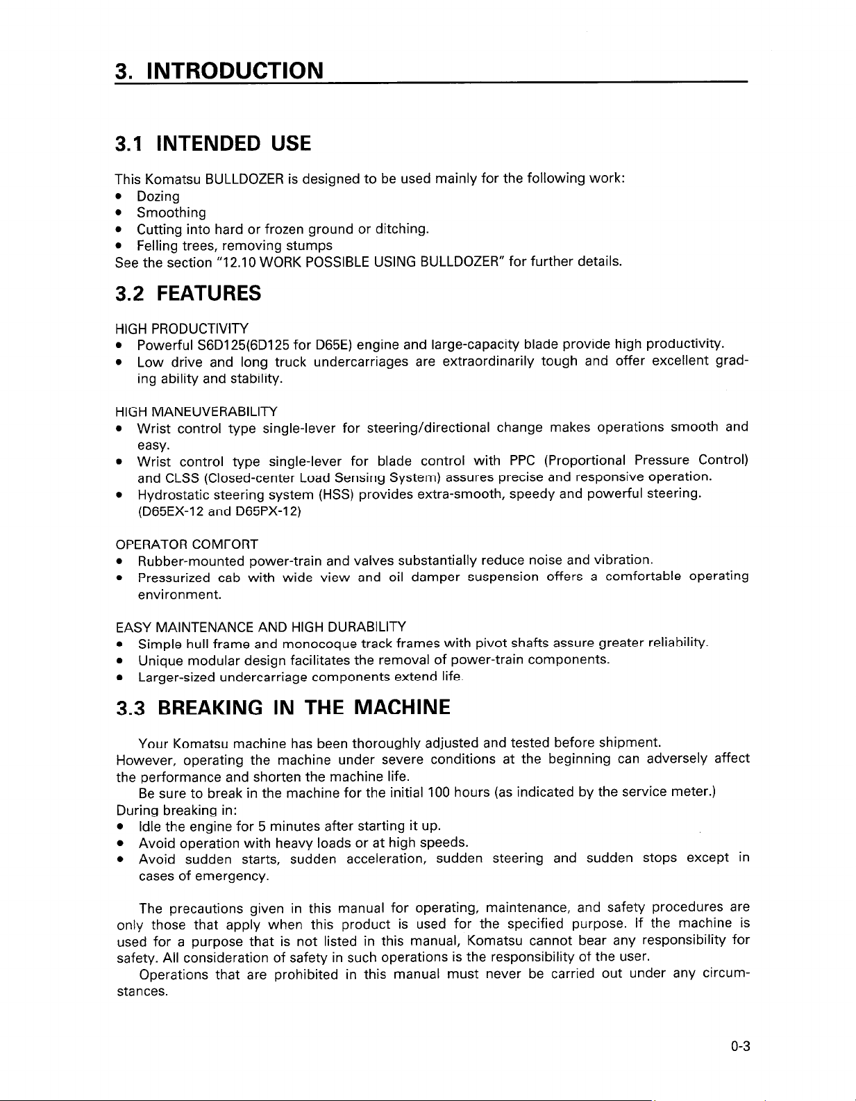
This Komatsu BULLDOZER is designed to be used mainly for the following work:
l Dozing
l Smoothing
l Cutting into hard or frozen ground or ditching.
l Felling trees, removing stumps
See the section “12.10 WORK POSSIBLE USING BULLDOZER” for further details.
3.2 FEATURES
HIGH PRODUCTIVITY
l Powerful S6D125(6D125 for D65E) engine and large-capacity blade provide high productivity.
l Low drive and long truck undercarriages are extraordinarily tough and offer excellent grad-
ing ability and stability.
HIGH MANEUVERABILITY
l Wrist control type single-lever for steering/directional change makes operations smooth and
easy.
l Wrist control type single-lever for blade control with PPC (Proportional Pressure Control)
and CLSS (Closed-center Load Sensing System) assures precise and responsive operation.
l Hydrostatic steering system (HSS) provides extra-smooth, speedy and powerful steering.
(D65EX-12 and D65PX-12)
OPERATOR COMFORT
l Rubber-mounted power-train and valves substantially reduce noise and vibration.
l Pressurized cab with wide view and oil damper suspension offers a comfortable operating
environment.
EASY MAINTENANCE AND HIGH DURABILITY
l Simple hull frame and monocoque track frames with pivot shafts assure greater reliability.
l Unique modular design facilitates the removal of power-train components.
l Larger-sized undercarriage components extend life.
3.3 BREAKING IN THE MACHINE
Your Komatsu machine has been thoroughly adjusted and tested before shipment.
However, operating the machine under severe conditions at the beginning can adversely affect
the performance and shorten the machine life.
Be sure to break in the machine for the initial 100 hours (as indicated by the service meter.)
During breaking in:
l Idle the engine for 5 minutes after starting it up.
l Avoid operation with heavy loads or at high speeds.
l Avoid sudden starts, sudden acceleration, sudden steering and sudden stops except in
cases of emergency.
The precautions given in this manual for operating, maintenance, and safety procedures are
only those that apply when this product is used for the specified purpose. If the machine is
used for a purpose that is not listed in this manual, Komatsu cannot bear any responsibility for
safety. All consideration of safety in such operations is the responsibility of the user.
Operations that are prohibited in this manual must never be carried out under any circum-
stances.
o-3
Page 5
4. LOCATION OF PLATES, TABLE TO ENTER SERIAL NO. AND DISTRIBUTOR
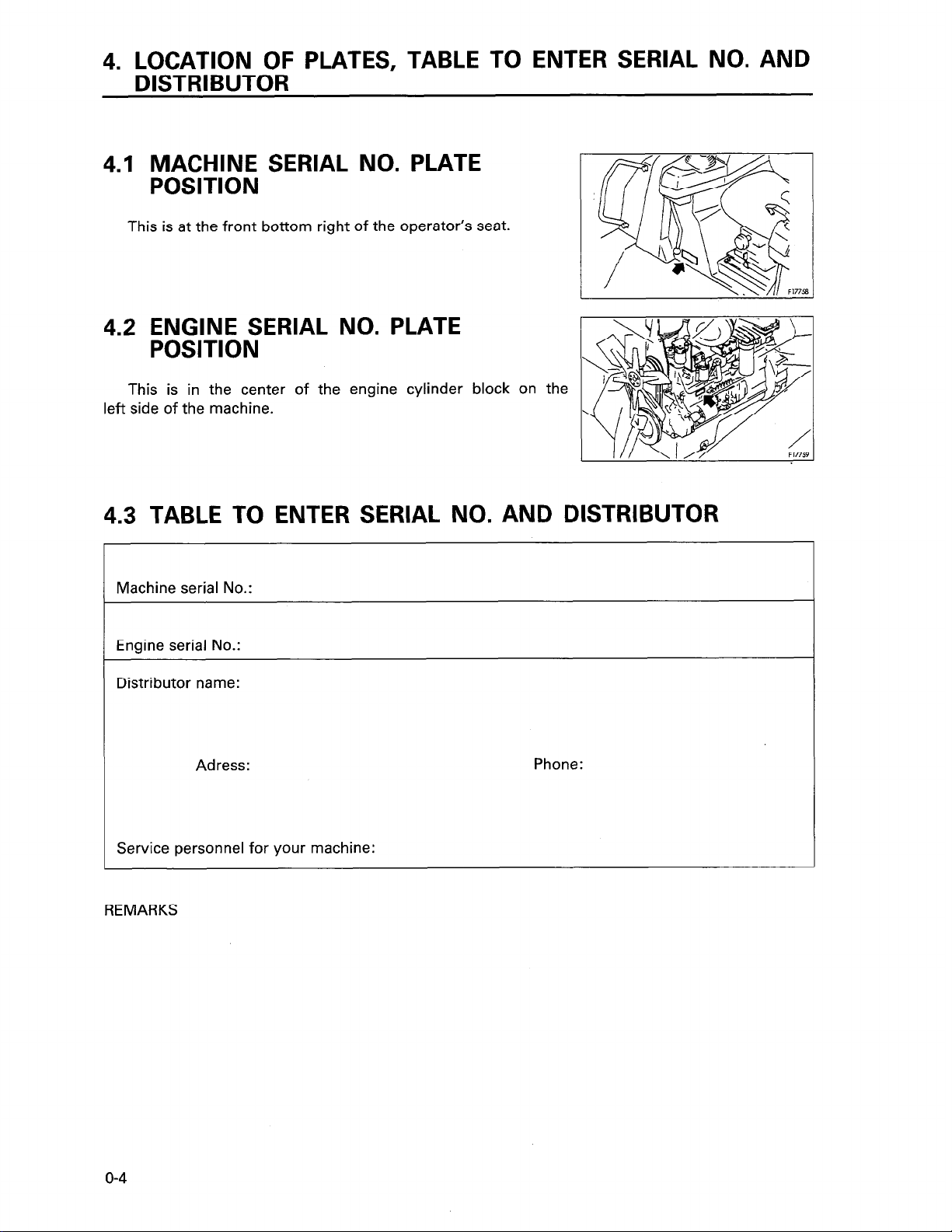
4.1 MACHINE SERIAL NO. PLATE
POSITION
This is at the front bottom right of the operator’s seat.
4.2 ENGINE SERIAL NO. PLATE
POSITION
This is in the center of the engine cylinder
left
side of the machine.
block on the
4.3 TABLE TO ENTER SERIAL NO. AND DISTRIBUTOR
Machine serial No.:
Engine serial No.:
Distributor name:
Adress:
Phone:
Service personnel for your machine:
REMARKS
o-4
Page 6
5. CONTENTS
1. Foreword . . . . . . . . .
2. Safety information
3. Introduction
4. Location of plates, table to enter serial No. and distributor
. . . . . . . . . . . . . . . . . . . . . . . . . . . . . .._..................................................
. . .._..........................................
. . . . . . . . . . . . . . . . . . . . . . . . . .
. . . . . . . . . . . . . . . . . . . . . . . . . . . . . . . . . . . . . . . . . . . . . . . . . . . . . . . . . . . . . . . . . . . . . . . . . . . . . . . . . . . . . . . .
. . . . . . .
. . . . . . . . . . . . . . . . . . . . . . . . . . . . . . . . . . o-4
SAFETY
6. General precautions . . . . . . . . . . . . . . . . . . . . . . . . . . . . . . . . . . . . . . . . . . . . . . . . . _ . . . . . . . . . . . . . . . . . . . . . . . . . .
7. Precautions during operation
7.1. Before starting engine
7.2.
7.3.
7.4. Battery
7.5.
8. Precautions for maintenance
8.1
8.2 During maintenance
9. Position for attaching safety labels
Operating machine ..........
Transportation ...............
.......................
Towing
Before carrying out maintenance
.......................
.....
......
...................................................................
.......................................................................
...................
...................
...................
...................
...................
...................
........................................................
. . . . . . . . . . . . . . . . . . . . . . . . . . .
. . . . . . . .
........
........
........
........
.......................
....................... ......... l-9
....................... ........ I-II
.......................
.......................
.......................
. . . . . . . . . . . . . . . . . . . . . . . . . . . . . . . . .
......... l-9
........ 1-14
........ 1-15
........
O-l
o-2
o-3
1-2
1-16
1-17
1-17
1-19
1-24
OPERATION
10. General view
10.1.
10.2. General view of controls and gauges
Explanation of components
11.
11. 1. Front panel (meters, lamps, switches)
11. 2. Switches
11. 3. Control levers and pedals
11. 4. Fuse box
11. 5. Grease pump holder
11. 6. Shovel holder
11. 7. Door-open lock (machines equipped with cab)
11. 8. Sash glass intermediate lock (machines equipped with cab)
11. 9. Cap with lock
11 .lO. Hot and cool box (machines equipped with cab)
11 .I 1. Door pocket (machines equipped with cab)
11.12. Ashtray (machines equipped with cab)
11.13. Tool box
11.14. Using car radio (machines equipped with cab)
11 .I 5. Using car stereo (machines equipped with cab)
11.16. Handling air conditioner (machines equipped with cab)
11.17. Handling heater (machines equipped with cab)
General view of machine
.......................................................................................
..................................................................
.....................................................
......................................................................
....................................................
................................................................................... 2-20
.................................................................
...................................................................................
......................................................................
..............................................................................
.........................................
..............................................................................
.............................................
..................................................
....................................................................................
.........................................
.........................................
.......................... 2-31
.......................................
........................................
...............................
2-2
2-2
2-3
2-6
2-7
2-22
2-29
2730
2-30
2-30
2-31
2-32
2-32
2-32
2-32
2-33
2-37
2-43
2-47
o-5
Page 7
12. Operation
................................
12. 1. Check before starting engine
12. 2. Starting engine
............................................................................
: .........................................................
.............................................................
12. 3. Operations and checks after starting engine
12. 4. Moving machine
12. 5. Shifting gear
12. 6. Shifting between forward and reverse
12. 7. Steering machine
12. 8. Stopping machine
12. 9. Precautions for operation
12.10. Work possible using bulldozer
12.11. Adjusting posture of work equipment
12.12. Parking machine
12.13. Check after finishing work
12.14. Stopping engine
12.15. Check after stopping engine
12.16. Locking
.....................................................................................
12.17. Tips for longer undercarriage life
...........................................................................
...............................................................................
..................................................
..........................................................................
.........................................................................
.................................................................
...........................................................
...................................................
...........................................................................
................................................................
...........................................................................
..............................................................
........................................................
13. Transportation . . . . . . . . . . . . . . . . . . . . . . . . . . . . . . . . . . . . . . . . . .
13.1. Loading, unloading work
13.2. Precautions for loading
. . . . . . . . . . . . . . . . . . . . . . .
. . . . . . . . . . . . . . . . . . . . . . . . .
13.3. Precautions for transportation . . . . . . . . . . . . . . . . .
13.4. Precautions when removing work equipment
13.5. Removing cab (machines equipped with cab)
............................................
......
......
......
. . . . .
. . . . .
......
......
. . . . . .
......
......
......
......
. . . .
. .
. . . . .
. . . . .
. . . . . 2-88
. . .
. .
. . . . .
2-48
2-48
2-58
2-64
2-66
2-67
2-68
2-69
2-73
2-74
2-76
2-77
2-80
2-81
2-82
2-83
2-83
2-84
2-87
2-87
2-88
2-89
2-89
14. Cold weather operation
14.1. Precautions for low temperature
14.2. After completion of work
14.3. After cold weather
.................................
................
........................
...............................
15. Long-term storage (more than one month)
15.1. Before storage
15.2. During storage
15.3. After storage
16. Troubleshooting
16.1. After running out of fuel
16.2. If battery is discharged
16.3. Other trouble
...................................
...................................
.....................................
.........................................
.........................
...........................
.....................................
.......................................
............................
.......................................
.......................................
......... ........................................
........................................
........................................
..............................
........................................
........................................
........................................
........................................
2-90
........... 2-90
2-92
2-92
2-93
2-93
2-93
.......... 2-94
2-95
2-95
2-95
2-98
O-6
Page 8
MAINTENANCE
Guides to maintenance
17.
5. CONTENTS
................................................................................................................................
3-2
Outlines of service
18.
18.1.
18.2.
Wear parts list
19.
Use of fuel, coolant and lubricants according to ambient temperature
20.
Standard tightening torques for bolts and nuts
21.
21 .I.
21 .2.
Periodic
22.
Maintenance schedule chart
23.
Service
24.
24.1.
24.2. Check before starting
24.3.
24.4.
24.5.
24.6.
24.7.
24.8.
Outline of oil, fuel, coolant
Relating to electric system
Introduction of necessary tools
Torque list
replacement
procedure
When required
Every 50 hours service
Every 250 hours service
Every 500 hours
Every 1000 hours service
Every 2000 hours service
Every 4000 hours service
..........................................................................................................................................
..............................................................................................................
..............................................................................................................
..................................................................................................................................................
...............................................................................
....................................................................................................
...........................................................................................................................................
of safety critical
....................................................................................................................
.........................................................................................................................................
..................................................................................................................................
......................................................................................................................
...................................................................................................................
.................................................................................................................
service
.................................................................................................................
...............................................................................................................
...............................................................................................................
...............................................................................................................
parts .....................................................................................
.................................
3-5
3-5
3-8
3-9
3-10
3-l 4
3-14
3-l 5
3-l 6
3-20
3-23
3-23
3-42
3-47
3-48
3-60
3-64
3-69
3-72
SPECIFICATIONS
25. Specifications
. . . . . . . . . . . . . . . . . . . . . . . . . . . . . . . . . . . . . . . . . . . . . . . . . . . . . . . . . . . . . . . . . . . . . . . . . . . . . . . . . . . . . . . . . . . . . . . . . . . . . . . . . . . . . . . . . . . . . . . . ..........................
OPTIONS, ATTACHMENTS
General
26.
26.1.
Using seat belt
27.
27.1.
27.2.
Handling
28.
29.
Handling accumulator
29.1.
precautions
Precautions related
Fasten the belt and
Adjust the belt length in the following manner
deluxe
Method of releasing pressure in operating circuit on machine equipped
with accumulator
......................................................................................................................................
to safety ..........................................................................................................
.................................................................................................................................................
remove it in the
.....................................................................................................................................
seat
..................................................................................................................................
................................................................................................................................
following manner
........................................................................
.........................................................
4-2
5-2
5-2
5-3
5-3
5-3
5-5
5-7
5-7
o-7
Page 9

SAFETY
WARNING
A
Read and follow all safety precautions. Failure to do so may result in serious injury or
death.
This safety section also contains precautions for optional equipment and attachments.
l-l
Page 10
6. GENERAL PRECAUTIONS
SAFETY RULES
l ONLY trained and authorized personnel can operate and maintain the machine.
l Follow all safety rules, precautions and instructions when operating or performing main-
tenance on the machine.
l When working with another operator or a person on worksite traffic duty, be sure all
personnel understand all hand signals that are to be used.
SAFETY FEATURES
Be sure all guards and covers are in their proper position. Have guards and covers repaired if damaged.
Proper position -+ See “12.1 .I WALK-AROUND CHECK”.
Use safety features such as safety lock and seat belts properly.
NEVER remove any safety features. ALWAYS keep them in good operating condition.
Safety lever -+ See “12.12 PARKING MACHINE”.
Seat belts -, See “27. USING SEAT BELT”.
these safety precautions.
AWARNING: For reasons of safety, always follow
Improper use of safety features could result in serious bodily injury or death.
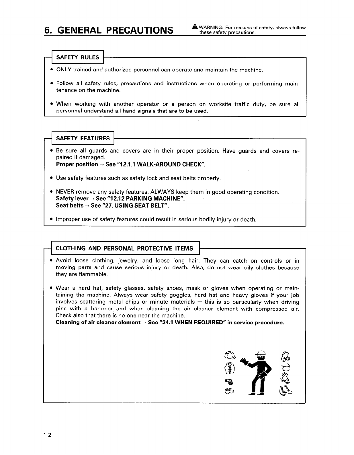
CLOTHING AND PERSONAL PROTECTIVE ITEMS
l Avoid loose clothing, jewelry, and loose long hair. They can catch on controls or in
moving parts and cause serious injury or death. Also, do not wear oily clothes because
they are flammable.
l Wear a hard hat, safety glasses, safety shoes, mask or gloves when operating or main-
taining the machine. Always wear safety goggles, hard hat and heavy gloves if your job
involves scattering metal chips or minute materials - this is so particularly when driving
pins with a hammer, and when cleaning the air cleaner element with compressed air.
Check also that there is no one near the machine.
Cleaning of air cleaner element
-, See “24.1 WHEN REQUIRED” in service procedure.
l-2
Page 11
AWARNING: Failure to follow these safety precautions may lead to a
serious accident.
UNAUTHORIZED MODIFICATION
l Any modification made without authorization from Komatsu can create hazards.
l Before making a modification, consult your Komatsu distributor. Komatsu will not be re-
sponsible for any injury or damage caused by any unauthorized modification.
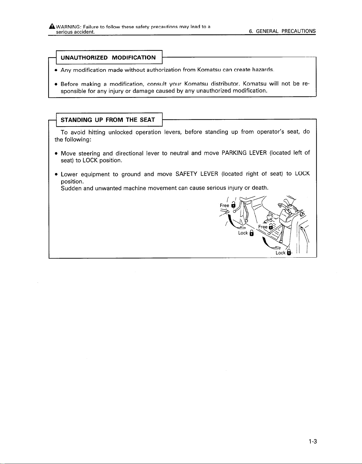
STANDING UP FROM THE SEAT
To avoid hitting unlocked operation levers, before standing up from operator’s seat, do
the following:
Move steering and directional lever to neutral and move PARKING LEVER (located left of
seat) to LOCK position.
Lower equipment to ground and move SAFETY LEVER (located right of seat) to LOCK
position.
Sudden and unwanted machine movement can cause serious injury or death.
6. GENERAL PRECAUTIONS
l-3
Page 12
6. GENERAL PRECAUTIONS A WARNING: For reasons of safety, always follow these safety precautions.
NEVER jump on or off the machine. NEVER get on or off a moving machine.
When mounting and dismounting, face the machine and use the handholds steps. Maintain three-point contact to be sure that you do not fall from the machine.
Do not hold any control levers when getting on of off the machine.
Repair any damaged handhold or step, and tighten any loose bolts. Handholds and
steps must be free of oil, grease and excessive dirt.
When mounting or dismounting, or when moving along the top of the track, if you hold
the door handle and the door is not properly closed, the door may move and cause you
to fall. Always make sure that the door is properly closed.
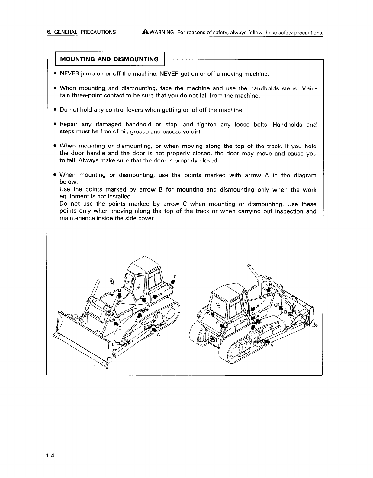
When mounting or dismounting, use the points marked with arrow A in the diagram
below.
Use the points marked by arrow B for mounting and dismounting only when the work
equipment is not installed.
Do not use the points marked by arrow C when mounting or dismounting. Use these
points only when moving along the top of the track or when carrying out inspection and
maintenance inside the side cover.
l-4
Page 13
AWARNING: Failure to
serious accident.
follow these safety precautions may lead to a
6. GENERAL PRECAUTIONS
RE PREVENTION FOR FUEL
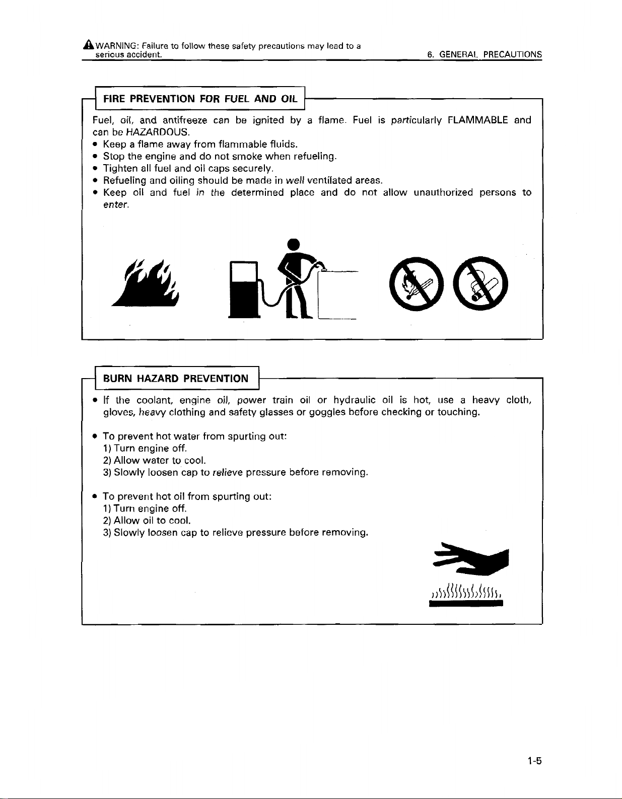
Fuel,
oil,
and antifreeze can be ignited by a flame. Fuel is
AND OIL
particularly FLAMMABLE and
can be HAZARDOUS.
Keep a flame away from flammable fluids.
Stop the engine and do not smoke when refueling.
Tighten all fuel and oil caps securely.
Refueling and oiling should be made in well ventilated areas.
Keep oil and fuel in the determined place and do not allow unauthorized persons to
enter.
- BURN HAZARD PREVENTION
l
If the coolant, engine oil, power train oil or hydraulic oil is hot, use a heavy cloth,
gloves, heavy clothing and safety glasses or goggles before checking or touching.
l
To prevent hot water from spurting out:
1) Turn engine off.
2) Allow water to cool.
3) Slowly loosen cap to relieve pressure before removing.
l
To prevent hot oil from spurting out:
1) Turn engine off.
2) Allow oil to cool.
3) Slowly loosen cap to relieve pressure before removing.
l-5
Page 14
6. GENERAL PRECAUTIONS AWARNING: For reasons of safety, always follow these safety precautions.
ASBESTOS DUST HAZARD PREVENTION 1
l-i
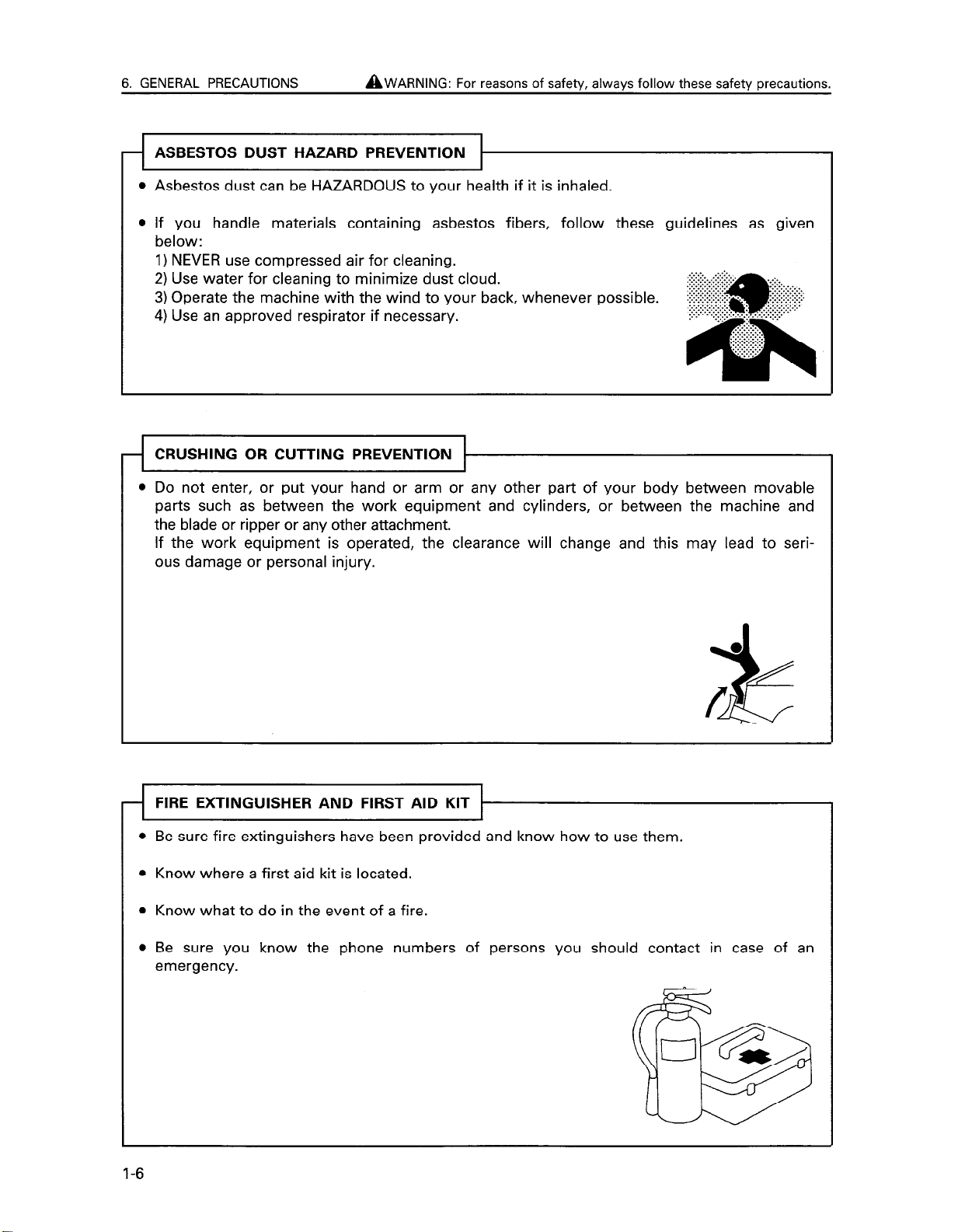
Asbestos dust can be HAZARDOUS to your health if it is inhaled.
If you handle materials containing asbestos fibers, follow these guidelines as given
below:
1) NEVER use compressed air for cleaning.
2) Use water for cleaning to minimize dust cloud.
3) Operate the machine with the wind to your back, whenever possible.
4) Use an approved respirator if necessary.
CRUSHING OR CUTTING PREVENTION
l Do not enter, or put your hand or arm or any other part of your body between movable
parts such as between the work equipment and cylinders, or between the machine and
the blade or ripper or any other attachment.
If the work equipment is operated, the clearance will change and this may lead to seri-
ous damage or personal injury.
FIRE EXTINGUISHER AND FIRST AID KIT
l Be sure fire extinguishers have been provided and know how to use them.
l Know where a first aid kit is located.
l Know what to do in the event of a fire.
l Be sure you know the phone numbers of persons you should contact in case of an
emergency.
1-6
Page 15

AWARNING: Failure to follow these safety precautions may lead to a
serious accident.
PRECAUTIONS FOR ROPS 1
r-i
I ’
Do not operate machine with ROPS removed if equipped.
The ROPS is installed to protect the operator if the machine should overturn. It is designed not only to take the load when the machine overturns, but also to absorb the
impact energy.
The Komatsu ROPS fulfills all worldwide regulations and standards, but if any unauthorized modification is carried out on it, or if it is damaged when the machine overturns,
its strength will be reduced and it will not be able to provide its original capacity. It will
be able to provide this capacity only if modifications and repairs are carried out in the
specified way.
When carrying out modification or repairs, always consult your Komatsu distributor first.
Even when the ROPS is installed, if you do not fasten your seat belt securely, it cannot
protect you properly. Always fasten your seat belt when operating the machine.
Seat belts -f See “27. USING SEAT BELT.”
,
6. GENERAL PRECAUTIONS
1
PRECAUTIONS FOR ATTACHMENTS
-r--
l When installing and using an optional attachment, read the instruction manual for the at-
tachment and the information related to attachments in this manual.
l Do not use attachments that are not authorized by Komatsu or your Komatsu distributor.
Use of unauthorized attachments could create a safety problem and adversely affect the
proper operation and useful life of the machine.
l Any injuries, accidents, product failures resulting from the use of unauthorized attach-
ments will not be the responsibility of Komatsu.
1-7
Page 16
6. GENERAL PRECAUTIONS
MACHINES WITH ACCUMULATOR
AWARNING: For reasons of safety, always follow these safety precautions.
On machines equipped with an accumulator,
for a short time after the engine is
stopped, if the work equipment control lever is moved to the LOWER position, the work
equipment will move down under its own weight.
After stopping the engine, always place the safety lock lever in the LOCK position.
When releasing the pressure inside the work equipment circuit on machines equipped
with an accumulator, follow the procedure given in the inspection and maintenance section.
Method of releasing pressure + See “29. HANDLING ACCUMULATOR”.
The accumulator is filled with high-pressure nitrogen gas, and it is extremely dangerous
if it is handled in the wrong way. Always observe the following precautions.
l Never make any hole in the accumulator or expose it to flame or fire.
l Do not weld any boss to the accumulator.
l When carrying out disassembly or maintenance of the accumulator, or when disposing
of the accumulator, it is necessary to release the gas from the accumulator. A special
air bleed valve is necessary for this operation,
so please contact your Komatsu
distributor.
Gas in accumulator -+ See “29. HANDLING ACCUMULATOR”.
1-8
Page 17
7. PRECAUTIONS DURING
OPERATION
AWARNING: Failure to follow these safety precautions may
lead to a serious accident.
7.1 BEFORE STARTING ENGINE
SAFETY AT WORKSITE
4
Before starting the engine, thoroughly check the area
for any unusual conditions that could be dangerous.
Before starting the engine, examine the terrain and soil
conditions of the worksite. Determine the best and safest method of operation.
If you need to operate on a street, protect pedestrians
and cars by designating a person for worksite traffic
duty or by installing fences around the worksite.
If water lines, gas lines, and high-voltage electrical lines
may be buried under the worksite, contact each utility
and identify their locations. Be careful not to sever or
cut any of these lines.
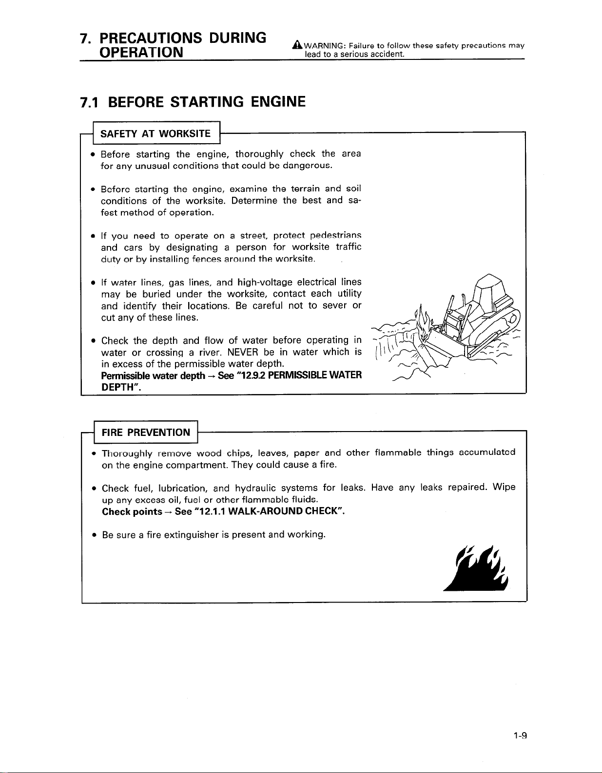
Check the depth and flow of water before operating in
water or crossing a river. NEVER be in water which is
in excess of the permissible water depth.
Permissible water depth -, See “12.9.2 PERMISSIBLE WATER
DEPTH”.
FIRE PREVENTION
Thoroughly remove wood chips, leaves, paper and other flammable things accumulated
on the engine compartment. They could cause a fire.
Check fuel, lubrication, and hydraulic systems for leaks. Have any leaks repaired. Wipe
up any excess oil, fuel or other flammable fluids.
Check points + See “12.1 .I WALK-AROUND CHECK”.
Be sure a fire extinguisher is present and working.
l-9
Page 18

7. PRECAUTIONS DURING OPERATION
..:.::i::.:..
..:..::..:.
:.>:.:.>:.:
IN OPERATOR’S CAB
Do not leave tools or spare parts lying around in the operator’s compartment. They may
damage or break the control levers or switches. Always put them in the tool box on the
left side of the machine.
Keep the cab floor, controls, steps and handholds free of oil, grease, snow, and excess
dirt.
Check the seat belt, buckle and hardware for damage or wear. Replace any worn or
damaged parts. Always use seat belts when operating your machine.
Seat belts + See “27.USING SEAT BELT”.
l If it is necessary to start the engine within an enclosed area, provide adequate ventila-
tion. Exhaust fumes from the engine can KILL.
A WARNING: For reasons of safety, always follow these safety precautions.
..:.>:.. ..>:::_.
.-...........-........ ..c.
::........::..:
.‘.....‘.‘.5’...’ ..::::::.
pa: J$$$ii:
:::::.:::::::: . . . . . . :. .._. :.:.:::y
. . . . . .
. . . . . . . . . . . . . . .
. . . . . . . . . . .
. .
A
:::.
PRECAUTIONS FOR MIRRORS, WINDOWS AND LIGHTS
l Remove all dirt from the surface of the windows and lights to ensure that you can see
well.
l Adjust the rear view mirror so that you can see clearly from the operator’s seat, and always
keep the surface of the mirror clean. If any glass is broken, replace it with a new part.
l Check that the head lamps and rear lamps are installed to match the operating con-
ditions. Check also that they light up properly.
I-IO
Page 19
AWARNING: Failure to follow these safety precautions may lead to a
serious accident.
7. PRECAUTIONS DURING OPERATION
7.2 OPERATING MACHINE
WHEN STARTING ENGINE
Walk around your machine again just before mounting it, checking for people and objects that might be in the way.
NEVER start the engine if a warning tag has been attached to the control.
When starting the engine, sound the horn as an alert.
Start and operate the machine only while seated.
Do not allow anyone other than the operator to ride in the cab or on the machine body.
For machines equipped with a reverse warning
device operates correctly.
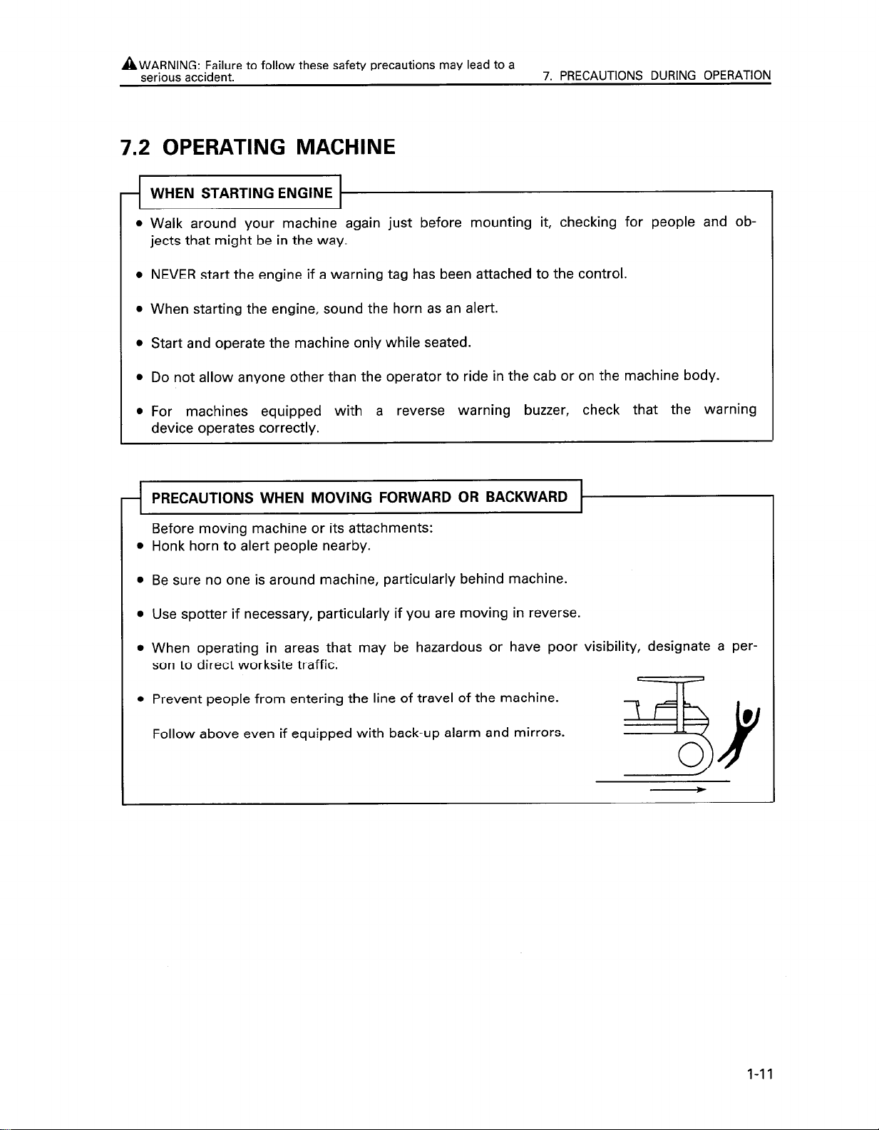
PRECAUTIONS WHEN MOVING FORWARD OR BACKWARD
Before moving machine or its attachments:
Honk horn to alert people nearby.
Be sure no one is around machine, particularly behind machine.
Use spotter if necessary, particularly if you are moving in reverse.
When operating in areas that may be hazardous or have poor visibility, designate a per-
son to direct worksite traffic.
Prevent people from entering the line of travel of the machine.
Follow above even if equipped with back-up alarm and mirrors.
buzzer, check that the warning
1-11
Page 20
7. PRECAUTIONS DURING OPERATION
AWARNING: For reasons of safety, always follow these safety precautions.
TRAVELING ON SLOPES
Traveling on hills, banks or slopes that are steep could result in the machine tipping
over or slipping.
On hills, banks or slopes, carry the work equipment closer to the ground, approximately
20 to 30 cm above the ground. In case of emergency, quickly lower the
work equipment
to the ground to help the machine stop and prevent it from tipping over.
Do not change direction on slopes. Avoid sideways travel whenever
possible: rather
travel up and down the slopes.
Do not travel up and down on grass, fallen leaves, and wet steel plates.
These materials
may allow the machine to slip, if it is traveling sideways. Keep travel speed very low.
When traveling downhill, drive slowly and use the engine as a brake.
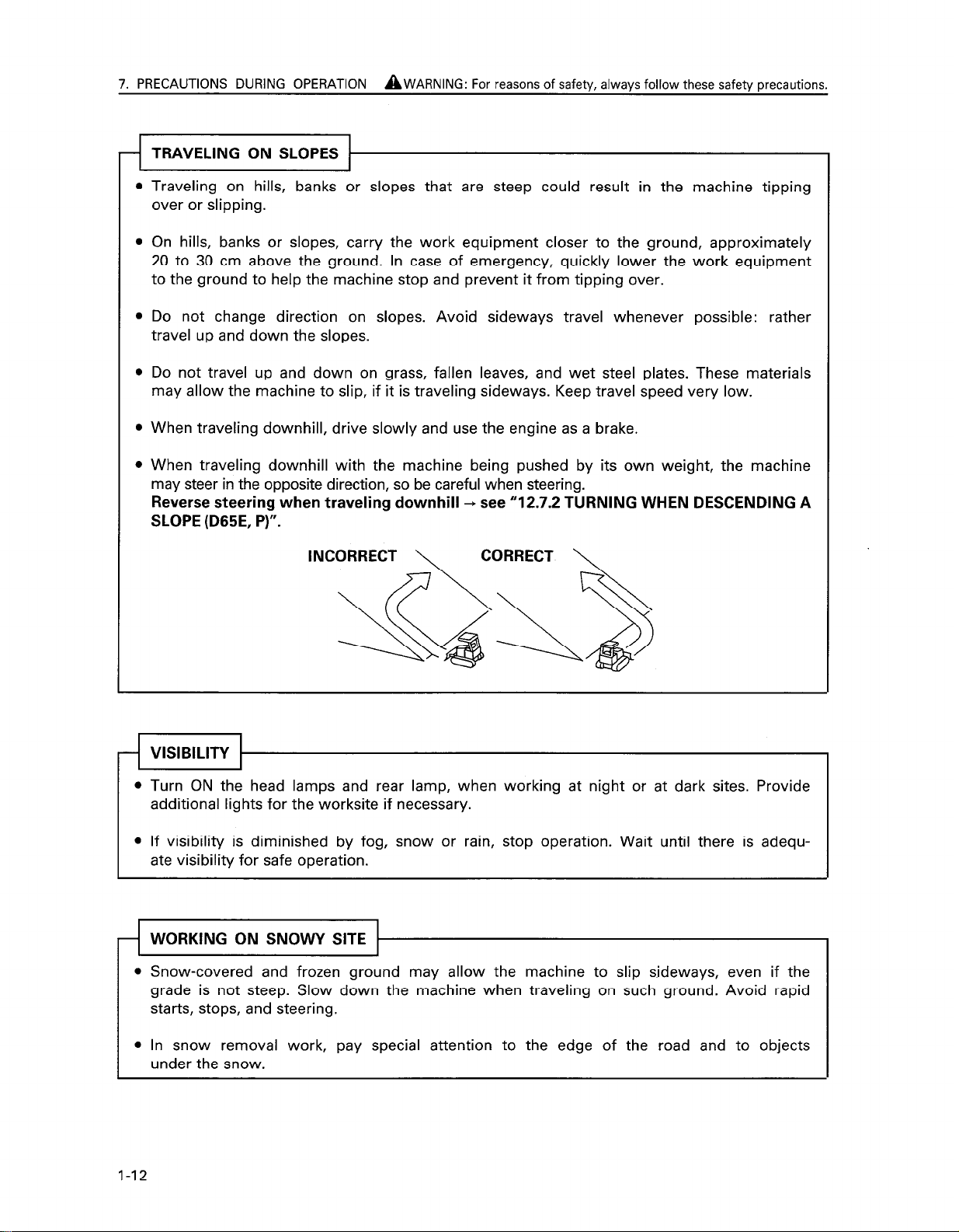
When traveling downhill with the machine being pushed by its own weight, the machine
may steer in the opposite direction, so be careful when steering.
Reverse steering when traveling downhill
+ see “12.7.2 TURNING WHEN DESCENDING A
SLOPE (D65E, P)“.
INCORRECT
VISIBILITY
Turn ON the head lamps and rear lamp, when working at night or at dark sites. Provide
additional lights for the worksite if necessary.
If visibility is diminished by fog, snow or rain, stop operation. Wait until there is adequate visibility for safe operation.
WORKING ON SNOWY SITE 1
l Snow-covered and frozen ground may allow the machine to slip sideways, even if the
grade is not steep. Slow down the machine when traveling on such ground. Avoid rapid
starts, stops, and steering.
l In snow removal work, pay special attention to the edge of the road and to objects
under the snow.
1-12
Page 21
AWARNING: Failure to follow these safety precautions may lead to a
serious accident.
WORKING ON LOOSE GROUND
Avoid operating your machine too close to the edge of cliffs, overhangs, and deep ditches. If these areas collapse, your machine could fall or tip over and result in serious in-
jury or death. Remember that the soil after heavy rain or blasting is weakened in these
areas.
Earth laid on the ground and the soil near ditches are loose. They can collapse under
the weight or vibration of your machine.
Install the HEAD GUARD or FOPS if working in areas where there is danger of falling
rocks and dirt.
When working in places where there is danger of falling rocks or danger of the machine
turning over, install ROPS and a seat belt.
PARKING THE MACHINE 1
-I
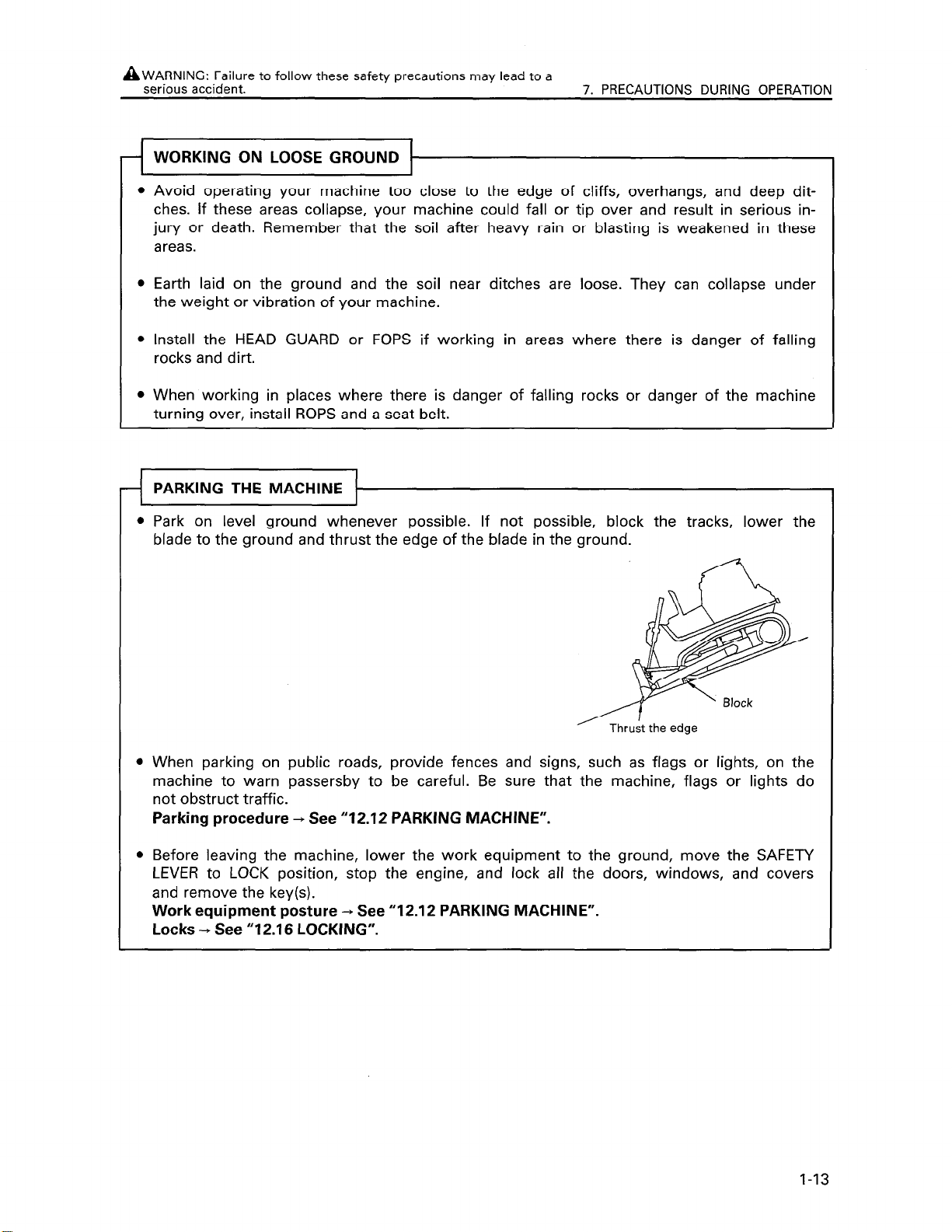
Park on level ground whenever possible. If not possible, block the tracks, lower the
blade to the ground and thrust the edge of the blade in the ground.
7. PRECAUTIONS DURING OPERATION
When parking on public roads, provide fences and signs, such as flags or lights, on the
machine to warn passersby to be careful. Be sure that the machine, flags or lights do
not obstruct traffic.
Parking procedure + See “12.12 PARKING MACHINE”.
Before leaving the machine, lower the work equipment to the ground, move the SAFETY
LEVER to LOCK position, stop the engine, and lock all the doors, windows, and covers
and remove the key(s).
Work equipment posture -, See “12.12 PARKING MACHINE”.
Locks + See “12.16 LOCKING”.
1-13
Page 22
7. PRECAUTIONS DURING OPERATION
AWARNING: For reasons of safety, always follow these safety precautions.
7.3 TRANSPORTATION
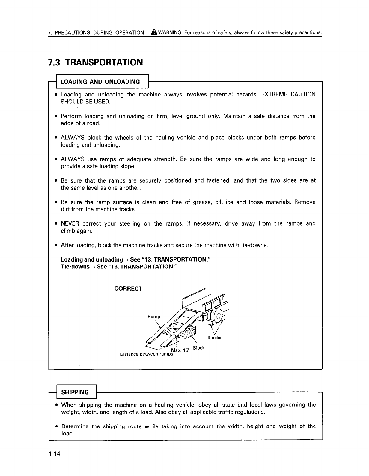
LOADING AND UNLOADING
-I
Loading and unloading the machine always involves potential hazards. EXTREME CAUTION
SHOULD BE USED.
Perform loading and unloading on firm, level ground only. Maintain a safe distance from the
edge of a road.
ALWAYS block the wheels of the hauling vehicle and place blocks under both ramps before
loading and unloading.
ALWAYS use ramps of adequate strength. Be sure the ramps are wide and long enough to
provide a safe loading slope.
Be sure that the ramps are securely positioned and fastened, and that the two sides are at
the same level as one another.
Be sure the ramp surface is clean and free of grease, oil, ice and loose materials. Remove
dirt from the machine tracks.
NEVER correct your steering on the ramps. If necessary, drive away from the ramps and
climb again.
After loading, block the machine tracks and secure the machine with tie-downs.
Loading and unloading -f See “13. TRANSPORTATION.”
Tie-downs + See “13. TRANSPORTATION.”
CORRECT
Distance between ramps
SHIPPING
l When shipping the machine on a hauling vehicle, obey all state and local laws governing the
weight, width, and length of a load. Also obey all applicable traffic regulations.
l Determine the shipping route while taking into account the width, height and weight of the
load.
1-14
Page 23
AWARNING: Failure to follow these safety precautions may lead to a
serious accident.
7.4 BATTERY
7. PRECAUTIONS DURING OPERATION
BATTERY HAZARD PREVENTION
0
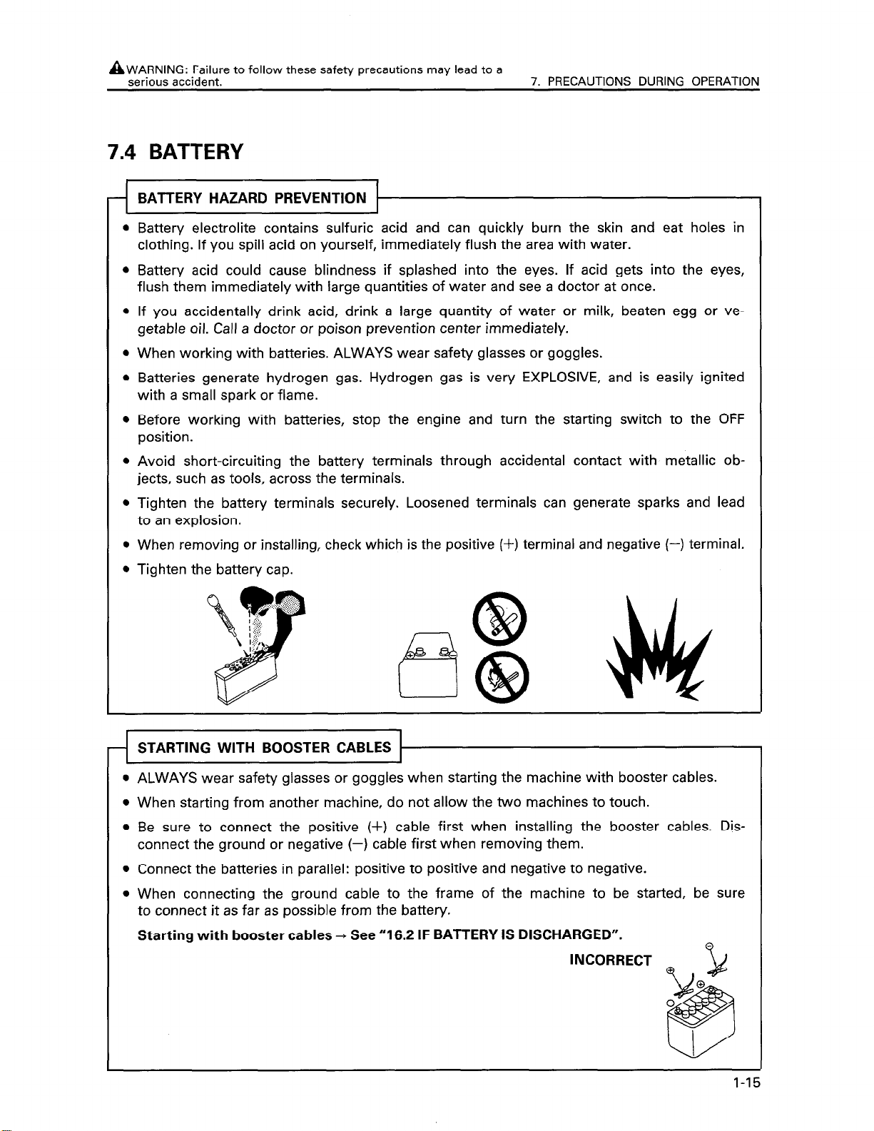
Battery electrolite contains sulfuric acid and can quickly burn the skin and eat holes in
clothing. If you spill acid on yourself, immediately flush the area with water.
l
Battery acid could cause blindness if splashed into the eyes. If acid gets into the eyes,
flush them immediately with large quantities of water and see a doctor at once.
l
If you accidentally drink acid, drink a large quantity of water or milk, beaten egg or ve-
getable oil. Call a doctor or poison prevention center immediately.
l
When working with batteries. ALWAYS wear safety glasses or goggles.
0
Batteries generate hydrogen gas. Hydrogen gas is very EXPLOSIVE, and is easily ignited
with a small spark or flame.
l
Before working with batteries, stop the engine and turn the starting switch to the OFF
position.
l
Avoid short-circuiting the battery terminals through accidental contact with metallic objects, such as tools, across the terminals.
l
Tighten the battery terminals securely. Loosened terminals can generate sparks and lead
to an explosion.
l
When removing or installing, check which is the positive (+) terminal and negative (-) terminal.
l
Tighten the battery cap.
1
STARTING WITH BOOSTER CABLES 11
-I
ALWAYS wear safety glasses or goggles when starting the machine with booster cables.
When starting from another machine, do not allow the two machines to touch.
Be sure to connect the positive (+) cable first when installing the booster cables. Dis-
connect the ground or negative (-) cable first when removing them.
Connect the batteries in parallel: positive to positive and negative to negative.
When connecting the ground cable to the frame of the machine to be started, be sure
to connect it as far as possible from the battery.
Starting with booster cables -, See “16.2 IF BATTERY IS DISCHARGED”.
INCORRECT
1-15
Page 24

7. PRECAUTIONS DURING OPERATION
AWARNING: For reasons of safety, always follow these safety precautions.
7.5 TOWING
WHEN TOWING THE MACHINE, FIX THE WIRE
TO THE REAR HITCH PIN OR RIPPER.
Injury or death could result if a disabled machine is towed incorrectly.
If your machine is towed by another machine, ALWAYS use a wire rope with a sufficient
towing capacity.
When the machine is towed, always set the steering and directional lever to the N (neutral)
position.
NEVER allow a disabled machine to be towed on a slope.
Do not use a kinked or frayed wire rope.
Do not straddle the towing cable or wire rope.
When connecting up a towing machine, do not let anyone enter the area between the
ing machine and the equipment being towed.
Set the towing machine and the towing connection of the equipment being towed
straight line when connecting it.
Take up the slack in the wire rope and tow the machine.
tow-
in a
1-16
Page 25
8. PRECAUTIONS FOR MAINTENANCE
AWARNING: Failure to follow these safety precautions may
lead to a serious accident.
8.1 BEFORE CARRYING OUT MAINTENANCE
WARNING TAG 1
-1
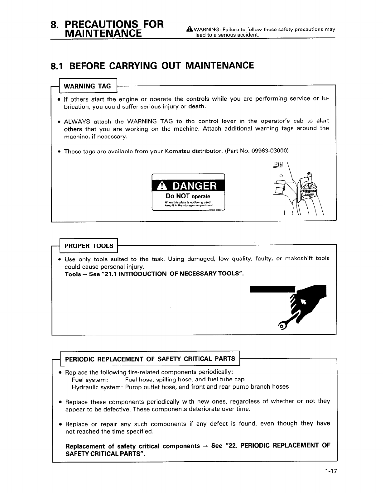
If others start the engine or operate the controls while you are performing service or lu-
brication, you could suffer serious injury or death.
ALWAYS attach the WARNING TAG to the control lever in the operator’s cab to alert
others that you are working on the machine. Attach additional warning tags around the
machine, if necessary.
These tags are available from your Komatsu distributor. (Part No. 09963-03000)
PROPER TOOLS
l Use only tools suited to the task. Using damaged, low quality, faulty, or makeshift tools
could cause personal injury.
Tools + See “21 .I INTRODUCTION OF NECESSARY TOOLS”.
-9
PERIODIC REPLACE
Replace the following fire-related components periodically:
Fuel system:
Hydraulic system: Pump outlet hose, and front and rear pump branch hoses
Replace these components periodically with new ones, regardless of whether or not they
appear to be defective. These components deteriorate over time.
Replace or repair any such components if any defect is found, even though they have
not reached the time specified.
Fuel hose, spilling hose, and fuel tube cap
0
4
Replacement of safety critical components -, See “22. PERIODIC REPLACEMENT OF
SAFETY CRITICAL PARTS”.
1-17
Page 26

AWARNING: For reasons of safety, always follow these safety
8. PRECAUTIONS FOR MAINTENANCE
OUT INSPECTION AND MAINTENANCE
Always stop the machine on firm flat ground and stop the engine before carrying out inspection and maintenance.
If it is necessary to run the engine when carrying out maintenance, such as when cleaning
the inside of the radiator, place the safety lock lever at the LOCK position and carry out the
operation with two workers.
One worker should sit in the operator’s seat so that he can stop the engine immediately if
necessary. He should also be extremely careful not to touch any lever by mistake. Touch the
levers only when they have to be operated.
precautions.
The worker carrying out the maintenance should be extremely careful not to
caught in the moving parts.
If maintenance is carried out with the work equipment raised, always support it
blocks.
OFF
touch or get
securely with
START
1-18
Page 27
AWARNING: Failure to follow these safety precautions may
lead to a serious accident.
8. PRECAUTIONS FOR MAINTENANCE
8.2 DURING MAINTENANCE
l Only authorized personnel can service and repair the machine. Extra precaution should be
used when grinding, welding, and using a sledge-hammer.
ATTACHMENTS
0
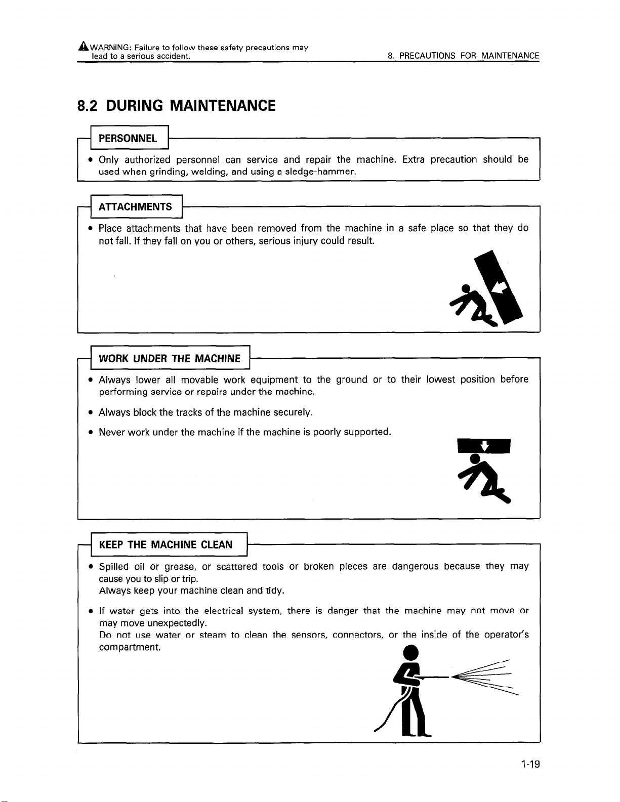
Place attachments that have been removed from the machine in a safe place so that they do
not fall. If they fall on you or others, serious injury could result.
l Always lower all movable work equipment to the ground or to their lowest position before
performing service or repairs under the machine.
l Always block the tracks of the machine securely.
l Never work under the machine if the machine is poorly supported.
KEEP THE MACHINE CLEAN
4
Spilled oil or grease, or scattered tools or broken pieces are dangerous because they may
cause you to slip or trip.
Always keep your machine clean and tidy.
If water gets into the electrical system, there is danger that the machine may not move or
may move unexpectedly.
Do not use water or steam to clean the sensors, connectors, or the inside of the operator’s
compartment.
1-19
Page 28
AWARNING: For reasons of safety, always follow these safety
8. PRECAUTIONS FOR MAINTENANCE
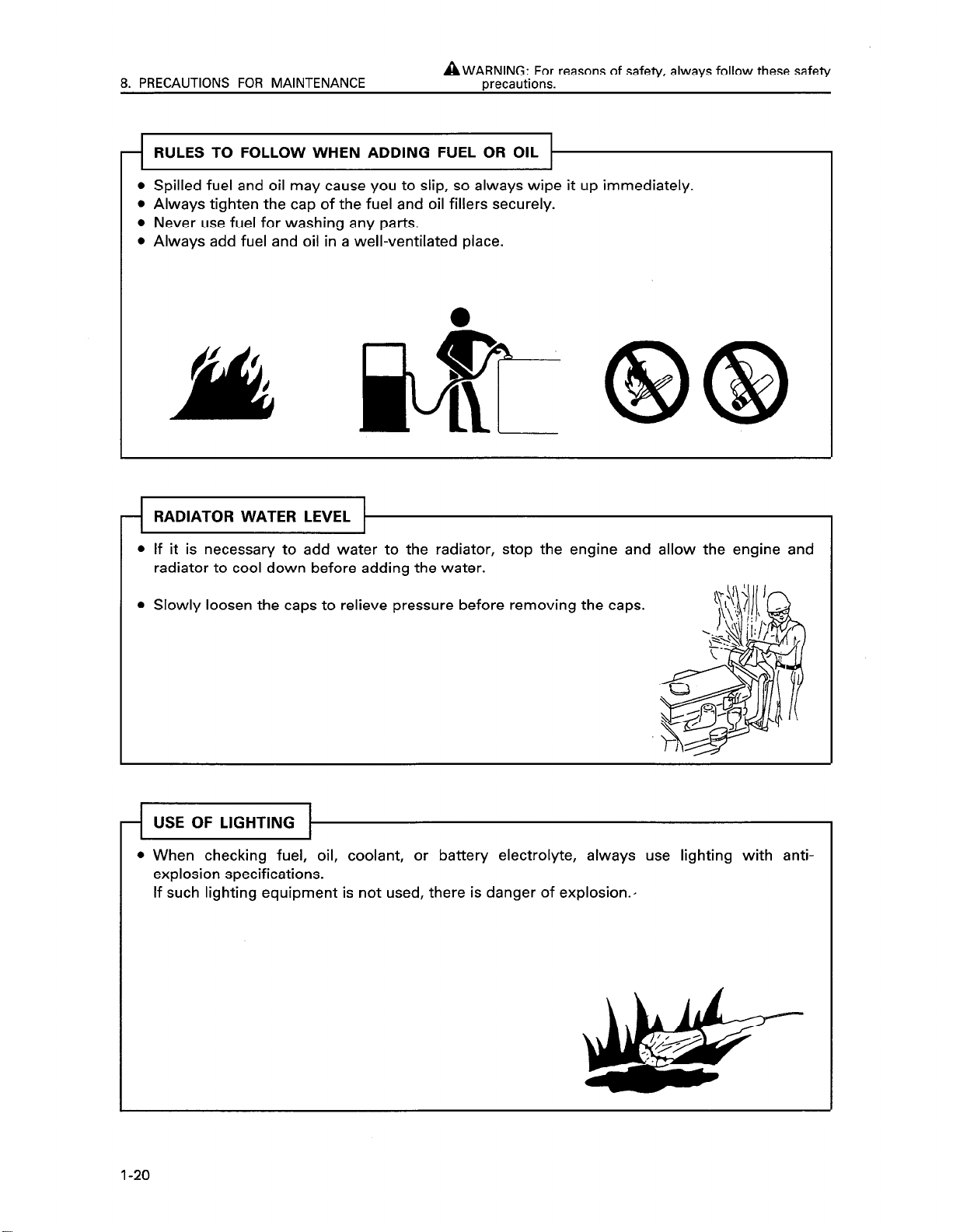
l Spilled fuel and oil may cause you to slip, so always wipe it up immediately.
l Always tighten the cap of the fuel and oil fillers securely.
l Never use fuel for washing any parts.
l Always add fuel and oil in a well-ventilated place.
RADIATOR WATER LEVEL
mecautions.
l If it is necessary to add water to the radiator, stop the engine and allow the engine and
radiator to cool down before adding the water.
l Slowly loosen the caps to relieve pressure before removing the caps.
USE OF LIGHTING
-I
l When checking fuel, oil, coolant, or battery electrolyte, always use lighting with anti-
explosion specifications.
If such lighting equipment is not used, there is danger of explosion.,
I-20
&k&F---
Page 29
AWARNING: Failure to follow these safety precautions may
lead to a serious accident.
PRECAUTIONS WITH BATTERY
-I
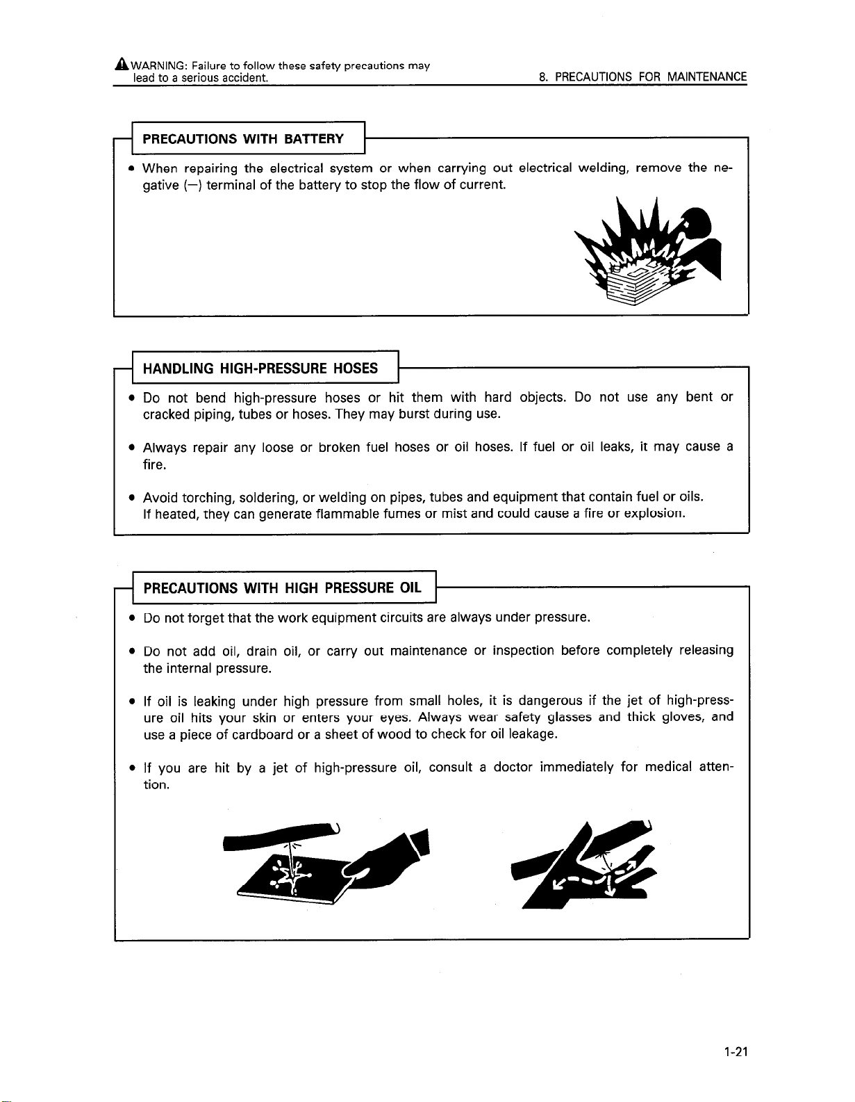
l When repairing the electrical system or when carrying out electrical welding, remove the ne-
gative (-) terminal of the battery to stop the flow of current.
HANDLING HIGH-PRESSURE HOSES
4
l Do not bend high-pressure hoses or hit them with hard objects. Do not use any bent or
cracked piping, tubes or hoses. They may burst during use.
l Always repair any loose or broken fuel hoses or oil hoses. If fuel or oil leaks, it may cause a
fire.
8. PRECAUTIONS FOR MAINTENANCE
l Avoid torching, soldering, or welding on pipes, tubes and equipment that contain fuel or oils.
If heated, they can generate flammable fumes or mist and could cause a fire or explosion.
PRECAUTIONS WITH HIGH PRESSURE OIL
-I--
l Do not forget that the work equipment circuits are always under pressure.
l Do not add oil, drain oil, or carry out maintenance or inspection before completely releasing
the internal pressure.
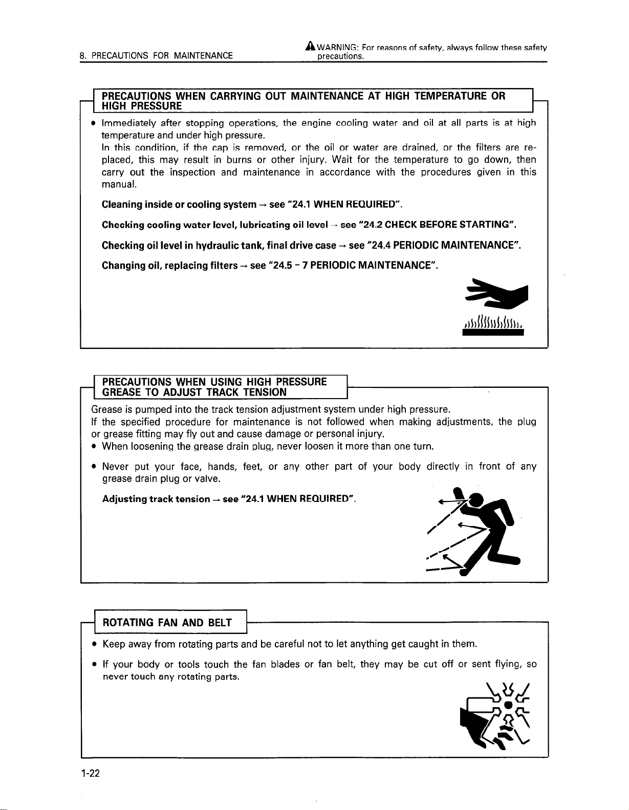
l If oil is leaking under high pressure from small holes, it is dangerous if the jet of high-press-
ure oil hits your skin or enters your eyes. Always wear safety glasses and thick gloves, and
use a piece of cardboard or a sheet of wood to check for oil leakage.
l If you are hit by a jet of high-pressure oil, consult a doctor immediately for medical atten-
tion.
1-21
Page 30
8. PRECAUTIONS FOR MAINTENANCE
AZ;~;NJG~FO~ reasons of safety, always follow these safety
PRECAUTIONS WHEN CARRYING OUT MAINTENANCE AT HIGH TEMPERATURE OR
HIGH PRESSURE
l Immediately after stopping operations, the engine cooling water and oil at all parts is at high
temperature and under high pressure.
In this condition, if the cap is removed, or the oil or water are drained, or the filters are replaced, this may result in burns or other injury. Wait for the temperature to go down, then
carry out the inspection and maintenance in accordance with the procedures given in this
manual.
Cleaning inside or cooling system + see “24.1 WHEN REQUIRED”.
Checking cooling water level, lubricating oil level
Checking oil level in hydraulic tank, final drive case
Changing oil, replacing filters
+ see “24.5 - 7 PERIODIC MAINTENANCE”.
+ see “24.2 CHECK BEFORE STARTING”.
+ see “24.4 PERIODIC MAINTENANCE”.
PRE>
GREASE TO ADJUST TRACK TENSION
Grease is pumped into the track tension adjustment system under high pressure.
If the specified procedure for maintenance is not followed when making adjustments, the plug
or grease fitting may fly out and cause damage or personal injury.
When loosening the grease drain plug, never loosen it more than one turn.
Never put your face, hands, feet, or any other part of your body directly in front of any
grease drain plug or valve.
Adjusting track tension + see “24.1 WHEN REQUIRED”.
ROTATING FAN AND BELT
l Keep away from rotating parts and be careful not to let anything get caught in them.
l If your body or tools touch the fan blades or fan belt, they may be cut off or sent flying, so
never touch any rotating parts.
1-22
Page 31

AWARNING: Failure to follow these safety precautions may
lead to a serious accident.
l Never dump waste oil in a sewer system, rivers, etc.
l Always put oil drained from your machine in containers. Never drain oil directly on the
ground.
l Obey appropriate laws and regulations when disposing of harmful objects such as oil, fuel,
coolant, solvent, filters, batteries, and others.
8. PRECAUTIONS FOR MAINTENANCE
INCORRECT A
1-23
Page 32

9. POSITION FOR ATTACHING SAFETY LABELS
Always keep these labels clean. If they are lost or damage,
attaching them again or replace them with a new label.
There are other labels in addition to the safety labels listed
as follows, so handle them in the same way.
Safety labels may be available in languages other than
English. To find out what labels are available, contact your
Komatsu distributor.
1-24
Page 33

9. POSITION FOR A-ITACHING SAFETY LABELS
Warnings before operating machine
(14X-98-l 1580)
A WARNING
improper operation and
maintenane can cause
serious injury or death.
Read manual and labels
before operation and
maintenance.
Follow instructions
and warnings in manual and
in labels on machine.
Keep manual in machine cab
near operator.
Contact komatsu distributor
for a replacement manual.
14X-98-11580 -
3. Warnings for leaving operator’s seat
(14X-98-l 1541)
A WARNING
To avoid hitting unlocked
operation levers, before
standing up from operator’s
seat, do the following :
0 Move steering and
directional lever neutral
and move SAFETY LOCK
LEVER (located left of
seat) to LOCK position.
0 Lower equipment to ground
and move SAFETY LOCK
LEVER(located right of
seat)to LOCK position.
Sudden and unwanted machine movement can cause
serious injuty or death.
14X-98-11541 _
Warnings before moving in reverse
(14X-98-l 1590)
A WARNING
8
9Y
Before moving machine or its
attachments :
0 Honk horn to alert people nearby.
l Be sure no one is on machine area
l Use spotter if necessary,
particularly if you are moving in
reverse.
Follow above even if equipped with
back-up alarm and mirrors.
0
14X-98-:1590 -
4. Warnings for hot water hazard
(14X-98-l 1531)
A WARNING
Hot water hazard.
To prevent hot water from
spurting out :
0 Turn engine off.
0 Allow water to cool.
0 Slowly loosen cap to
relieve pressure
before removing.
14X-98-11531 _
1-25
Page 34

9. POSITION FOR A-ITACHING SAFETY LABELS
5. Warnings for hot oil hazard
(14X-98-1 1521)
A WARNING
Hot oil hazard.
To prevent hot oil from
spurting out :
@Turn engine off.
@Allow oil to cool.
l Slowly loosen cap to
relieve pressure
before removing.
14X-98-11521 -
6. Warnings for adjusting track tension
(14X-98-11551)
rid WARNING 1
High pressure hazard at track
adjuster.
7. Warning for handling accumulator
(14X-98-l 1390)
8. Warning for handling battery
(14X-98-l 1370)
1 A WARNING ]
EXPLOSIVE GASES
0 Cigarettes, flames or sparks could cause
battery to explode.
0 Always shield eyes and face from battery.
0 Do not charge or use booster cables or
adjust post connections without proper
instruction and training.
l Keep vent caps tight and level.
POISON CAUSES SEVERE BURNS
Contains sulfuric acid.
0 Avoid contact with skin, eyes or clothing.
l In event of accident flush with water and
call a physician immediately.
l Keep out of reach of children.
14X-98-11370 -
When adjusting track tension,
never open plug more than one
turn.
Turning further could cause injury
from flying plug and grease.
See manual for adjustment
instructions.
14X-98-11551
l-26
Komatsu Ltd. Japan
i
9. Warning for ROPS,
(09620-30202)
ROLL-OVER PROTECTIVE STRUCTURi-
Distribitor before altering.
l ROP.S may provide less protection if it has been
*Always w&r seat-belt when moving.
2-3-b Akolota. Mlna,o-L”.ToLlo,J.pon
OPb20.30202
Page 35

OPERATION
Page 36

IO. GENERAL VIEW
10.1 GENERAL VIEW OF MACHINE
If directions are indicated in this section, they refer to the directions shown by the arrows in the
diagram below.
Machines equipped with cab
Cab
/
Lift cylinder
Machines equipped with canopy
Front u
Canopy
Rear
2-2
Page 37

10.
GENERAL VIEW
10.2
GENERAL
Machines equipped with cab
Air conditioner panel or
Steering and directional
Cigarette lighter
lever
VIEW
Fuel
control
OF CONTROLS AND GAUGES
Head
IamP
Heater
lever
\
switch
panel
\
Bear
tamp switch
Starting switch
I ^.
wow
p_
I=
\
-
/
=
I
=
.&_L
swrtcn
1
Deceleration pedal
Blade control
lever
Additional
working
Service
Engine
meter
temperature gauge temperature gauge
Engine water
temperature
caution lamp
water
pressure
caution lamp
Transmission oil
Transmission oil
temperature
caution lamp
2-3
Page 38

10. GENERAL VIEW
Machines equipped with canopy
Monitor panel specificaion
directional lever
Gear
Head lamp switch
Fuel control lever
Bear lamp switch
Service meter
\
Engine water Transmission
temperature
gauge
\
oil temperature
w-m
I
Deceleration pedal
Blade control
Fuel gauge
I
lever
2-4
A\ !_A
J
-) \\
i
Engine water
caution lamp
Engine bil pressure Transmission oil,
caution lamp
temperature
caution lamp
Page 39

Machines equipped with canopy
Gauge panel specification
Head lamo switch Rear IamD switch
Horn switch
Deceleration pedal
Blade control lever
Service meter
Engine water
temperature gauge
Charge lamp
Transmission oil
temperature gauge
Engine oil
pressure
caution lamp
Glow signal
2-5
Page 40

1 I. EXPLANATION OF COMPONENTS
The following is an explanation of the devices needed
operating
important
equipment and the meanings of the
the
the machine.
To carry out suitable
understand fully the methods of operating the
to
operations correctly and
displays.
Before reading the explanation of
below to check what
table
equipment is installed
components, please read
machine.
Equipment Section
Front panel
Switch panel (cab)
Switch panel (canopy)
Switches
No.
11.1.1
11.1.2
11.1.3
11.1.4
11.1.5
11.1.6
safely, it is
your
to
D65E-12
l-
D6E
Canopy
0
0
-
-
0
for
iP.
T-
-12
Cab
0
-
0
0
0
-
Canopy
0
0
-
0
D65EX-12
(-12
D65
c
t
c
Cab
0
-
0
0
0
-
Additional working lamp switch
Control levers and pedals
Fuel control lever
Steering and directional lever
Steering and directional lever
(with counterrotation turn)
Gear shift lever
Brake pedal
Deceleration pedal
Parking lever
Safety lever (For blade control lever)
Blade control lever
Power tilt dozer
Power tilt, power pitch dozer
Angle dozer
11.2 1
11.2 2
11.2 3
11.2 4
11.2 5
11.3 1
11.3 2
11.3 2
11.3 3
11.3 4
11.3 5
11.3 6
11.3 7
11.3 8
0
-
-
-
-
0
0
-
0
0
0
0
0
0
0
0
L
t
0
0
0
0
0
0
0
0
0
0
0
0
0
0
0
0
_
0
-
0
0
0
0
0
0
0
0
0
0
0
0
0
0
0
0
0
0
0
0
0
0
0
0
i
2-6
Page 41

11. EXPLANATION OF COMPONENTS
11.1 FRONT PANEL (METERS, LAMPS, SWITCHES)
11 .I .I
MONITOR PANEL
(MONITOR PANEL SPECIFICATION)
1. SERVICE METER
This meter shows the total operation hours of the ma-
chine. The service meter advances
- even if the machine is not traveling.
Set the periodic maintenance intervals using this display.
When the engineis running, the green pilot lamp 0 at the
top of the meters flashes to indicate that the meter is advancing.
Meter 0 will advance by 1 for each hour of operation regardless of the engine speed.
2. ENGINE WATER TEMPERATURE GAUGE
This gauge indicates the cooling water temperature.
When the indicator is in the white range during operation,
the water temperature is normal.
If the indicator moves from the white range into the red
range during operation, stop the machine immediately, run the
engine under no load at a midrange speed, and wait for the
indicator to go down to the white range.
After starting the engine, warm up it until the indicator
moves into the white range.
while the engine is running
r
I \ I
white
red
2-7
Page 42

11. EXPLANATION OF COMPONENTS
3. TRANSMISSION OIL TEMPERATURE GAUGE
This indicates the temperature of the transmission lubricat-
ing oil.
When the indicator is in the white range during operation,
the oil temperature is normal.
If the indicator moves from the white range into the red
range during operation, stop the machine, run the engine
under no load at a midrange speed, and wait for the indicator
to go down to the white range.
4. FUEL GAUGE
When the starting switch is turned ON, this gauge indi-
cates the amount of fuel in the fuel tank.
F indicates that the tank is full.
E indicates that there is less than 43 liters of fuel remaining in
the tank, so add fuel.
After each operation, be sure to fill up the fuel tank.
5. ENGINE WATER TEMPERATURE CAUTION LAMP
This warns of a rise in the temperature of the engine cool-
ing water.
If the lamp lights up, stop the machine, run the engine
under no load at a midrange speed, and wait for the indicator
of the engine water temperature gauge to go down to the
white range.
white
6. CHARGE LAMP
This lamp indicates malfunction of the alternator.
When the starting switch is turned ON, it will light up, but it
should go out when the engine speed rises.
If the lamp lights up during operation, stop the engine and
check the V-belt tension. If any abnormality is found, see “16.
TROUBLESHOOTING”.
7. ENGINE OIL PRESSURE CAUTION LAMP
This lamp warns that the engine lubricating oil pressure
has dropped. When the starting switch is turned ON, it will
light up.
When the lamp goes off after the engine is started, the oil
pressure is normal.
When the lamp lights up during operation, the oil pressure is
lower.
Immediately stop the engine and look for the cause. For de-
tails, see “16. TROUBLESHOOTING”.
8. GLOW SIGNAL LAMP
This indicates the electrical intake air heater is red-heated.
While preheating is being carried out with the glow switch,
the lamp lights up.
In the case of automatic preheating, the lamp goes out when
the preheating is completed.
In the case of manual preheating, the lamp goes out when
the glow switch is released.
0
0
0
u
-O-
m
0
Fvz
2-8
Page 43

9. TRANSMISSION OIL TEMPERATURE CAUTION LAMP
This warns of a rise in the temperature of the oil at the
transmission outlet port.
If the lamp lights up, stop the machine, run the engine
under no load at a midrange speed, and wait for the indicator
of the transmission oil temperature gauge to go down to the
white range.
10. MONITOR CAUTION LAMP
This lamp lights up if any of caution lamps 0, 8, 0, or @
light up. At the same time the alarm buzzer sounds.
11 MONITOR CAUTION CANCEL SWITCH
‘This switch is used to cancel monitor caution lamp @.
Press the switch to turn the monitor caution lamp out and to
stop the alarm buzzer.
11. EXPLANATION OF COMPONENTS
CANCEL
0
0
2-9
Page 44

11. EXPLANATION OF COMPONENTS
11 .I .2 GAUGE PANEL
(GAUGE PANEL SPECIFICATION)
1. SERVICE METER
This meter shows the total operation hours of the ma-
chine. The service meter advances while the engine is running
- even if the machine is not traveling.
Set the periodic maintenance intervals using this display.
Meter will advance by 1 for each hour of operation regardless of the engine speed.
2. ENGINE WATER TEMPERATURE GAUGE
This gauge indicates the cooling water temperature.
When the indicator is in the green range during operation,
the water temperature is normal.
If the indicator moves from the green range into the red
range during operation, stop the machine immediately, run the
engine under no load at a midrange speed, and wait for the
indicator to go down to the green range.
After starting the engine, warm up it until the indicator
moves into the green range.
2-l 0
Page 45

3. TRANSMISSION OIL TEMPERATURE GAUGE
This indicates the temperature of the transmission lubricat-
ing oil.
When the indicator is in the green range during operation,
the oil temperature is normal.
If the indicator moves from the green range into the red
range during operation, stop the machine, run the engine
under no load at a midrange speed, and wait for the indicator
to go down to the green range.
4. CHARGE LAMP
This lamp indicates malfunction of the alternator.
When the starting switch is turned ON, it will light up, but it
should go out when the engine speed rises.
If the lamp lights up during operation, stop the engine and
check the V-belt tension. If any abnormality is found, see “16.
TROUBLESHOOTING”.
5. ENGINE OIL PRESSURE CAUTION LAMP
This lamp warns that the engine lubricating oil pressure
has dropped. When the starting switch is turned ON, it will
light up.
When the lamp goes off after the engine is started, the oil
pressure is normal.
When the lamp lights up during operation, the oil pressure is
lower.
Immediately stop the engine and look for the cause. For de-
tails, see “16. TROUBLESHOOTING”.
11. EXPLANATION OF COMPONENTS
6. GLOW SIGNAL
This indicates the electrical intake air heater is red-heated.
When holding the starting switch key at the HEAT position,
this signal glows red after 15 - 45 seconds.
When releasing the key, the key will return to the OFF position and the signal will go off.
e
+z
Q
2-11
Page 46

11. EXPLANATION OF COMPONENTS
11 .I .3 AIR CONDITIONER PANEL
(MACHINES EQUIPPED WITH CAB,
AIR CONDITIONER)
For details of handling switches 0 to @I below, see “11 .I6
HANDLING AIR CONDITIONER”.
1. FRESHIRECIRC SELECTOR LEVER
This changes the air intake port used when cooling or
heating.
0
RECIRC ( @ )
Turn the switch normally to this position when strong cool-
ing is needed. In this position, no ventilation or pressurizing is
carried out.
0
FRESH (a) takes in outside air.
This is the standard position for cooling and heating.
In this position, fresh air is brought in from outside to
carry out ventilation. In addition, the inside of the cab is
pressurized to prevent the entry of dust.
2. AIR CONDITION SWITCH
When the switch is pressed and the blue lamp lights up,
the cooling functionis actuated. Use this switch for cooling or
dehumidifying.
uses the air inside the cab.
2-l 2
Page 47

3. BLOWER SWITCH
This acts as the wind flow control switch and main switch
when cooling or heating.
l The air flow can be set to three stages: 1 (LOW) + 2
(MEDIUM) + 3 (HIGH).
l If the switch is set to 0, the power is switched off and the
air conditioner stops.
4. TEMPERATURE CONTROL LEVER
This is used to control the temperature for cooling or heat-
ing.
l When the temperature control lever is moved to the right,
the temperature of the air coming from the vents becomes
lower.
(The water valve is closed and the heating function is
stopped.)
l When the temperature control lever is moved to the left,
the temperature of the air coming from the vents becomes
higher.
(The water valve is opened and the heating function is
started.)
11. EXPLANATION OF COMPONENTS
@
I
Fvm
F177M
5. STARTING SWITCH
This switch is used to start the engine.
OFF ( @ ) position:
At this position, the starting switch key can be inserted or
removed. When the switch is turned to this position, the elec-
trical circuits are switched off.
Do not the starting switch key at the OFF position while
the engine is running.
ON position :
In this position, electric current flows in the charging and
lamp circuits.
Keep the starting switch key at the ON position while the
engine is running.
START ( 0) position:
This is the position to start the engine. Hold the key at
this position while cranking. Release the key immediately after
the engine has been started. The key will return to ON position when released.
OFF
2-13
Page 48

11. EXPLANATION OF COMPONENTS
11 .I .4 HEATER PANEL
(MACHINES EQUIPPED WITH CAB, HEATER)
For details of handling switches 0 to @ below, see “11.17
HANDLING HEATER”.
1. FRESH/RECIRC SELECTOR LEVER
This changes the air intake port used when cooling or
heating.
l RECIRC ( @j ) uses the air inside the cab.
Turn the switch normally to this position when strong cool-
ing is needed. In this position, no ventilation or pressurizing is
carried out.
l FRESH (5) takes in outside air.
This is the standard position for cooling and heating.
In this position, fresh air is brought in from outside to
carry out ventilation. In addition, the inside of the cab is
pressurized to prevent the entry of dust.
2. BLOWER SWITCH
This acts as the wind flow control switch and main switch ’
when cooling or heating.
l The air flow can be set to three stages: 1 (LOW) -+ 2
(MEDIUM) + 3 (HIGH).
l If the switch is set to 0, the power is switched off and the
heater stops.
2-14
Page 49

3. TEMPERATURE CONTROL LEVER
This is used to control the temperature for heating.
l When the temperature control lever is moved to the right,
the temperature of the air coming from the vents becomes
lower.
l When the temperature control lever is moved to the left,
the temperature of the air coming from the vents becomes
higher.
11. EXPLANATION OF COMPONENTS
4. STARTING SWITCH
This switch is used to start the engine.
OFF ( @) position:
At this position, the starting switch key can be inserted or
removed. When the switch is turned to this position, the elec-
trical circuits are switched off.
Do not the starting switch key at the OFF position while
the engine is running.
ON position:
In this position, electric current flows in the charging and
lamp circuits.
Keep the starting switch key at the ON position while the
engine is running.
START ( 0 ) position:
This is the position to start the engine. Hold the key at
this position while cranking. Release the key immediately after
the engine has been started. The key will return to ON position when released.
OFF
2-15
Page 50

11. EXPLANATION OF COMPONENTS
11 .I .5 SWITCH PANEL
(MACHINES EQUIPPED WITH CAB)
1. HEAD LAMP SWITCH
This lights up the head lamps.
OFF position: Lamps are out
ON position: Lamps light up
2. REAR LAMP SWITCH
This lights up the rear lamps.
OFF position: Lamps are out
ON position: Lamps light up
OFF ON
lJ
2-l 6
Page 51

3. GLOW SWITCH
This actuates the electrical heater to warm up the engine
intake air.
OFF position: The preheating is not actuated.
AUTO position : AUTO preheating is actuated. The length of
the preheating time varies according to the ambient temperature when the ambient temperature is below approx. -5°C.
I position: This is used when AUTO preheating is not enough
to start the engine in cold weather simply with the glow
switch at the AUTO position.
When the switch is released, it will return to the AUTO position.
II position: This is used when carrying out preheating ma-
nually without using AUTO preheating.
When the switch is released, it will return to the OFF position.
11. EXPLANATION OF COMPONENTS
2-17
Page 52

11. EXPLANATION OF COMPONENTS
11 .I .6 SWITCH PANEL
(MACHINES EQUIPPED WITH CANOPY)
1. HEAD LAMP SWITCH
This lights up the head lamps.
OFF position: Lamps are out
ON position: Lamps light up
2. REAR LAMP SWITCH
This lights up the rear lamps.
OFF position: Lamps are out
ON position: Lamps light up
2-l 8
Page 53

-
11. EXPLANATION OF
COMPONENTS
3. GLOW
This
intake
OFF position: The preheating is
AUTO
the
preheating time varies
ture when
I position:
SWITCH
(MONITOR PANEL SPECIFICATION)
actuates the electrical
air.
position:
AUTO
the ambient temperature
This
is used when AUTO preheating is not
heater to warm up the
not actuated.
preheating
is
actuated. The length of
according to the ambient tempera-
is below approx. -5°C.
engine
enough
to start the engine in cold weather simply with the glow
switch
When the switch
II
nually
When the switch is released, it will return to the
at
the AUTO position.
is
released, it will return to the AUTO position.
position:
This is used when carrying out preheating ma-
without using AUTO preheating.
OFF
position.
4. STARTING SWITCH
This switch is used to start the engine.
1 Monitor
panel specification
OFF ( @ ) position:
At this position, the starting switch key can
be inserted or
removed. When the switch is turned to this position, the electrical circuits are switched off.
Do not the starting switch key at the OFF position while
the engine is running.
ON position:
In this position,
electric current flows in the charging and
lamp circuits.
Keep the starting switch key at the ON position while the
engine is running.
START ( 0) position:
This is the position to start the engine. Hold the key at
this position while cranking. Release the key immediately after
the engine has been started. The key will return to ON position when released.
HEAT ( 53 ) position (Gauge panel specification):
0
Turn the starting switch key to the HEAT position when
starting in cold weather.
If the key is held at the HEAT position, the electrical heater
is heated and the glow signal lights up or glows red. If the
glow signal flashes or glows red, release the key immediately.
When the key is released, it will return to OFF, so turn it im-
mediately to the START position to start the engine.
Gauge panel specification
HE,AT OFF
I
-START
F16262
2-l 9
Page 54

11. EXPLANATION OF COMPONENTS
1 I, 2 SWITCHES
1. HORN BUTTON
Press the button in the middle of the steering and direc-
tional lever to sound the horn.
2. ROOM LAMP SWITCH (MACHINES EQUIPPED WITH CAB)
This lights up the room lamp.
ON position: Lamp lights up
OFF position: Lamp is out
3. CIGARETTE LIGHTER (MACHINES EQUIPPED WITH CAB)
This is used to light cigarettes.
When the cigarette lighter is pushed in, it will return to its
original position after a few seconds, so take it out to light
your cigarette.
NOTICE
This cigarette lighter is 24V. Do not use it as the power
source for 12 V equipment.
2-20
Page 55

4. WIPER SWITCH (MACHINES EQUIPPED WITH CAB)
This activates the wipers.
The wiper switches are as follows.
0 Left door
0 Front window
0 Right door
0 Rear window
This is also used as the window washer switch.
The switch is operated as follows.
l
Window washer only
Keep the switch pressed to the OFF position to spray out
water.
11. EXPLANATION OF COMPONENTS
l Wiper only
If this is switched on, the wiper will start.
l
Wiper and window washer
If this is kept pressed to the ON position while the wiper is
working, water will be sprayed out.
5.
ADDITIONAL WORKING LAMP SWITCH
(MACHINES EQUIPPED WITH CAB)
This is used to turn on the additional working lamp.
Head lamp switch
0
Rear lamp switch
0
Push in the direction of the arrow to turn on the lamps.
I
I
2-21
Page 56

11. EXPLANATION OF COMPONENTS
11.3
CONTROL LEVERS AND PEDALS
1. FUEL
@ Engine stop
@I Low idling position: Pull the lever
@I
CONTROL LEVER
This lever is used to
position: Push the
idling position: Pull the lever fully
High
control the
tion 0 until you feel the operating
force falls off.
engine speed and output.
lever forward fully.
from engine stop posi-
low idling position.
from
2-22
Page 57

2. STEERING AND DIRECTIONAL LEVER (D65E, P)
This lever is used to switch between forward and reverse
and to steer the machine.
Forward-reverse shifting
a: FORWARD
@: REVERSE
@x NEUTRAL
Push the lever forward, the machine will move off forward.
Pull the lever backward, the machine will move off in reverse.
Steering
G: LEFT TURN
@: RIGHT TURN
If the lever is operated to the forward or reverse position
and is moved partially in the direction of turn, the steering
clutch is disengaged and the machine turns gradually.
If the lever is moved more, the steering brake is applied and
the machine will turn on the spot.
REMARK
If the lever is released when steering the machine, the
lever will return to the 0 position or the 0 position and the
machine will be returned to straight movement.
If you support the lever guide with your hand when steering, the turning operation will be easier.
11. EXPLANATION OF COMPONENTS
Lever guide
2. STEERING AND DIRECTIONAL LEVER (D65EX, PX)
This is used when shifting between forward and reverse,
and when steering or carrying out counterrotation turns.
Forward-reverse shifting
@: FORWARD
0: REVERSE
@: NEUTRAL
Push the lever forward, the machine will move off forward.
Pull the lever backward, the machine will move off in reverse.
__
Steering
0: LEFT TURN
8: RIGHT TURN
If the lever is operated to the forward or reverse position
and is moved partially in the direction of turn, the machine
turns gradually.
If the lever is operated more in the direction of turn, the
machine will turn more sharply.
REMARK
If the lever is released when steering the machine, the
lever will return to the 0 position or the 0 position and the
machine will be returned to straight movement.
If you support the lever guide with your hand when steer-
ing, the turning operation will be easier.
Lever guide
I
2-23
Page 58

11. EXPLANATION OF COMPONENTS
l Counterrotation turn
-A
If the steering and directional lever is not operated
fully to the forward or reverse position and the lever
is operated to turn the machine, the machine may
carry out a counterrotation turn, so do not try to turn
the machine with the lever partially operated.
When carrying out a counterrotation turn, if the load
is not equal on the left and right sides, the machine
may carry out a pivot turn, so check the ground con-
ditions and be careful not to hit any obstacles.
If the steering and directional lever is operated partially in
the direction of turn with the lever at the 0 position, the
left and right tracks will rotate in opposite directions and
the machine will turn
ing lever is operated
tion turn will increase.
3. GEAR SHIFT LEVER
This lever changes the transmission gear range. There
are three ranges, and the gear can be shifted simply by
moving the gear shift lever to the desired position.
0 First speed
@Second speed
@Third speed
WARNING
smoothly on the spot. If the steer-
fully, the speed of the counterrota-
I
4. BRAKE PEDAL
WARNING
A
Do not place your foot on this pedal unnecessarily.
Depress the pedal to apply the right and left brakes.
5. DECELERATION PEDAL
-A
Do not place your foot on this pedal unnecessarily.
When passing over the top of a hill or when a load is
dumped over a cliff, the load is suddenly reduced, so
there is danger that the travel speed will also increase suddenly. To prevent this, depress the decelerator pedal to reduce the travel speed.
This pedal is used when reducing the engine speed.
When switching between forward and reverse, or when
stopping the machine, use this pedal to reduce speed.
WARNING
-I
2-24
Page 59

6. PARKING LEVER
When the machine is parked, always set the parkmg
lever to the LOCK position.
This lever is used to apply the parking brake.
REMARK
If the parking lever is set to the LOCK position when the
directional and steering lever is at the forward or reverse position, the directional and steering lever is automatically returned to the N position.
When starting the engine, check that the parking lever is
at the LOCK position. If it is not at the LOCK position, the engine cannot be started.
7. SAFETY LEVER (For blade control lever)
WARNING
A
When leaving the operator’s compartment, set the
safety lever securely to the LOCK position. If the control lever is not locked, and it is touched by mistake,
this may lead to a serious accident.
If the safety lever is not placed securely in the LOCK
position, the control lever may not be properly locked.
Check that the situation is as shown in the diagram.
When parking or servicing the machine, be sure to
lower the blade and set the safety lock in the LOCK
position.
11. EXPLANATION OF COMPONENTS
This is the locking device of blade control lever.
When the safety lever is set to the LOCK position, the
TILT, LOWER, and FLOAT controls are locked.
If it is set to the LOCK position when the blade control lever
is at the FLOAT position, the blade control lever is automati-
cally returned to the HOLD position.
2-25
Page 60

11. EXPLANATION OF COMPONENTS
8. BLADE CONTROL LEVER
(POWER TILTDOZER)
This lever is used to raise or tilt the blade.
Lifting control
@ RAISE : ( & )
@ HOLD :(A)
Blade is stopped and held in this position.
@ LOWER: ( + )
@ FLOAT : (_ )
%
Blade will move freely according to external force.
REMARK
l When released from FLOAT position, this lever will not re-
turn to HOLD position, so it must be moved back by hand.
l When starting the engine, set the blade control lever to
the HOLD position.
If it is at the FLOAT position, the engine will not start.
Tilting control
@ LEFT TILT : ( I&-, )
@ RIGHT TILT : ( & )
I
Right tilt
I
Left tilt
107032
2-26
Page 61

8. BLADE CONTROL LEVER
(FOR POWER TILT, POWER PITCH DOZER)
This carries out the blade lift, tilt, and pitch operations.
Lifting control
@ RAISE : ( &_ )
@ HOLD : ( A )
Blade is stopped and held in this position.
@ LOWER : ( 4 )
@ FLOAT : (
%
)
Blade will m=e freely according to external force.
REMARK
l When released from FLOAT position, this lever will not re-
turn to HOLD position, so it must be moved back by hand.
l When starting the engine, set the blade control lever to
the HOLD position.
If it is at the FLOAT position, the engine will not start.
Tilting control
@ LEFT TILT : ( !& )
@ RIGHT TILT : ( 4 )
11. EXPLANATION OF COMPONENTS
Right tilt
Pitch control
8 Rear pitch: Small blade cutting angle
@ Forward pitch: Large blade cutting angle
First set the lever to the neutral position, then keep switch
0 in the center of the
knob pushed down and carry out the
tilt operation to change tl ie cutting angle of the blade.
Precautions when using pitch control
When operating the pitch, the cutting angle is shown by
the gauge bar on the right pitch cylinder. When using the
pitch operation, the tilt operation changes as follows.
Pitch condition 1 Tilt operation 1
Max. forward pitch
Forward pitch
Standard pitch
Rear pitch
Max. rear pitch
Only left tilt
operation is possible
Both left and right
tilt operations are
possible
Only right tilt
operation is possible
Amount of tilt
Max. 890 mm
Compared with standard:
LEFT tilt is LARGER
RIGHT tilt is SMALLER
445 mm (both left and right)
Compared with standard:
LEFT tilt is SMALLER
RIGHT tilt is LARGER
Max. 890 mm
Forward pitch
Pitch gauge \
I
Left tilt
*.
Rear pitch
F07a%
I
\
2-27
Page 62

11. EXPLANATION OF COMPONENTS
8. BLADE CONTROL LEVER (FOR ANGLEDOZER)
This lever is used to raise the blade.
Lifting control
@ RAISE : ( JJ_ )
@ HOLD : ( A )
Blade, is stopped and held in this position.
@ LOWER : ( 4 )
@ FLOAT : (
%
)
Blade will m=e freely according to external force.
REMARK
l When released from FLOAT position, this lever will not re-
turn to HOLD position, so it must be moved back by hand.
l When starting the engine, set the blade control lever to
the HOLD position.
If it is at the FLOAT position, the engine will not start.
2-28
Page 63

11.4 FUSE BOX
NOTICE
Before replacing a fuse, be sure to turn off the starting
switch.
If the fuse blows again immediately after it is replaced,
please contact your Komatsu distributor to have the system inspected.
The fuses protect the electrical equipment and wiring from
burning out.
If the fuse becomes corroded, or white powder can be
seen, or the fuse is loose in the fuse holder, replace the fuse.
Replace a fuse with another of the same capacity.
l Chassis
When the battery cover is opened, two fuse boxes can be
found inside.
l Cab (machines equipped with cab)
It is installed at the bottom of the overhead panel.
11. EXPLANATION OF COMPONENTS
Fuse box @
11.4.1 FUSE CAPACITY AND CIRCUIT NAME
Fuse box @
FUSE CAPACITY
No.
0
0
0 I
0
0
20A
IOA
I
IOA
IOA
IOA Back-up alarm
Head lamp, Rear lamp
Chassis power source
I
/ Engine control system
Horn
Fuse box @
FUSE CAPACITY
No.
0
0
0
@
0
IOA Cab radio
IOA
20A
- _
IOA
Power pitch selector
Air conditioner
Chassis power source
Fuse box @ (machines equipped with cab)
FUSE CAPACITY
No.
0
0
0
@
0
6%
IOA Radio memory
20A
IOA
IOA Right door wiper
10A
IOA Left door wiper
Radio, Lamps, Cigarette lighter
Rear wiper
Front wiper
CIRCUIT NAME
CIRCUIT NAME
CIRCUIT NAME
Fuse box @I
Fuse box 0
2-29
Page 64

11. EXPLANATION OF COMPONENTS
11.5 GREASE PUMP HOLDER
This is inside the left engine side cover.
Fit the grease pump to the holder when it is not being used.
11.6 SHOVEL HOLDER
This can be used for storing a shovel with a rounded
blade.
l Method of installing
1. Fix the shovel with stopper 0 and holder 0.
2. Tighten with adjustment nut 0 so that the shovel does not
move.
11.7 DOOR-OPEN
LOCK
(MACHINES EQUIPPED WITH CAB)
Use this when your want to keep the door held open.
1. Push the door against the door catch. The door will be
held by the door catch.
2. To release the door, move lever 0 inside the cab to the
front of the cab. This will release the catch.
NOTICE
l When keeping the door open, fix it securely to the catch.
l Always close the door when traveling or carrying out
operations. Leaving the door open will cause the door to
break.
l Keep the door locked open securely.
The door may swing closed because of the vibraion.
/\
I
Fll8i
2-30
Page 65

11.8 SASH GLASS INTERMEDIATE LOCK
(MACHINES EQUIPPED WITH CAB)
Do not stick your head or hand out of the window during
Even when the glass is locked, it may move bcause of
shock if the machine is started or stopped suddenly.
When carrying out operations with the cab sash glass
open, use this block to prevent the glass from moving.
l When the lever is at the FREE position, the glass can be
opened or closed.
l When the lever is moved to the LOCK (up or down) posi-
tion, the glass is fixed in position.
l If the glass is not held securely, set the lever in the FREE
position and rotate clockwise to strengthen the holding I
power.
l To reduce the holding power, turn counterclockwise.
11. EXPLANATION OF COMPONENTS
NOTICE
Always close the window when traveling or carrying out
operations. Leaving the window open will cause the window
to break.
11.9 CAP WITH LOCK
Lock is installed to the fuel tank filler cap.
Open and close locking cap as follows:
a
To open the cap
Insert the starting switch key into the key hole on the cap.
1.
Insert the key as far as it will go. If the key is turned be-
fore it is inserted all the way to the shoulder, it may
break.
Turn the key clockwise, align the match mark on the cap
2.
with the rotor groove, then remove the cap.
a
To lock the cap.
Turn the cap into place.
1.
2.
Turn the key counterclockwise and take the key out.
LOCK
OPEN
Shoulder
2-31
Page 66

EXPLANATION OF COMPONENTS
11.
11 .I0 HOT AND COOL BOX
(MACHINES EQUIPPED WITH CAB)
This is
warm or cool three
This is interconnected
heating,
drinks.
at the top of the front
it warms up the
canned
drinks.
with the
drinks; during cooling, it cools to
panel. It
air conditioner: During
11 .I1 DOOR POCKET
(MACHINES EQUIPPED WITH CAB)
can
be
used to
the
These are on the inside of the
used for keeping
be
can
other heavy objects in the pocket. If
turn three clips 0, remove the pocket and wash it.
things. However,
left and right doors, and
do not put tools or
the pocket becomes dirty,
11 .I 2 ASHTRAY
(MACHINES EQUIPPED WITH CAB)
This is on the left side of the operator’s seat.
Always make sure that you extinguish the cigarette before
closing the lid.
11.13 TOOL
This is used for keeping the tools.
BOX
2-32.
Page 67

11. EXPLANATION OF
COMPONENTS
11 .I4
USING
CAR RADIO
(MACHINES EQUIPPED WITH CAB, CAR RADIO)
11.14.1 EXPLANATION
OF PARTS
1. POWER SWITCH/VOLUME CONTROL KNOB
(PUSH ON/VOL)
Push this knob to switch the radio on. The lighting in dis-
play area 0 will light up and the frequency will be displayed.
Press again to switch the power off.
Turn the knob clockwise to increase the sound, and
counterclockwise to reduce it.
2. TONE CONTROL KNOB (TONE)
Turn this knob clockwise from the center position to em-
phasize the high sounds, and counterclockwise to emphasize
the low sounds.
2-33
Page 68

Il. EXPLANATION OF COMPONENTS
3. DISPLAY BUTTON (DISP)
If the display button is pressed when the radio is being
used, the frequency of the station being listened to is displayed for 5 seconds.
4. TUNING/HOUR, MIN ADJUSTMENT BUTTON (TUNE)
This is used to select the station or change the frequency.
If the station UP button A is pressed, the frequency will
go up by 9 kHz each time it is pressed; if the station DOWN
button V is pressed, the frequency will go down 9 kHz each
time it is pressed.
If these buttons are kept pressed for more than 2 seconds,
the station will be selected automatically.
When adjusting the time, these change the hour display and
minute display.
5. PRESET BUTTON (I, 2, 3, 4, 5, 6)
These buttons can be used to program the desired broad-
casting stations. It is then possible to select the station at a
touch.
6. TIME ADJUSTMENT BUTTON (T.ADJ)
Press this button to adjust the time.
7. TIME RESET BUTTON (RESET)
Press this button to reset to the exact hour.
8. DISPLAY
This displays the frequency, time, and preset symbols.
2-34
Page 69

11.14.2 METHOD OF USE
Method of setting preset buttons
Press power switch 0. The frequency is displayed in display area 0.
Use selector button 0 ( A or V) to adjust to the desired
frequency.
Choose a preset button to use for this station, and keep it
pressed for at least 2 seconds to program the button to
that frequency.
When the sound suddenly disappears and appears again,
the button is programmed, and the preset number is
shown in display area 0.
After programming the button, press the preset button and
release it within approx. 2 sec. The station programmed to
that button will be selected for reception.
It is possible to program one station for each preset but-
ton.
11. EXPLANATION OF COMPONENTS
Method of manual tuning
Press the tuning button lightly to adjust to the desired fre-
quency. Each time the button is pressed, the frequency
will change by 9 kHz.
A button: Select station at higher frequency
v button: Select station at lower frequency
Method of automatic tuning
Keep the tuning button pressed for at least 2 seconds and
then release it. When reception from a broadcasting station is picked up, the selector will automatically stop at
that position.
When searching for the next station, keep the selector but-
ton pressed again for at least 2 seconds.
A button: Select station at higher frequency
V button: Select station at lower frequency
If the reception is weak, and stations are not found, adjust
the frequency manually to select the desired station.
2-35
Page 70

11. EXPLANATION OF COMPONENTS
Adjusting time
1. Keep T.ADJ button 0 pressed, and press H button 0.
The hour display will change, so when it reaches the correct hour, release the button.
2. Keep T.ADJ button 0 pressed and press M button 0.
The minute display will change, so when it reaches the
correct time, release the button.
Method of using RESET button
If RESET button 0 is pressed at the same time as the
time signal or standard time, the display will return immedi-
ately to the exact hour (0 hour 00 min).
If the display is 01 - 29 min, the display will go back to
0 min.
If the display is 30 - 59 min, the display will advance to
0 min.
[Example]
IO:29 -f IO:00 (return to exact hour)
IO:30 - II:00 (advances to exact hour)
11.14.3 PRECAUTIONS WHEN USING
l For safety reasons, when operating keep the sound to a
level where you can enjoy the sound but still hear the
sound from outside vehicles.
l If water gets inside the speaker case or car radio (auto
tuning), it may cause a serious problem, so do not let
water get on these parts.
l Do not wipe the knobs or buttons or any other parts with
any solvent such as benzene or thinner. Always wipe with
a soft dry cloth (in cases of extreme dirt, use alcohol on
the cloth).
11 .I 4.4 SPECIFICATION
Tuning method: PLL synthesizer method
Reception frequency: 522 kHz - 1629 kHz
Intermediate frequency: 450 kHz
Rated output: 3 W
Max. output: 5 W
Voltage: DC26.4V (21.6V, 31.2V) (-) ground
Current: Max. 2A
Outside dimensions: Width 178 mm, height 50 mm,
depth 110 mm
Weight: 640 g
2-36
Page 71

11 .I5 USING CAR STEREO
(MACHINES EQUIPPED WITH CAB, CAR STEREO)
11.15.1 EXPLANATION OF PARTS
11. EXPLANATION OF COMPONENTS
1. POWER/VOLUME CONTROL KNOB (ONIVOL)
When this knob is turned clockwise, the power for the
radio comes on, the lighting for display area 0 lights up, and
the frequency is displayed. If the knob is turned further clockwise, the sound becomes louder.
Turn the knob counterclockwise to reduce the sound.
When the knob is turned fully counterclockwise, the power is
turned off.
2. AUTOMATIC TUNING BUTTON (SEEK PUSH)
This is used to select the station or change the frequency.
When the center of the knob is pressed, it will move to a
higher frequency, and when reception from a broadcasting
station is picked up, the selector will automatically stop at that
position.
2-37
Page 72

11. EXPLANATION OF COMPONENTS
3. MANUAL TUNING BUTTON (TUNE)
This is used to select the station or change the frequency.
If the station up button A is pressed, the frequency will go
up; if the station down button V is pressed, the frequency
will go down.
AM
A part: The frequency goes up by 9 kHz each time the button
is pressed.
v part: The frequency goes down by 9 kHz each time the but-
ton is pressed.
FM
A’part: The frequency goes up by 0.1 MHz each time the button is pressed.
v part: The frequency goes down by 0.1 MHz each time the
button is pressed.
REMARK
If the button is held down, the frequency will change con-
tinuously.
4. PRESET BUTTONS (I, 2, 3, 4, 5, 6)
These buttons can be used to program the desired broadcasting stations. It is then possible to select the station at a
touch.
5. TONE ADJUSTMENT KNOB (TONE)
Press this knob and it will spring out. Then turn the knob
to adjust the tone.
Turn this knob clockwise from the center position to em-
phasize the high sounds, and counterclockwise to emphasize
the low sounds.
After completing the adjustment, push the knob back in.
r
2-38
Page 73

6. LEFT/RIGHT VOLUME ADJUSTMENT KNOB (BAL)
Press this knob and it will spring out. Then turn the knob
to adjust the tone.
Turn this knob clockwise, the volume from the R.H.
speaker increases. When turned counterclockwise, the volume
from the L.H. speaker increases.
After completing the adjustment, push the knob back in.
7. AM/FM SELECTOR BUTTON (BAND)
Each time this button is pressed, it changes between AM
and FM.
8. DISPLAY AREA
AM/FM, the frequency, and preset symbols are displayed
here. When a cassette is being used, it displays the direction
of play for the cassette.
11. EXPLANATION OF COMPONENTS
I,
/ [[Z-J]]
\ I\
9. TAPE EJECT BUTTON ( & )
This is used to eject the cassette tape from the car stereo.
Press this button and the cassette tape is ejected.
10. CASSETTE TAPE INSERTION PORT
Insert the cassette tape here. When the cassette tape is
set in the insertion port, it is installed inside the car stereo.
11. PROGRAM SELECTION, FAST FORWARD ( - )/
REWIND ( - ) BUTTON
When the U - M button is pressed, the tape is fast for-
warded, and when the “ - II button is pressed, it is wound.
To stop the tape, press the REWIND button lightly when
fast forwarding and press the FAST FORWARD button lightly
when rewinding.
If both the “- U button and fl - n button are pressed
at the same time, the direction of the tape will be reversed.
,
\
I-1
\
,
F17834
2-39
Page 74

11. EXPLANATION OF COMPONENTS
.15.2 LISTENING THE RADIO (AM/FM)
11
Turn power switch 0 clockwise to turn on the power.
1.
Check that display area 0 lights up and that letters are
displayed.
2.
Press AM/FM selector button 0 to select either AM or FM.
Press either automatic tuning button 0 or manual tuning
3.
button 0 to set to the desired frequency.
If the desired station frequency is set to preset button 8,
press preset button 0 to select the station.
REMARK
To receive a station where the signal is weak, press the
manual tuning button to adjust the frequency.
4. Adjust the volume, tone, left/right balance as desired.
5. To stop the radio, turn power switch 0 completely
counterclockwise to turn off the power. When the power is
turned off, the display in display area 0 goes out.
Method of presetting
1. Press automatic tuning button 0 or manual tuning button
0 to set to the desired frequency.
2. Choose a preset button 0 to use for this station, and keep
it pressed for at least 2 seconds to program the button to
that frequency.
When the sound suddenly disappears and appears again,
the button is programmed, and the preset number is
shown in display area 0.
After programming the button, press the preset button and
release it within approx. 2 sec. The station programmed to
that button will be selected for reception.
It is possible to program one station for each preset button.
2-40
Page 75

11 .I53 LISTENING TO CASSETTE TAPE
Turn power switch 0 clockwise to turn on the power.
1.
Check that display area 0 lights up and that letters are
displayed.
Set the cassette tape into insertion port @ and insert it
2.
into the car stereo. The direction of play of the tape is displayed in display area 0, and the tape plays.
Find the beginning of the tape as follows.
3.
l
Fast forward: Press fast forward button 0.
0
Rewind: Press rewind button 0.
0
Change direction of play (change between A side and B
side of cassette tape): Press fast forward button 0 and rewind button 0 at the same time.
Adjust the volume, tone, left/right balance as desired.
4.
When stopping the tape, press tape eject button 8 and
5.
remove the cassette tape. After removing the tape, turn
power switch @ completely counterclockwise to turn off
the power. When the power is turned off, the display in
display area 0 goes out.
11. EXPLANATION OF COMPONENTS
11.15.4 PRECAUTIONS WHEN USING
If the head is dirty, clean it with a head cleaning tape.
Never touch the head with a magnet, screwdriver, or any
other hard object.
Use a pencil to wind the tape to the outside to remove any
slack.
When not listening to the cassette tape, always remove it.
Put the tape in its case. Do not keep the tape in any of
the following places.
On top of the instrument panel
Any place where it is exposed to direct sunlight
Any place that is excessively humid
Any place that is excessively dusty
Any place where there is a strong magnetic field (near a
speaker, etc.)
Any place where there is high temperature (near the car
heater, etc.)
Use a C-60 (60 minute) tape. Avoid using longer tapes as
far as possible. In particular, do not use C-120 (120
minute) tapes. These tapes easily get caught up in the machine.
When replacing the fuse, always use a 5A fuse.
Do not put anything except a cassette tape in the tape insertion port.
When cleaning, wipe off the dirt with a dry cloth. Never
use any organic solvent such as thinner or benzene.
2-41
Page 76

11. EXPLANATION OF COMPONENTS
11 .I 5.5 SPECIFICATIONS
Radio
l FM
Reception frequency: 87.9 - 107.9 MHz
Intermediate frequency: 10.7 MHz
Sensitivity: 5 dBpEMF
S/N ratio: Min. 55 dB (stereo)
Min. 60 dB (monaural)
Distortion factor (1 kHz): Max. 0.5% (stereo)
Max. 0.2% (monaural)
Separation (1 kHz): Min. 30 dB
Frequency characteristics: 20 - 15000 Hz
l AM
Reception frequency: 531 - 1602 kHz
Intermediate frequency: 450 kHz
Sensitivity: 28 dBp EMF
S/N ratio: Min. 50 dB
Distortion factor: Max. 0.5%
Tape
Tape: 4 track, 2 channel, compact cassette tape
Wow & Flutter: Max. 0.25% (WRMS)
S/N ratio: Min. 50 dB
Cross talk: Min. 40 dB
Frequency characteristics: 30 - 12000 Hz
Others
Max. output: 15 W + 15 W
Voltage: DC 24V (22V - 32V)
Current: 5A (at max. output)
Speaker impedance: 4Q x 2
Outside dimensions: Width 178 mm, height 50 mm,
depth 125 mm
Weight: 1.4 kg
2-42
Page 77

11 .I 6 HANDLING AIR CONDITIONER
(MACHINES EQUIPPED WITH CAB)
11.16.1 COOLING OPERATION
When the cooling operation is carried out, the inside of
the cab is cooled, and at the same time the drinks inside the
hot and cool box can be cooled.
Cooling (RECIRC)
When the control switch and lever are ooerated as shown
in the diagram, a cool breeze is sent out.
Use this position when strong cooling is needed.
l Press switch 0.
l Place levers @ and @ in the position shown in the diag-
ram.
l Set switch 0 to the desired position.
Cooling (FRESH)
If the air inside the cab is no longer fresh, set FRESH/RECIRC selector lever 0 to FRESH to bring in fresh air. Keep the
other switches at the same positions as for cooling (RECIRC).
In this position, the inside of the cab is pressurized to prevent the entry of dust.
11. EXPLANATION OF COMPONENTS
REMARK
If the cooling effect is reduced, set FRESH/RECIRC selector
lever 0 to RECIRC again. This increases the cooling effect.
2-43
Page 78

11. EXPLANATION OF COMPONENTS
11 .I 6.2 HEATING OPERATION
When the heating operation is carried out, the inside of
the cab is heated, and at the same time the drinks inside the
hot and cool box can be heated.
Heating (RECIRC)
When the control switch and lever are operated as shown
in the diagram, warm air is sent out. Use this position when
strong cooling is needed.
l Place levers 0 and @ in the position shown in the diag-
ram.
l Set switch 0 to the desired position.
Heating (FRESH)
If the air inside the cab is no longer fresh, set FRESH/RECIRC selector lever @ to FRESH to bring in fresh air. Keep the
other switches at the same positions as for heating (RECIRC).
In this position, the inside of the cab is pressurized to prevent
the entry of dust.
REMARK
If the cab is not heated up sufficiently, turn FRESH/RECIRC
selector lever 0 back to RECIRC. This increases the heating
effect.
Dehumidifying and heating
Push switch 0. When temperature control lever 0 is
placed at the central position, dry warm air blows out.
Keep the other switches at the same positions as for heating
(FRESH).
REMARK
If this is used in spring and fall on rainy days when the air
inside the cab is damp, there is no problem of the windows
misting up, and the cab be warmed up to a comfortable temperature.
2-44
Page 79

11. EXPLANATION
OF COMPONENTS
11.16.3
PRECAUTIONS WHEN USING
AIR
CONDITIONER
Carry
cooler.
l
l
Be
l
Direction
l
out ventilation from time to
If you smoke
to
hurt
the
smoke
When
lever
tilation
careful
running the
to
and cooling.
not
When the
slightly cool when
when the cooler
your
eyes, so turn
while
continuing
air
conditioner
the
FRESH position once an hour
to
make
the
temperature
cooler
is
on, set
entering
the outside temperature).
the
the cooling.
the
the
This temperature difference is
time when
is
on, the
lever
for
smoke may
to
FRESH
a
long
using
to remove
time,
to carry
in
the
cab
too low.
temperature
so
that
cab (5 - 6°C lower than
considered to the most suitable for your health, so always
be careful
If
the vents
are
glass, moisture may condense
door glass
larly in high
If this happens, turn the
air
conditioner
of
turned
to
adjust the
vents when
(left
temperature
cooling
and right) in the
so that cold air plays
and reduce
the visibility.
temperatures.)
vent fully to the rear
temperature setting
properly.
middle
of
the
dashboard
directly on the cab door
on the outside
(This
of the cab
occurs particu-
and raise the
slightly.
the
start
turn the
out
ven-
it
feels
2-45
Page 80

11. EXPLANATION OF COMPONENTS
11.16.4 INSPECTION DURING OFF-SEASON
Even during the off-season, run the compressor at low
speed for several minutes once a week to prevent the loss of
the oil film at the lubricated parts of the compressor. (Run the
engine at low speed and set the temperature control lever at
the central position.)
REMARK
When the ambient temperature is low, if the compressor is
suddenly run at high speed, it may cause failure of the cqm-
pressor. Note that the system is set so that the compressor
will not run when the cooler switch is turned on if the am-
bient temperature is less than 2 - 6.5X.
11.16.5 PROCEDURE FOR REPLACING RECEIVER
Replace the receiver once every two years.
After replacing the receiver, add compressor oil. Turn the re-
ceiver at an angle and measure the oil remaining inside the
receiver, then add the same amount of oil (Denso Oil 6) to fill
the receiver.
REMARK
Depending on the condition of use, the replacement inter-
val may be shorter.
REMARK
If the receiver is used when the desiccant has exceeded
the water absorption limit, the refrigerant circuit may become
clogged and cause failure of the compressor.
Precautions when replacing receiver
l If the receiver is left for more than 15 minutes with the
blind cover removed, the moisture in the air will be absorbed, and this will reduce the life of the desiccant. If you
remove the blind cover, connect the piping quickly, evacuate the system and fill with refrigerant.
l When removing the refrigerant from the refrigerant circuit,
release it gradually from the low pressure side to prevent
oil from flowing out.
11.16.6 CLEANING AIR FILTER
If the air filter for the FRESH or RECIRC air intake becomes
clogged, the cooling or heating capacity will drop. To prevent
this, clean the air filter with compressed air once a week.
For details of the cleaning method, see “24.1 WHEN REQUIRED”.
2-46
Page 81

11. EXPLANATION OF COMPONENTS
11 .I7 HANDLING HEATER
(MACHINES EQUIPPED
11.17.1 METHOD OF OPERATION
To heat quickly
Set the switches to the position shown in the diagram on
the right to carry out heating quickly.
l Set FRESH/RECIRC selector lever 0 and temperature con-
trol lever 0 to the position in the diagram on the right.
l Set blower switch 0 to position 3 (HIGH).
NOTICE
If heating is carried out continuously for a long period
with the lever at the RECIRC position, the air inside the cab
will become stale, so when the cab is warmed up, always
set the FRESH/RECIRC selector lever 0 to the FRESH position.
In this position, the inside of the cab is pressurized to
prevent the entry of dust.
Normal use
Set each switch to the desired position.
WITH CAB)
0
1
FIX&
I
11.17.2 CLEANING AIR FILTER
If the air filter for the FRESH or RECIRC air intake becomes
clogged, the heating capacity will drop. To prevent this, clean
the air filter with compressed air once a week.
For details of the cleaning method, see “24.1 WHEN REQUIRED”.
2-47
Page 82

12. OPERATION
12.1 CHECKS BEFORE STARTING ENGINE
12.1 .I WALK-AROUND CHECK
-A
Leakage of oil or fuel, or accumulation of flammable
material around high temperature parts, such as the
engine muffler or turbocharger, may cause fire.
Check carefully, and if any abnormality is found, repair it or contact your Komatsu distributor.
Do not get on or off the machine from the rear. Using
this position is dangerous because it is easy to slip
and you cannot be seen from the operator’s compartment. Always use the handrail and step at the side
when getting on or off the machine.
Before starting the engine, look around the machine and
under the machine to check for loose nut or bolts, or leakage
of oil, fuel, or coolant, and check the condition of the work
equipment and hydraulic system. Check also for loose wiring,
play, and collection of dust at places which reach high temperatures.
Always carry out the items in this section before starting
the engine each day.
WARNING
2-48
This handrail must not be
used for getting on or off
the machine.
Page 83

Check for damage, wear, play in work equipment, cylin-
1.
ders, linkage, hoses
Check that there are no cracks, excessive wear, or play in
the work equipment, cylinders, linkage, or hoses. If any ab-
normality is found, repair it.
Remove dirt and dust from around engine, battery radiator
2.
Check if there is any dirt or dust accumulated around the
engine or radiator. Check also if there is any flammable
material (dead leaves, twigs, grass, etc.) accumulated
around the battery or high temperature engine parts, such
as the engine muffler or turbocharger. Remove all such
dirt or flammable material.
3.
Check for leakage of water or oil around engine
Check that there is no leakage of oil from the engine or
leakage of water from the cooling system. If any abnormality is found, repair it.
4.
Check for oil leakage of oil from power train case, final
drive case, hydraulic tank, hose, joints
Check that there is no oil leakage. If any abnormality is
found, repair the place where the oil is leaking.
Check for leakage of oil from the undercover. Check the
ground for traces of oil leakage.
12. OPERATION
Check the undercarriage (track, sprocket, idler, guard) for
5.
damage, wear, loose bolts, or leakage of oil from rollers
If any damage, wear, or oil leakage is found, repair the
problem and tighten the bolts.
Check for damage to handrail, loose bolts
6.
Repair any damage and tighten any loose.
7.
Check for damage to gauges, lamps on instrument panel,
loose bolts
Check that there is no damage to the panel, gauges and
lamps. If any abnormality is found, replace the parts. Clean
off any dirt on the surface.
Check for damage to seat belt and mounting clamps
8.
Check that there is no abnormality in the seat belt or
mounting clamps. If there is any damage, replace with
new parts.
2-49
Page 84

12. OPERATION
12.1.2 CHECK BEFORE STARTING
Always carry out the items in this section before starting
the engine each day.
CHECK AND REFILL COOLANT
Normally, do not open the radiator cap. When checking
1.
Open the engine side cover on the right side of the chassis, and check that the cooling water is between the FULL
and LOW marks on sub-tank 0. If the water level is low,
add water to the FULL level through the water filler port in
sub-tank 0.
REMARK
In summer, the coolant may overflow from the sub-tank
drain hose. This is no problem. It occurs because too
much coolant has been added.
FULL -
2.
After adding water, tighten the cap securely.
3.
If the sub-tank is empty, check for leakage of water, then
add water to the radiator and sub-tank.
4.
After adding water, close the engine side cover.
CHECKING WITH MACHINE MONITOR
(MONITOR PANEL SPECIFICATION)
1. Turn starting switch 0 to the ON position.
2. Check that all monitor lamps light up for 3 seconds, the
warning lamp lights up for 2 seconds, and the alarm buz-
zer sounds for 1 second.
REMARK
l
If the lamps do not light up, there may be a failure or dis-
connection in the monitor, so please contact your Komatsu
distributor.
l When carrying out the checks before starting, do not relay
only on the monitor. Always carry out all the items listed
for periodic maintenance.
P17848
OFF
ON
- START
2-50
Page 85

CHECK FUEL LEVEL, ADD FUEL
(MONITOR PANEL SPECIFICATION)
Turn the engine starting switch to the ON position and
1.
check the fuel level with fuel Level gauge 0 on the monitor panel.
After checking, turn the switch back to the OFF position.
2.
After completing work, fill the fuel tank through oil filler
port 0.
For details of the method of opening and closing the cap,
see “11.9 CAP WITH LOCK”.
For details of the fuel to use, see “20. USE OF FUEL,
COOLANT AND LUBRICANTS ACCORDING TO AMBIENT
TEMPERATURE”.
After adding fuel, tighten the cap securely.
3.
Fuel capacity: 340 Q
CHECK FUEL LEVEL, ADD FUEL
(GAUGE PANEL SPECIFICATION)
When adding fuel, never let the fuel overflow. This may
1.
Removed the cap and check the fuel level using fuel
gauge 0.
For details of the method of opening and closing the cap,
see “11.9 CAP WITH LOCK”.
After completing work, fill the fuel tank through oil filler
2.
port 0.
For details of the fuel to use, see “20. USE OF FUEL,
COOLANT AND LUBRICANTS ACCORDING TO AMBIENT
TEMPERATURE”.
After adding fuel, tighten the cap securely.
3.
Fuel capacity: 340 Q
2-51
Page 86

12. OPERATION
CHECK OIL LEVEL IN ENGINE OIL PAN, ADD OIL
1.
Open the engine side cover on the left side of the chassis.
2.
Remove dipstick 0 and wipe the oil off with a cloth.
3.
Insert dipstick 0 fully in the oil filler pipe, then take it out
again.
4.
The oil level should be between the H and L marks on
dipstick 0.
If the oil level is below the L mark, add engine oil through
oil filler 0.
For details of the oil to use, see “20. USE OF FUEL, COOL-
ANT AND LUBRICANTS ACCORDING TO AMBIENT TEM-
PERATURE”.
5.
If the oil is above the H mark, drain the excess engine oil
from drain plug @, and check the oil level again.
6.
If the oil level is correct, tighten the oil filler cap securely
and close the engine side cover.
REMARK
When checking the oil level after the engine has been
operated, wait for at least 15 minutes after stopping the engine before checking.
If the machine is at an angle, make it horizontal before checking.
2-52
Page 87

CHECK OIL LEVEL IN POWER TRAIN CASE, ADDOIL
1.
Remove dipstick 0, and wipe the oil off with a cloth.
2.
Insert dipstick 0 fully in the oil filler pipe, then take it out
again.
3.
The oil level should be between the H and L marks on
dipstick 0.
If the oil level is below the L mark, add engine oil through
oil filler 0.
For details of the oil to use, see “20. USE OF FUEL, COOL-
ANT AND LUBRICANTS ACCORDING TO AMBIENT TEM-
PERATURE”.
4.
If the oil is above the H mark, drain the excess engine oil
from drain plug @, and check the oil level again.
5.
If the oil level is correct, tighten the oil filler cap securely.
REMARK
l
When stopping the engine, check the oil level.
l When checking the oil level after the engine has been
operated, wait for at least 15 minutes after stopping the
engine before checking.
If the machine is at an angle, make it horizontal before
checking.
12. OPERATION
w 12
CHECK BRAKE PEDAL TRAVEL
1. Depress the brake pedal all the way until it stops.
2. The distance of travel at the center of the pedal (position
in the diagram on the right) should be 70 - 90 mm.
3. When this value exceeds 90 mm, or the brake fails to
work, please contact your Komatsu distributor for adjust-
ment.
CHECK DUST INDICATOR
1.
Open the engine side cover on the left side of the chassis,
and check that the red piston has not appeared in the
transparent portion of dust indicator 0.
2.
If the red piston has appeared, clean or replace the element immediately.
For details of the method of cleaning the element, see
“24.1 WHEN REQUIRED”.
After checking, cleaning, and replacing, press the knob of
3.
dust indicator 0 to return the red piston to its original position.
2-53
Page 88

12. OPERATION
CHECK THAT LAMPS LIGHT UP
Turn the head lamp switch, the rear lamp switch and the
additional working lamp to the ON position and check that the
head lamps and rear lamps light up.
If the lamps do not light up, there is probably a broken bulb
or disconnection in the wiring, so contact your Komatsu distributor for repairs.
CHECK HORN SOUND
CHECK BACKUP ALARM SOUND
CHECK SEAT BELT FOR WEAR OR DAMAGE
Check the belt and mounting clamps, and if they are worn
or damaged, replace the seat belt.
CHECK FOR WATER AND SEDIMENT IN WATER
SEPARATOR, DRAIN WATER
The water separator separates water mixed in the fuel. If
float 0 is at or above red line 0, drain the water according
to the following procedure:
1. Loosen drain plug 0 and drain the accumulated water
until the float reaches the bottom.
2. Tighten drain plug 0.
3. If the air is sucked into fuel line when draining and water,
be sure to bleed air in the same manner as for the fuel
filter. See “24.5 EVERY 500 HOURS SERVICE”.
2-54
Page 89

12.1.3 ADJUST OPERATOR’S SEAT
WARNING
A
l Adjust the seat position at the beginning of each shift
or when operators change.
l Adjust the seat so that the brake pedal can be de-
pressed all the way with the operator’s back against
the backrest.
Fore-aft adjustment of seat
Set the seat in the desired position by moving lever 0 to
right; then release the lever.
Fore-aft adjustment: 160 mm (9 stages)
Adjusting cushion
Turn knob 0 to adjust the cushion to the desired strength.
Adjusting angle of reclining
NOTICE
When reclining the seat back to the rear, check the
space behind, and adjust to a suitable position.
12. OPERATION
Pull lever 0 up, set the backrest to the desired position,
then release the lever.
2-55
Page 90

12. OPERATION
12.1.4 OPERATIONS AND CHECKS BEFORE STARTING ENGINE
WARNING
If the blade control levers are touched by accident, the
work equipment may move suddenly. When leaving the
operator’s compartment, always set the safety lever securely to the LOCK position.
A
I
Machines equipped with canopy
1. Check that the brake pedal is locked with parking lever 0.
If they are not at these positions the engine will not start.
2. Check that gear shift lever 0 is at the 1st speed position.
3. Check that steering and directional lever 0 is the N (neutral) position.
2-56
Page 91

12.
OPERATION
4. Check
blade
the FLOAT
that
control
position,
the blade
lever Q
the engine will not
is lowered
is at
5. Check that safety lever 0 is at
to the ground and that
the HOLD position.
start.
the LOCK position.
If
it is
at
2-57
Page 92

12. OPERATION
12.2 STARTING ENGINE
12.2.1 NORMAL STARTING
Check that there are no persons or obstacles in the sur-
then sound the horn and start the
NOTICE
Do not keep the starting motor rotating continuously for
more than 20 seconds.
If the engine will not start, wait for at least 2 minutes
before trying to start the engine again.
1. Pull fuel control lever 0 to the center position between
LOW IDLING and HIGH IDLING.
1 Machines eauipped with cab
1 Machines equipped with canopy
2. Insert the key into starting switch 0 and turn the key to
the START position. The engine will start.
3. When the engine starts, release the key in starting switch
0. The key will return automatically to the ON position.
OFF
START
1m.9
OFF
START
2-58
Page 93

12. OPERATION
12.2.2 STARTING IN COLD WEATHER
(MONITOR PANEL SPECIFICATION)
When starting in low temperatures, do as follows.
NOTICE
Do not keep the starting motor rotating continuously for
more than 20 seconds.
If the engine fails to start, repeat steps 2 and 3 after
waiting for about 2 minutes.
1 Machines equipped with cab
Machines equipped with canopy
1.
Pull fuel control lever 0 to
LOW IDLING and HIGH IDLING.
Insert the key into starting switch 0 and turn the key to the
2.
START position.
Carry out preheating.
3.
There are the following two ways of carrying out preheat-
ing. First use the convenient automatic preheating system.
the center
position between
OFF
2-59
Page 94

12. OPERATION
a
Automatic preheating
Turn glow switch 0 to the AUTO position.
(1)
When it is turned to the AUTO position, preheating is
automatically carried out according to the ambient tem-
perature. Lamp 0 lights up during the preheating operation. When the preheating is completed, lamp 0 will go
out.
When the preheating is completed, turn the key in starting
(2)
switch 0 to the START position to start the engine.
After starting the engine, return glow switch 0 to the OFF
(3)
position.
REMARK
If the engine can not start after automatic preheating, start
it using manual preheating.
AUTO
I
OFF
START
AUTO
I
l
Manual preheating
Turn glow switch 0 to position I or II.
(1)
Lamp @ lights up during the preheating operation.
When the preheating is completed, release the switch. The
key will then return automatically to the following position.
From position I, it will return to AUTO
From position II, it will return to OFF
The preheating times are as shown below.
-1 o’c to -20°C
-20x to -30°C
I
30 seconds
45 seconds
If the preheating time is too long or too short, the engine
will not start easily. Observe the correct preheating time.
2-60
Page 95

12. OPERATION
(2) When the preheating is completed, turn the key in starting
switch 0 to the START position to start the engine.
4. When the engine starts, release the key in starting switch
0. The key will return automatically to the ON position.
OFF
START
OFF
START
2-61
Page 96

12. OPERATION
12.2.3 STARTING IN COLD WEATHER
(GAUGE PANEL SPECIFICATION)
When starting in low temperatures, do as follows.
NOTICE
Do not keep the starting motor rotating continuously for
more than 20 seconds.
If the engine fails to start,
waiting for about 2 minutes.
_
repeat steps 2 and 3 after
Pull fuel control lever 0 to
center position between
LOW IDLING and HIGH IDLING.
Insert the key into starting switch 0, turn the key of starting switch 0 to the HEAT position and hold it until glow
signal 0 glows red.
The preheating times are as shown below.
Ambient temperature
0°C to -5°C
-5°C to -1 o’c
-10°C to -2o’c
-2o’c to -30°C
I
Preheat time
-
15 seconds
30 seconds
45 seconds
If the preheating time is too long or too short, the engine
will not start easily. Observe the correct preheating time.
HEAT
OFF
When glow signal 0 becomes red, turn the key of starting
switch 0 to the START position and start the engine.
2-62
START
Page 97

12. OPERATION
4. When the engine starts, release the key in starting switch
0. The key will return automatically to the ON position.
HEAT
\ I
OFF
2-63
Page 98

12. OPERATION
12.3 OPERATIONS AND CHECKS AFTER STARTING ENGINE
After starting the engine, do not immediately start oper-
ations. First, carry out the following operations and checks.
NOTICE
Avoid abrupt acceleration until warm-up run is com-
pleted.
Do not run the engine at low idling or high idling for
more than 20 minutes. If it is necessary to run the engine at
idling, apply a load or run at a medium speed from time to
time.
12.3.1 NORMAL OPERATION
Pull fuel control lever 0 to the center position between
LOW IDLING and HIGH IDLING and run the engine at medium speed for about 5 minutes with no load.
After warm-up run is completed, check gauges and caution
lamps for proper operation. If any abnormality is found, repair it.
Continue to run the engine at light load until engine water
temperature gauge indicator 0 falls within the white range
(monitor panel specification) or the green range (gauge
panel specification).
1 Monitor Dane1 smecification
I
I
Check that there is no abnormal exhaust gas color, noise,
or vibration. If any abnormality is found, repair it.
2-64
Page 99

12. OPERATION
123.2 WHEN STARTING IN COLD WEATHER
Pull fuel control lever 0 to the center position between
1.
LOW IDLING and HIGH IDLING and run the engine at medium speed for about IO minutes with no load.
Operate blade control lever 0 for 5 minutes to relieve the
2.
tilt circuit intermittently, then operate lift + tilt for a further
5 minutes.
If the work equipment oil is not sufficiently warmed up,
there will be a delay in the response of the work equipment and steering.
After warm-up run is completed, check gauges and caution
3.
lamps for proper operation. If any abnormality is found, repair it.
Continue to run the engine at light load until engine water
temperature gauge indicator 0 falls within the white range
(monitor panel specification) or the green range (gauge
panel specification).
\\V-Y
Check that there is no abnormal exhaust gas color, noise,
4.
or vibration. If any abnormality is found, repair it.
2-65
Page 100

OPERATION
12.
12.4 MOVING MACHINE
WARNING
A
around the
a
area
area.
steep
brake
uphill
gear shift lever
pedal 0 de-
When
machine is safe, and
Clear all
Clear
Use extreme care when reversing the machine. Note
there
When starting on slopes, always keep brake pedal 0
depressed
When starting the
run the
0
to
pressed. When the machine
track shoes are slipping), propel the machine by slowly
releasing brake pedal 0.
moving machine,
personnel
obstacles from
all
is an blind spot behind the machine.
even
engine at full-throttle and shift
1st and move steering
into
F (forward) position with
the
from the machine and the
after releasing parking lever 0.
check that the
sound the horn before moving.
the path
machine on
of the machine.
and directional lever 0
has started slowly (or
grade,
Machines equipped with cab
Machines eoUiDDed
with canoov
1. Set parking lever 0 to the FREE position.
2. Move gear shift lever 0 to the desired position.
3. Set safety lever 8 for blade control lever 0 to the FREE
position.
2-66
 Loading...