

Page 1
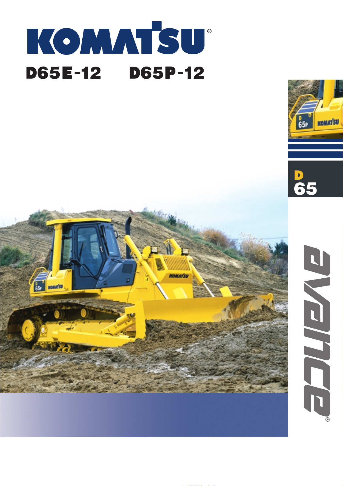
CRAWLER DOZER
Photo may include optional equipment
FLYWHEEL HORSEPOWER @ 1950 rpm
D65E-12 135 kW 180 HP
D65P-12 142 KW 190 HP
OPERATING WEIGHT:
D65E-12 19125 kg 42,160 lb
D65P-12 20185 kg 44,500 lb
WITH STEERING CLUTCH/BRAKE SYSTEM
Page 2
2
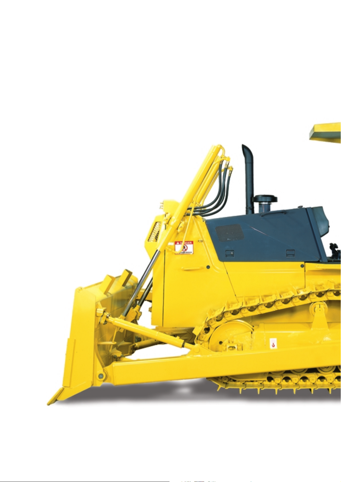
Gull-wing engine side doors
for easy and safer servicing.
The Komatsu 6D125E-2 (for D65E) and
S6D125E-2 (for D65P) diesel engine provide
an output of 135 kW 180 HP (for D65E) and 142 kW
190 HP (for D65P) with excellent productivity.
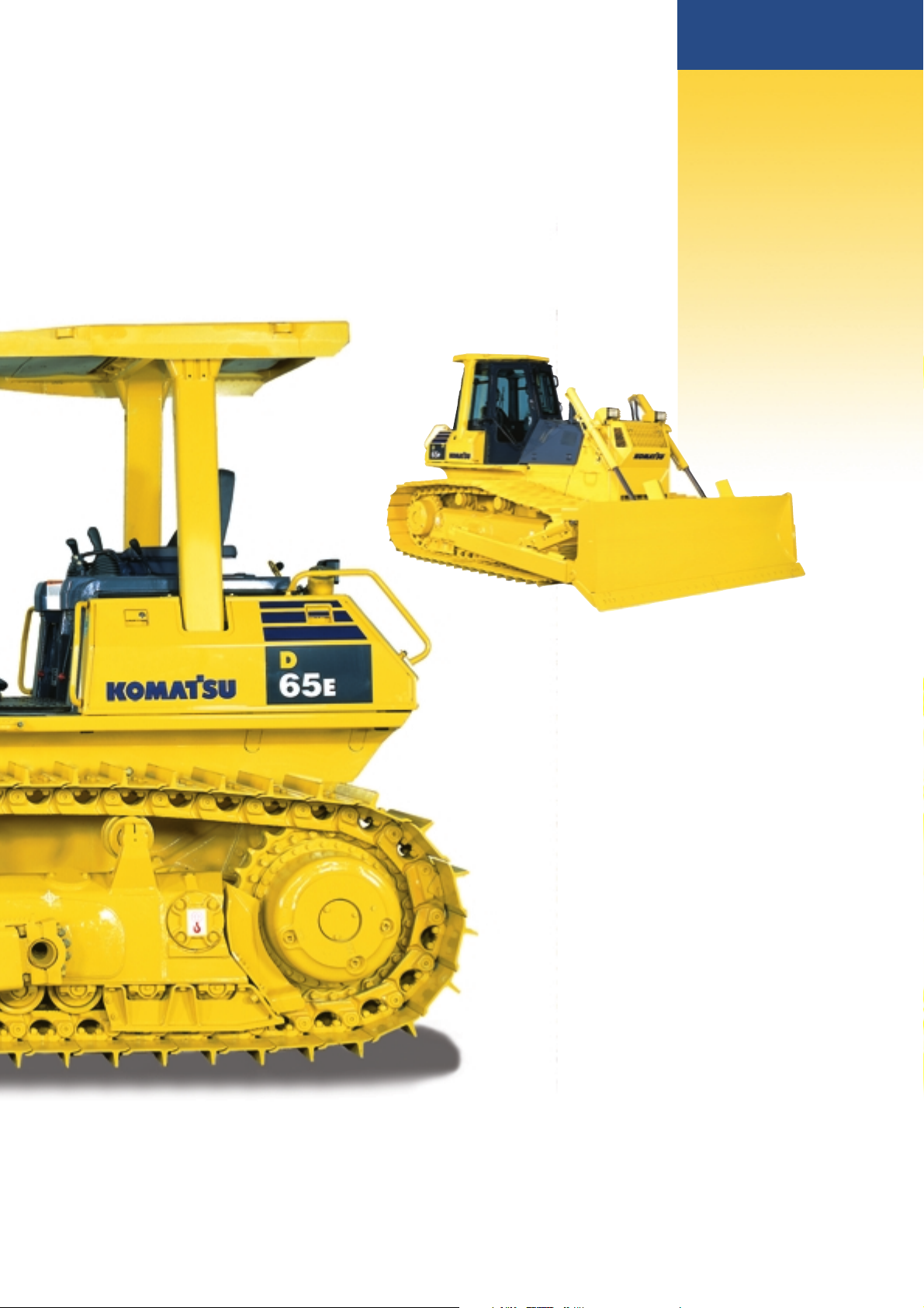
High capacity
Semi-U Tilt dozer
(for D65E), Straight Tilt dozer (for
D65P), combined the highest power in
its class with outstanding productivity.
Komatsu Torqflow transmission
offers single lever control of speed (3 forward
and 3 reverse) and directional changes.
Left hand
joystick controls all
tractor motion. Right hand joystick
controls all blade movements.
D65E-12, D65P-12 Crawler Dozer
Blade tilt lines
completely protected.
Forward mounted
pivot
shafts isolate final drives
from blade loads.
W
ALK
-A
ROUND
W
ALK
-A
ROUND
Page 3
FLYWHEEL HORSEPOWER
@ 1950 rpm
D65E-12 135 kW 180 HP
D65P-12 142 kW 190 HP
OPERATING WEIGHT
D65E-12: 19125 kg 42,160 lb
D65P-12: 20185 kg 44,500 lb
BLADE CAPACITY
Semi-U Tilt Dozer:
D65E-12: 5.61 m
3
7.34 yd
3
Straight Tilt Dozer
D65E-12: 3.89 m
3
5.09 yd
3
D65P-12: 3.69 m34.83 yd
3
D65E/P
CRAWLER DOZER
3
Electronic Monitoring System prevents
minor problems from developing into major ones.
Optional hexagonal, low noise cab
with viscous damping mounts provides unsurpassed
operator comfort and visibility.
Wet, multiple-disc brakes
eliminates brake-band adjustments
for maintenance-free operation.
Modular power train for increased
serviceability and durability.
Bolt-on segmented sprocket teeth
for easy in-the-field replacement
Photo may include optional equipment.
Page 4
Electronic Monitoring
System
An electronic monitoring
system prevents minor
problems from developing into
major ones. All meters and
gauges are controlled by a
microcomputer, which provides
a wide indication range for an easier, more
precise reading.
Low-Noise Design
For smoother riding comfort, power train components and
hydraulic control valves are mounted to the frame with
rubber pads to soften vibration and shut out noise.
Since the D65 employs joysticks, the walk-through
operator compartment is uncluttered for smooth entry
and exit. An adjustable seat with backrest is standard
equipment.
Three-stage height adjustable armrests
Three-stage height adjustable arm rests and relocated fuel
control lever provide
comfortable operation and
increased leg space.
Hexagonal Pressurized Cab (Optional)
Air filters and a higher internal air pressure combine to
prevent external dust from entering the cab. In addition, the
cab’s hexagonal design provides excellent front, side, and
rear visibility. The viscous damper cab suspension softens
shocks for operator comfort and extends component life.
Easy-to-Operate Work Equipment Control Lever
With the Closed-center Load Sensing (CLSS) hydraulic
system, blade lever stroke is directly proportional with blade
speed, regardless of the load and travel speed. This results
in superb, fine controllability.
Benefits of CLSS
● More precise and responsive operation due to the
pressure compensation valve.
● Reduced fuel consumption by discharging only the
required amount of oil from the pump.
● The work equipment moves smoothly for operations such
as side-cutting even when priority is given to steering.
4
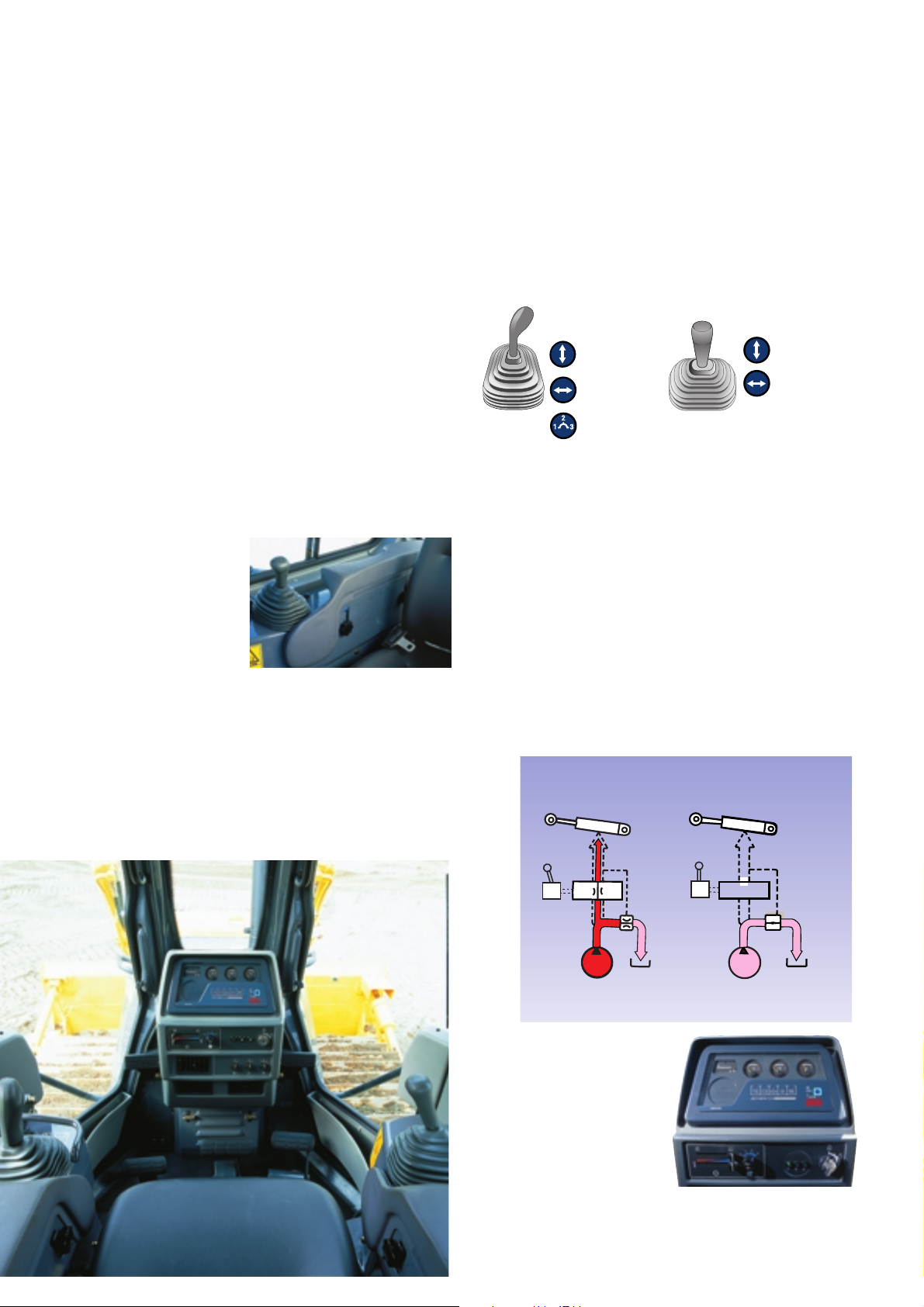
All steering, direction, and speed changes are made by a left-hand single joystick control. If the operator wants to
move the machine forward and to the left, he simply moves the joystick forward and to the left. If he desires a gear change,
he merely twists his wrist. The machine responds to the movement of the lever providing the operator with the feeling of
natural control with Komatsu’s joystick.
Cylinder
Unload
valve
Tank
Cylinder
Unload
valve
Tank
PPC
PPC
CLSS for D65E-12 and D65P-12
Steering
Functions
Forward and
reverse
Right and left
steering
First, to second,
to third shifting
Left Hand
Right Hand
Blade
Functions
Lifting and
lowering
Tilting
O
PERATOR
’
S
C
OMPARTMENT
O
PERATOR
’
S
C
OMPARTMENT
Photo may include optional equipment.
Page 5

Field-Proven Engine
Powerful S6D125E-2 (D65P) and 6D125E-2 (D65E) diesel
engines provide a massive output of 142 kW 190 HP (D65P)
and 135 kW 180HP (D65E). The engine power is
transmitted smoothly to the final drives via a high-efficiency
torque converter.
Modular Designed Power Train Units
The modular design allows easy removal and installation of
any individual unit for shorter downtime.
Flat Bottom Frame
A flat bottom frame, the monocoque track frames and
forward-mounted pivot shafts provide good maneuverability
in muddy terrain by preventing mud from building up under
the frame.
Sturdy Design
Because fewer components mean greater reliability, we’ve
designed a simple hull frame made of a thick, single plate.
Track frames have a large-section construction for maximum
rigidity. Even the box-section construction of the blade back
beam is reinforced, all with durability in mind.
D65E/P
CRAWLER DOZER
R
ELIABILITY
F
EATURES
R
ELIABILITY
F
EATURES
5
Tough Undercarriage
Large-diameter bushings, increased track link heights, and
improved oil-seals help to increase undercarriage durability.
Serviceability has also been improved with the addition of
remote greasing of the equalizer bar center pin.
Low Drive and Long Track Undercarriage
Komatsu’s design is extraordinarily tough and offers
excellent grading ability and stability.
Wet, Multiple-Disc Brakes
Eliminate brake-band adjustments for
maintenance-free operation.
Coolant Reservoir
A radiator coolant reservoir
makes it easier to check the
coolant level and eliminates
frequent refilling.
Oil Pressure Check Ports (optional)
Oil pressure check ports for the power train
are centralized on the right hand side of the
operator platform for easy access.
Gull-Wing Engine Side Covers
(optional)
A gas-spring cylinder opens the gull-wing
engine side covers widely, allowing the engine
and auxiliary components to be easily
checked.
E
ASY
M
AINTENANCE
E
ASY
M
AINTENANCE
Engine
Hull frame
Power train unit
Final drive
Pivot shaft
Track frame
Shoe
Page 6

ENGINE
Model:
D65E-12. . . . . . . . . . . . . . . . . . . . . . . . . . . . . Komatsu 6D125E-2
D65P-12 . . . . . . . . . . . . . . . . . . . . . . . . . . . Komatsu S6D125E-2
Type . . . . . . . . . . . . . . . 4-stroke cycle, water-cooled, direct injection
Aspiration:
D65E-12 . . . . . . . . . . . . . . . . . . . . . . . . . . . . . . Natural aspiration
D65P-12 . . . . . . . . . . . . . . . . . . . . . . . . . . . . . . . . . Turbocharged
Number of cylinders . . . . . . . . . . . . . . . . . . . . . . . . . . . . . . . . . . . . 6
Bore . . . . . . . . . . . . . . . . . . . . . . . . . . . . . . . . . . . . . . 125 mm 4.92"
Stroke. . . . . . . . . . . . . . . . . . . . . . . . . . . . . . . . . . . . . 150 mm 5.91"
Piston displacement. . . . . . . . . . . . . . . . . . . . . . . . . 11.04 ltr 674 in
3
Net flywheel horsepower*:
D65E-12 . . . . . . . . . . . . . . . . . . . . . 135 kW 180 HP @ 1950 rpm
D65P-12 . . . . . . . . . . . . . . . . . . . . . 142 kW 190 HP @ 1950 rpm
Net maximum torque:
D65E-12. . . . . . . . . . . . 799 N•m 81.5 kg•m 589 lb ft @ 1100 rpm
D65P-12 . . . . . . . . . . . . 981 N•m 100 kg•m 723 lb ft @ 1200 rpm
Direct injection fuel system. All-speed mechanical governor. Forced
lubrication driven by gear pump. Full-flow for lube purification.
Dry-type air cleaner with automatic dust evacuator and dust
indicator. 7.5 kW/24V electrical starter motor. 35 A/24V alternator.
140 Ah/2 x 12V batteries.
* Net flywheel horsepower output for standard engine (SAE J1349)
including air cleaner, alternator (not charging), water pump, lubricating
oil pump, fuel pump, muffler, and fan.
TORQFLOW TRANSMISSION
Komatsu’s TORQFLOW transmission consists of a water-cooled,
3-element, 1-stage, 1-phase torque converter and a planetary gear,
multiple-disc clutch transmission which is hydraulically actuated and
force-lubricated for optimum heat dissipation. Joystick control of
gears (3 forward and 3 reverse) and directional steering changes.
Gearshift lock lever and neutral safety switch prevent machine
from accidental starts.
6
FINAL DRIVE
Double-reduction final drives of spur gear and planetary gears to
minimize transmission of shocks to power train components.
Segmented sprocket are bolt-on for easy in-the-field replacement.
STEERING
Joystick controls for all directional movements. Pushing the joystick
forward results in forward machine travel, while pulling it rearward
reverses the machine. Simply tilt the joystick to the left to make a
left turn. Tilt it to the right for a right turn.
Wet, multiple-disc steering clutches are hydraulically loaded and
hydraulically released. Wet, multiple-disc brakes are spring-actuated
and hydraulically released. Steering brakes also function as service
and parking brakes.
Minimum turning radius*:
D65E-12 . . . . . . . . . . . . . . . . . . . . . . . . . . . . . . . . . . . 3.2 m 10'6"
D65P-12 . . . . . . . . . . . . . . . . . . . . . . . . . . . . . . . . . . 3.6 m 11'11"
*As measured by track marks on ground.
UNDERCARRIAGE
Suspension . . . . . . . . . . . . . . . . . . . . . Oscillation with equalizer bar
and forward mounted pivot shafts
Track roller frame. . . . . . . . . . . . . . . . . . . Monocoque, large section,
durable construction
Number of carrier rollers (each side) . . . . . . . . . . . . . . . . . . . . . . . . 2
Track shoes . . . . . . . . . . . . . . . Lubricated tracks. Unique dust seals
for preventing entry of foreign abrasives into
pin-to-bushing clearances for extended service.
Track tension is easily adjusted with a grease gun.
Travel speed Forward Reverse
1st 0–3.9 km/h 0–2.4 mph 0–5.0 km/h 0–3.1 mph
2nd 0–6.8 km/h 0–4.2 mph 0–8.6 km/h 0–5.3 mph
3rd 0–10.6 km/h 0–6.6 mph 0–13.4 km/h 0–8.3 mph
D65E-12
Number of track rollers (each side) 7
Number of shoes (each side) 39
Grouser height mm in 65 2.6"
Shoe width (standard) mm in 510 20.1"
Ground contact area cm
2
27285
in
2
4,230
Ground pressure kPa 55.9
(Tractor) kgf/cm
2
0.57
psi 8.11
Track gauge mm in 1880 6'2"
Length of track on ground mm ft.in 2675 8'9""
0
14
12
10
8
6
42
km/h
0
10
30
20
MPH
0 8642
0
40
80
120
280
160
320
200
240
0
8
16
24
56
32
64
40
48
Drawbar pull
Travel speed
lb x 10
3
kg x 10
3
kN
F1
F3
F2
D65E/P-12
Power Shift
DRAWBAR PULL VS. SPEED.
MAXIMUM USABLE PULL DEPENDS ON
TRACTION AND WEIGHT OF TRACTOR
INCLUDING MOUNTED EQUIPMENT.
D65E/P
CRAWLER DOZER
D65P-12
Number of track rollers (each side) 8
Number of shoes (each side) 45
Grouser height mm in 65 2.6"
Shoe width (standard) mm in 915 36.0"
Ground contact area cm
2
60115
in
2
9,318
Ground pressure kPa 27.5
(Tractor) kgf/cm
2
0.28
psi 3.98
Track gauge mm in 2050 6'9"
Length of track on ground mm ft.in 3285 10'9"
D65E-12
D65P-12
S
PECIFICATIONS
S
PECIFICATIONS
3
kN
lb x 10
320
64
280
56
240
48
200
40
160
32
Drawbar pull
120
24
80
16
40
8
0
0
3
kg x 10
30
20
10
0
0
0 8642
F1
2
F2
4
Travel speed
F3
10
86
14
12
km/h
MPH
Page 7

7
DIMENSIONS
G.L.
D65E-12 D65P-12
A 5440 mm 17'10" 5520 mm 18'1"
B 1880 mm 6'2" 2050 mm 6'9"
C 3165 mm 10'5" 3165 mm 10'5"
D 2990 mm 9'10" 2990 mm 9'10"
E 2675 mm 8'9" 3285 mm 10'9"
F 510 mm 20.1" 915 mm 36.0"
G 65 mm 2.6" 65 mm 2.6"
H 1270 mm 4'2" 1270 mm 4'2"
H* 1830 mm 6'0" 1830 mm 6'0"
I 1490 mm 4'11" 1490 mm 4'11"
I* 1600 mm 5'3" 1600 mm 5'3"
J 2300 mm 7'7" 2300 mm 7'7"
K 1220 mm 4'0" N/A
L 2170 mm 7'1" N/A
M 950 mm 3'1" N/A
Dimension with semi-U dozer and multi-shank ripper (D65E) and straight tilt dozer (D65P).
*ROPS canopy without cab.
COOLANT AND LUBRICANT
CAPACITY
(REFILLING)
Coolant. . . . . . . . . . . . . . . . . . . . . . . . . . . . . . . 52 ltr 13.7 U.S. gal
Fuel tank . . . . . . . . . . . . . . . . . . . . . . . . . . . . 406 ltr 107.3 U.S. gal
Engine oil . . . . . . . . . . . . . . . . . . . . . . . . . . . . . 38 ltr 10.0 U.S. gal
Damper . . . . . . . . . . . . . . . . . . . . . . . . . . . . . . 1.7 ltr 0.4 U.S. gal
Transmission, bevel gear,
and steering system . . . . . . . . . . . . . . . . . . . 48 ltr 12.7 U.S. gal
Final drive (each side)
D65E-12 . . . . . . . . . . . . . . . . . . . . . . . . . . . . 24 ltr 6.3 U.S. gal
D65P-12 . . . . . . . . . . . . . . . . . . . . . . . . . . . . 27 ltr 7.1 U.S. gal
OPERATING WEIGHT (APPROXIMATE)
Tractor weight:
Including rated capacity of lubricant, coolant, full fuel tank, operator
and standard equipment.
D65E-12 . . . . . . . . . . . . . . . . . . . . . . . . . . . . . 15620 kg 34,440 lb
D65P-12 . . . . . . . . . . . . . . . . . . . . . . . . . . . . . 16940 kg 37,350 lb
Operating weight:
Including semi U-tilt dozer (E) or straight tilt dozer (P), ROPS canopy,
steel cab, operator, standard equipment, rated capacity of lubricant,
coolant, and full fuel tank.
D65E-12 . . . . . . . . . . . . . . . . . . . . . . . . . . . . . 19125 kg 42,160 lb
D65P-12 . . . . . . . . . . . . . . . . . . . . . . . . . . . . . 20185 kg 44,500 lb
Ground clearance . . . . . . . . . . . . . . . .405 mm 1'4"
I, I*
D
G.L.
B
F
H, H*
J
E
A
G
K
C
M
M
L
FVD00585
Page 8

8
Overall Length Blade Blade Max. Lift Max. Drop Max. Tilt Additional Weight
With Dozer
Capacity*
Width x Height Above Ground Below Ground Adjustment
Hydraulic control unit
mm ft.in m3 yd3mm ft.in mm ft.in mm ft.in mm ft.in kg lb
D65E-12 5440 5.61 3460 x 1425 1105 440 465 2280 600
10.8/0.11/1.56
Semi-U Tilt Dozer 17'10" 7.34 11'4" x 4'8" 3'8" 1'5" 1'6" 5,030 1,320
D65E-12 5260 3.89 3415 x 1225 1105 440 460 2000 600
9.8/0.10/1.42
Straight Tilt Dozer 17'3" 5.09 11'2" x 4'0" 3'8" 1'5" 1'6" 4,410 1,320
D65E-12 5470 3.55 3970 x 1100 1185 450 400 2280 540
10.8/0.11/1.56
Angle Dozer 17'11" 4.64 13'0" x 3'7" 3'11" 1'6" 1'4" 5,030 1,190
D65P-12 5520 3.69 3970 x 1100 1105 540 450 2030 590
3.9/0.04/0.57
Straight Tilt Dozer 18'1" 4.83 13'0" x 3'7" 3'8" 1'9" 1'6" 4,480 1,300
DOZER EQUIPMENT
HYDRAULIC SYSTEM
Closed-center Load Sensing System (CLSS) designed for precise
and responsive control and for efficient simultaneous operation.
Hydraulic control unit:
All spool control valves externally mounted beside the hydraulic
tank.
Type of pump:
. . . . . . . . . . . . . . . . . . . . . . . . . . . . . . . . . . . . . . . . . . Gear pump
Capacity (discharge flow at rated engine rpm):
. . . . . . . . . . . . . . . . . . . . . . . . . . . . 180 ltr/min 47.6 U.S. gal/min
Relief valve setting . . . . . . . . . . . . . 20.6 MPa 210 kgf/cm22,990 psi
Hydraulic cylinders . . . . . . . . . . . . . . . . . . . . Double-acting, piston
Control valves:
Spool control valve for semi-U tilt dozer and straight tilt dozer.
Positions:
Blade lift . . . . . . . . . . . . . . . . . . . . Raise, hold, lower, and float
Blade tilt . . . . . . . . . . . . . . . . . . . . . . . . . . . Right, hold, and left
Spool control valve for angle dozer.
Positions:
Blade lift . . . . . . . . . . . . . . . . . . . . Raise, hold, lower, and float
Additional control valve for multi-shank ripper
Positions:
Ripper lift . . . . . . . . . . . . . . . . . . . . . . . . Raise, hold, and lower
Hydraulic oil capacity (refilling):
Semi-U tilt dozer. . . . . . . . . . . . . . . . . . . . . . 55.0 ltr 14.5 U.S. gal
Straight tilt dozer . . . . . . . . . . . . . . . . . . . . . 55.0 ltr 14.5 U.S. gal
Angle tilt dozer . . . . . . . . . . . . . . . . . . . . . . . 55.0 ltr 14.5 U.S. gal
Multi-shank ripper. . . . . . . . . . . . . . . . . . . . . 55.0 ltr 14.5 U.S. gal
Use of high tensile strength steel in moldboard for strengthened blade construction.
Number of cylinders Bore
Blade lift 2 95 mm 3.74"
Blade tilt 1 140 mm 5.51"
Ripper lift 1 140 mm 5.51"
Remarks:
*: Blade capacities are based on the SAE recommendation practice J1265.
STANDARD EQUIPMENT FOR BASE MACHINE
● Air cleaner, double element with
dust indicator
● Alternator, 35 ampere
● Batteries, 140 Ah/2 x 12V
● Blower cooling fan
● Decelerator pedal
● Electronic instrument monitor panel
● Engine hood
● Fenders
● Lighting system, (includes 2 front, 1 rear)
● Mono-lever steering
● Muffler with curved exhaust pipe
● Radiator guard door, flat
● Radiator reserve tank
● Rear cover
● ROPS mounting brackets
● Starting motor, 7.5 kW/24V
● Wet, multiple-disc steering clutch/brake
● Seat, adjustable
● Track roller guard, center section (P)
● Track roller guard, end sections (E)
● Track shoe assembly
—Heavy-Duty sealed and lubricated track
● 510 mm 20" single grouser
shoe (E)
● 915 mm 36.0" single grouser
shoe (P)
● Underguards, oil pan and transmission
Dozer
equipment
kg lb
Additional
Ground
Pressure
kPa kgf/cm2psi
Page 9

OPTIONAL EQUIPMENT
● Air conditioner
● AR track assembly (abrasion
resistant bushings)
● Backup alarm
● Cab
● Cab accessories
—Cup holder
—Lunch box holder
—Rear view mirror
● Cooling fan, reversible
● Engine side covers, gull-wing
● Front pull hook
● Hitch type drawbar
● Heater and defroster
● High mount foot rests
● Hydraulics for ripper (E)
● Hydraulics for tilt dozer
● Intake pipe with precleaner
● Light working, cab additional
● Locks, filler caps and covers
● Pressure check ports for power train
● Radiator core protective grid
● Rigid type drawbar
● ROPS canopy
● ROPS canopy with sweep
● Seat belt, retractable
● Suspension seat, with high-back
● Suspension seat, reclining with
fabric material (cab only)
● Track roller guard, full length
● Underguard, heavy-duty
● Vandalism protection cover
for instrument panel
● Water separator
ROPS CANOPY
● Additional weight 420 kg 930 lb
● Meets ISO 3471 and SAE J1040 APR88
ROPS standards, and ISO 3449 FOPS
standard.
● Roof dimensions:
—Length: 1830 mm 6'0"
—Width: 1600 mm 5'3"
—Height from operator compartment
floor: 1700 mm 5'7"
Additional ground pressure
D65E 1.5 kPa/0.015 kgf/cm2/0.21 psi
D65P 0.7 kPa/0.007 kgf/cm2/0.10 psi
STEEL CAB
● Additional weight 285 kg 630 lb
● All-weather, enclosed pressurized cab
● Dimensions:
—Length: 1765 mm 5'9"
—Width: 1720 mm 5'8"
—Height: 1625 mm 5'4"
—Height from floor to ceiling:
1515 mm 5'0"
Additional ground pressure
D65E 1.0 kPa/0.010 kgf/cm2/0.14 psi
D65P 0.6 kPa/0.006 kgf/cm2/0.09 psi
MULTI-SHANK RIPPER
(for D65E)
● Additional weight (including hydraulic
control unit): 1680 kg 3,700 lb
● Beam length: 2170 mm 7'1"
●
Maximum digging depth: 595 mm 1'11"
●
Maximum lift above ground: 640 mm 2'1"
Additional ground pressure
5.9 kPa/0.06 kgf/cm2/0.85 psi
ROPS CANOPY FOR CAB
● Additional weight 340 kg 750 lb
● Meets ISO 3471 and SAE J1040 APR88
ROPS standards, and ISO 3449 FOPS
standard.
● Roof dimensions:
—Length: 1270 mm 4'2"
—Width: 1490 mm 4'11"
—Height from operator compartment
floor: 1705 mm 5'7"
D65E 1.2 kPa/0.012 kgf/cm
2
/0.17 psi
D65P 0.6 kPa/0.006 kgf/cm2/0.09 psi
Models Shoe Additional weight
Ground contact Additional ground
area pressure to tractor
560 mm 22.0"
+120 kg 29960 cm
2
-3.9 kPa
single-grouser
+260 lb 4,644 in
2
-0.04 kgf/cm
2
shoe -0.57 psi
610 mm 24.0"
+230 kg 32635 cm
2
-7.8 kPa
D65E single-grouser
+510 lb 5,058 in
2
-0.08 kgf/cm
2
shoe -1.14 psi
660 mm 26.0"
+360 kg 35310 cm
2
-11.8 kPa
single-grouser
+790 lb 5,473 in
2
-0.12 kgf/cm
2
shoe -1.71 psi
950 mm 37.4"
+50 kg 62420 cm
2
-1.0 kPa
D65P circular-arc
+110 lb 9,675 in
2
-0.01 kgf/cm
2
shoe -0.14 psi
SHOES
D65E/P
CRAWLER DOZER
9
Page 10

HESS143108 Printed in Japan 200305 IP.AD (15)
www.Komatsu.com Materials and specifications are subject to change without notice
is a trademark of Komatsu Ltd. Japan
 Loading...