

Page 1
K1 - K5 - K20
TORQUE TESTER
OPERATOR’S HANDBOOK
KOLVER S.r.l - Via Corner, 19/21 - 36016 THIENE - ITALY - tel. +39 0445 371068 fax. +39 0445 371069
kolver@kolver.it - www.kolver.it
Page 2

2
1.FEATURES OVERVIEW
Controlling torque is quintessential for companies to ensure that product's quality, safety and
reliability isn't compromised. Insufficiently torqued fasteners can vibrate loose overtime and when
excessively torqued the threaded fasteners can strip. Using a quality torque tester has become
increasingly important for many companies to secure that proper torque is being applied.
The K1.K5.K20 Torque Tester is built for accuracy and reliability ever demanded for these
kinds of products. This tester accurately measures torque for most tools, meeting the
demands to test multiple torque ranges for various tools used in production. The analyser
features a built-in transducer and supports most external size transducers. Utilizing a highperformance circuitry system, the tester can store and download torque readings to a
computer at high speeds. This allows a powerful collection of analytical data to be stored for
future reference and statistical analysis of tools. Offering three modes of operation (Track,
Peak + and Peak -) this versatile analyser provides the operator a variety of ways to
smoothly verify torque applied with a selection of four measuring units. Models ranging in
torque up to 20 Nm with the built-in transducer and up to 999 Nm with the external
transducer.
Recommended for all hand screwdrivers, wrenches, or power tools.
Measuring range with built in transducer:
K1 0.05-1 Nm, K5 0.3-5 Nm, K20 0.5-20 Nm
Accuracy K1 = ± 1 cNm
K5 = ± 2 cNm
K20 = ± 3 cNm
Selection from the menu of three operation modes: (Track, Peak +, Peak -) and four units of
torque measurements: (N.m, cN.m, lbf.in, kgf.cm).
Port for external transducers.
<, =, > signals to indicate validity of torque readings with buzzer for audible user feedback.
RS-232 interface to download values stored in memory (500 values capacity).
Manual and auto reset functions to clear displayed values.
Calibration will allow for both a fast calibration (using mV/V transducers rated output) and
a true (dead weight) calibration.
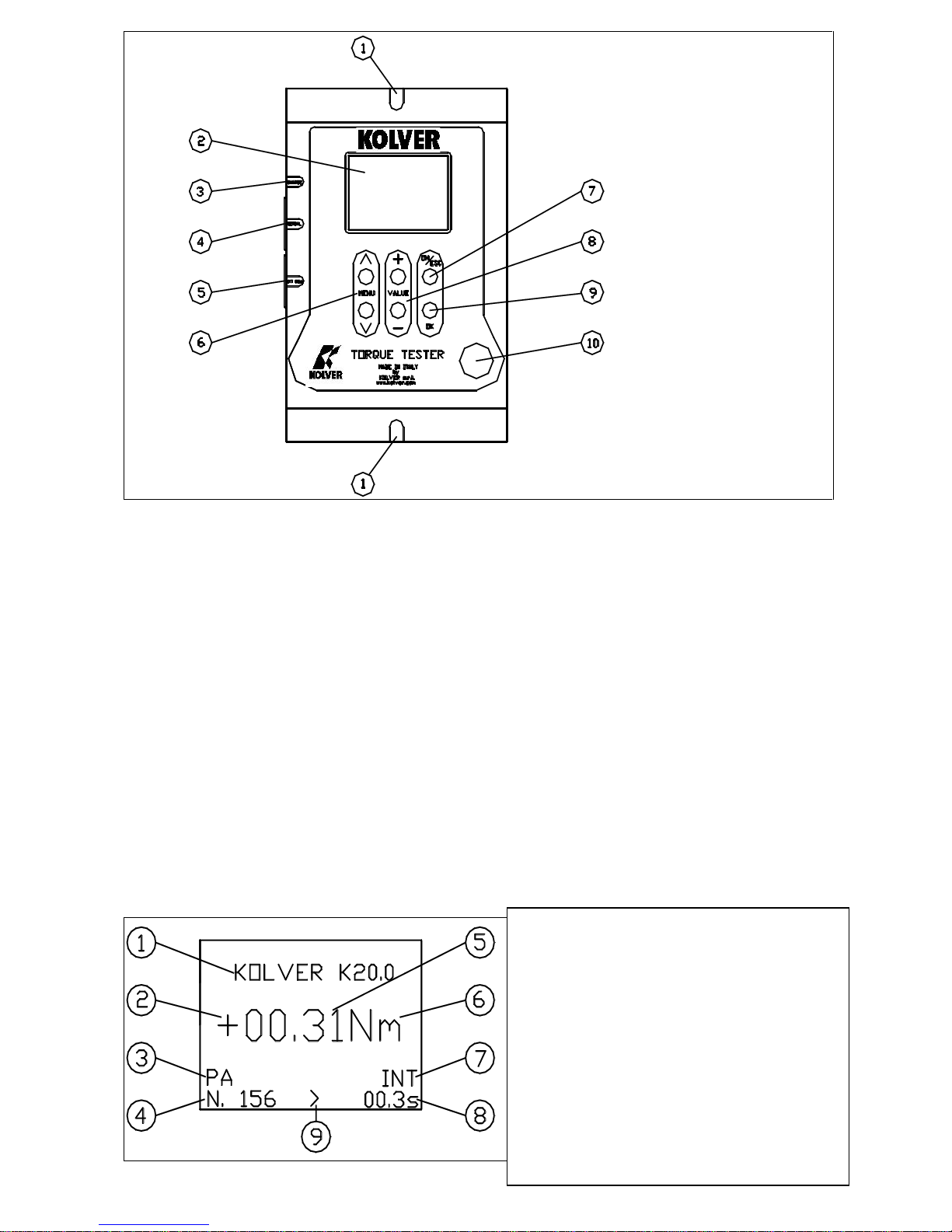
2. DESCRIPTION AND USER INTERFACE
1. Mounting holes
2. Display with 8 lines/ 16 digits
3. CHARGE: External power supply 5,5 – 2,5mm and battery charger port
4. SERIAL: RS232 output
5. EXT CELL: External transducer input and GO signal output
6. MENU keys to move through the menu. Key ^ to enter the menu.
7. Key “ON/ESC” :
Press for 3 seconds to switch the tester on or off.
Press to return to the previous screen
8. Keys: VALUE + and - to increase or decrease values when setting numbers
9. Key OK : press once
To enter a sub-menu
To save settings
To reset torque values displayed when in MANUAL clear mode
10. Internal transducer: 13mm hex male to accept the joint simulator
Page 3
3
3. MOUNTING
It is strongly recommend securing the tester through slots “1” to a workbench before operating.
Immobilizing the tester when checking torque values over 3 Nm is critical for the safety the
operator as well as for the accuracy of torque measurements during operation.
4. JOINT SIMULATOR (run down adapter)
The Joint Simulator (JS) consists of a screw compressing a series of washers (see §11). The way the
washers are mounted can simulate soft or hard joint. The screw comes with a ¼” hex male head for
proper fit to any ¼” hex female screwdriver drive. Hardened thread components increase accuracy
and life. One semi-elastic JS included. Hard joint simulator available on request.
NB. It is suggested to grease the JS each 1000 cycles.
5. STARTING AND OPERATING THE TESTER
Connect the battery charger/power supply unit.
Push the “ON/ESC” key. The display will show the main screen.
1. Model
2. “+” tightening, “-“ untightening.
3. Mode of operation: PA (peak +), PS
(peak -), Track
4. Number of measures since last reset
5. Torque value measured
6. Measuring unit
7. Transducer in use : INT or EXT
8. Time of tightening cycle
9. = GO, > < NO GO used to
monitor lower and upper torque limit
and receive a visual and audible
warning
Page 4
4
Push the ^ key to enter the menu and adjust the various settings to your requirements.
Insert the joint simulator into its 13mm hex. seat and make sure the screw is in its upper
position (if not run the driver anticlockwise to unscrew it). The tester is ready.
Run the joint simulator screw all the way down until it stops and read the torque value on
the display. Run the screw up to be ready for the next cycle.
Press the “ON/ESC” key for 3 seconds to switch the tester off. The Tester features a built-in
auto shut off mode function to save power when not in use. If there is no activity for 5
minutes, such as key press or no torque input, the tester will shut down. To restore power
press the “ON/ESC” key for 3 seconds.
In case of a deadlock, press the Reset button and restart the tester.
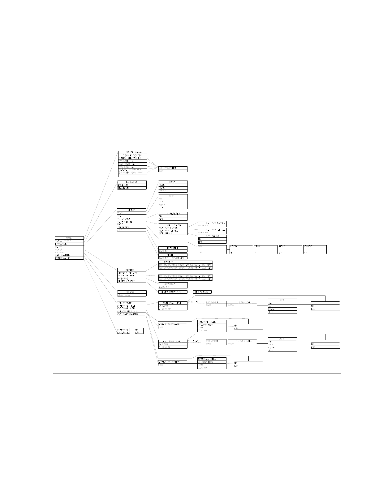
6. PROGRAM MENU
The flow chart below shows the complete menu options.
Push ^ key to enter the menu from the main screen. To move through the menus push ^ or v keys.
The indicator < on the right side of the screen will signal the selected option. Push “OK” key to
confirm the desired option.
Use + or - key to active digits when setting numbers and push OK to save them.
Protected parameters (such as calibration) need a password from Kolver or Kolver authorized
distributor.
Page 5

5
MENU OPTIONS
MODEL
This screen gives you information on the unit you are using, like serial number, software
version etc. Such data are password protected.
LANGUAGE
You can choose between English and Italian.
SETUP
The following is a quick reference for the Set-Up menu structure. If lost within the menu, you
can turn the analyser OFF and ON at any time.
MODE:
The Torque Tester offers three different mode of displaying torque information during operation.
The user will determine which mode is best suited for the application.
Key sequence to change mode:
Mode
^ o v.
OK
PEAK +
The display retains the highest torque applied clockwise.
Use this mode during calibration or testing of any power tools as well as hand type torque wrench
(dial, beam, and screwdriver).
PEAK The display retains the highest torque applied anticlockwise.
Use this mode when checking the torque needed to unscrew a tightened fastener.
TRACK
This mode constantly tracks increasing or decreasing torque variations. Use this mode to monitor
varying torque on motors and machinery. Also for calibrating and testing Dial type wrenches on a
loading bench.
MEASURING UNIT: Nm, Ncm, Kg.cm and lb.in
Key sequence to change unit:
unit
^ o v.
OK.
AUTORESET: When off push OK to remove readings from the display and reset all values to zero.
When on this process occurs automatically with any new measure.
GO - NO GO: The Torque Tester is equipped with visual (>, <, =) and audible (buzzer) signals to
provide the user instant torque status during operation. These signals operate in conjunction with
the tolerance (high limit, low limit) settings. Example: let us assume we want to calibrate our
screwdriver in the range between 0.8 and 1.0 Nm. We will then set the Low limit to 0.8 and the
High limit to 1.0. If our measure will fall inside the pre set limits the display will show =, if the
measure is below 0.8 Nm we will see <, if over 1.0 Nm we will see >. A buzzer will also signal the
measure was out of the required range. Push OK to stop the buzzer.
Note: When the values are within the pre set range an electric GO signal will be sent to pin 8 (pin 4
of 4N35) and 9 (pin 5 of 4N35) of connector EXT CELL, as per following diagram:
Page 6

6
DATE: You can set day, month, year, hour and minute.
Key sequence to change values:
date
+ or -.
OK
TRESHOLD: The parameter “threshold” indicates the minimum torque level you need to measure.
Values below this level will not be displayed. This setting enables the system to have excellent
immunity to spurious signals. Key sequence to change values:
Treshold
+ or - .
OK
ZERO: All transducers can experience some drift in the “zero” or “zero offset” point when shifting
torque from clockwise to counter clockwise or vice versa and when the transducer has not been
used for a certain time. This is a normal characteristic of transducers due to a hysteresis or lack of
“retrace”. As a result, the display may not zero and show a torque value. Key sequence to reset the
zero:
Zero
Push OK until you see 00.00
MEMORY
The memory menu will give you access to the stored values, to display and print them. You
can also see the average value of all the measure taken since you last reset the memory.
DISPLAY MEASURE: Push “OK” key and the screen will display all the data of the last measure
taken: sequence number, torque value, unit, duration of detected torque, date, hour, signals = > <
(see GO- NO GO). Push v e ^ keys to move through stored values. Push “ESC” to exit.
PRINT MEASURE: Push “OK” to send all data to the 232 serial port.
DATA DOWNLOADING
If you desire to download and display data on a computer, you can do so by using any serial
communications software. One such program is Hyperterminal accessory, standard to Windows 95,
NT, Windows 98, 2000 or XP. A description of operation is given below. This procedure may vary
slightly depending on the Windows software version being used. This is just an example, if you
have problems consult Windows Help files.
Select “Start”, “Programs”, “Accessories”, and then “Hyperterminal”. Then select
HyperTerminal.exe.
When the program starts you will be asked to choose an icon and assign a name. Choose any
icon you prefer and choose a name such as “Data_K5”, for example. Click OK.
Page 7

7
The “Connect To” screen will appear. Just click OK, or if you want to change the COM
port, select the appropriate COM port and click OK.
The “COM2 Properties” screen will appear. Choose 9600 Bits per second. Leave the default
values for character format (8 Data Bits, Parity – None, and Stop Bits 1). Change the Flow
Control to “None”. Click OK.
Click “File” on the Menu Bar and select “Properties”. When the “Data_K5 Properties”
screen appears choose the “Settings” tab and then choose “ASCII setup”. In “ASCII
receiving” check the box “Append line feeds to incoming line ends”. Click OK then OK
again.
Hyperterminal is now configured to allow torque values to be displayed on your computer screen.
If you want to capture data to a file as it is downloaded, you must enable the file capture option. To
capture to a file, select “Transfer” from the Menu Bar and select “Capture Text”. Then select the
folder and file you wish to save it as.
You can also connect the 232 serial port to a serial printer for direct data printing.
MEDIA: Push “OK” to see the average value of all the measures taken since you last reset the
memory. Please note that the program will consider the numerical values only and not the unit so
make sure all the measures have been taken under the same unit and sense of rotation.
Push “ESC” to go back to the previous screen.
RESET MEMORY: Push “OK” , the screen will display: reset memory? to ask the operator for a
further confirmation. Pushing the “OK” will delete the stored data and the screen will dispaly: no
values in memory. Push “ESC” to exit.
RS232
The Configuration of the RS 232 port is: 9600 (bits per second), 8 (data bits), n (no parity), 1 (stop
bits 1).
CALIBRATION
The torque tester comes with a calibration certificate. Further calibrations should be performed by
Kolver or authorized personnel. This menu section is password protected.
INTERNAL
This option allows the user to select the transducer to be used during operation.
Although the Torque Tester features one internal transducer, it has the unique feature to be also
used with an external transducer (optional). Key sequence to select the transducer:
OK
^ o v.
OK
The main screen will show the selected option (INT or EXT) .
7. EXTERNAL TRANSDUCER
The K tester are the unique feature to support an external rotary transducer with Wheatstone bridge
strain gauge. The tester can read rotary torque up to 20.00 Nm. External transducer for higher torque
on request. The Internal/External parameter must be set to external as outlines in section (6) for the
K tester to read the torque value from the external transducer.
PIN
FUNCTION
2
TX
Serial transmission
5
GND
0Vdc
Page 8

8
The external transducer should be connected as follows:
“EXT CELL” INPUT
PIN
DESCRIPTION
1
OUTPUT: + 2,5 V
2
INPUT: + SIGNAL FROM TRANSDUCER
3
OUTPUT: 0 V
4
INPUT: - SIGNAL FROM TRANSDUCER
8. MAINTENANCE
The K testers are maintenance free. The electronics and the internal transducer have no wearing parts.
The internal transducer should be calibrated every 12 to 30 months, depending on the frequency of
use.
WARNING: The overload protection of the internal transducer is limited to 125% of nominal value.
Damages due to overloading will result in inaccurate readings and will not be covered by our
warranty.
9. GUARANTEE
1. This KOLVER product is guaranteed against defective workmanship or materials, for a maximum
period of 12 months following the date of purchase from KOLVER, provided that its usage is limited
to single shift operation throughout that period. If the usage rate exceeds of single shift operation, the
guarantee period shall be reduced on a prorata basis.
2. If, during the guarantee period, the product appears to be defective in workmanship or materials, it
should be returned to KOLVER or its distributors, transport prepaied, together with a short
description of the alleged defect. KOLVER shall, at its sole discretion, arrange to repair or replace
free of charge such items.
3. This guarantee does not cover repair or replacement required as a consequence of products which
have been abused, misused or modified, or which have been repaired using not original KOLVER
spare parts or by not authorized service personnel.
4. KOLVER accepts no claim for labour or other expenditure made upon defective products.
5. Any direct, incidental or consequential damages whatsoever arising from any defect are expressly
excluded.
6. This guarantee replaces all other guarantees, or conditions, expressed or implied, regarding the
quality, the marketability or the fitness for any particular purpose.
7. No one, whether an agent, servant or employee of KOLVER, is authorized to add to or modify the
terms of this limited guarantee in any way. However it’s possible to extend the warranty with an
extra cost. Further information at kolver@kolver.it.
Page 9

9
10. PARTS LIST
K1
Page 10

10
REF
DESCRIPTION
CODE
1
Plastic support (4 pcs)
800016/B
2
Screw M4 x 14 (6 pcs)
240006
3
Base
240013
4
Screw M3 x 6 (2 pcs)
231504
5
Screw M3 x 22
241012
6
Screw M4 x 8 (3 pcs)
241011
7
Internal transducer 1Nm (K1)
240405
8
Washer M4 (7 pcs)
241015
9
Screw M4 x 20
241014
10
Washer ( 3 pcs)
800041
11
Screw M3 (3 pcs)
800056
12
Screw M3 x 5 (4 pcs)
240605
13
Metal housing
240001
14
PVC Washer
240017
15
Membrane
240008
16
Board and display
240002
17
Battery support (2 pcs)
800169
18
Battery 9,6V 1500mAh
240007
19
Turret M3 x 18 (4 pcs)
240016
Joint simulator M6 (K1)
240600
Case
240000
Battery charger 15V 360mA
240003/N
External transducer
ON REQUEST
Page 11

11
K5 – K20
Page 12

12
REF
DESCRIPTION
CODE
1
Plastic support (4 pcs)
800016/B
2
Screw M4 x 14 (6 pcs)
240006
3
Base
240013
4
Screw M3 x 6 (2 pcs)
231504
5
Screw M3 x 22
241012
6
Screw M4 x 8 (3 pcs)
241011
7
Internal transducer 5Nm (K5)
240503
Internal transducer 20Nm (K20)
240504
8
Washer ( 3 pcs)
800041
9
Screw M3 (3 pcs)
800056
10
Screw M3 x 5 (4 pcs)
240605
11
Metal housing
240001
12
PVC Washer
240017
13
Membrane
240008
14
Board and display
240002
15
Battery support (2 pcs)
800169
16
Battery 9,6V 1500mAh
240007
17
Turret M3 x 18 (4 pcs)
240016
Joint simulator M6 (K5)
240600
Joint simulator M8 (K20)
240800
Case
240000
Battery charger 15V 360mA
240003/N
External transducer
ON REQUEST
Page 13
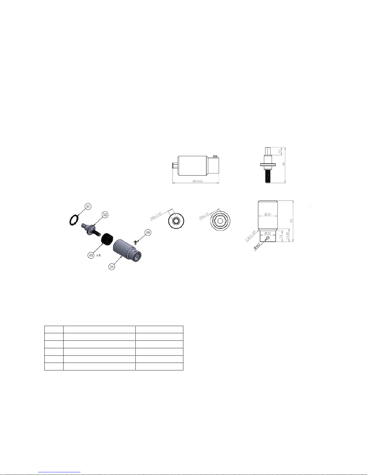
13
M6 (code 240600) – K1 & K5
Pos.
Description
Code
01
Seiger
240601
02
Joint shaft
240602
03
Washer spring (8)
240603
04
Joint housing
240604
05
Screw M3x5
872443/ZN
Page 14

14
M8 (code 240800) – K20
Pos.
Description
Code
01
Seiger
240801
02
Joint shaft
240802
03
Washer spring (12)
240803
04
Joint housing
240804
05
Screw M3x5
872443/ZN
Page 15

15
DECLARATION OF CONFORMITY
KOLVER S.r.l.
VIA MARCO CORNER, 19/21
36016 THIENE (VI) ITALIA
Declare that the new tool here described: Torque tester:
K1
020402
K5
020403
K20
020404
Is in conformity with the following standards and other normative documents: 2006/42/CE, LVD 2014/35/UE, EMCD 2014/30/UE,
EN 60745-1, EN 60204-1, EN 61000-6-1, EN 61000-6-3.
It is also in conformity with RoHS II normative (2011/65/UE).
Name: Giovanni Colasante
Position: General Manager
Person authorized to compile the technical file in Kolver
Thiene, Jan. 1st 2018 Giovanni Colasante
 Loading...