

Page 1
MANUAL
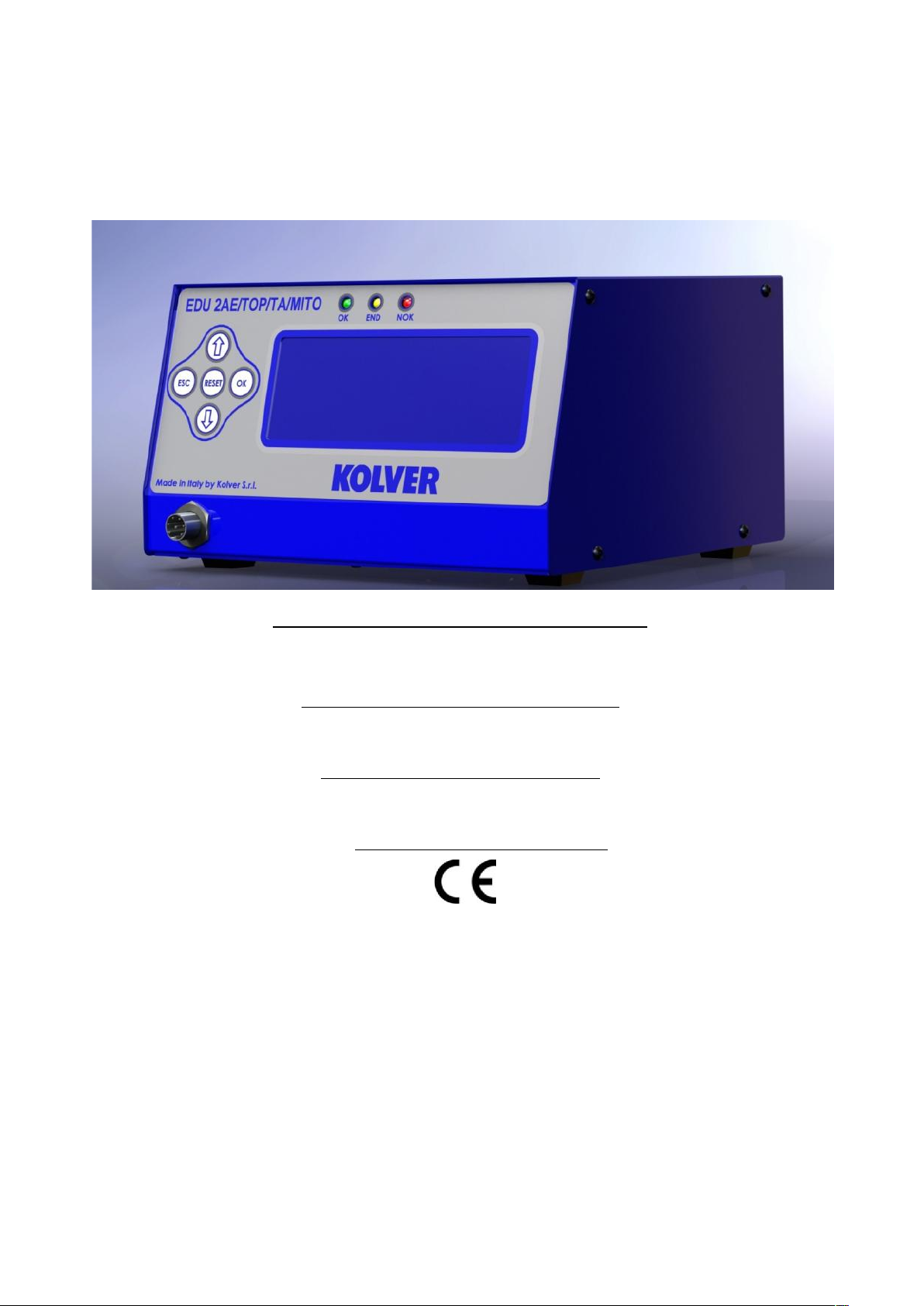
EDU 2AE/TOP/MITO and EDU 2AE/TOP/MITO/TA
Torque range: 0.05-1.5 Nm
UIDENTIFICATION DATA OF THE MANUFACTURER
KOLVER S.r.l.
VIA M. CORNER, 19/21
36016 THIENE (VI) ITALIA
UIDENTIFICATION DATA OF THE PRODUCT
CONTROL UNIT MODEL: EDU 2AE TOP/MITO
CODE: 031000/TOP/MITO - 031000/TOP/MITO/TA
TECHNICAL DATA OF THE PRODUCT
TRANSFORMER: 230V AC 50 Hz – 40 V DC 200 VA FUSE: 3,15 A
DIMENSIONS: 190 x 205 x h120 mm PESO: 4 Kg
DECLARATION OF CONFORMITY
KOLVER S.r.l. declares that the new tool here described: control unit model EDU 2AE/TOP/MITO is in
conformity with the following standards and other normative documents: 2006/42/CE, 2006/95/CE,
2004/108/CE, EN 60745-1, EN 60204-1, EN 61000-6-1, EN 61000-6-3.
It is also in conformity with the RoHS II normative.
Name: Giovanni Colasante
Position: General Manager
Person authorized to compile the technical file in Kolver
Thiene, May 2nd, 2013
Giovanni Colasante
Page 2
Manual EDU 2AE/TOP/MITO Page 2
EDU 2AE/TOP/MITO power supply and control units are an innovative system for controlling the torque of
any MITO electric screwdriver either inline, pistol, with angle head or for automation.
EDU 2AE/TOP/MITO delivers all the advantages of precision torque control electric tools at a fraction of
the price of transdurized tools.
The state-of-the-art electronic control circuit cuts the power supply to the motor calculating the correct
torque in response to 3 parameters; voltage, frequency and current, according to the selected options.
Model
Torque (Nm)
Speed
Min
Max
MITO 15H
0,05-1,5
100
850
MITO 15L
0,05-0,5
100
850
IMPORTANT: EDU 2AE/TOP/MITO is a highly accurate unit but it is critically important to select
the correct options to ensure that proper torque is being applied. Read the menu description carefully
and in case you are unsure please contact Kolver for support information.
Turn the unit on through the on/off switch on the back panel. The unit will carry a general system check and
the words “waiting connection” will appear on the last line of the display. If the connection with the motor
control board is successful the following screen will be displayed:
KolverS.R.L
.
EDU2AETOPMITO
Version1.
0
loading..
.
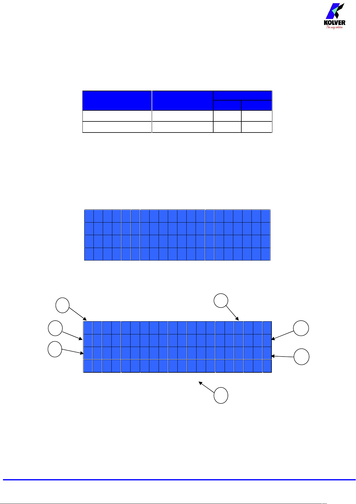
Press any key on the front panel to enter the main screen (see following picture).
MITO1510:00
PR:1S:0/0
1
T:A
:
waiting
1- Reached torque level in Nm or in.lbs
2- Program number or sequence
3- Screwdriver model
4- Clock
5- Screw count: done screws/total screws
6- Angle value in degrees (only model EDU 2AE/TOP/MITO/TA)
7- Status bar (ready, errors, etc…)
2
1
3
4
5
6
7
Page 3
Manual EDU 2AE/TOP/MITO Page 3
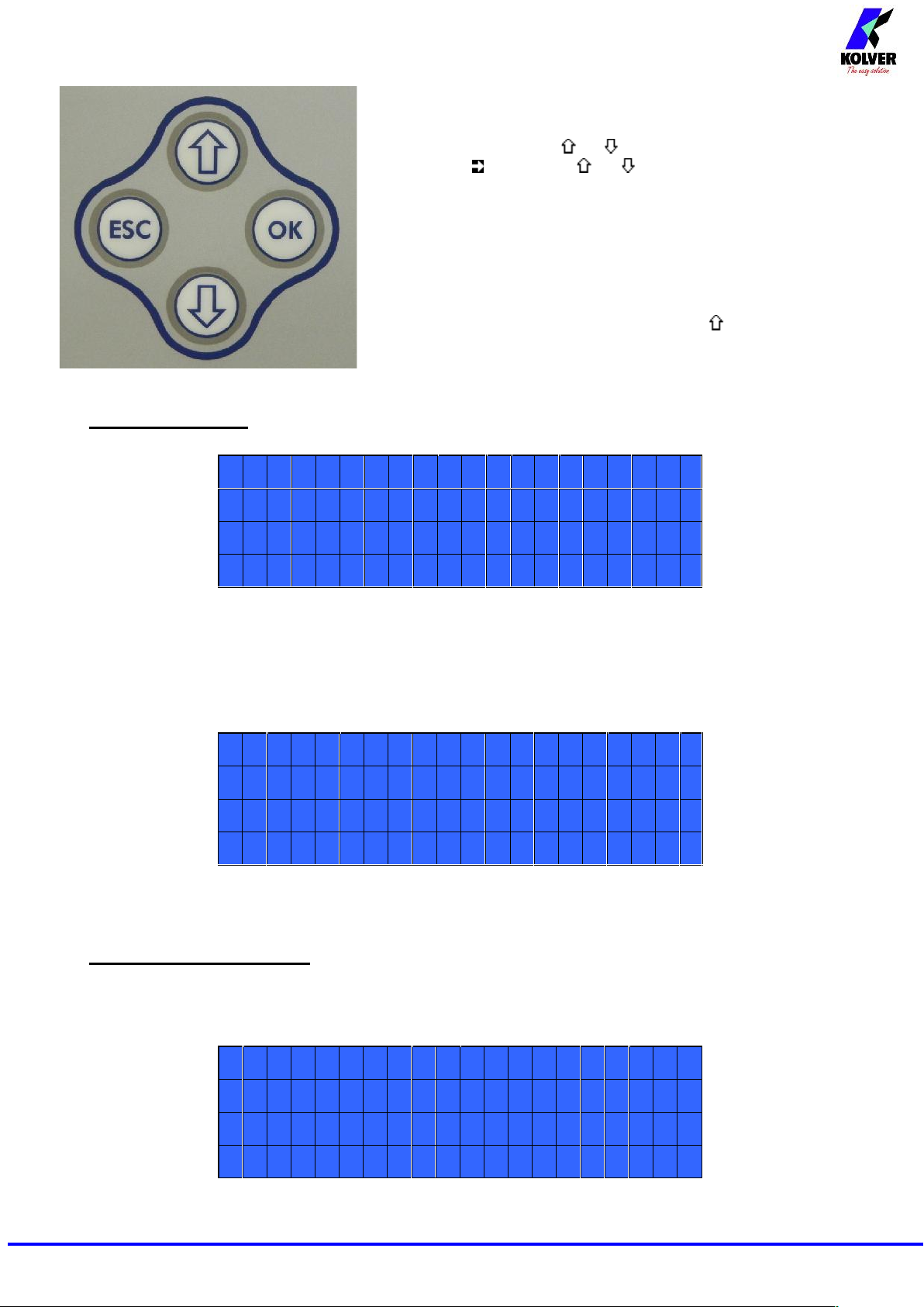
To enter the menu press the ESC key for 2 seconds.
Select the line by pressing or then press OK (the symbol
will turn into ). Press the or to select the required value
and then confirm through OK (or ESC if you don’t want to save
the value).
The selected values will be immediately operational, even if you
are still in the menu screen. Repeat the sequence for all the
parameters you wish to change and then push ESC to return to the
main screen.
Press RESET for 3 sec should you need to reset the cycle.
If you want to see all the set parameters press for 2 seconds,
however you cannot modify the displayed parameters on this
screen.
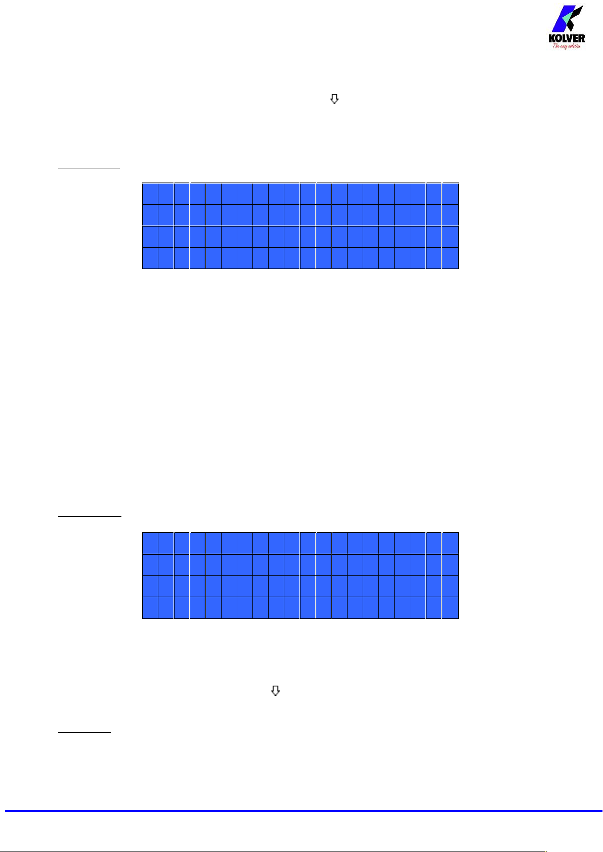
MAIN MENU:
-----MAIN-MENU-----
-
OKchangeESCquit
Programsettin
g
Sequencesetting
Program setting: It indicates the menu section where you can set or modify the fastening parameters.
To be allowed to enter this menu sequence and EXT options should be OFF.
Sequence: It indicates the menu section where you can activate the sequence, the switchbox/socket tray
and the bar code.
-----MAIN-MENU-----
-
Sequencesetting
Options
Options: It indicates the menu section where you can set date and time, the password and the language.
PROGRAM MENU:
The first 25 menu lines are available in both the EDU 2AE/TOP/MITO and EDU 2AE/TOP/MITO/TA
models. Lines from 26 to 29 are only available in the TOP/TA model.
-----MENU--PR:1----
-
OKchangeESCquit
1)Programnumber:1
2)Screwsnumber:
1
Page 4
Manual EDU 2AE/TOP/MITO Page 4
1) Program number: you can select the desired program from 1 to 8.
2) Screws number: The EDU2AE/TOP/MITO can act as screw counter. You can set the number of screws
from 1 to 99. To disable the function select OFF by pressing as many times as needed.
If the number of correct screws is equal to the number of set screws, “CYCLE END” will appear on the
status bar and the yellow led will light up. If the “Reset aut” function is disabled (see point 16), “CYCLE
END” will automatically disappear at next screwing cycle or any time you enter the menu. Otherwise, press
OK at the end of each cycle.
ATTENTION: Every time you enter the menu, the number of screws will reset.
-----MENU--PR:1----
-
3)Model:MITO1
5
4)Torque:10
%
5)Joint:SOF
T
3) Model: you can select the screwdriver to be used. Your choice will automatically change the default
settings. It’s important to select the correct model you’re going to use since most parameters regarding the
motor software are specific to every single model.
4) Torque: you can select the desired torque as a percentage of the torque range of the selected
screwdriver.The torque range is always referred to the MAX speed. In case you’re not working at maximum
speed, the torque range will progressively lower in order to avoid motor stalling. If the torque level is
reached correctly, it will be shown on the display and you will hear a beep sound, too.
Such torque level is indicated as “ T: ..% ” on the main screen.
5) Joint: You can select the type of joint you are working on. A soft joint is typically a self tapping screw
on plastic or sheet metal, or a metric (machine) screw on a material subject to strain (for example: gasket, o
ring etc.) A hard joint is typically a fastener joining metal with metal.
If you select the option SOFT the screwdriver will run the complete cycle at the selected speed (see point
6.). When selecting the option HARD the screwdriver will maintain the selected speed for a selected time
after the start (see point 4.) and then the speed will be reduced automatically to apply a pre-torque before
reaching the preset torque. The type of joint is indicated as “J” on the main screen.
IMPORTANT: An incorrect selection of the joint type can result in inaccurate torque output.
-----MENU--PR:1----
-
6)Braketime:OFF
7)Ramp:0.2s
8)Speed:600rp
m
6) Brake time: This option can be selected Uonly U in combination with the option JOINT: HARD.
It indicates how long the selected speed (higher speed) will be on before switching to “pre-torque speed”
(lower speed). The “pre-torque speed” will be automatically chosen by the unit depending on the preset
torque. You can set the brake time from 0.3 to 10.0 sec.
To disable the function select OFF by pressing as many times as needed. In this case the screwdriver will
automatically start at pre-torque speed, which cannot be set by the user.
CAUTION: The aim of the BRAKE TIME is only to speed up the approach time in case of long screws.
Reaching the torque at higher speed will result in inaccurate torque output. To avoid inaccurate torque
values we suggest selecting a shorter time, and then increase it step by step until finding the optimum time.
Torque reached during the Brake Time won’t activate the torque signal and the message “Error brake
time” will be displayed on the main screen together with 2 beep sounds. The red led will turn on, too.
Page 5
Manual EDU 2AE/TOP/MITO Page 5
7) Ramp: You can select the slow start time (acceleration) from 0.2 to 3.0 sec. This option is only available
for the screwing phase, while during the unscrewing phase the ramp time is always 0.2 sec. We suggest
using this option with self tapping screws.
ATTENTION: Reaching the torque while the ramp is still on could give as result a different torque level
from the one that results when the ramp is over. This is due to the motor acceleration.
Reaching the torque while the ramp is still on will activate the “screw OK” signal anyway (this option is
useful if you need to tighten screws that are already tightened, the so called “double hit” ).
On the other hand, if you wish to see an error signal during the preset torque in the ramp phase, you can
change the minimum time by setting value which is equal or superior to the ramp value (see point 9).
8) Speed: You can select any speed value of the screwdriver between nominal (maximum speed given in
the catalogue) and the minimum speed of every single screwdriver (see table with technical data).
-----MENU--PR:1----
-
9)Mintime:OFF
10)Maxtime:20.0
s
11)Autorev.:0.7
s
9) Min time - Minimum Time: You can set this time from 0.1 sec to 'Max time - 0.1s'. To disable the
function select OFF by pressing as many times as needed. (Min time = 0).
Torque reached below the minimum time won’t activate the torque signal and will result in an error
signal. “Below minimum time” will be displayed on the status bar and the red led will light up. You will
hear two beep sounds, too.
10) Max time - Maximum time: You can select the maximum time of tightening. You can set from 'Min
time + 0,1s' to 20.0 sec.
ATTENTION: If torque isn’t reached by the maximum time, the screwdriver will stop. “Over maximum
time” will be displayed on the status bar and the red led will light up. You will hear two beep sounds, too.
11) Auto rev. – Auto reverse: This option will automatically start a reverse cycle after a torque reached
signal. You can set time from 0.1 to 20.0 sec.
To disable the function select OFF by pressing as many times as needed.
ATTENTION: During the reverse cycle, it is necessary to keep the lever or the start signal pressed as long
as it won’t stop. “Correct screw” will be displayed on the status bar and a green led will light up. You will
hear one beep sound, too. In case the lever is released before the end of the reverse cycle, “unfinished
screw” will be displayed and a red led will light up. You will hear two beep sounds, too.
-----MENU--PR:1----
-
12)Revspd:600rp
m
13)Revtorque:MA
X
14)PVtorque:OFF
12) Rev spd - Reverse speed: You can select any reverse speed value of the screwdriver between the
maximum and the minimum specific speed of every single screwdriver (see table with technical data).
13) Rev torque – Unscrewing torque: You can select the desired torque as a percentage of the torque
range of the selected screwdriver (see point 3). If the torque is set on MAX, the unscrewing torque is about
20% higher than the possible maximum torque, so that it is always possible to unscrew the tightened screw
(we suggest leaving this function on in normal use). If the setting is from MIN to 99% the unscrewing
torque with the same percentage will be equal to the settings of the screwing phase.
Page 6

Manual EDU 2AE/TOP/MITO Page 6
ATTENTION: If you’re using open-end wrenches, the unscrewing torque has to be set to MIN value in
order to bring the wrench back to the correct position.
14) PV torque: Period of time in which the screwdriver works at maximum torque before switching to
the torque that has been set by the user. You can set time from 0.1 to 10.0 sec. To disable the function select
OFF by pressing as many times as needed.
This function overlaps other time settings (brake time, ramp time, minimum time, maximum time) from the
motor start on.
ATTENTION: This function is useful for applications where the prevailing torque is higher than the final
torque (for example trilobal screws or locknuts).
Please use this function with utmost attention because an incorrect use can damage both the assembly
and the screwdriver.
Torques reached during the max torque time won’t activate the torque signal. “Error pvt time” will be
displayed and the red led will light up. You will hear two beep sounds, too.
-----MENU--PR:1----
-
15)Rotation:right
16)Resetaut:O
N
17)PressESC:OFF
15) Rotation: You can choose between right tightening (standard screws) or left tightening (left threaded
screws). All the other functions will adapt to the selected direction of rotation.
16) Reset aut : If ON, the control unit resets automatically after a cycle end.
If OFF, press OK every cycle end.
17) Press ESC: If ON, the control unit will after an error signal, then press ESCto reset.
If OFF, the control unit resets automatically.
-----MENU--PR:1----
-
18)Errorlever:O
N
19)Defixallow:OFF
20)Calibration:ON
18) Error lever: If ON, an error signal will occur if the lever has released before reaching the torque.
If OFF, this function doesn’t work.
19) Defix allow: if ON, the reverse switch on the screwdriver will work normally. If OFF, if you want the
screwdriver will work only forward.
20) Calibration: If ON, you will see the torque value (Nm or in.lbs) on the main screen.
If OFF, the torque value won’t be displayed.
(To modify the calibration parameters see paragraph Torque calibration).
-----MENU--PR:1----
-
21)Compens:+0.00N
m
22)Unit:N
m
23)Torqmin:0.00Nm
Page 7
Manual EDU 2AE/TOP/MITO Page 7
21) Compens – Compensation: This function allows an increase or decrease of the displayed torque
after calibration. The available range is from 0 to ±9.99 Nm. For example: after calibration (see Torque
calibration) you make a screwing cycle on your assembly and compare the value you see on the main screen
display with the value you see on a torque tester (for example a mini-K or a K model). Let's say you notice
that the torque displayed in the unit EDU 2AE/TOP/MITO is +0.2 Nm higher than the value indicated on
the tester (which is the right one). In this case you change this value by setting -0.2 Nm so that the value on
the screen will be the same as the value on the tester. If it’s lower than 0.3 Nm, you need to set +0.3 Nm and
so on.
22) Unit: You can choose between the following units of measurements: Nm and in.lbs.
23) Torq min – Minimum torque: The minimum torque and maximum torque options allow the user to
set the acceptable torque range for each single application. When the reached torque is inside this range,
“tightening OK” will be displayed on the status bar and the green led will light up. If the reached torque is
outside this range the messages “error minimum torque” or “error maximum torque” will be displayed. You
can set the torque range from 0 to 40 Nm in steps of 0.01 Nm.
The minimum torque option allows to set the lowest value of the torque range and it’s on if calibration is
ON. If calibration is OFF, the minimum torque value automatically sets on 0 Nm.
-----MENU--PR:1----
-
24)Torqmax:1.50Nm
25)Ins.barcod
e
26)FuncT&A:OF
F
24) Torq max – Maximum Torque: The minimum torque and maximum torque options allow the user
to set the acceptable torque range for the single application. When the reached torque is inside this range,
“right screwing” will be displayed on the status bar and the green led will light up. The messages “below
minimum torque” or “over maximum torque” will be displayed if the reached torque is outside this range.
You can set the torque range from 0 to 40 Nm at intervals of 0.01 Nm.
The maximum torque option allows to set the highest value of the torque range and it’s on if the calibration
is ON. If the calibration is OFF the maximum torque value automatically sets on 40 Nm.
25) Ins. barcode: to scan a barcode and recall the desired program. To be used in combination with option
4. of the Sequence Menu.
THE FOLLOWING MENU IS AVAILABLE ON TA VERSION ONLY
26) Func T&A–T&A function mode: You can activate the Torque & Angle function. Set OFF if you
don’t need this function. If you set ON you can choose among six working conditions (see T&A specific
instructions).
-----MENU--PR:1----
-
27)StartingTor:--
-
28)Ang.min:--
-
29)Ang.max:--
-
27) Starting Tor – Starting torque: If T&A option is set on Tor mode (See T&A paragraph), you can
set the torque threshold the angle starts to be read from. If T&A is set on angle mode (see T&A paragraph),
you can set the torque threshold the angle starts to be carried out from.
Page 8
Manual EDU 2AE/TOP/MITO Page 8
28) Ang. min – Minimum angle: Minimum angle threshold. You can set it if T&A is set on Tor, T/in or
T/lv (see T&A specific instructions). The minimum angle the operator can set is 5°.
29)Ang. max - Maximum angle: Maximum angle threshold. You can set it if T&A is set on Tor, T/in or
T/lv (see T&A specific instructions). The maximum angle the operator can set is 9720°.
If T&A is set on Ang., A/in or A/lv mode, maximum angle corresponds to the angle that has to be carried
out.
SEQUENCE MENU:
---SEQUENCE-MENU---
-
OKchangeESCquiT
1)Seqset:14739812
2)Sequence:OF
F
1) Seq set: you can set a sequence up to max. 8 programs. To set the next program in the sequence, press
OK.
2) Sequence: It allows to enable or disable the sequence. ON = enabled; OFF = disabled.
---SEQUENCE-MENU---
-
3)Extbox:OF
F
4)Mod.barc:OF
F
5)Res.autseq:OF
F
3) Ext box: It allows to enable or disable the external switch box. ON = switch box enabled; OFF = switch
box disabled.
4) Barc. mode: – Barcode mode: It allows to choose the barcode mode.
OFF: barcode disabled.
ON prog: you can select the program to be executed by scanning the bar code of the product. The
unit compares the scanned code to the one previously entered in each program (see point 25: Barc.
Set.). If the two codes are the same as the program is loaded, otherwise it will appear Error
Barcode. The scanned product code is also printed on the serial port of the control unit (see
paragraph “serial print”).
ON S.N.: the product code is required before carrying out a cycle or a sequence. The product code
is printed on the serial port of the control unit.
5) Aut. res seq: If ON, the control unit automatically resets after the end of the sequence. If OFF it is
necessary to press OK at the end of each sequence.
OPTION MENU:
----OPTION--MENU---
-
OKchangeESCquit
1)Language:IT
2)Changepasswor
d
Page 9

Manual EDU 2AE/TOP/MITO Page 9
1) Language: This option allows to choose among 6 languages: English, Italian, German, Spanish, French
and Portuguese.
2) Change password: You can change password (see point 3).
----OPTION--MENU---
-
3)Password:ON
4)ESC-OK:INT+EX
T
5)Reset:PRG
3) Pass ON: If YES, you will be asked for the password to enter the menu. Otherwise select NO.
ATTENTION: Password is only asked to enter the menu the first time after switching the unit on.
The default password is: 0000.
4) ESC-OK: Press ESC in case of error. Press OK at cycle end or to reset a cycle or a program (see point
5: Reset). If INT, the operator must press the required key on the front panel. If it’s set on EXT, the keys on
the front panel are disabled and functions can only be enabled through proper connections on the back panel
(see paragraph “I/O connections”).
5) Reset: you can select which parameter resets when you press RESET (see point 4: Keyboard
commands). If PRG, the Reset refers to the program that is being carried out. If SEQ, the Reset refers to the
whole sequence (only if sequence is enabled).
----OPTIONS-MENU---
-
5)Reset:PRG
6)Settime&dat
e
7)Cycles:000000
0
6) Set time & date: to set time and date on the control unit.
7) Cycles - Total number of cycles: It shows the number of tightened and loosened screws. This number
can’t be modified.
TORQUE CALIBRATION
Please read the instructions carefully and equip a torque tester to proceed.
The torque calibration function allows to view the torque value in Nm or in.lbs directly on the display.
ATTENTION: The displayed torque level is approximate and it’s determined by mathematical calculations.
The smaller the calibration interval the more precise the value on the screen.
IMPORTANT WARNINGS:
Calibration values will be referred to the parameters of the control unit which are set during
calibration. If you modify speed or type of joint, the unit will need to be recalibrated.
If the screwing cycle during calibration isn’t carried out correctly or if you’re not sure of the value
it’s possible to repeat it. A wrong screwing cycle can affect the precision of the calibration cycle.
Calibration is carried out for two torque levels optionally chosen. The minimum calibration interval
is 5% (example: if I have to work at 30%, I can calibrate at 25% and 35%) but we recommend a
minimum of 10% interval.
Page 10

Manual EDU 2AE/TOP/MITO Page 10
Torque percentages which are higher than the maximum one set during the calibration will be
analyzed and displayed anyway. They will be theorized by the system and they won’t be based on
effective data, therefore the analysis won’t be precise.
During the calibration it’s impossible to go back to the previous screen. Press ESC to stop
calibration and then repeat the cycle.
CALIBRATION PROCESS:
1. Select Calibration at point 17 of the menu and press OK.
2. The following screen will appear on the display:
--------MENU-------
-
20)CalibrationO
N
3. Choose if you want to set calibration ON or OFF, then press OK to confirm or ESC to exit. If you
choose OFF calibration will be interrupted and no torque value will be displayed. If you choose ON
calibration will continue and the following screen will be displayed:
4. Set the first torque level percentage by pressing o , then press OK.
5. Complete a fastening cycle.
6. If you’re sure of the torque level displayed on your torque tester press OK, then set the displayed
value and press OK again to save. Otherwise press ESC and start again.
7. The following screen will be displayed. Set the percentage of the second torque by pressing or
and press OK.
8. Repeat the procedures described on points 4 and 5.
9. When calibration ends, “Setting end” will be displayed. You will hear two beep sounds, too.
ATTENTION: If you press ESC after confirming “calibration ON”, the display will show the torque screen
again and the displayed values are the default ones or the ones set during the previous calibration (if done
before).
--------STEP--1----
-
Insertthe
percentageMIN
--------STEP--2----
-
Insertthe
percentage02%
Page 11

Manual EDU 2AE/TOP/MITO Page 11
USE OF T&A (Torque & Angle)
Choose the T & A mode (see point 26: Modify function on the program menu)
It is possible to set 6 different modes:
TORQUE (Torque): It’s the most common use mode. The control unit shows the tightening torque and
the torque starting from a certain torque percentage (threshold torque, see point 27). If the final torque
and angle values are within the preset minimum and maximum values, the screw is correctly tightened.
If the torque and/or angle are outside the preset values, the screw will be considered as incorrectly
tightened. In this case the red led will light up and the message “Error Max (Min) Angle” or “Error Max
(Min) Torque” will be displayed.
TORQUE/INPUT (T/IN): It corresponds to Torque mode, except for the threshold torque which
can’t be set by the operator: in fact the value is the result of an external impulse through a proper
contact (see paragraph “connections”). It can be very useful if the operator wants the control unit to
start counting the angle from a position which is indicated by a precision instrument.
TORQUE/LEVER (T/LV): No threshold is preset by the operator: the angle value that appears on
the display corresponds to the angle that is carried out starting from the moment in which the lever
is pressed until the torque is reached.
Page 12

Manual EDU 2AE/TOP/MITO Page 12
ANGLE (Ang.): This mode gives priority to the angle to be reached. The value is measured starting
from a tightening torque percentage.
Starting from the preset threshold torque (see point 27) the system will start counting the degrees
and when the preset angle is reached the screwdriver will stop. If the preset angle is reached the
screw will be considered as correctly tightened, the green led will light up and the message
“tightening OK” will be displayed on the status bar. If the screwdriver stops before reaching the
preset angle the tightening will be considered not ok, the red led will light up and the message “error
angle not reached” will be displayed on the status bar. Therefore it’s very important to set a torque
value (line 4) which is sufficiently higher than the threshold value (line 27), so that the set value is
reached before the screwdriver stops because of the reached torque.
ANGLE/INPUT (A/IN): The threshold can’t be set by the operator: in fact the value is the result of
an external impulse through a proper contact (see paragraph “connections”).
This function can be very useful if the operator wants the screw to rotate a certain number of
degrees after reaching a position indicated by a precision instrument.
ANGLE/LEVER (A/LV): the threshold torque value can’t be set by the operator and the angle value
that appears on the display corresponds to the angle that is carried out starting from the moment in
which the lever is pressed
Page 13

Manual EDU 2AE/TOP/MITO Page 13
INTERPRETATION OF ACOUSTIC SIGNALS
The control unit emits sounds which help you understand if the fastening operation has been carried out
correctly or incorrectly. When the torque is reached meeting all the parameters set, the control unit utters a
0.5 sec beep as confirmation. On the other hand, torque reached under min time, during the Ramp time or
under the Brake time (see error signals on the display) will cause the control unit to utter two beep sounds.
In case of wrong settings (e.g. both sequence and switchbox are enabled or the selected switch box program
is different from the one required by the sequence) the control unit will utter a long beep sound.
I/O CONNECTIONS:
Page 14

Manual EDU 2AE/TOP/MITO Page 14
CN1 CONNECTOR – 10 pins:
It is situated on the upper part of the back panel.
PIN
NOME
FUNZIONE
OUTPUT
1
NOT
USED
2
COM
0VDC
Common pin. Signals must be taken between this pin and the respective signal pins (pin 3, 4
and 5).
3
ERROR
Error signal: it activates every time an error occurs.
The error signal resets after 3 beep sounds.
Signal is 24VDC.
4
LEVER
Lever signal: when lever is pressed or when the start is remote. No signal during unscrewing
cycle. It resets after their release. Signal is 24VDC.
5
TORQUE
Torque signal. It activates every time the torque is reached and it resets when the lever or
remote start is released. Signal is 24VDC
INPUT
6
T&A
INPUT
External input for making the control unit start to count the angle. It can be only used in
A/IN and T/IN mode (see T&A paragraph)
7
STOP
MOTOR
Remote motor stop. If it’s activated the message “STOP MOTOR ON” appears on the
display. The motor will stop and won’t start working again as long as the contact is closed
8
REVERSE
Remote motor start with torque control while unscrewing.
9
START
Remote start with torque control while screwing.
10
COM
0VDC
Common pin. The desired function is activated through a contact between this pin and one
of the other pins (pin 6, 7, 8, 9). This pin is connected to 0VDC and to the ground.
Page 15

Manual EDU 2AE/TOP/MITO Page 15
CN2 CONNECTOR – 14 pins:
All of the following pins are input: make a contact with pin 14 to activate them.
PIN
NAME
FUNCTION
1
NOT USED
2
MISSING PIECE
If enabled it stops the motor, enables the error signal and “Error missing
piece” is displayed on the status bar
3
OK EXT
If enabled (see point 4: OK-ESC commands, in the option menu), remote
OK key function.
4
ESC EXT
If enabled (see point 4: OK-ESC, in the option menu), ESC key function to
reser remote errors.
5
RESET EXT
If enabled (see point 4: OK-ESC commands, in the option menu), it resets
program or sequence according to the preset function (see point 5: Reset , in
the option menu)
6
INPUT 8
Switch – selection of program 8
7
INPUT 7
Switch – selection of program 7
8
INPUT 6
Switch – selection of program 6
9
INPUT 5
Switch – selection of program 5
10
INPUT 4
Switch – selection of program 4
11
INPUT 3
Switch – selection of program 3
12
INPUT 2
Switch – selection of program 2
13
INPUT 1
Switch – selection of program 1
14
COM0VDC
Common to every input (1-13). Signals have to be enabled making contact
between the desired signal and this pin (common 0VDC) .
Page 16

Manual EDU 2AE/TOP/MITO Page 16
CN3 CONNECTOR – 11 pins:
All of the following pins are output.
PIN
NAME
FUNCTION
1
GREEN LED
This signal works in parallel with the green led on the front panel.
2
RED LED
This signal works in parallel with the red led on the front panel.
3
YELLOW LED
This signal works in parallel with the yellow led on the front panel.
4
SEQUENCE END
It indicates the end of a sequence, if enabled.
5
NOK T&A
It activates if any angle error occurs.
6
PR OK
It activates at the end of each program.
7
MOTOR ON (\W)
It activates when the motor runs while tightening.
8
STOP MOTOR
It activates when stop motor is enabled.
9
NOT USED
10
NOT USED
11
COM0VDC
Common to every output. Signals have to be enabled making contact
between the desired signal and this pin (common 0VDC) .
Page 17

Manual EDU 2AE/TOP/MITO Page 17
CN4 CONNECTOR – 9 pins:
All of the following pins are output.
PIN
NAME
FUNCTION
1
OUTPUT 1
It indicates you’re using program 1
2
OUTPUT 2
It indicates you’re using program 2
3
OUTPUT 3
It indicates you’re using program 3
4
OUTPUT 4
It indicates you’re using program 4
5
OUTPUT 5
It indicates you’re using program 5
6
OUTPUT 6
It indicates you’re using program 6
7
OUTPUT 7
It indicates you’re using program 7
8
OUTPUT 8
It indicates you’re using program 8
9
COM0VDC
Common to every output. Signals have to be enabled making contact
between the desired signal and this pin (common 0VDC) .
Page 18

Manual EDU 2AE/TOP/MITO Page 18
CN5 CONNECTOR (25 pin connector - female):
PIN
NAME
FUNCTION
1
COM 0VDC
Common to every input. Signals have to be enabled making contact between
the desired signal and this pin (common 0VDC) .
2
Not used
3
STOP MOTOR
It indicates stop motor is enabled
4
OUTPUT 8
It indicates you’re using program 8
5
OUTPUT 7
It indicates you’re using program 7
6
OUTPUT 6
It indicates you’re using program 6
7
OUTPUT 5
It indicates you’re using program 5
8
OUTPUT 4
It indicates you’re using program 4
9
OUTPUT 3
It indicates you’re using program 3
10
OUTPUT 2
It indicates you’re using program 2
11
OUTPUT 1
It indicates you’re using program 1
12
+24VPLC
+24VPLC available on this pin, they can’t be used to charge external devices.
13
+5VDC
+5VDC available on this pin, it can’t be used to charge external devices
14
OK EXT
If enabled (see point 4: OK-ESC, in the option menu), remote OK key
function.
15
ESC EXT
If enabled (see point 4: OK-ESC, in the option menu), ESC key function to
reset remote errors.
16
RESET EXT
If enabled (see point 4: OK-ESC, in the option menu), it resets program or
sequence according to the preset function (see point 5: Reset, in the option
menu)
17
INPUT 8
Switch – selection of program 8
18
INPUT 7
Switch – selection of program 7
19
INPUT 6
Switch – selection of program 6
20
INPUT 5
Switch – selection of program 5
21
INPUT 4
Switch – selection of program 4
22
INPUT 3
Switch – selection of program 3
23
INPUT 2
Switch – selection of program 2
24
INPUT 1
Switch – selection of program 1
25
COM +15VCC
+15VCC available on this pin, not used to charge external devices
CN6 CONNECTOR (serial connector 9 pin - male) - FOR BARCODE CONNECTION
PIN
NAME
FUNCTION
1
COM +15VCC
+15VCC available on this pin, it can’t be used to charge external devices.
2
RX
Serial reception.
3
TX
Serial transmission.
5
COM 0VDC
Common to every input. Signals have to be enabled making contact between
the desired signal and this pin (common 0VDC).
9
COM +5VDC
+5VDC available on this pin, it can’t be used to charge external devices.
Page 19

Manual EDU 2AE/TOP/MITO Page 19
CN7 CONNECTOR (9 pin serial connector - female) – PRINT FUNCTION
PIN
NAME
FUNCTION
1
COM +15VCC
+15VCC available on this pin, it can’t be used to charge external devices.
2TXSerial transmission.
5
COM 0VDC
Common to every input. Signals have to be enabled making contact between
the desired signal and this pin (common 0VDC).
9
COM +5VDC
+15VDC available on this pin, it can’t be used to charge external devices.
USB-PRINT CONNECTOR
Only used to print data on PC (see dedicated paragraph).
ATTENTION: Output signals are protected from an appropriate circuit. Overload of the available
signals (> 400 mA) or short circuit will result in the stop of the unit. To re-activate signals, it is
necessary to switch off the unit for 5-6 seconds, check connections and output loads then switch the
unit on.
TROUBLE SHOOTING
ERROR
PROBLEM
SOLUTION
0
“waiting connection” doesn’t turn into “system
ready” after it’s been switched on.
Check flat connector inside the unit
1
“tightened screw” is displayed on the status bar (the
torque signal is displayed during the motor startup
process which lasted 0.3sec).
Check parameters once again
2
“Error brake time” is displayed on the status bar
(the torque signal is displayed during the brake
time).
3
“reverse incomplete” is displayed on the status bar
(the displayed torque signal is correct but the set
unscrewing is not complete).
4
“Below min time” is displayed on the status bar (the
torque signal is displayed below the set minimum
time).
5
“Over maximum time” is displayed on the status bar
(torque is not reached because the tightening time is
over the preset maximum time).
6
“Error PV torque” is displayed on the status bar
(the torque signal is displayed before the preset PV
torque is reached).
7
“Below min torque” is displayed on the status bar
(the torque signal is displayed below the preset
minimum torque).
Page 20

Manual EDU 2AE/TOP/MITO Page 20
8
“Over max torque” is displayed on the status bar
(the torque signal is displayed over the set maximum
torque).
Check parameters once again
9
“Below min angle” is displayed on the status bar
(the torque signal is displayed below the set
minimum angle).
10
“Error max angle” is displayed on the status bar
(The max preset angle has been reached. Only
available in Tor, T/lv and T/in mode).
11
“Error angle not OK” is displayed on the status bar
(The preset angle hasn’t been reached. Only
available in Ang., A/lv andA/in mode).
12
“Error missing piece” is displayed on the status bar
(The “missing piece” contact is enabled).
-check contact 2 on the CN2 connector
13
“Compensation error” is displayed on the status bar.
A negative torque value is displayed due to a high
negative compensation value.
- increase or decrease the compensation value
14
“Transmission error” is displayed on the status bar
(The data transmission from display board to motor
board is incorrect).
-press ESC to retransmit data
-if this error persists, restart the control unit
15
“Released lever error” is displayed on the status bar
(The lever has been released while tightening).
Such error can be enabled or disabled
through “PROGRAM-MENU” (see point 18
on the program menu).
16
“Error loosen torque” is displayed on the status
bar (The torque signal is displayed while
loosening, but only if it’s set on “max”).
- The screwdriver couldn’t loosen
- Avoid motor stalling
- Loosening too heavy
17
“Output Disabled”. Protection of output signals was
activated after exceeding maximum load (400mA).
- Check the set load is not over the allowed
maximum value
- Restart the control unit to reset error
18
“Protection 4A” is displayed on the status bar (it
happens when current on mosfets of bridge H is >
12 A for at least 1 s)
- Decrease cycle time and check settings
- Avoid motor stalling
- Unscrewing too heavy
- Joint too soft
19
“Protection 4p5A” is displayed on the status bar (it
happens when current on mosfets of bridge H is >
14.5 A for at least 800 ms)
- Decrease cycle time and check settings
- Avoid motor stalling
- Unscrewing too heavy
- Joint too soft
20
“Protection 5A” is displayed on the status bar (it
happens when current on mosfets of bridge H is > 15
A for at least 500 ms)
- Decrease cycle time and check settings
- Avoid motor stalling
- Unscrewing too heavy
21
“Calibration error” is displayed on the status bar
-check the Calibration and do it again
Manual EDU 2AE/TOP/MITO Page 21
Page 21

ATTENTION: IF THE OK/ESC OPTION IS DISABLED, ERRORS RESET AT THE
FOLLOWING CYCLE. OTHERWISE PRESS ESC. IF THE PROBLEM PERSISTS,
PLEASE CONTACT YOUR NEAREST KOLVER DEALER.
SERIAL PRINT:
Every control unit is supplied with a 9 pin male connector (connection pin: PIN 2 = TX, PIN 5 = GND) and
a mini USB connector. You can print on PC (for example through Hyper Terminal programs) or printer the
results of each screwing. The transmission characteristics are the following: 9600 (bits per second), 8
(data bits), n (no parity), 1 (bits stop 1).
The print string is the following:
BARCODE
RESULT
PROGRAM
NUMBER
MODEL
TORQUE
%
SPEED
JOINT
SCREW
SEQUENCE
STAGE
TORQUE
ANGLE
DATE
HOUR
NOTICE
In case of error the string is as follows:
BC: Barcode = it begins with “BC:” and it’s followed by the code of the scanned product.
Result = screwing result: correct or incorrect.
OK = the torque has been correctly reached, all the selected parameters are satisfied and the control
unit will give out a beep sound of 0.5 sec.
NOK = the torque has been reached during ramp time or brake time (see error table). In this
case, the unit will give out 2 beepsounds and the red led will light up.
PR: Program number = it indicates the running program.
Model = Model of screwdriver you’re using.
T%: Torque% = percentage of the set torque level.
S: Speed = preset speed value.
J: Joint = type of preset joint (H= hard o S=soft).
Screw: Number of screws = number of tightened screws/total number of screws.
Seq: Sequence stage = it indicates the stage of the sequence.
T: Torque = torque value.
A: Angle = angle value.
Notice = in case of cycle end, it prints “Cycle end”, in case of sequence end, it prints “Seq. end” or it
indicates the type of error (see paragraph: trouble shooting).
Page 22

Manual EDU 2AE/TOP/MITO Page 22
EXPLODED VIEW
Page 23

Manual EDU 2AE/TOP/MITO Page 23
SPARE PARTS:
Position
Description
Code
1
Upper panel EDU 2AE/TOP
819003
2
Filtered plug
800718
3
Board support (2)
872442
4
Fuse (2)
800619
5
Connector I/O 10 pin spacing 3,81
800102
6
Connector I/O 14 pin spacing 3,81
800166
7
Connector I/O 11 pin spacing 3,81
800165
8
Connector I/O 9 pin spacing 3,81
800164
9
Screw 3x5 (17)
872443
10
Board I/O EDU 2AE/TOP/MITO
852525/MITO
Board I/O EDU 2AE/TOP/TA/MITO
852525/TA/MITO
11
Spacer 6.3mm dest6.2mm (4)
241003
12
M3 zn-white nut (8)
800056
13
Plastic support (4)
800016/B
14
Bottom panel
819001
15
Flat amp 10vie-10cm
872438/T
16
Flat amp 20vie-24cm
819007
17
Spacer 15mm dest4.8mm (4)
890004/T
18
Connector M12 5 pin + nut
Connector M12 8 pin + nut
201666/R1
201766/LTA
19
Front panel EDU 2AE/TOP
819002
20
Connector nut M12
Vedi rif. 18
21
Membrane EDU 2AE/TOP/MITO
819004
Membrane EDU 2AE/TOP/MITO/TA
819006
22
Washer M3 h0,5 mm (4)
800042
23
Display board
852526
24
Transformer rubber
Vedi rif. 28
25
Ground cable (2)
800090/E
26
Washer M3 (4)
800041
27
Brass nut M3 (2)
800056/O
28
Transformer 230V 200VA
848009
Transformer 110V 200VA
848009/110
29
Transformer fixing bracket
Vedi rif. 28
30
Screw M6x40
872430/N
31
Main board TOP/MITO
852521/LCP/MITO
Main board TOP/MITO/TA
852521/LCP/MITO/TA
Page 24

Manual EDU 2AE/TOP/MITO Page 24
GUARANTEE
1. This KOLVER product is guaranteed against defective workmanship or materials, for a maximum
period of 12 months following the date of purchase from KOLVER, provided that its usage is
limited to single shift operation throughout that period. If the usage rate exceeds of single shift
operation, the guarantee period shall be reduced on a prorata basis.
2. If, during the guarantee period, the product appears to be defective in workmanship or materials, it
should be returned to KOLVER or its distributors, transport prepaied, together with a short
description of the alleged defect. KOLVER shall, at its sole discretion, arrange to repair or replace
free of charge such items.
3. This guarantee does not cover repair or replacement required as a consequence of products which
have been abused, misused or modified, or which have been repaired using not original KOLVER
spare parts or by not authorized service personnel.
4. KOLVER accepts no claim for labour or other expenditure made upon defective products.
5. Any direct, incidental or consequential damages whatsoever arising from any defect are expressly
excluded.
6. This guarantee replaces all other guarantees, or conditions, expressed or implied, regarding the
quality, the marketability or the fitness for any particular purpose.
7. No one, whether an agent, servant or employee of KOLVER, is authorized to add to or modify the
terms of this limited guarantee in any way. However it’s possible to extend the warranty with an
extra cost. Further information at kolver@kolver.it.
 Loading...