

Page 1

Operational Manual
EDU2AE - EDU2AE/HP
RO
2.00
Torque range: 0.2-50 Nm
UIDENTIFICATION DATA OF THE MANUFACTURER
KOLVER S.r.l.
VIA M. CORNER, 19/21
36016 THIENE (VI) ITALIA
UIDENTIFICATION DATA OF THE PRODUCT
MODEL:
EDU 2AE
EDU2AE/HP
RO
CODE:
032000
032000/HPro
TECHNICAL DATA OF THE PRODUCT
FUSE: 3.15 A
DIMENSIONS: 195 x 170 x h110 mm WEIGHT: 2,4 Kg
DECLARATION OF CONFORMITY
KOLVER S.r.l. declares that the new tool here described: control unit model EDU 2AE is in conformity with
the following standards and other normative documents: 2006/42/CE, LVD 2014/35/UE, EMCD 2014/30/UE,
EN 60745-1, EN 60204-1, EN 61000-6-2, EN 61000-6-4.
It is also in conformity with RoHS II normative (2011/65/UE).
Name: Giovanni Colasante
Position: General Manager
Person authorized to compile the technical file in Kolver.
Thiene, January 1st2019
Giovanni Colasante
Page 2
Vers. 260918 2
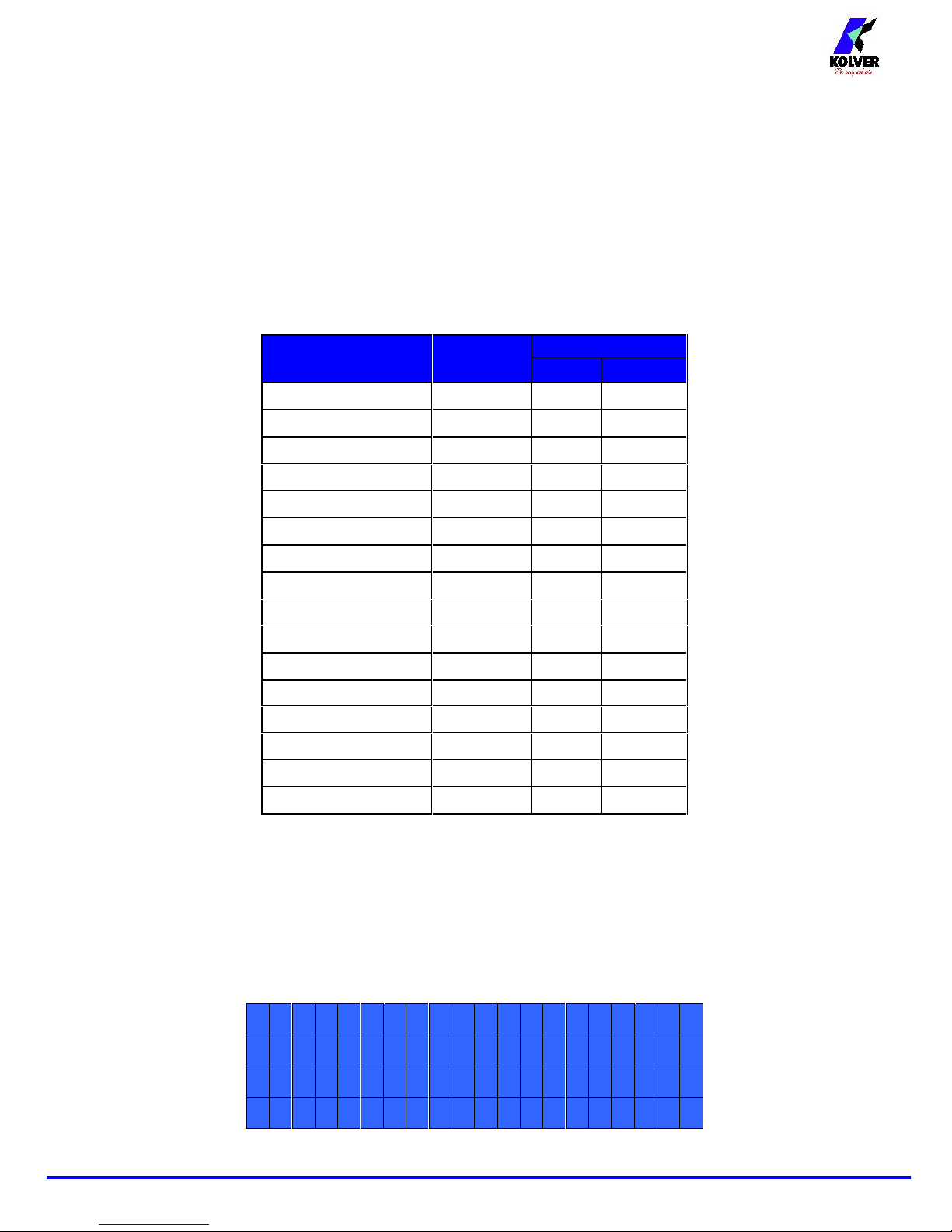
EDU 2AE and EDU 2AE/HPROpower supply and control units are an innovative system for controlling the
torque of any current control MITO and PLUTO electric screwdrivers: MITO15, PLUTO 3, PLUTO 6,
PLUTO 10, PLUTO 15, PLUTO 20, PLUTO 35 snd PLUTO50, either inline, pistol, for automation and
with angle head (only PLUTO). It’s also possible to use the following clutch models: PLUTO 3FR/HS,
PLUTO 5FR and PLUTO 7FR.
EDU 2AE and EDU 2AE/HPROdeliver all the advantages of precision torque control electric tools at a
fraction of the price of transdurized tools.
The state-of-the-art electronic control circuit cuts the power supply to the motor calculating the correct
torque in response to 3 parameters; voltage, frequency and current, according to the selected options.
The AC 90÷260V - 50÷60Hz power supply is converted into 40VDC required by the PLUTO series
screwdrivers through a switching board.
Model
Torque
(Nm)
Speed (rpm)
Min
Max
MITO15
0,2-1,5
450
850
PLUTO 3
0,5-3
370
1300
PLUTO 6
0,85-6
200
850
PLUTO 10
1,5-10
110
600
PLUTO 15
2-15
60
320
PLUTO 20
3-20
50
200
PLUTO 35
3-35
40
140
PLUTO 50
5-502090
PLUTO 6 ANG
0,7-6
200
850
PLUTO 8 ANG
1,5 - 7
110
600
PLUTO 15 ANG
2-15
100
320
PLUTO 20 ANG
3-18
60
200
PLUTO 25 ANG
3-22
40
140
PLUTO 3FR/HS
0,5-2,5
1550
2400
PLUTO 5FR
0,7-5
600
1000
PLUTO 7FR
1,5-7
350
600
IMPORTANT: EDU 2AE and EDU 2AE/HPROare highly accurate units but it is critically important
to select the correct options to ensure that proper torque is being applied. Read the menu description
carefully and in case of doubt please contact Kolver for support information.
Turn the unit on through the on/off switch on the back panel. The unit will carry a general system check and
“waiting connection” will appear on the last line of the display. If the connection with the motor control
board is successful the following screen will be displayed:
KolverS.r.l
.
EDU2A
E
Version2.00
loading..
.
Page 3
Vers. 260918 3
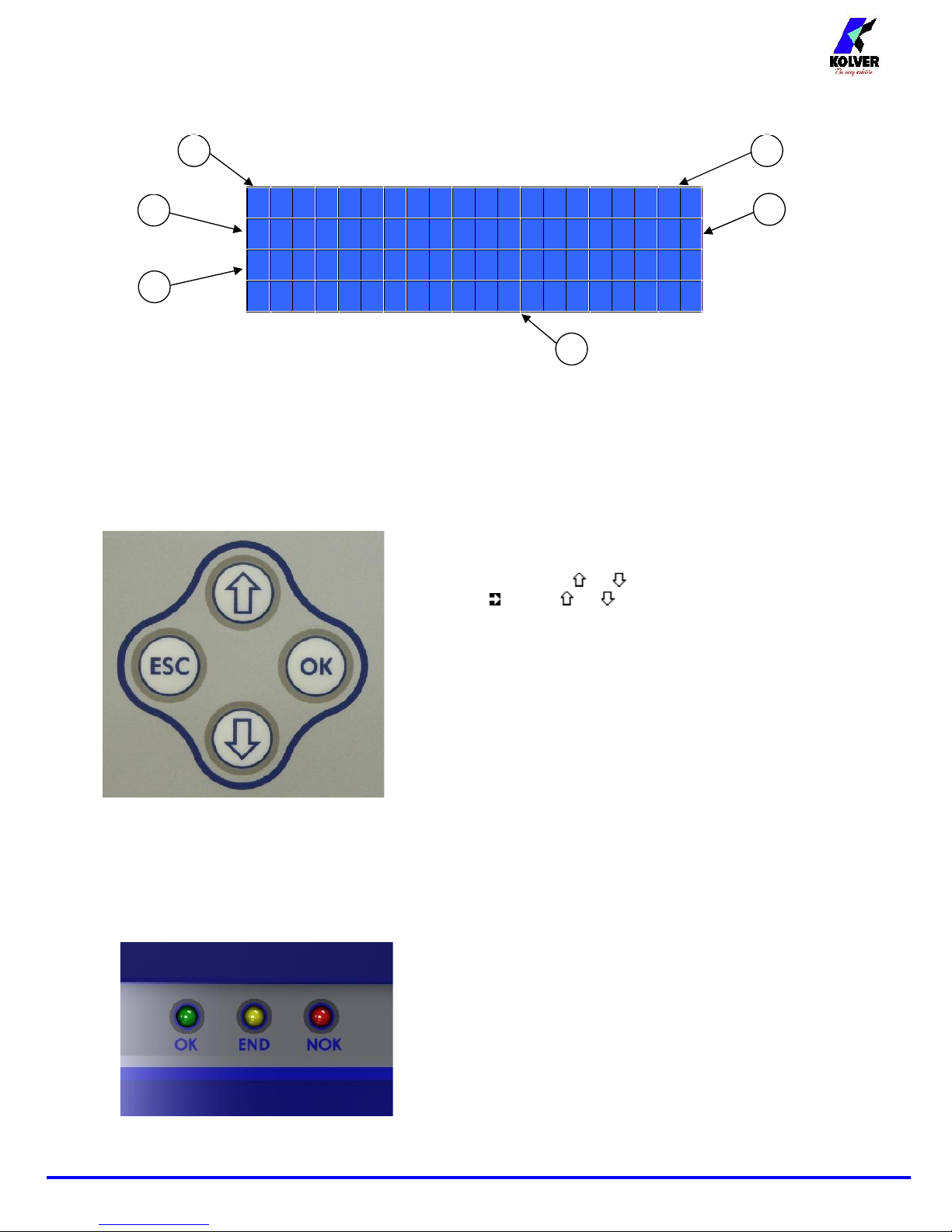
Press any key on the front panel to enter the main screen (see following picture).
PLUTO10T%:20%
S:600rpmS:0/0
3
T:---
ready
1- Screwdriver model
2- Pre-set torque level (percentage)
3- Selected speed
4- Screw count: fastened screws/total screws (model EDU 2AE/HPROonly)
5- Reached torque level (model EDU 2AE/HPROonly) in Nm, in.lbs or kgf.cm.
6- Status bar ( waiting, screwing, errors, etc…)
To enter the menu press ESC for 2 seconds.
Select the line by pressing or then press OK (the symbol
will turn into ). Press or to select the required value and
then confirm through OK (or ESC if you don’t want to save the
value).
The selected value will be immediately operational, even if you
are still in the menu screen. Repeat these operations for all the
parameters you wish to set and then push ESC to return to the
main screen.
FRONT PANEL LED:
GREE LED: Screw OK.
YELLOW LED: Program End (only on EDU 2AE/HPro).
RED LED: error.
1
3
2
4
6
5
Page 4
Vers. 260918 4
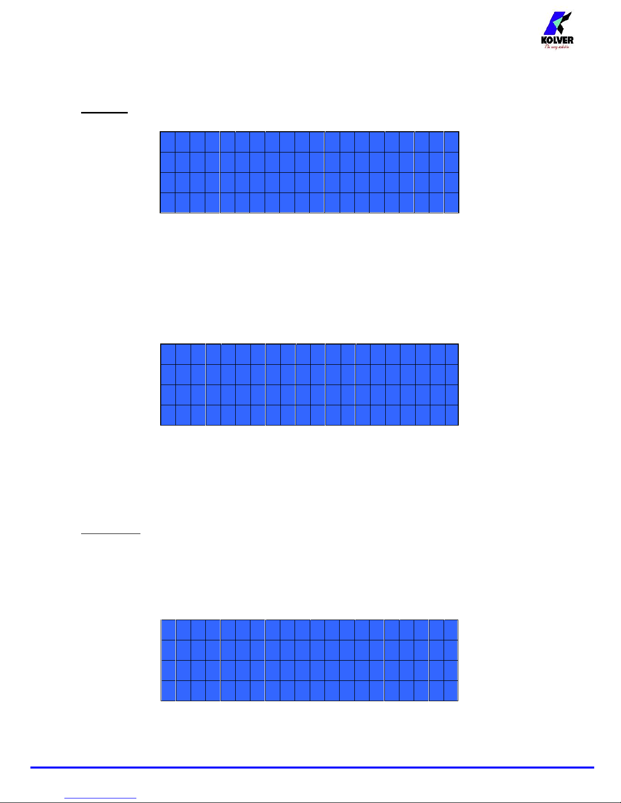
MENU
-----MAIN-MENU-----
-
OKchangeESCquit
Programsettin
g
Unitoptions
Program setting: It indicates the menu section where you can set or modify the fastening parameters.
Unit Options: It indicates the menu section where you can set the language, the password and the unit.
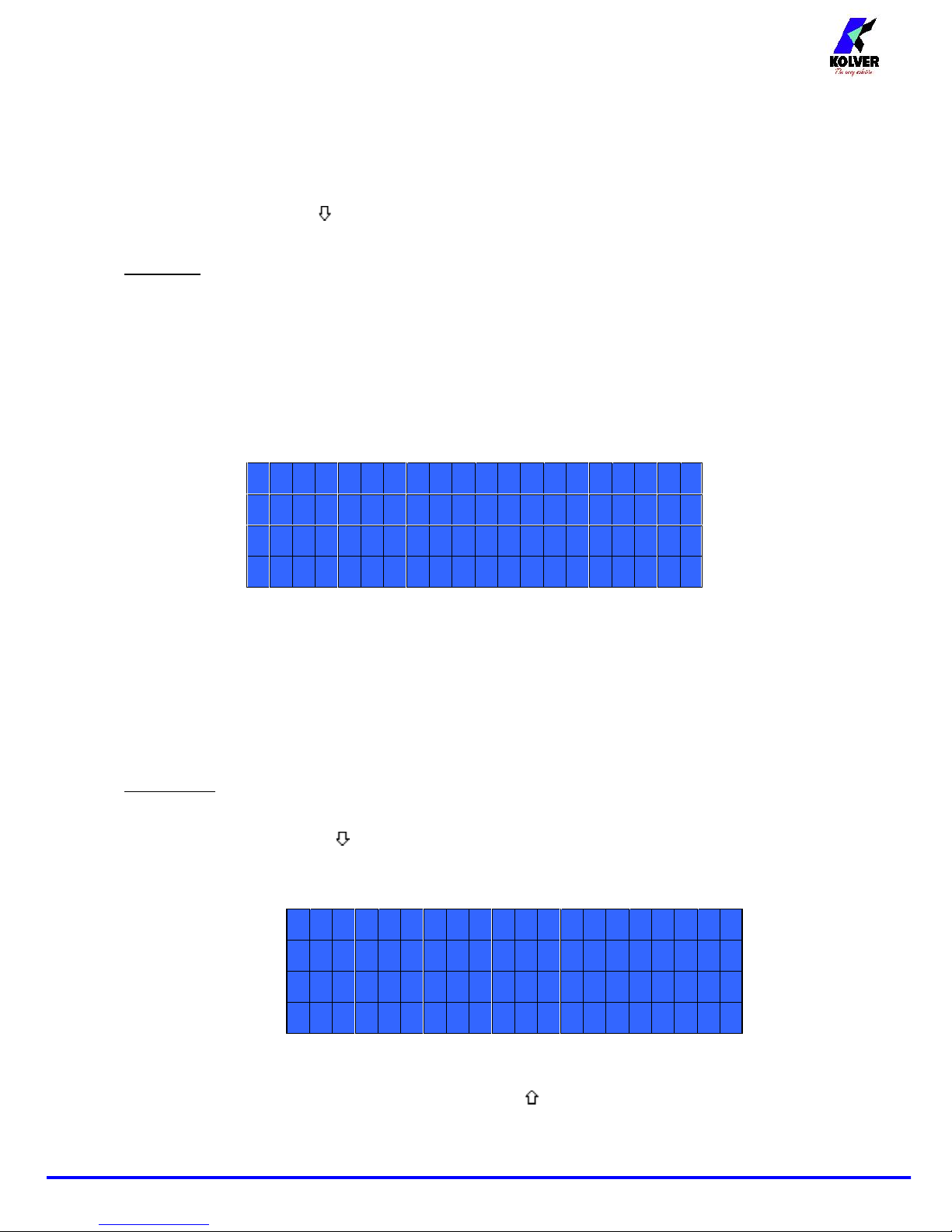
Program setting
The first 12 menu lines are available in the EDU 2AE and EDU 2AE/HP
RO.
Lines from 13 to 20 are only available in the HPROmodel.
--------MENU-------
-
OKchangeESCquit
1)Model:PLUTO10
2)Ramp:0.3s
1) Model: you can select the screwdriver to be used. Your choice will automatically change the default
settings. It’s important to select the correct model you’re going to use since many parameters regarding the
motor software are specific for every single model.
2) Ramp: You can select the slow start time (acceleration) from 0.2 to 3.0 sec. This option is only available
for the screwing phase, while during the unscrewing phase the ramp time is always 0.2 sec. We suggest
using this option with self tapping screws.
ATTENTION: Reaching the torque while the ramp is still on could give as result a different torque level
from the one that results when the ramp is over. This is due to the motor acceleration.
Reaching the torque while the ramp is still on will activate the “screw OK” signal anyway (this option is
useful if you need to tighten screws that are already tightened, the so called “double hit” ).
On the other hand, if you wish to see an error signal during the preset torque in the ramp phase, you can
change the minimum time by setting value which is equal or superior to the ramp value (see point 8).
--------MENU-------
-
3)Torque:MI
N
4)TmFastspd:0.3
s
5)Fastspd:off
3) Torque: you can select the desired torque as a percentage of the torque range of the selected screwdriver.
For example, for a Pluto10, a 50% setting will result in a torque in the area of 4.5 Nm. The torque range is
always referred to the MAX speed. In case you’re not working at maximum speed, the torque range will
Page 5
Vers. 260918 5
progressively lower in order to avoid motor stalling. If the torque level is reached correctly, it will be
showed on the display and you will hear a beep sound, too.
Such torque level is indicated as “ T: ..% ” on the main screen.
4) TM Fast Spd (Time Fast Speed): It indicates how long the screwdriver should turn at the FAST SPEED
speed (see point 6) before switching to “pre-set speed” (lower speed). The “pre-set speed” is the speed set at
point 4. This FAST SPEED time can be set from 0.3 to 10.0 sec.
To disable the function press until you get to OFF. In this case the screwdriver will automatically start at
pre-set speed (see point 6).
CAUTION: The aim of the FAST SPEED is only to speed up the approach time in case of long screws.
Reaching the torque at higher speed will result in inaccurate torque output. To avoid inaccurate torque
values we suggest first to set a shorter time, and then increase it.
Torque reached during the FAST SPEED won’t activate the torque signal and the message “Error FAST
SPEED” will be displayed on the main screen and 2 beep sounds. The red led will turn on, too.
5) Fast Spd (Fast Speed): You can select the speed of the screwdriver during the FAST SPEED. It can be
set between max speed and the pre-set one (see point 4).
This function is available only if the Time Fast Speed is active.
--------MENU-------
-
6
)FinalSpd:600rp
m
7)Runtime:off
8)Mintime:off
6) Final Spd (Final Speed): You can select any speed value of the screwdriver between the maximum and
the minimum specific speed of every single screwdriver (see table with technical data).
7) Run time: You can set the time of a tightening, from OFF to 20.0 sec. When the pre-set time has been
reached, it results in a torque signal.
The couple reached during this time results in a signal of Correct screw. If the correct screw signal is not
required, set the Minimum time up to a value of 'Minimum Time -0.1sec'.
ATTENTION: Max Time must be set at 20.0 sec.
8) Min Time - Minimum Time: You can set this time from 0.1 sec to 'Max time - 0.1s'. To disable the
function select OFF by pressing as many times as needed. (Min time = 0).
Torque reached below the minimum time won’t activate the torque signal and will result in an error
signal. “Below minimum time” will be displayed on the status bar and the red led will light up. You will
hear two beep sounds, too.
9) Max time - Maximum time: You can select the maximum time of tightening. You can set from 'Min
time + 0.1s' to 20.0 sec.
You also can set the Maximum time to OFF by pressing the button when you have reached the value
of 20.0s. In this case the screwdriver turns without any time limit.
--------MENU-------
-
9)Maxtime:20.0s
10)Autorev:of
f
11)Revtorq:MA
X
Page 6
Vers. 260918 6
ATTENTION: If torque isn’t reached by the maximum time, the screwdriver will stop. “Over maximum
time” will be displayed on the status bar and the red led will light up. You will hear two beep sounds, too.
10) Auto Rev: This option will automatically start a reverse after a torque reached/ correct screw signal.
You can set time from 0.1 to 20.0 sec.
To disable the function select OFF by pressing as many times as needed.
ATTENTION: During the reverse, it is necessary to keep the lever or the start signal pressed as long as it
won’t stop. “Correct screw” will be displayed on the status bar and a green led will light up. You will
hear one beep sound, too. In case the lever is released before the end of the reverse, “unfinished screw”
will be displayed and a red led will light up. You will hear two beep sounds, too.
11) Rev torque – Unscrewing torque: You can select the desired torque as a percentage of the torque
range of the selected screwdriver (see point 2). If the torque is set on MAX, the unscrewing torque is about
20% higher than the possible maximum torque, so that it is always possible to unscrew the tightened screw
(we suggest leaving this function on in normal use). If the setting is from MIN to 99% the unscrewing
torque with the same percentage will be equal to the settings of the screwing phase.
ATTENTION: If you’re using open-end wrenches, the unscrewing torque has to be set to MIN value in
order to bring the wrench back to the correct position.
12) Rev speed – Reverse speed: You can select any reverse speed value of the screwdriver between the
maximum and the minimum specific speed of every single screwdriver (see table with technical data).
The following menu is available in the HPROmodel only
13) Pre-Rev. (Pre-reverse): You can set a reverse before a screwing.
Time can set from OFF to 20.0 sec.
ATTENTION: Pre-reverse speed and torque are the same as Auto Rev.
14) PV torque: Period of time in which the screwdriver works at maximum torque before switching to the
torque that has been set by the user. You can set time from 0.1 to 10.0 sec. To disable the function select
OFF by pressing as many times as needed.
This function overlaps other time settings (fast speed, ramp time, minimum time, maximum time) from the
motor start on.
ATTENTION: This function is useful for applications where the prevailing torque is higher than the final
torque (for example trilobal screws or locknuts).
Please use this function with utmost attention because an incorrect use can damage both the assembly
and the screwdriver.
--------MENU-------
-
12)Revspd:600rp
m
1
3)Pre-rev.:of
f
14)PVtorque:off
--------MENU-------
-
1
3)Pre-rev.:of
f
14)PVtorque:off
15)Rotation:right
Page 7
Vers. 260918 7
Torques reached during the max torque time won’t activate the torque signal. “Error tm max torque” will be
displayed and the red led will light up. You will hear two beep sounds, too.
15) Rotation: You can choose between right tightening (standard screws) or left tightening (left threaded
screws). All the other functions will adapt to the selected direction of rotation.
16) Calibration: ON allows to see the torque value on the main screen. OFF doesn’t show the torque
value.
(To modify the calibration parameters see paragraph Torque calibration).
17) Compens – Compensation: This function allows an increase or decrease of the displayed torque after
calibration. The available range is from 0 to ±55 Nm. For example: after calibration (see Torque calibration)
you make a screwing on your assembly and compare the value you see on the main screen display with the
value you see on a torque tester (for example a mini-K or a K model). Let's say you notice that the torque
displayed in the unit EDU 2AE is +0.2 Nm higher than the value indicated on the tester (which is the right
one). In this case you change this value by setting -0.2 Nm so that the value on the screen will be the same
as the value on the tester. If it’s lower than 0.3 Nm, you need to set +0.3 Nm and so on.
18) Torq min – Minimum torque: The minimum torque and maximum torque options allow the user to set
the acceptable torque range for each single application. When the reached torque is inside this range,
“tightening OK” will be displayed on the status bar and the green led will light up. If the reached torque is
outside this range the messages “error minimum torque” or “error maximum torque” will be displayed. You
can set the torque range from 0 to 40 Nm at intervals of 0.01 Nm.
The minimum torque option allows to set the lowest value of the torque range and it’s on if calibration is
'ON'. If calibration is 'OFF' the minimum torque value automatically sets on 0 Nm.
19) Torq Max – Maximum Torque: The minimum torque and maximum torque options allow the user to
set the acceptable torque range for the single application. When the reached torque is inside this range,
“right screwing” will be displayed on the status bar and the green led will light up. The messages “below
minimum torque” or “over maximum torque” will be displayed if the reached torque is outside this range.
You can set the torque range from 0 to 55 Nm at intervals of 0.01 Nm.
The maximum torque option allows to set the highest value of the torque range and it’s on if the calibration
is 'ON'.
20) Screws number: The EDU2AE/HP and the EDU 2AE/HPROcan act as screw counter. You can set the
number of screws from 1 to 99. To disable the function select OFF by pressing as many times as needed.
If the number of correct screws is equal to the number of set screws “Program end” will appear on the status
bar and the yellow led will light up. If the OK/ESC function is disabled (see point 23), “Program end” will
--------MENU-------
-
1
6)Calibration:off
17)Compens:0.00Nm
18)Torqmin:0.00Nm
--------MENU-------
-
18)Torqmin:0.00Nm
1
9)Torqmax:20.00Nm
20)Screwsnum.:3
Page 8

Vers. 260918 8
automatically disappear at next screwing or when you enter the menu. Otherwise, press OK at the end of
each program.
ATTENTION: Every time you enter the menu, the number of screws resets to zero.
Unit Options
1) Language: This option allows to select among 4 languages: English, French, German, Italian, Spanish
and Portuguese.
2) Versions: in this screen you can see the versions of boards mounted inside the unit.
3) Cycles - Number of total screwing/errors done which have been carried out: It shows the number of
fastened screws and occurred errors. This number can’t be modified.
The following menu is available in the HPROmodel only
4) Change password: You can change password (see point 5).
5) Password: If YES, you will be asked for the password to enter the menu. Otherwise select NO.
ATTENTION: Password is only asked to enter the menu for the first time after switching the unit on.
The default password is: 0000.
6) Unit: You can choose between the following units of measurements: Nm, in.lbs and kgf.cm.
7) Press OK: when ON, press OK at the end of each screwing.
When OFF, the control unit resets automatically after a screwing.
8) Press ESC: when ON, press ESC to reset the control unit.
When OFF, the control unit resets automatically after an error signal
----OPTIONS-MENU---
-
OKchangeESCquit
1)Language:EN
2)Version
s
----OPTIONS-MENU---
-
3)Cycles:00000000
0
4)Changepasswor
d
5)Passwor
d
----OPTIONS-MENU---
-
6)Unit:Nm
7)PressOK:off
8)PressESC:of
f
Page 9

Vers. 260918 9
TORQUE CALIBRATION
The torque calibration function allows to view the torque value in Nm or in.lbs or kgf.cm directly on the
display of the control unit.
IMPORTANT: You need a torque tester to proceed, either with static transducer (model minik or K)
or with rotary transducer (model minik-e).
CALIBRATION PROCESS:
1. Select Calibration at point 19 of the menu and press OK.
2. The following screen will appear on the display:
--------MENU-------
-
19)Calibration:on
3. Press OK to confirm. If you choose OFF, calibration will be interrupted and no torque value will be
displayed. You choose ON, calibration will continue and the following screen will be displayed:
--------STEP--1----
-
Enter
percentageMIN
4. Set the first torque level at 20% percentage by pressing .
--------STEP--1----
-
Enter
percentage20%
5. Press OK. You will see:
--------STEP--1----
-
Starttest
OKconfirmESCqui
t
Complete a screwing cycle on the mini k5 and take note of torque value.
Page 10

Vers. 260918
10
6. Press OK, then the display will show:
--------STEP--1----
-
Entertorquevalue:
00.01Nm
Set the torque value by pressing and press OK again to save. You will see:
--------STEP--2----
-
Enter
percentage:22
%
7. Set the percentage of the second torque to 30% by pressing and press OK.
8. Repeat the procedures described on points 4 and 5.
9. When calibration ends, “Setting end” will be displayed. You will hear two beep sounds, too.
Now you are ready to work and see the correct torque on the display.
WARNING:
- Calibration values will be referred to the parameters of the control unit which are set during
calibration, i.e. if you modify speed or torque, the unit will need to be recalibrated. During
calibration when a screwing is not carried out correctly or if for any reasons you’re not sure of the
torque value it is possible to repeat it. A wrong screwing can affect the precision of the calibration.
- Calibration is carried out for two torque levels optionally chosen. The minimum calibration interval
is 5% (example: if I have to work at 50%, I can calibrate at 45% and 55%). In this case, if for any
reasons I need to work at torque percentages which are lower or higher than the min-max ones set
during the calibration, they will be analyzed and displayed anyway but since they won’t be based
on effective data the torque value displayed may be not accurate.
- During calibration it is not possible to go back to the previous screen. Press ESC to stop calibration
and then repeat the screwing cycles.
INTERPRETATION OF ACOUSTIC SIGNALS
The control unit emits sounds which help you understand if the screwing has been carried out correctly or
not. When the torque is reached meeting all the parameters set, the control unit utters a 0.5 sec beep as
confirmation. In case of Program End, the unit will utter other two beeps. Instead, torque reached under min
time, during the Ramp time or under the Fast speed (see error signals on the display) will cause the control
unit to utter three beep sounds.
Page 11

Vers. 260918
11
I/O CONNECTIONS
Page 12

Vers. 260918
12
CN1 CONNECTOR – 10 pin:
On the back panel, in all the EDU 2AE units, there is a 10 pin I/O connector.
PIN
NAME
FUNCTION
OUTPUT
1
+24V
+24V voltage protected. The maximum current consumption is 400mA. CAN NOT BE
USED TO POWER EXTERNAL DEVICES.
2
GND
Common pin. Signals must be taken between this pin (0VDC) and the respective signal
pins.
3
ERROR
Error signal: it activates every time an error occurs.
The red led on the front panel will switch on.
Signal is 24V.
4
MOTOR ON
(\W)
It activates when the motor turns during screwing. Signal is 24V.
5
SCREW OK
Correct screw signal. The green led on the front panel will switch on.
Signal is 24V.
INPUT
6
NOT USED
Not used
Page 13

Vers. 260918
13
7
STOP
MOTOR
Remote motor stop. If it’s activated the message “STOP MOTOR ON” appears on the
display. The motor will stop and won’t start working again as long as the contact is
closed.
8
REVERSE
Remote motor start with torque control while unscrewing.
9
START
Remote start with torque control while screwing.
10
GND
Common pin. Signals must be taken between this pin and the respective signal pins.
CN2 CONNECTOR – 8 pin:
Only on EDU 2AE/HP
RO
PIN
NAME
FUNCTION
OUTPUT
1
GND
Common pin for any input and output. By closing the contact between pin 1 and any of the
other pins to start the function you need. This pin is connected to 0VDC and to the ground.
2
PROGRAM
END
It activates at the end of each program.
3
Not used.
INPUT
4
RESET
If pressed for at least 1 sec, it resets the program you are working in.
5
ESC_EXT
If enabled, (see point 9: OK/ESC), remote ESC key function to reset errors.
6
OK_EXT
If enabled, (see point 9: OK/ESC), remote OK key function to confirm program end.
7
MISSING PIECE
If enabled, it stops the motor, it enables the error signal and ”Error missing piece” is displayed
on the status bar.
8
Not used.
Page 14

Vers. 260918
14
ATTENTION: Output signals are protected from an appropriate circuit. Overload of the available
signals (> 450 mA) or short circuit will result in the stop of the unit. To re-activate signals, it is
necessary to switch off the unit for 5-6 seconds, check connections and output loads then switch the
unit on.
CN3 CONNECTOR (9 pin serial connector – female)
Only on EDU 2AE/HP
RO
PIN
NAME
FUNCTION
1
+15 Vcc
Not used.
2TXSerial transmission.
5
GND
Common pin for any input. Signals must be taken between this pin (GND)
and the other pins of this connector depending on the signal you want to be
printed.
CORRECT SCREWS ON STATUS BAR
“Screw OK” is displayed on the status bar.
The tool has performed a correct screwing,
that is when all the settings have been
fulfilled.
“Run Time OK” is displayed on the status bar.
The tool has performed a correct screwing,
that is when all the settings have been
fulfilled.
“Rev. Torque OK” is displayed on the status bar.
The tool has performed a correct screwing,
that is when all the settings have been
fulfilled.
TROUBLE SHOOTING
ERROR
PROBLEM
SOLUTION
0
“waiting connection” doesn’t turn into “system
ready” after it’s been switched on.
Contact your nearest Kolver dealer.
1
“Error Torque Control” is displayed on the status
bar
Make a new screw. If the error persists, change
the torque and speed settings.
2
“Error fast speed” is displayed on the status bar (the
torque signal is displayed during the fast speed).
For HPROmodel:
If Press ESC function is ON, press ESC for a
new screw; if it’s OFF it automatically resets
Page 15

Vers. 260918
15
3
“Rev. incomplete” is displayed on the status bar (the
displayed torque signal is correct but the set
unscrewing is not complete).
next time you screw.
For 2AE model:
The error automatically resets next time you
screw.
4
“Pre-reverse incompl.” is displayed on the status bar
(the lever has been released before the Pre-Rev. has
been completed).
5
“Under min time” is displayed on the status bar (the
torque signal is displayed below the set minimum
time).
6
“Over maximum time” is displayed on the status bar
(the torque signal is displayed over the set maximum
time).
7
“Error PV torque” is displayed on the status bar (the
torque signal is displayed inside the set maximum
time).
8
“Below min torque” is displayed on the status bar
(the torque signal is displayed below the set
minimum time).
9
“Over max torque” is displayed on the status bar (the
torque signal is displayed over the set maximum
time).
10
“Compensation error” is displayed on the status bar
(the torque value is negative – this is due to an
excessively high negative compensation value)
- Set a higher/lower compensation value.
11
“Error unscrew torque” is displayed on the status bar
(The torque signal is displayed while unscrewing,
but only if it’s set on “max”).
- The screwdriver couldn’t unscrew.
- Avoid motor stalling.
- Unscrewing too heavy.
12
“Protection 12A” is displayed on the status bar (it
happens when current on mosfets of bridge H is >
12 A for at least 1 sec).
- Reduce cycle rate and check settings.
- Avoid motor stalling.
- Unscrewing too heavy.
- Joint too soft.
13
“Protection 14p5A” is displayed on the status bar (it
happens when current on mosfets of bridge H is >
14.5 A for at least 800 ms).
- Reduce cycle rate and check settings.
- Avoid motor stalling.
- Unscrewing too heavy.
- Joint too soft.
14
“Protection 15A” is displayed on the status bar (it
happens when current on mosfets of bridge H is > 15
A for at least 500 ms).
- Reduce cycle rate and check settings.
- Avoid motor stalling.
- Unscrewing too heavy.
15
“OUTPUT DISABLED” is displayed on the status
bar. It is on the protection of the output signals
exceeding the maximum load (400mA).
- Check that the load does not exceed the max
(400mA)
- To reset, restart the unit.
Page 16

Vers. 260918
16
ATTENTION: IF THE OK/ESC OPTION IS DISABLED, ERRORS RESET AT THE FOLLOWING
SCREWING/PROGRAM. OTHERWISE PRESS ESC. IF THE PROBLEM PERSISTS, PLEASE
CONTACT YOUR NEAREST KOLVER DEALER.
SERIAL PORT only on EDU 2AE/HPRO:
EDU 2AE/HP
PRO
control unit is supplied with a serial 9 pin male connector. In this way you can print the
results of each screwing. The transmission characteristics are the following:
9600 (bits per second), 8 (data bits), n (no parity), 1 (bits stop 1).
Connection pin: PIN 2 = TX, PIN 5 = GND
The print string is the following:
RESULT
SCREWDRIVER
MODEL
%
TORQUE
SPEED
TORQUE
SCREW
COUNT
NOTICE
Result = screw evaluation: correct or incorrect.
OK = the torque has been correctly reached, all the selected parameters are satisfied and the control
unit will give out a beep sound of 0.5 sec.
NOK = the torque has been reached during the ramp time or the fast speed (see error table). In this
case, the unit will give out 2 beep sounds and the red led will light up.
Screwdriver model = model of selected screwdriver.
% Torque = percentage of the set torque level.
S: Speed = speed value.
T: Torque = torque value.
Screws: Count = number of screws screwed/number of total screws of the sequence/ program.
Notice = in case of program end, it prints “Program End” or it indicates the type of error (see paragraph:
trouble shooting).
Example of serial print:
Page 17

Vers. 260918
17
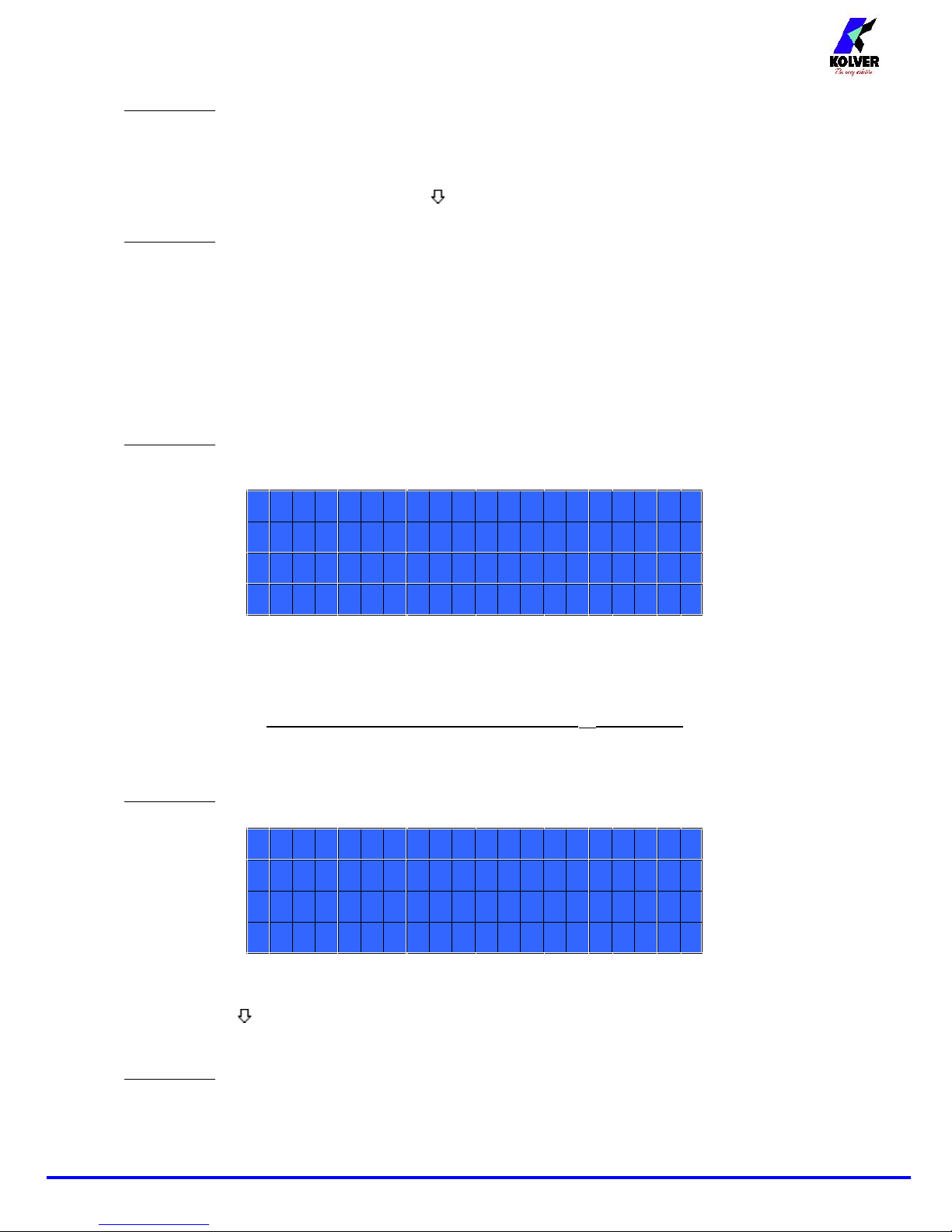
EXPLODED VIEW EDU2AE
Page 18

Vers. 260918
18
SPARE PARTS
Position
Description
Quantity
Code
1
Screw M3x5 TX10
17
872444
2
Upper panel 2AE
1
819003
3
Main PCB
1
852521/SW
4
Switching 48V 600W
1
872490
5
Spacer 15mm - 4,8 mm
4
890004/T
6
Washer M3 h0,5 mm
4
800042
7
Ground cable
1
800090/E
8
Ferrite1872468
9
M3 Brass nut
2
800056/O
10
Front membrane EDU 2AE
1
858004
11
Front panel EDU2AE
1
818002
12
Connector M12 5 pin + nut + ferrite
1
201666/R1
13
Display EDU2AE
1
852522
14
Zn-white nut M3
7
800056
15
Washer M3
5
800041
16
Plastic support
4
800016/B
17
Bottom panel EDU2AE/SW
1
818001/SW
18
Flat 10 vie
1
872438
19
Fuse 3.15A
2
800619
20
Connector I/O 10 pin spacing 3,81
1
800102
21
Filtered plug
1
800718
22
Board support
2
872442
Label1818006/SW
Page 19

Vers. 260918
19
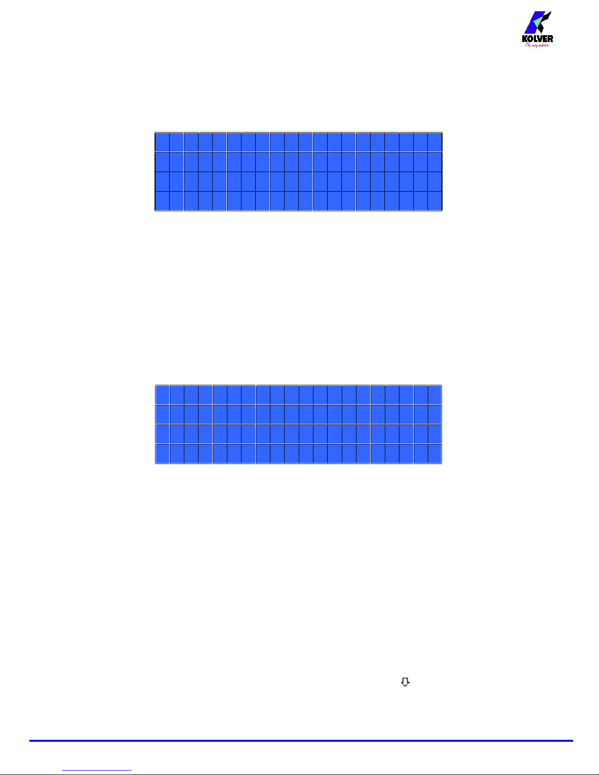
EXPLODED VIEW EDU2AE/HPro
Page 20

Vers. 260918
20
SPARE PARTS
Posizione
Descrizione
Quantità
Codice
1
Screw M3x5 TX10
17
872444
2
Upper panel 2AE
1
819003
3
Main PCB
1
852521/SW
4
Switching 48V 600W
1
872490
5
Spacer 15mm - 4,8 mm
4
890004/T
6
Washer M3 h0,5 mm
4
800042
7
Ground cable
1
800090/E
8
Ferrite1872468
9
M3 Brass nut
2
800056/O
10
Front membrane EDU2AE/HPro
1
858009
11
Front panel EDU2AE
1
818002
12
Connector M12 5 pin + nut + ferrite
1
201666/R1
13
Display EDU2AE/HP
1
852522/HP
14
Zn-white nut M3
7
800056
15
Washer M3
5
800041
16
Plastic support
4
800016/B
17
Bottom panel EDU2AE/HPro/SW
1
818007/PSW
18
Flat 10 vie
1
872438
19
Cap
1
800168
20
Fuse 3.15A
2
800619
21
F serial connector
1
890005/F
22
Spacer M3 M-F
2
872453
23
Connector 8 pin F
1
872464
24
Screw M2x6
2
801004
25
Connector 8 pin M
1
872457
Page 21

Vers. 260918
21
GUARANTEE
1. This KOLVER product is guaranteed against defective workmanship or materials, for a maximum
period of 12 months following the date of purchase from KOLVER, provided that its usage is
limited to single shift operation throughout that period. If the usage rate exceeds of single shift
operation, the guarantee period shall be reduced on a prorata basis.
2. If, during the guarantee period, the product appears to be defective in workmanship or materials, it
should be returned to KOLVER or its distributors, transport prepaied, together with a short
description of the alleged defect. KOLVER shall, at its sole discretion, arrange to repair or replace
free of charge such items.
3. This guarantee does not cover repair or replacement required as a consequence of products which
have been abused, misused or modified, or which have been repaired using not original KOLVER
spare parts or by not authorized service personnel.
4. KOLVER accepts no claim for labour or other expenditure made upon defective products.
5. Any direct, incidental or consequential damages whatsoever arising from any defect are expressly
excluded.
6. This guarantee replaces all other guarantees, or conditions, expressed or implied, regarding the
quality, the marketability or the fitness for any particular purpose.
7. No one, whether an agent, servant or employee of KOLVER, is authorized to add to or modify the
terms of this limited guarantee in any way. However it’s possible to extend the warranty with an
extra cost. Further information at kolver@kolver.it.
26
Connector I/O 10 pin spacing 3,81
1
800102
27
Filtered plug
1
800718
28
Board support
2
872442
Label1818006/SW
 Loading...