

Page 1

DECLARATION OF CONFORMITY
KOLVER S.r.l.
VIA MARCO CORNER, 19
36016 THIENE (VI) ITALIA
Declare that the new tool here described:
Electric screwdriver:
ACC2210 141910
ACC2220 141920
ACC2222 151222
ACC2230 151930
ACC2245 151945
Is in conformity with the following standards and other
normative documents: 2006/42/CE, LVD 2014/35/UE,
EMCD 2014/30/UE, EN 60745-1, EN 60204-1, EN 610006-1, EN 61000-6-3.
It is also in conformity with RoHS II normative
(2011/65/UE).
Name: Giovanni Colasante
Position: General Manager
Person authorized to compile the technical file
in Kolver
Thiene, Jan. 1st 2017 Giovanni Colasante
Operator’s Handbook
IDENTIFICATION DATA OF THE MANUFACTURER
KOLVER S.r.l.
VIA MARCO CORNER, 19/21
36016 THIENE (VI) - ITALIA
IDENTIFICATION DATA OF THE PRODUCT
ELECTRIC SCREWDRIVER MODEL:
ACC2210 141910
ACC2220 141920
ACC2222 151222
ACC2230 151930
ACC2245 151945
THECNICAL DATA OF THE PRODUCT
TENSION: 230V DC
POWER: 30W
SPEED RPM: 950; 2222: 2400; 2245: 450
TORQUE RANGE Nm: 2210: 0,2-1; 2220: 0,7-2
2222: 0,9-2; 2230: 1-3; 2245: 1-4,5
Page 2
GENERAL SAFETY RULES
WARNING: when using electric screwdrivers, basic safety precautions should always be
followed to reduce the risk of fire, electric shock and personal injury. Read all the instructions
below before using the screwdriver and save them.
1. Keep the work area clean and well lit.
2. Do not use the electric screwdrivers in dampt or wet locations or in presence of
flammable liquid or gases.
3. Avoid body conctact with grounded surfaces as pipes, radiators, refigerators etc.
4. Keep children and visitors away from work area.
5. When not in use screwdrivers should be stored in dry and locked-up place and out of
the reach of children.
6. Do not use the screwdrivers for purposes or works not intended.
7. Dress properly. Do not wear loose clothing and jewelry. Wear protective hair
covering to contain long hair.
8. Never carry the screwdriver by cable or pull it to disconnect it from socket.
9. Use clamps or a vice to hold work.
10. Keep proper footing and balance at all times.
11. Inspect tool cable periodically and, if damaged, have it repaired or replaced by
authorized service facility. Always keep handles dry, clean and free from oil and
grease.
12. Disconnect tools from power supply before any operation of servicing, when changing
accessories and when you do not use them.
13. When screwdriver is used outdoors,only operate with extension cords intended for use
outdoors and so marked.
14. Pay attention while working. Do not operate screwdriver when you are tired.
15. Always check the screwdriver is not damaged before using it. Defective switches must
be replaced by authorized service center. Never use tools that cannot be turned on or
off by the switch.
16. The use of any other accessory other than recommended in this operating instruction
may represent a risk of personal injury.
17. Have the screwdriver repaired only by authorized and expert people.
Failing to do so may represent a serious danger.
WARNING: before connecting the control unit and power supply to the socket, please check
the voltage you are using is the same indicated on the label of the unit itself.
1. APPLICATIONS
Kolver electric screwdrivers are designed to tighten to preset torque values any fasteners up to
M5. Tabel 1 will help you to identify the capacity and the torque range of each model.
Precision assembly industries in the field of electronics, electric appliances, toys, glasses frame
and so on, are the natural users of electric screwdrivers.
Model
Capacity
Speed RPM
Torque range [Nm]
ACC2210M3950
0,2 - 1,0
ACC2220M4950
0,7 - 2,0
ACC2222M42400
0,9 - 2,0
ACC2230M5950
1,0 - 3,0
ACC2245M5450
1,0 – 4,5
Page 3

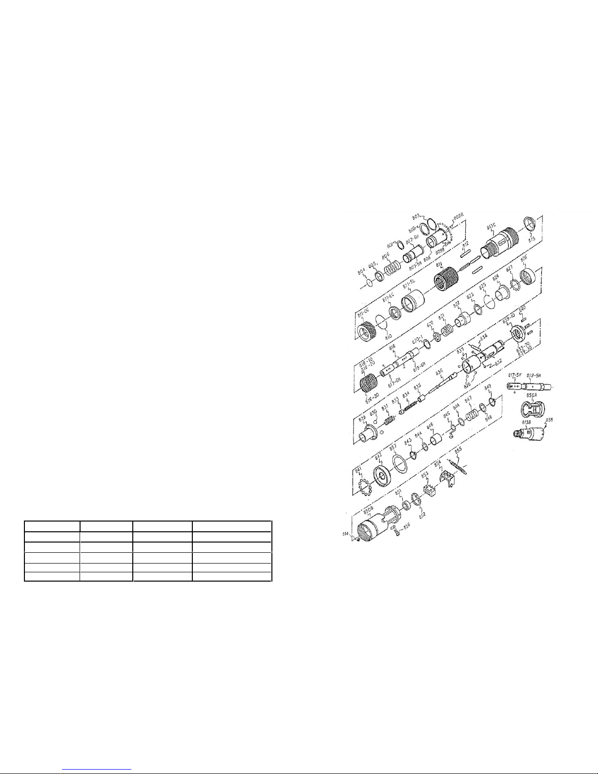
SPARE PARTS LIST ACC
REF
DESCRIPTION
CODE
REF
DESCRIPTION
CODE
M3076-10
Motor 2210
219210
961
Fixing screw
200039
M3076-20
Motor 2220
219220
962
Isolation washer
219962
M3076-30
Motor 2230 & 2222
219230
963
Shell (base)
219963
M-301
Motor cover
219301
964
Shell (cover)
219964
M-302
Bering
220080
965
Trigger start
219965
M-303
Washer
219303
966
Spring
219966
M-304/1
Magnet 2210
219304
967
Flat screw
219967
M-304/2
Magnet 2220
219314
968
Screw
219968
M-304/3
Magnet 2230 & 2222
219324
969
Hanger
219969
M-305
Steel housing 2210 &2220
219305
970
Microswitch
219970
M-305/1
Steel housing 2230 & 2222
219350
971
Start switch
219971
M-306
Rotor 2210 & 2220
219306
972
For-Rev slide switch
219972
M-306/1
Rotor 2230 & 2222
219360
973
P.C.B.
219973
M-307
Carbon brush
219307
974
Cable joiner
219974
M-308
Carbon brush cover
219308
975
Cable
219975
M-309
Brushes seat 2210 & 2220
219309
976
Plug
219976
M-309/1
Brushes seat 2230 & 2222
219390
M-310
Stop spring 2210 & 2220
219310
G602836
Internal gear
219836
G-154
Upper reduction plater
219154
G-155
Planet gear
219155
G-156
Washer
219156
G-157
Lower reduction plate
219157
G-191
Main gear
219191
G-192
Planet gear
219192
G-193
Washer
219193
G-194
Steel washer
219194
G-195
Washer ring
219195
F1
Separate seat
219957
F2
Bearing
210080
F3
Fan
219959
F4
Washer
219960
Page 4

SPARE PARTS LIST ACC
REF
DESCRIPTION
CODE
REF
DESCRIPTION
CODE
801
Clip
219801
826
Thrust sheet
219826
802
Clip
219802
827
Steel ball
219827
803
Washer
219803
828
Steel ball
219828
804
Clip
219804
829
Idling ring
219829
805
Lining ring
219805
830
Steel ball d. 5mm
219830
806
Spring
219806
831
Main shaft return spring
219831
807-5H
Bit control ring 5mm
219807
832
Steel ball
219832
807-6H
Bit control ring 1/4
219880
833
Stopping ball
219833
808-5H
Main shaft thrust sleeve 5mm
219808
834
Central control rod spring
219834
808-6H
Main shaft thrust sleeve 1/4
219881
835
Control rod sliding sleeve
219835
809-B
Steel ball
219809
836
Central control rod
219836
809-R
Roller ball
219882
837
Main shaft-output
219837
810
Stop ring
219810
838
Pin
219838
811
Torque nut fixing type
219811
839-10
Upper clutch
219839
811-LC
Thread of torque nut
219883
839-20
Upper clutch
219893
811-SL
Torque nut outer slide sleeve
219884
839-30
Upper clutch
219894
811-0C
Torque adjusting locker
219885
840
Roller ball
219840
812
Pin
219812
841
Steel ball
219841
813-B
Torque nut seat
219813
842
Upper clutch thrust cover
219842
813-C
Torque nut seat
219892
843
Clip
219843
814
Fixing screw
219814
844
Washer
219844
815
Torque spring bottom seat
219815
845
Hook
219845
816-10
Torque spring 10 Kg/cm
219816
846
Shaft liner
219846
816-20
Torque spring 20 Kg/cm
219886
847
Spring
219847
816-30
Torque spring 30 Kg/cm
219887
848
Washer
219848
817-5H
Steel ball d. 2.5mm
219817
849
Clip
219849
817-6H
Steel ball d. 2mm
219888
850-A
Upper mechanical seat
219850
818
Steel ball d. 2.38mm
219818
850-B
Upper m. seat wear improved
219891
819-5H
Main shaft output 5mm
219819
851
Bearing
219851
819-6H
Main shaft output 1/4
219889
852
Stop ring
219852
820
Release ring spring seat
219820
853
Micro switch
219853
820-1
Stop ring
219890
854
Micro switch seat
219854
821
Release ring spring
219821
855
M. switch seat pull spring
219855
822
Release ring
219822
856
Earth connection screw set
219856
823
Washer
219823
857
Schock absorber
219857
824
Lower clutch thrust sleeve
219824
858
Screw
219858
825
Stop ring
219825
2. USE
The screwing system is composed by a screwdriver and a cable with schuko plug. To install
it please follow the instructions.
a. Pull the collect ring of the quick change chuck, insert the desired bit into the ¼” seat and
release the ring. The bit is automatically locked into position .
b. Connect the screwdriver plug to a mains supply socket 230v- 50Hz .
c. Put the bit head firmly into the fastener head, position the forward/ reverse selector upside
.
- PUSH AND LEVER COMBINATION FUNCTION (switch on the PL position).
Apply axial pressure through the tool onto the fastener. Then, press the trigger to start
tightening the fastener. When the preset torque is reached, the tool stops automatically.
- PUSH START FUNCTION (switch on the P position) .
Make sure to keep the tool bit straight onto the fastener. Then, push to start tightening
(same as PL function but no need to press the trigger).
IMPORTANT: For each second of operation the motor needs 3 seconds of rest, as
indicated on the tool label (1s/3s). Failure to do so may result in motor overheating and
eventually damage and will be considered as a misuse. Our warranty will not apply.
3. ACCESSORIES
Use only ¼” ISO 1173 bits and power bits.
4. ADJUSTING THE CLUTCH
The torque values is adjusted by changing the tension of the clutch spring. The torque can be
increased by turning nut #811 clockwise and decreased by turning it anticlockwise.
To check the torque value we suggest the use of KOLVER K and miniK torque tester series.
4. MAINTENANCE
The D.C. motor is equipped with two carbon brushes 8mm long. When their lenght is about
5mm it is time to replace them with new ones as per the following instructions.
a. Unscrew cover # M-308 and let the carbon brush come out of its seat.
b. Insert a new carbon brush and screw back cover # M-308.
The average life of carbon brushes is approx 1 milion cycles.
Note
The sound level generated by Kolver electric screwdrivers is always lower than 70dB(A).
The vibrations transmitted to operator’s hand are lower than 2,5m/s². In particular the
exposition to vibrations is lower than 1m/s² for operators who make up to 4200 screwing
cycles per day.
Page 5

GUARANTEE
1. This KOLVER product is guaranteed against defective workmanship or materials,
for a maximum period of 12 months following the date of purchase from
KOLVER, provided that its usage is limited to single shift operation throughout
that period. If the usage rate exceeds of single shift operation, the guarantee period
shall be reduced on a prorata basis.
2. If, during the guarantee period, the product appears to be defective in
workmanship or materials, it should be returned to KOLVER or its distributors,
transport prepaied, together with a short description of the alleged defect.
KOLVER shall, at its sole discretion, arrange to repair or replace free of charge
such items.
3. This guarantee does not cover repair or replacement required as a consequence of
products which have been abused, misused or modified, or which have been
repaired using not original KOLVER spare parts or by not authorized service
personnel.
4. KOLVER accepts no claim for labour or other expenditure made upon defective
products.
5. Any direct, incidental or consequential damages whatsoever arising from any
defect are expressly excluded.
6. This guarantee replaces all other guarantees, or conditions, expressed or implied,
regarding the quality, the marketability or the fitness for any particular purpose.
7. No one, whether an agent, servant or employee of KOLVER, is authorized to add
to or modify the terms of this limited guarantee in any way. However it’s possible
to extend the warranty with an extra cost. Further information at kolver@kolver.it
 Loading...