

Kolpin Powersports 180cc Service Manual
Kolpin Powersports
180cc Service
Manual

CONTENTS
FIG.-01
INFORMATION.……………………….…………….
………………………………
1
FIG.-02
VEHICLE INSPECTION………………………….......
………………………………
6
FIG.-03
OVERVIEW…………………………………….……..
………………………………
18
FIG.-04
FENDER..……………………………………...……...
………………………………
19
FIG.-05
FUEL &OIL TANK……………..……………………..
………………………………
22
FIG.-06
MUFFLER…………………………………………….
………………………………
23
FIG.-07
HANDLEBAR………………………………………...
………………………………
24
FIG.-08
ENGINE REMOVAL…….……………………………
………………………………
26
FIG.-09
TIRE AND RIM……………….………………………
………………………………
27
FIG.-10
FRONT BRAKE………………………………………
………………………………
28
FIG.-11
REAR BRAKE………………………………………...
………………………………
30
FIG.-12
SUSPENSION…………………………………………
………………………………
32
FIG.-13
SUSPENSION ARM& KNUCKLE…..……………….
………………………………
33
FIG.-14
REAR AXLE ASS’Y……...…………………………..
………………………………
34
FIG.-15
STEERING SHAFT…..…………….…………………
………………………………
35
FIG.-16
FRAME COMP………………………..………………
………………………………
36
FIG.-17
LIGHT………………………………..………………..
………………………………
37
FIG.-18
ENGINE DISASSEMBLY .……..…………………….
………………………………
39
FIG.-19
ELECTRIC SYSTEM……….………………………..
………………………………
68
FIG.-20
TROUBLE SHOOTING………………………………
………………………………
73
FIG.-21
MAIN WIRE DRAWING…………………………….
………………………………
85

1
FIG-01 INFORMATION
SAFETY
GASOLINE
Gasoline is extremely flammable and is explosive under certain condition. Do not smoke or allow sparks or
flames in your work area.
CARBON MONOXIDE
Never run the engine in a closed area. The exhaust contains poisonous carbon monoxide gas that may cause loss
of consciousness and lead to death.
BATTERY ELECTROLYTE
The battery electrolyte contains sulfuric acid. Protect your eyes, skin and clothing. If you come into contact with
the electrolyte, flush the area thoroughly with water. If you get the electrolyte in your eyes, flush with water and
contact a doctor immediately.
HOT PARTS
Engine and exhaust pipe become very hot and remain hot for one hour after the engine is run. Wear insulated
gloves before handling these parts.
USED ENGINE /GEAR OIL
Used engine oil and gear oil may cause skin disease after repeated contact with the skin for long periods. Keep out
of reach of children.
NOTES
All information, illustrations, directions and specifications included in this publication are base on the latest
product information available at the time of approval for printing.
No part of this publication may be reproduced without written permission.

2
FIG-01 INFORMATION
SPECIFICATIONS
TYPE
OVERLAND – 180CC
ENGINE TYPE
Air-Cooled 4-stroke, with Oil Cooler, Horizontal Stroke
CYLINDER NUMBER
1
DISPLACEMENT
169 cc
BORE STROKE
∮ 61×57.8mm
COMPRESSION RATIO
9.1:1
MAX. TORQUE
6.37 Nm@4403 rpm
CARBURETOR
MIKUNI 180
STARTING
Electric/ Kick back-up
LUBRICATE
Forced pressure and wet sump
LUBR. CAPABILITY
1 Liter
TRANSMISSION
Automatic (C.V.T V-belt system)
SUSPENSION
FRONT
Single A-Arm
REAR
Single Swing Arm
BRAKE
FRONT
Drum
REAR
Disc
TIRE
FRONT
21× 7- 10”
REAR
21× 10- 8”
OVERALL DIMENSION
1740×990×1060 mm
WHEELBASE
1065 mm
DRY WEIGHT
165 kg
FUEL
Unleaded Gasoline
FUEL CAPABILITY
8 Liter
Ignition
Capacitor Discharge
Air Cleaner
AE-9
*Specifications subject to change without notice.
3
FIG-01 INFORMATION
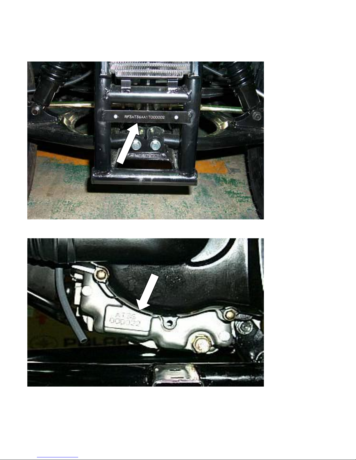
SERIAL NUMBER
The frame serial number is stamped on the front frame.
The engine number is stamped under the crankcase.

4
FIG-01 INFORMATION
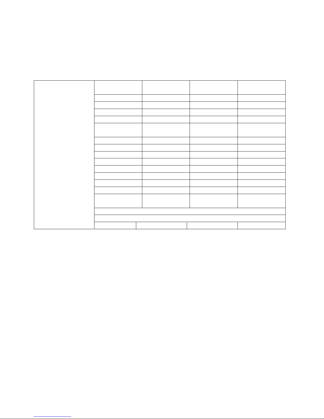
TORQUE VALUES
STANDARD
5mm bolt and nut
6mm bolt and nut
8mm bolt and nut
10mm bolt and nut
12mm bolt and nut
ENGINE
Cylinder head nut
Spark plug
Cylinder head bolt
Alternator bolt
FRAME
Handlebar upper holder bolt
Throttle housing cover screw
Steering shaft nut
Steering shaft holder bolt
Wheel rim bolt
Tie rod lock nut
King pin nut
Handlebar lower holder nut
Front wheel bolt
Front axle nut
Front brake arm nut
Rear brake arm nut
Rear axle nut
Rear wheel bolt
Exhaust muffler mounting bolt
Engine hanger bolt
Rear axle holder bolt
Swing arm pivot nut
Rear shock absorber mounting nut
5 N.m (3.5 lbs.ft)
10 N.m (7.2 lbs.ft)
22 N.m (16 lbs.ft)
35 N.m (25 lbs.ft)
55 N.m (40 lbs.ft)
28 N.m (20.7 lbs.ft)
12 N.m (8.9 lbs.ft)
20 N.m (14.8 lbs.ft)
8 N.m (5.9 lbs.ft)
24 N.m (17.7 lbs.ft)
4 N.m (2.9 lbs.ft)
50 N.m (36.9 lbs.ft)
33 N.m (24 lbs.ft)
18 N.m (13.3 lbs.ft)
35 N.m (25.8 lbs.ft)
40 N.m (29 lbs.ft)
40 N.m (29.5 lbs.ft)
24 N.m (17.7 lbs.ft)
60 N.m (44 lbs.ft)
4 N.m (3.0 lbs.ft)
7 N.m (5.2 lbs.ft)
60 N.m (44.3 lbs.ft)
24 N.m (17.7 lbs.ft)
30 N.m (22.1 lbs.ft)
30 N.m (22 lbs.ft)
90 N.m (65 lbs.ft)
90 N.m (65 lbs.ft)
45 N.m (33 lbs.ft)

5

6
FIG-02. Vehicle Inspection
MAINTENANCE DATA
SPARK PLUG
Spark plug cap
Recommended spark plugs
Throttle lever free play:
Idle speed
Brake lever free play:
Drive chain slack
Front/rear tire size
Front/rear tire pressure
Toe-in
TORQUE VALUES
Spark plug
Tie-rod lock nut
ENGINE OIL
Viscosity:
GEAR LUBRICATION OIL
Viscosity:
0.6-0.7mm
NGK C7HSA or CR7HSA
5-10mm
1800rpm
10~20mm
15-25mm
21x7-10” / 21x10-8”
3±0.3psi (0.15 kgf/cm2)
5±10mm
12-19 N.m
35-43 N.m
SAE 15W-40
SAE 85W-140
7
FIG-02. Vehicle Inspection
MAINTENANCE SCHEDULE
The maintenance intervals in the follow table are based
upon average riding conditions. Riding
in unusually dusty areas requires more frequent
servicing.
Service Item
Initial Service
(First 30 hours)
Every 100 hours
Every 200 hours
Every 300 hours
ENGINE OIL
R R
GEAR OIL
R R
FUEL FILTER
R
AIR VLEAN FILTER
R
ENGINE OIL
FILTER
C
CARBURETOR
I
SPARK PLUG
C
VALVE GAP
A
IGNITION TIMING
A CHAIN
A
BATTERY
I
DRIVE BATTERY
I CLUTCH
I
THROTTLE
OPERATE
I
TIRE PRESSURE
Check before riding each time
BRAKE SYSTEM
Check before riding each time
NUTS/BOLTS
T
A: Adjust C: Clean I: Inspection R: Replace T: Tighten
8
FIG-02. Vehicle Inspection
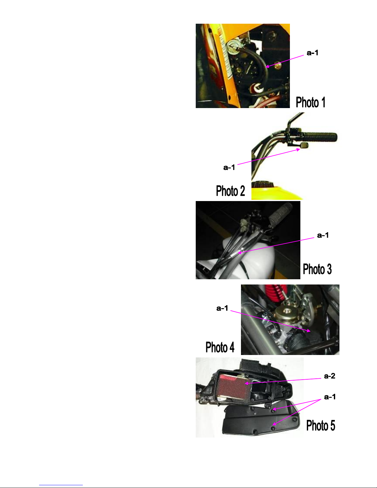
FUEL TUBE
Inspect the fuel lines for deterioration, (a-1)
damage or leakage and replace if necessary.
(Photo 1)
THROTTLE OPERATION
1. Inspect for smooth lever operation, full opening and
automatic full closing in steering positions.
2. Inspect for deterioration, damage, cuts and nicks, or
kink in the throttle cable, replace it if necessary.
3. Check the throttle lever, free play should be not more
than 5-10 mm at the tip of the throttle lever. (a-1)
4. Disconnect the throttle cable at the upper end.
Lubricate the cable with commercially lubricant to
prevent premature wear.
(Photo 2)
THROTTLE CABLE ADJUSTMENT
Slide the rubber cap of the adjuster off the throttle
housing, loosen the lock nut and adjust the free play of
the throttle lever by turning the adjuster on the throttle
housing. Inspect the free play of the throttle lever. (a-1)
(Photo 3)
AIR CLEANER MAINTENANCE
1. Loosen the screw and remove the air cleaner from
carburetor. (a-1)
2. Disassemble the air cleaner cover and body.
3. Remove the air cleaner element and screen.
Install the new one. (a-2)
4. Assemble the air cleaner body and cover and
re-attach to the carburetor with screw.
(Photo 4,5)
9
FIG-02. Vehicle Inspection
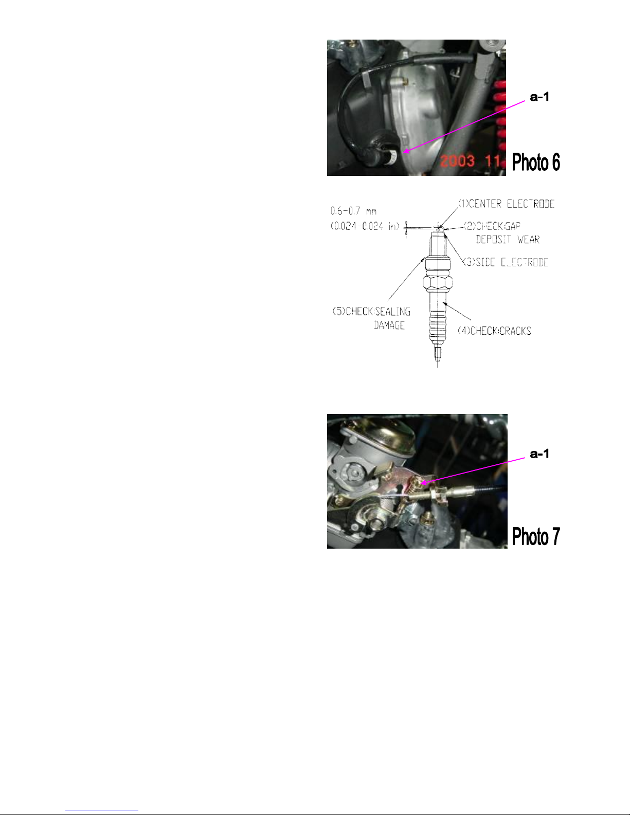
SPARK PLUG
The spark plug is located at the front of the engine.
1. Disconnect the spark plug cap and remove the spark
plug (a-1)
2. Visually inspect the spark plug electrode for wear or
cranks in insulator. Replace if needed
3. The center electrode should have square edges and
the side electrode should have a constant thickness.
4. Discard the spark plug if there is apparent wear or if
the insulator is cracked or chipped.
5. Measure the gap with a wire-type feeler gauge and
adjust if necessary by carefully bending the side
electrode.
6. Check the sealing washer and replace with a new one
if damaged.
7. With the sealing washer attached thread the spark
plug in by hand to prevent cross threading. Tighten the
spark plug. TORQUE: 12-19 N-m
SPARK PLUG GAP: 0.6~0.7 mm
RECOMMENDED REPLACEMENT PLUG:
NGK CR7HSA
(Photo 6)
IDLE SPEED SETTING
1. Inspect and adjust the idle speed after all other engine
maintenance items have been performed and are
within specifications. The engine must be warm for
accurate idle speed inspection and adjustment.
2. Warm up the engine for about ten minutes and
connect a tachometer.
3. Turn the throttle stop screw as required to obtain the
specified idle speed. (a-1)
IDLE SPEED: 1700 ± 100 rpm
(Photo 7)
10
FIG-02. Vehicle Inspection
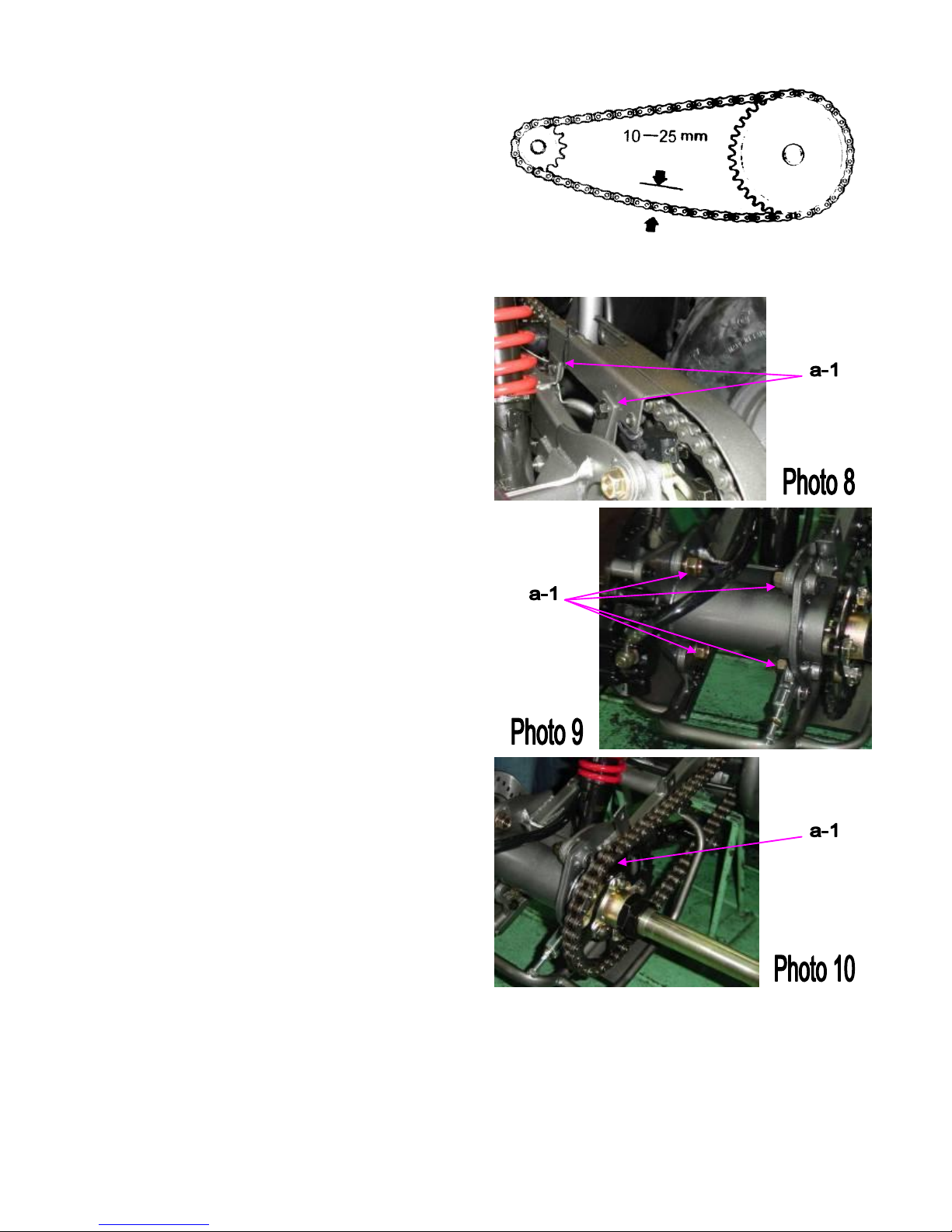
DRIVE CHAIN ADJUSTMENT
Stop ATV and shift transmission into neutral. Inspect
the chain slack midway between the sprockets. The
standard is 10-25 mm (5/8-1 inch).
If needed remove the chain protectives cover and adjust
the chain slack. (a-1)
(Photo 8)
Loosen the axle holder lock nut then adjust the drive
chain slack by turning the adjusting nut. Tighten the
axle holder lock nut. (a-1)
Torque = 90N.m (65 Ft. lbs)
(Photo 9)
When the drive chain becomes very dirty, it should be
removed, cleaned and lubricated with the specified
lubricant.
1. Clean the drive chain with kerosene and wipe it dry
2. Inspect the drive chain for possible wear or damage.
3. Replace the chain, if it is worn excessively or
damaged.
4. Inspect the sprocket teeth, if it has excessive wear or
damage, replace if needed.
5.Use a commercial chain lubricant to lubricate the
drive chain, replace and adjust the slack as described
above. (a-1)
(Photo 10)
11
FIG-02. Vehicle Inspection
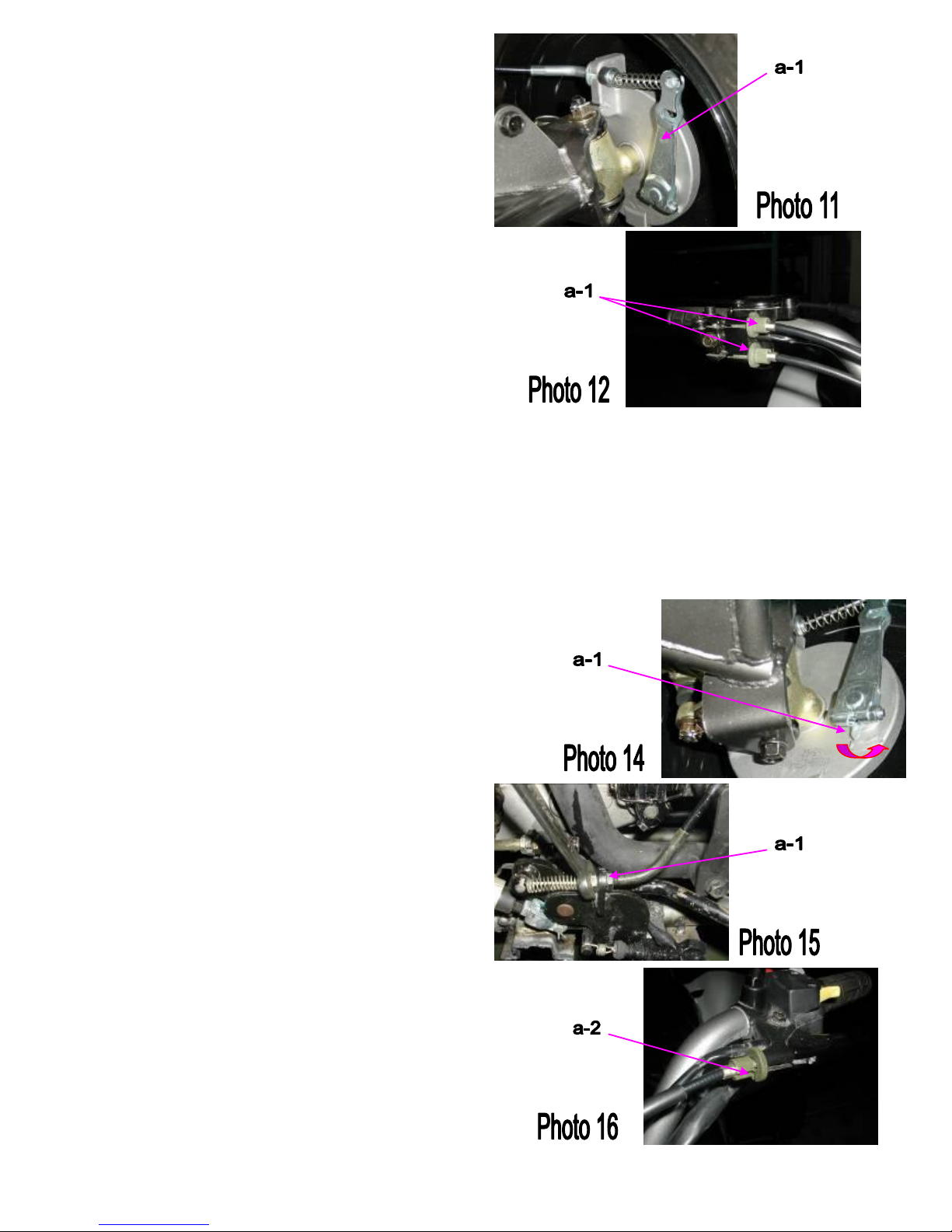
FRONT BRAKE ADJUSTMANT
The front brake has two cables to control right and
left side brake simultaneously.
You could adjust the gap of the front brake (a-1).
(Photo 11)
Loosen the fix nut (a-1) and adjust the position of cable
to proper situation.
(Photo 12)
Inspect the front brake lever and cable for excessive
play or other damage.
Replace or repair if necessary.
Measure the free play of the brake lever at the end of
the lever. The standard is 10~20 mm.
Adjust the free play of the front brake lever by turning
the adjuster on the brake lever assembly.
The brake shoe uses an arrowhead on the front brake
plate to indicate pad condition.
When the arrowhead is beyond the wear limits shown,
the brake shoes need to be changed. (a-1)
(Photo 14)
REAR BRAKE ADJUSTMENT
Install the rear brake cable fixing nut set & adjust the
brake cable.
1. Spin the gap adjuster on the left lever to the shortest
position. (a-1)
2. Adjust the adjusting screw and keep the gap within
2-3 mm. (a-2)
(Photo 15,16)
12
FIG-02. Vehicle Inspection
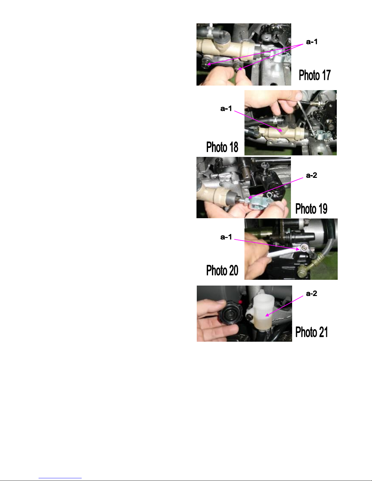
REAR BRAKE ADJUSTMENT
Remove the rear brake locking nut set and the brake
cylinder mounting bolts (a-1)
(Photo 17)
The setup of the adjusting nut of the brake pump(a-1):
1. The brake pedal should be in the highest location
with the returning spring functioning correctly.
2. The adjusting nut changes the distance between the
brake master cylinder and the hydraulic
cylinder-driving rod. Make sure the nut touches the
surface of the rod and revolve back 1 turn (360˚).
Confirm the nut location and spin the rod until the
nut is locked (a-2).
(Photo 18,19)
NOTICE:
Do not over-adjust, it might result in the
brake pump malfunction and cause the brake to activate.
1. Remove any air in the brake line to prevent
the brake from losing power(a-1).
2. Open the brake oil tank (a-2) and loosen the drain
screw of the brake caliper without pumping the brake.
In normal operation the brake oil could drain
automatically; please try this for couple times for
confirmation. If it doesn’t work, adjustment of the brake
pump may be required.
(Photo 20,21)
NOTICE:
Verify oil amount is above the minimum level.
Press on the brake pedal or pull the brake lever several
times then hold pressure, release the drain screw and
lock it on immediately until no air bubbles are found in
the brake oil.
Be careful for splashing oil when bleeding the brakes.
13
FIG-02. Vehicle Inspection
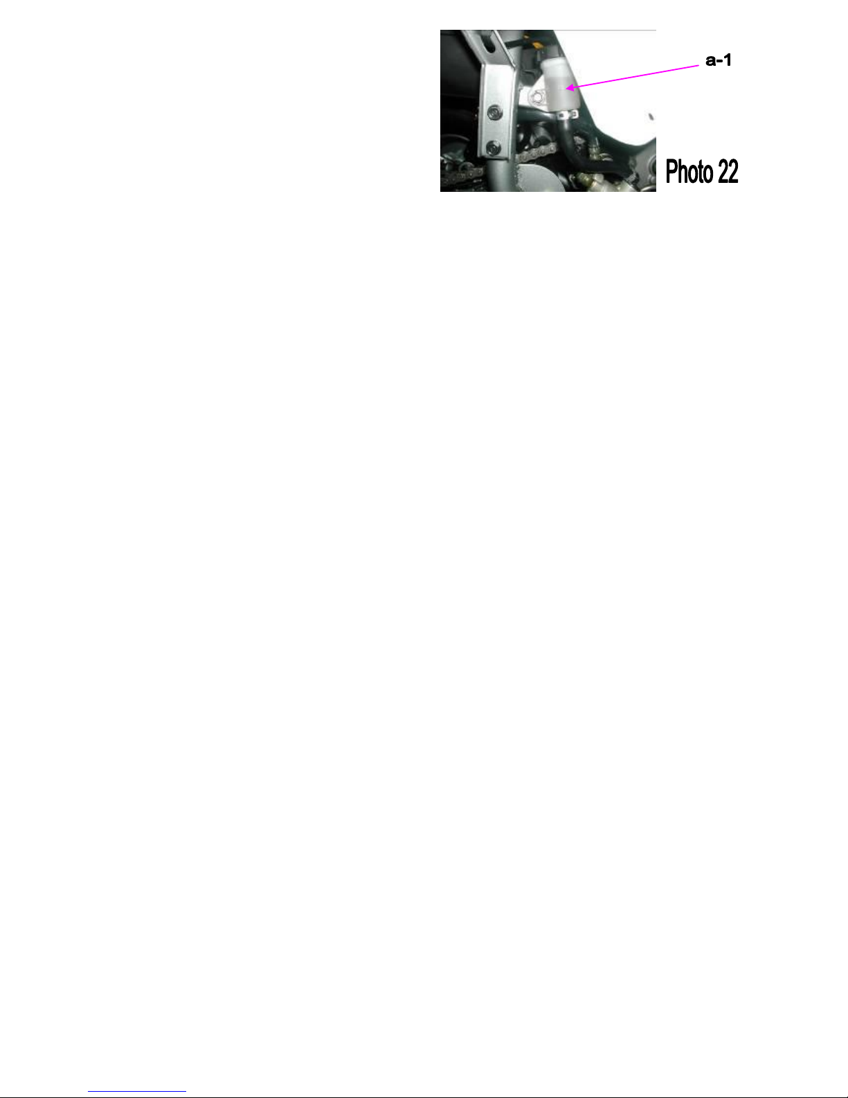
REAR BRAKE FLUID REFILLING METHOD
1. Remove the oil tank cover (a-1).
2. Refill with the recommended DOT-3 brake fluid until
the level reaches the upper limit.
(Photo 22)
CAUTION
Be careful when filling the brake oil tank to
to avoid spilling the oil
14
FIG-02. Vehicle Inspection
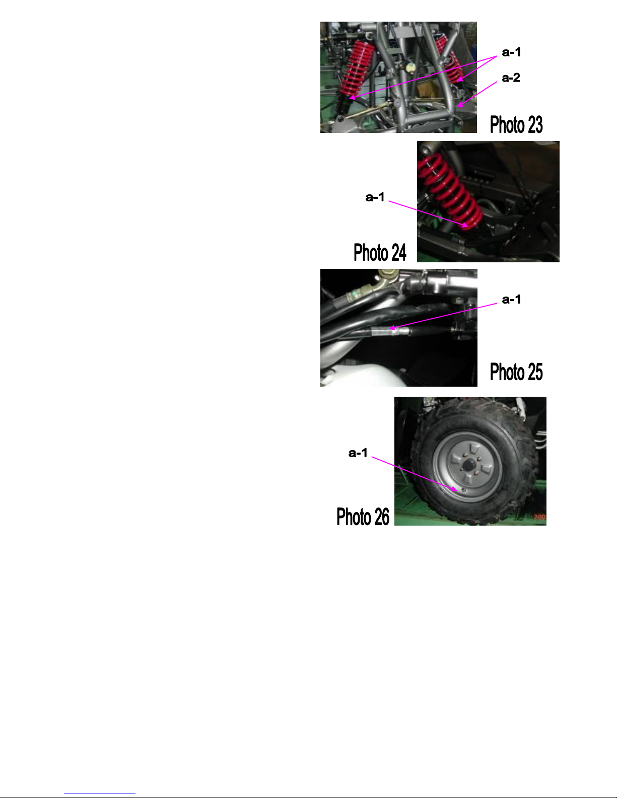
FRONT SUSPENSION
1. Check the R. and L. side suspension, the front
suspension should be adjusted to the same preload (a-1).
2. Inspect the shocks for oil leakage; if any is present,
replace shocks.
3. Check the welding of frame bracket, which is
connected to front suspension.
4. Also, check the swing arm for cracks or dents (a-2).
(Photo 23)
REAR SUSPENSION
1. Check the rear suspension for proper spring preload
(a-1). Inspect the shock for oil leakage; if any is present,
replace shock
2. Check the welding of frame bracket that connects
with rear shock and the condition of swing arm.
(Photo 24)
MANUAL CHOKE CABLE
There is an adjustment screw under the master cylinder
to control the amount of choke opening for proper
starting (a-1).
(Photo 25)
WHEELS AND TIRES
Inspect the tire surface for cuts, nails or other sharp
objects. (a-1).
Check the tire pressure at cold tire conditions.
The standard tire pressure is 3psi. (0.15kgf/cm2 )
(Photo 26)
15
FIG-02. Vehicle Inspection
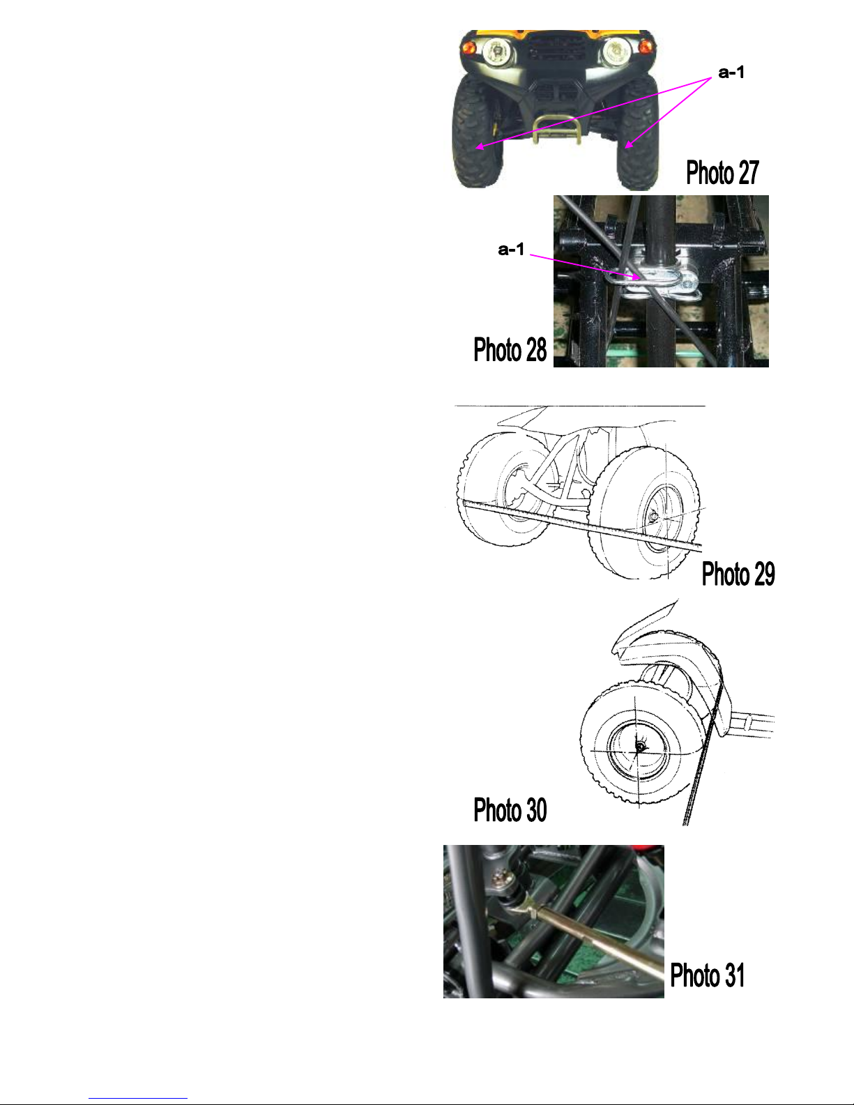
STEERING SYSTEM
Check the free play of the steering shaft with the front
wheels turned straight ahead. When there is excessive
play, inspect the tie-rod, kingpin bushing and ball joint.
(a-1).
(Photo 27)
STEERING SHAFT HOLDER BUSHING
Remove the front fender.
Remove the steering shaft holder and check the steering
shaft bushing for wear or damage.
If the bushing is worn or damaged, replace the bushing.
Grease the steering shaft bushing and install the parts in
the reverse order of removal. (a-1)
(Photo 28)
Torque: steering shaft holder bolt: 33N.m ( 24 Ft. lbs)
TOE-IN
Park the vehicle on level ground with the front wheels
facing straight ahead.
Mark the centers of the tires to indicate the axle center
height.
Measure the distance between the marks.
Carefully move the vehicle back, let the wheels turn
180° so the marks on the tires are aligned with the axle
center height.
(Photo 29)
Measure the distance between the marks.
Calculate the difference in the front and rear
measurements.
(Photo 30)
Toe-in: 5±10 mm
If the toe-in is out of standard, adjust it by changing the
length of the tie-rods equally by turning the tie-rod
while holding the ball joint.
Tighten the lock nuts (a-1)
Torque: 35-43 N.m
(Photo 31)
16
FIG-02. Vehicle Inspection
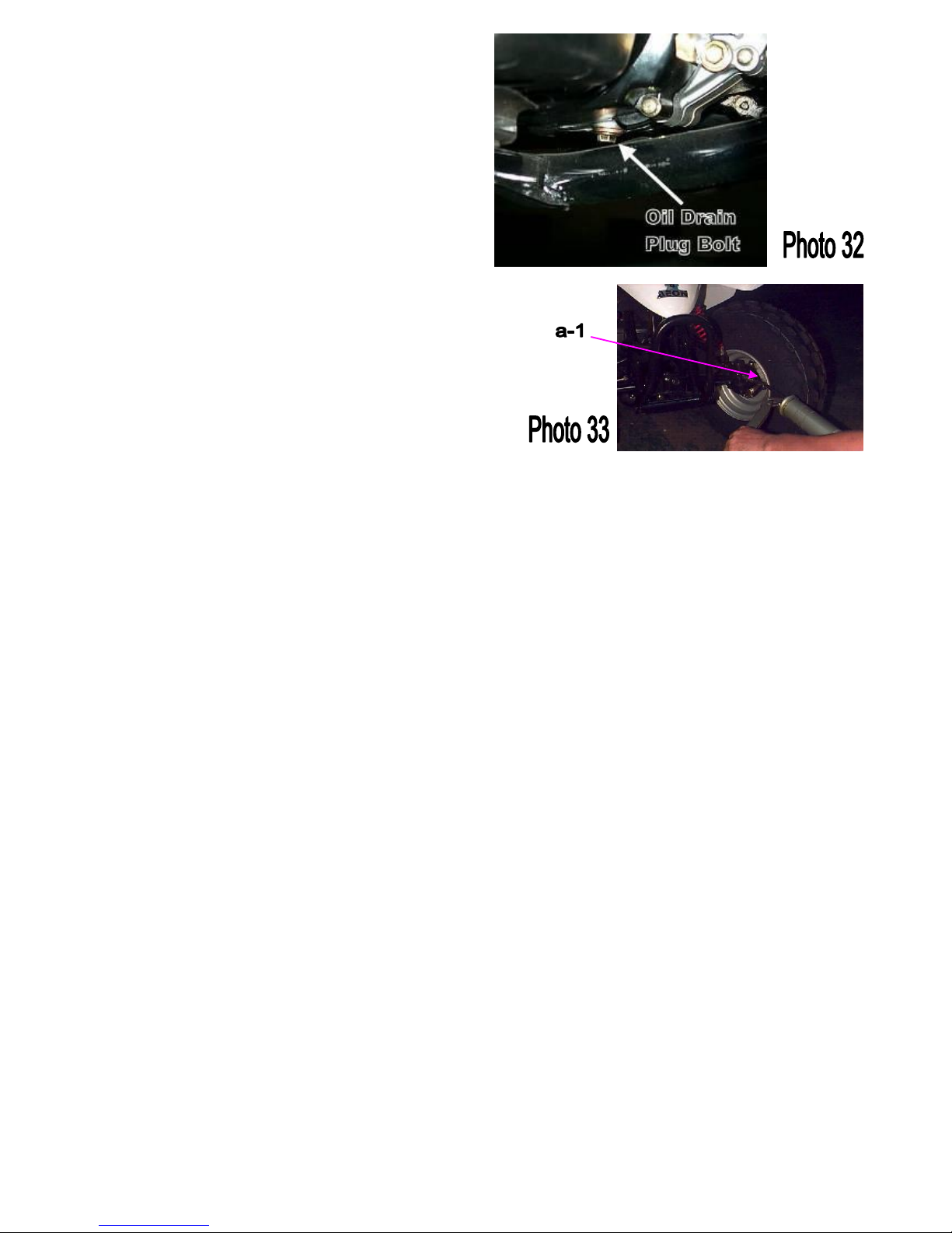
GEAR OIL MAINTENANCE
Gear oil needs to be changed every 200 hours.
There is a gear oil drain hole bolt at the rear of the
engine.
1. Unscrew this drain hole bolt and let the dirty oil flow
out, catching the oil in a proper container for later
disposal.
2. Reinstall the drain hole bolt and tighten.
3. Fill with new gear oil through the oil fill hole located
on the engine case beside the gearbox.
(Photo 32)
LUBRICATE
There is a grease valve on the R. and L. suspension arm
and swing arm sub ass’y (a-1).
Please lubricate the grease frequently on the grease
valve.
(Photo 33)

17
0.6~0.7
mm
18
FIG-03. Overview
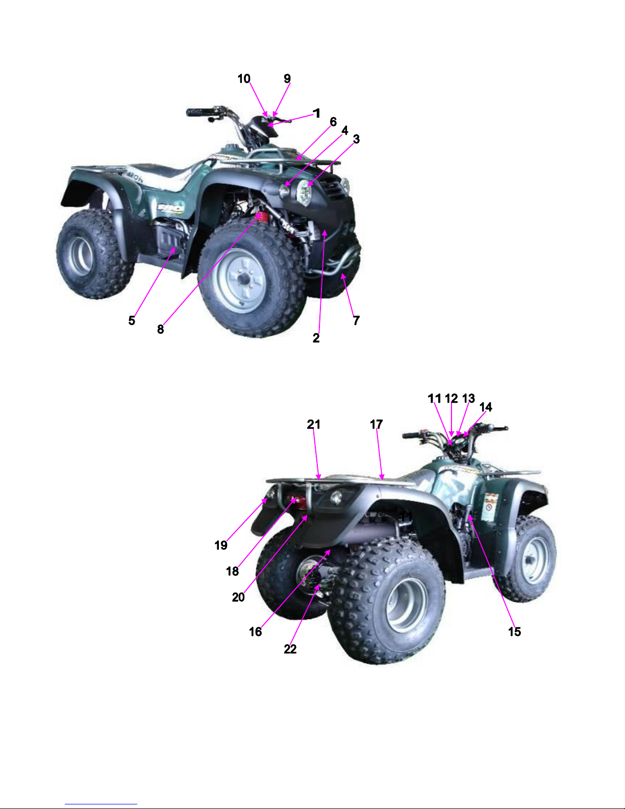
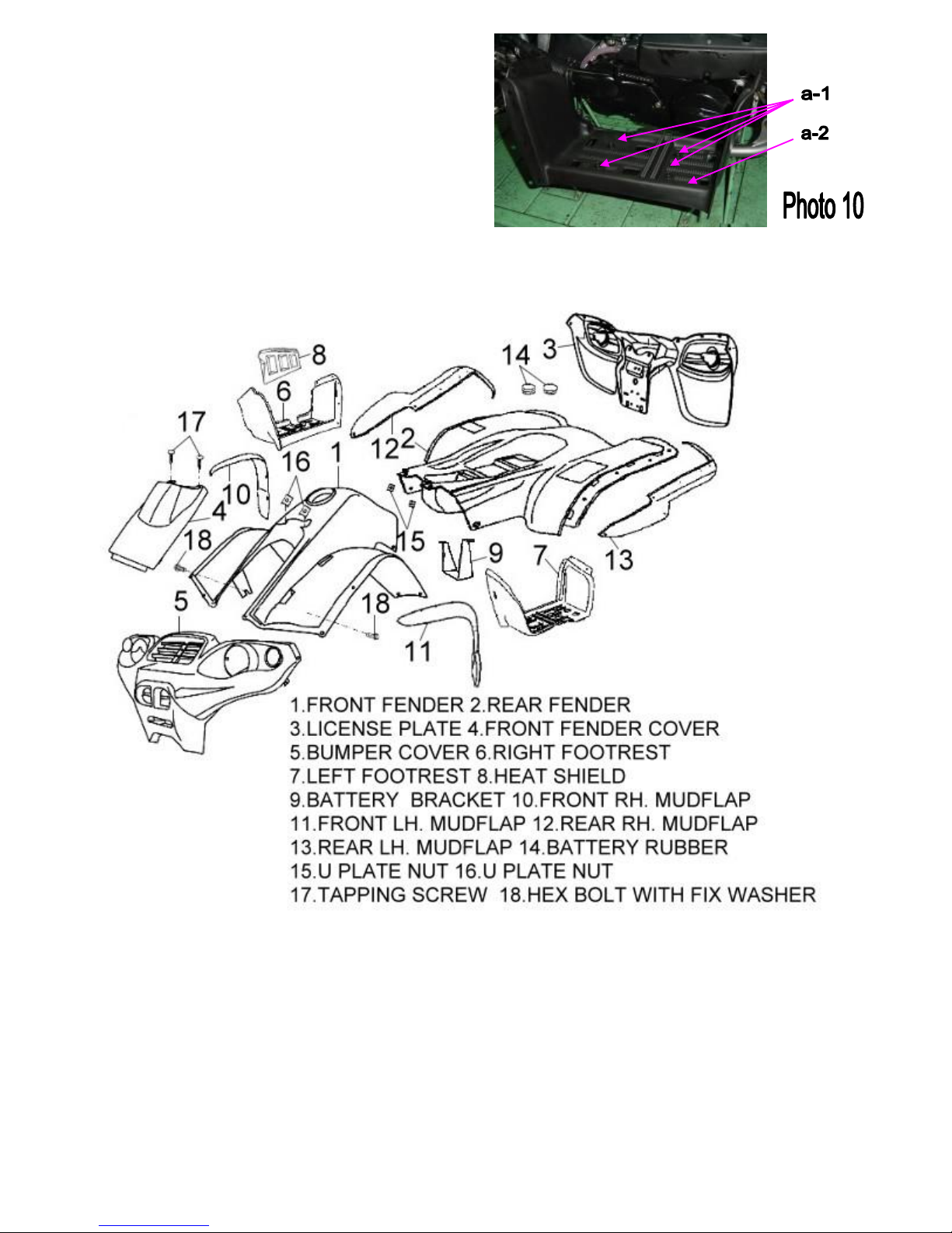
Parts Description
11. MAIN SWITCH ASS'Y
12. NEUTRAL INDICATOR
13. REVERSE INDICATOR
14. FUEL GAUGE ASS'Y
15. TRANSMISSION LEVER
16. REAR SUSPENSION
17. SEAT
18. TAIL LIGHT ASS’Y
19. REVERSE LIGHTS
20. REFLECTOR
21. REAR METAL RACK
22. TRAILER HITCH MOUNT
01. HANDLE BAR COVER
02. FRONT FENDER CARRIERS
03. HEAD LIGHT ASS’Y
04. POSITION LIGHT ASS’Y
05. MASTER CYLINDER SUB(L)
06. FRONT METAL RACK
07. BUMPER
08. FRONT SUSPENSION
09. RIGHT LEVER ASS'Y
(Including parking brake)
10. L. SWITCH ASS'Y
19
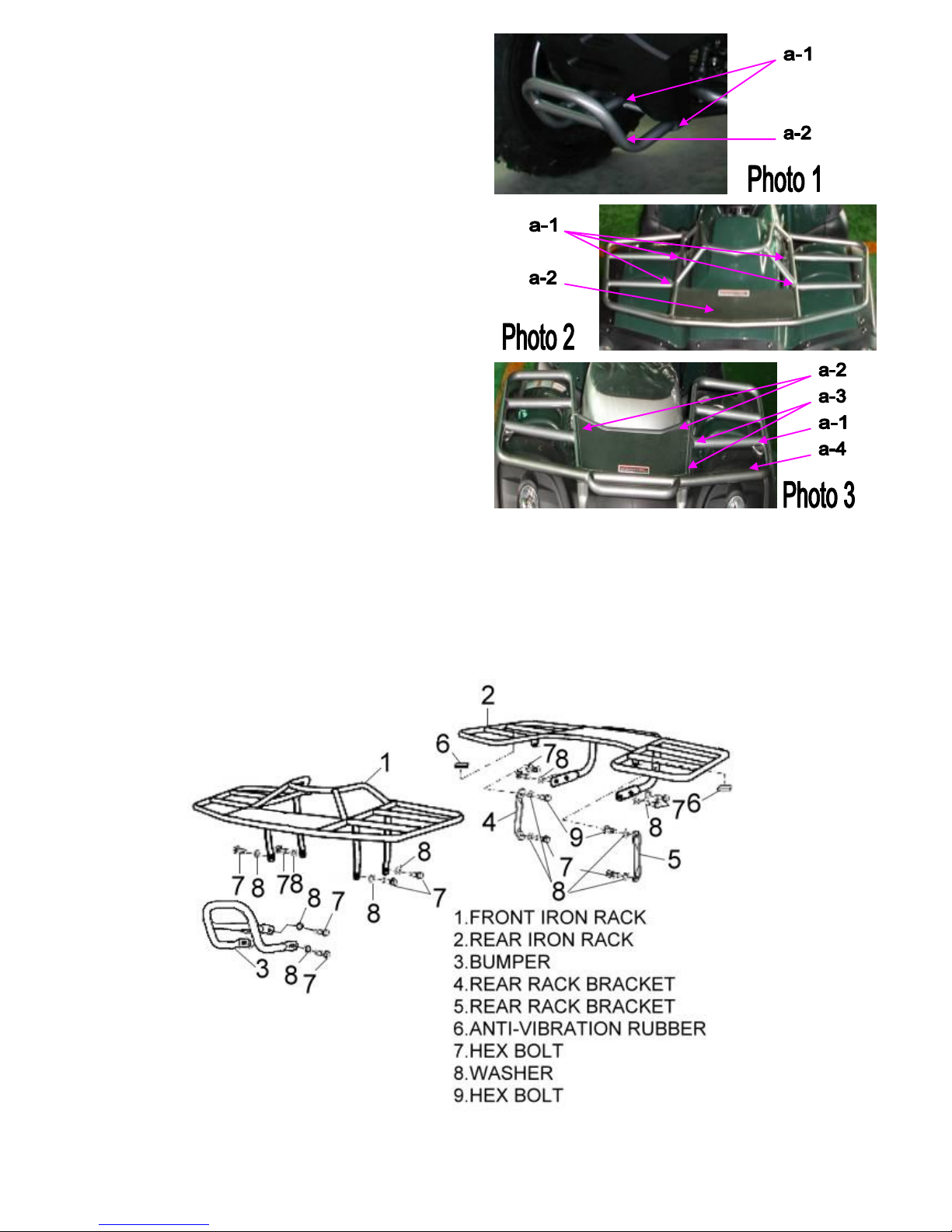
FIG-04. Fender
BUMPER
Loosen the bolts (a-1) and Remove the bumper (a-2)
from the frame body
(Photo 1)
FRONT METAL RACK
Loosen the bolts (a-1)
and Remove the front metal rack (a-2)
from the frame body
(Photo 2)
REAR METAL RACK
Loosen the screws (a-1)
Loosen the bolts (a-3)
Remove the rear rack bracket (a-2)
Loosen the bolts (a-3)
Remove the rear metal rack (a-4)
(Photo 3)
Note:
Refer to the preceding disassembly instructions for
re-assembly.
20
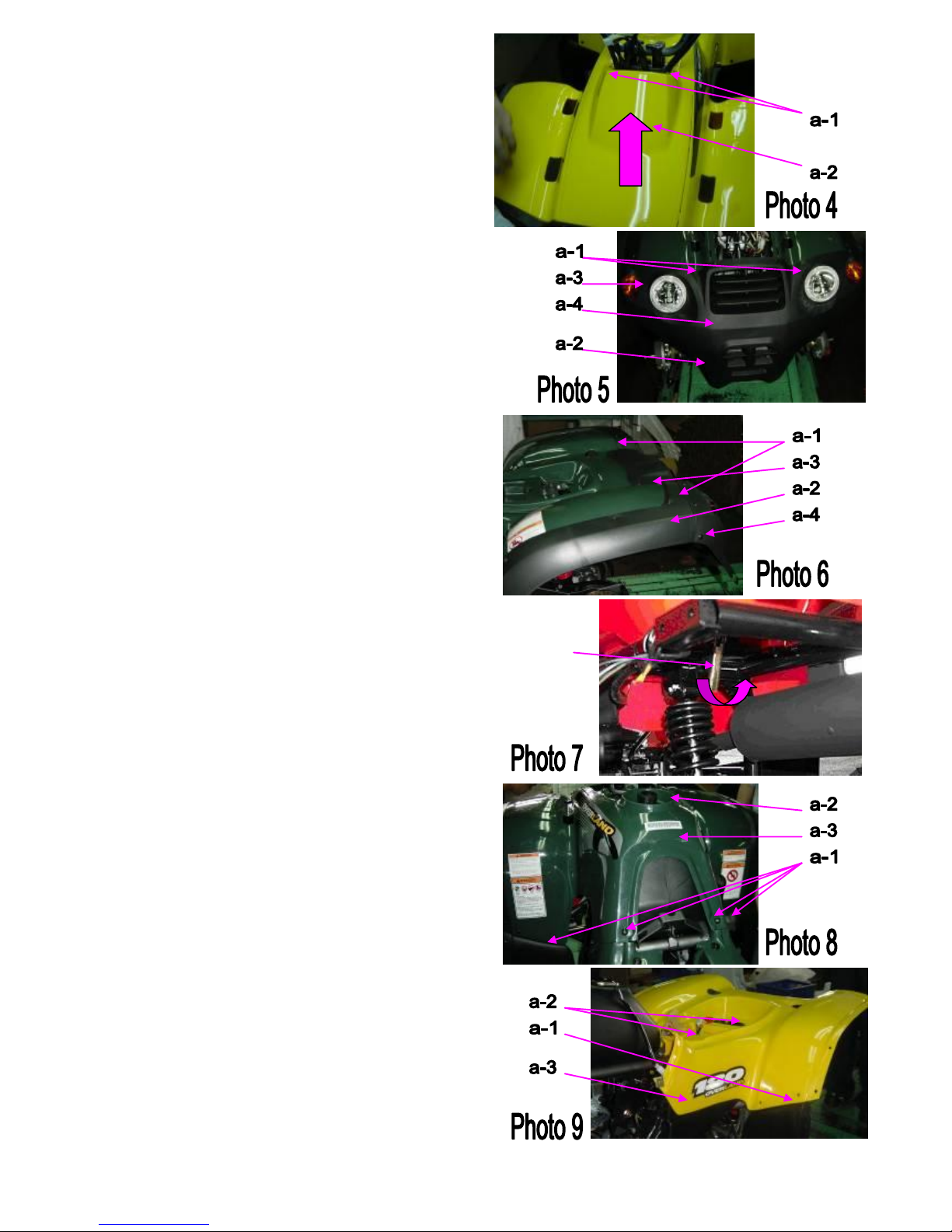
FIG-04. Fender
FRONT FENDER COVER
Loosen the screws (a-1)
Remove the front fender cover (a-2)
(Photo 4)
BUMPER COVER
Loosen the screws (a-1)
Loosen the screws (a-2)
Take off the main wire connect with the lights wire (a-3)
Remove the front fender cover (a-4)
(Photo 5)
LICENSE PLATE
Loosen the screws (a-1)
Loosen the screws (a-2)
Take off the main wire connect with the lights wire (a-3)
Remove the license plate (a-4)
(Photo 6)
SEAT ASS'Y
Pull the “Seat Release Bar” to take off the seat. (a-1)
This seat release bar is under the right side of the rear
fender. Remove the seat ass’y
(Photo 7)
FRONT FENDER
Loosen the screws (a-1)
Loosen the hex bolt with plain washer (a-2)
Take off the fuel tank cap
Remove the front fender (a-4)
(Photo 8)
FRONT FENDER
Loosen the screws (a-1)
Loosen the hex bolt with plain washer (a-2)
Remove the front fender (a-3)
(Photo 8)
CAUTION
1. The battery and the toolbox are put under the seat.
21
FIG-04. Fender
FOOTREST
Loosen the bolts (a-1)
Remove the footrest ass’y (a-2)
(Photo 10)
Note:
Refer to the preceding disassembly instructions for
re-assembly.
22
FIG-05. Fuel & Oil Tank
FUEL TANK
Loosen the bolts (a-1)
Take off the main wire connect with the fuel gauge wire
(a-2)
Loosen the bolts (a-3)
Remove the petcock ass’y, vacuum shut-off (a-4)
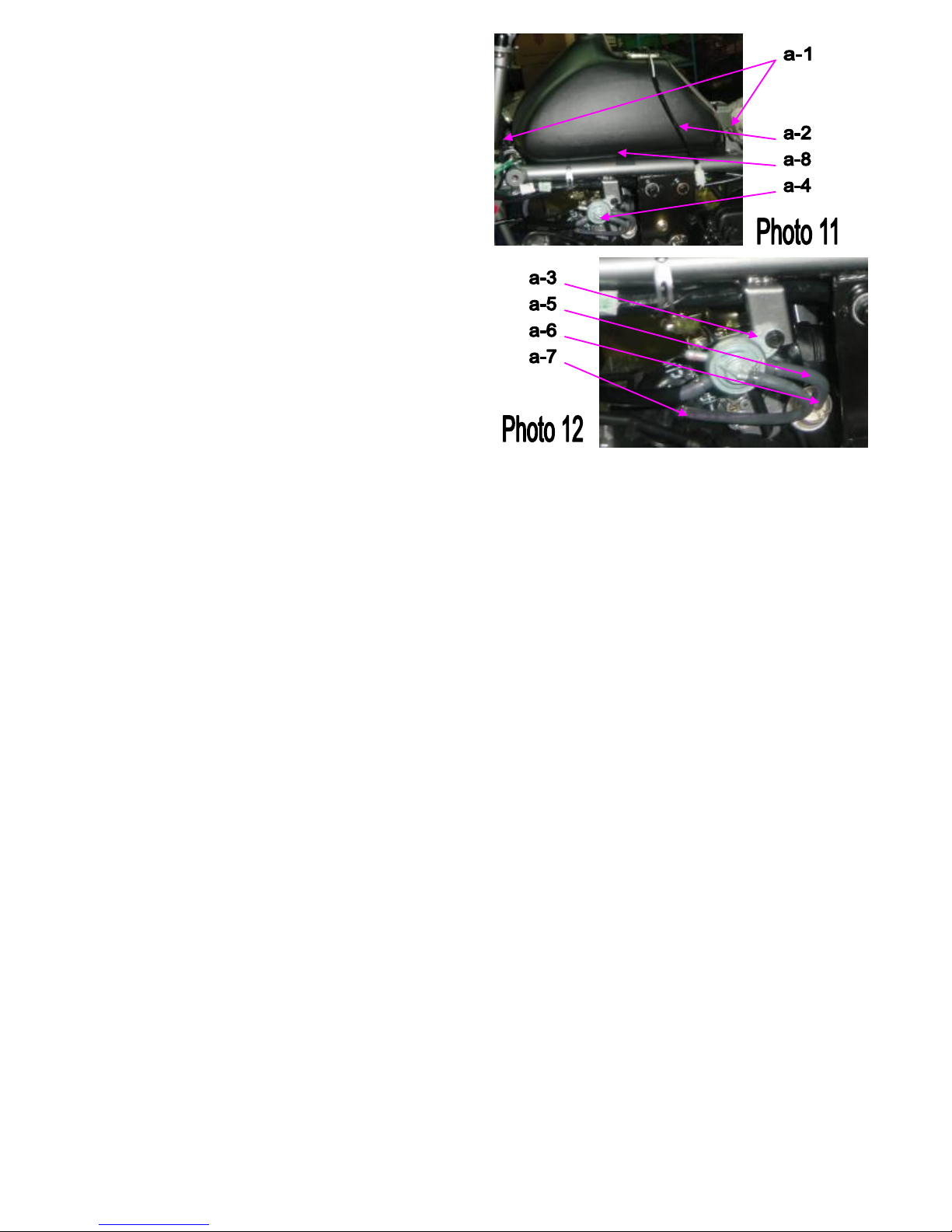
Remove the fuel tube (a-5) with the fuel filter ass’y(a-6)
Remove the air tube (a-7)
Remove the fuel tank (a-8) leave the frame body
(Photo 11,12)
CAUTION
1. There are rubbers on the frame body to reduce the
vibration and to protect the fuel tank.
2. There is a breather tube in the fuel cap.
Note:
Refer to the preceding disassembly instructions for
re-assembly.
23
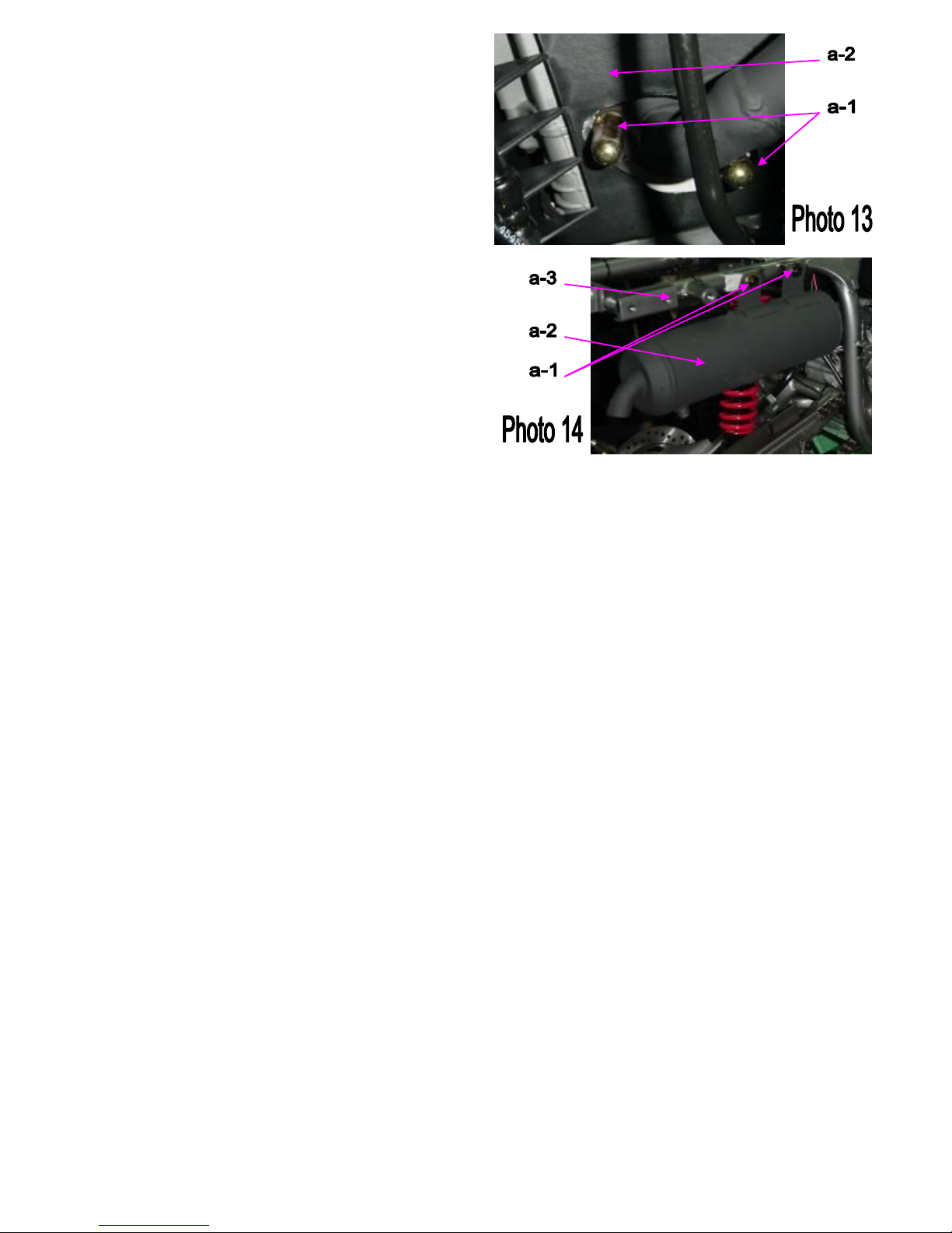
FIG-06. Muffler
MUFFLER
Loosen the bolts (a-1) and make it connected to the
cylinder (a-2).
(Photo 13)
CAUTION
1. The muffler is hot during operation.
2. Do not touch the muffler or the heat shields.
3. Please check the gasket of muffler before mounting
the muffler.
Loosen the bolts (a-1) of the muffler (a-2)
on the frame body (a-3).
(Photo 14)
Note:
Refer to the preceding disassembly instructions for
re-assembly.
24
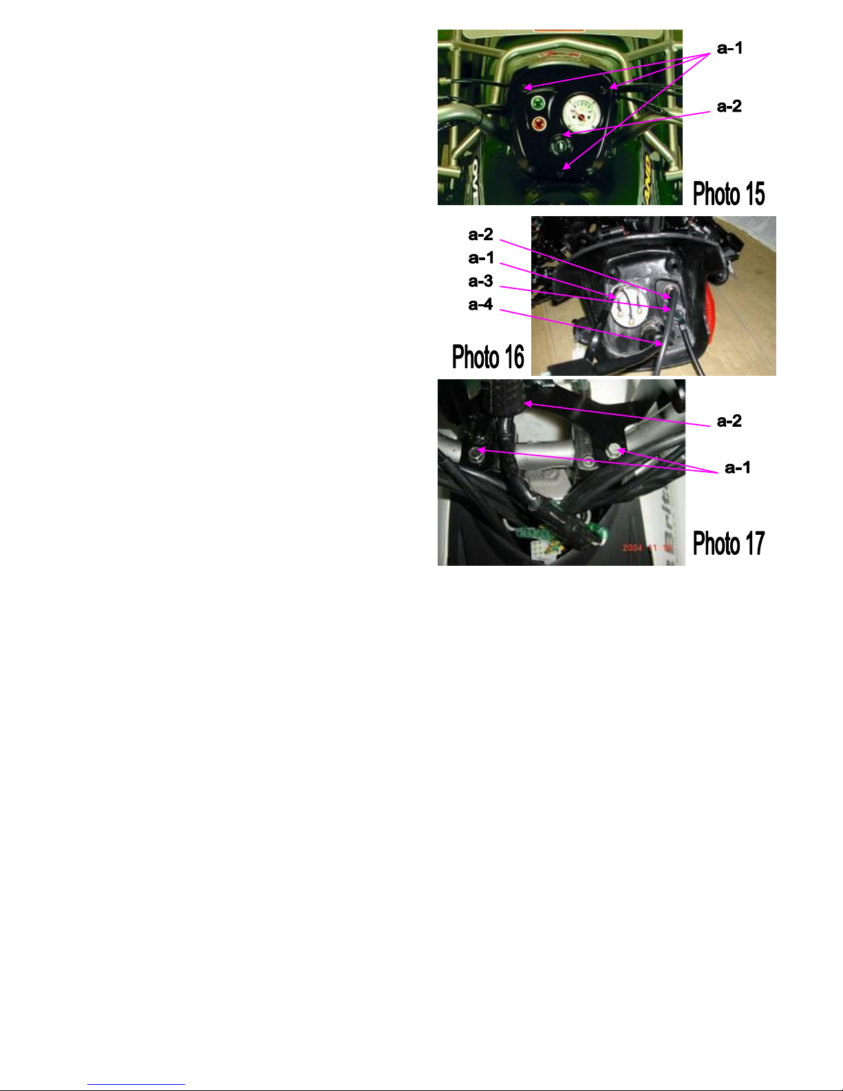
FIG-07. HANDLEBAR
HANDLE BAR COVER
Loosen the screws (a-1)
Remove the head light cover (a-2)
Take off the main wire connect with the head light wire
(Photo 15)
Remove the fuel gauge ass’y (a-1)
Loosen the nut remove the neutral indicator (a-2)
Loosen the nut remove the reverse indicator (a-3)
Remove the main switch clip and take off the main
switch (a-4)
(Photo 16)
Loosen the bolts (a-1)
Remove the protect cover mounting plate (a-2)
(Photo 17)
25
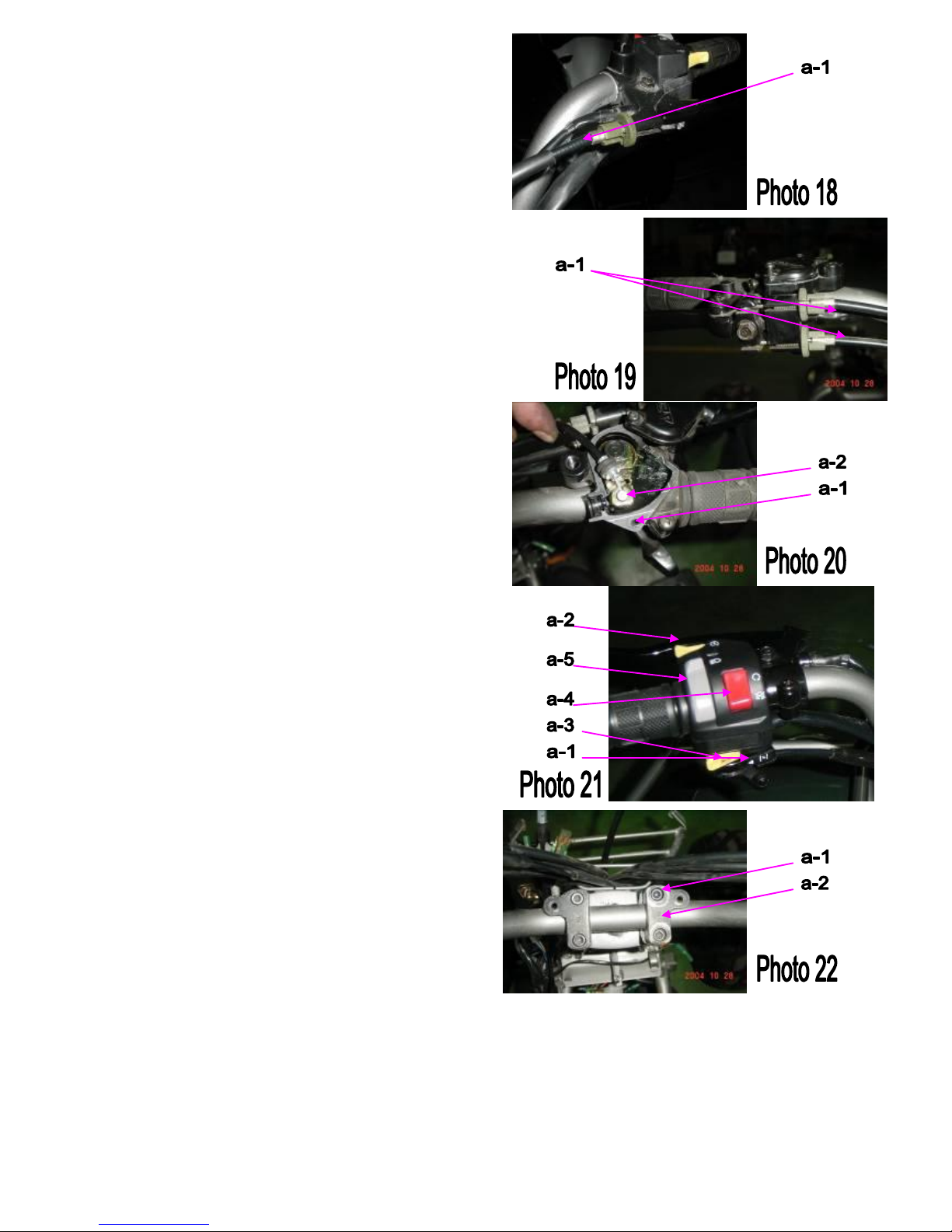
FIG-07. HANDLEBAR
REAR BRAKE CABLE
Remove the rear brake cable (a-1)
(Photo 18)
FRONT BRAKE CABLE
Remove the R. and L. front brake cable (a-1)
(Photo 19)
THROTTLE CABLE
Right lever ass’y loosen the screws (a-1)
open the cover and mount the throttle cable (a-2)
in the box
(Photo 20)
CAUTION
1. Smear grease on the throttle wire before mounting it
in the throttle box.
2. There is a park brake on the R. level.
3. It is design for safety assurance. When the vehicle
stopped on the slope ground, please operate the park
brake.
MANUAL CHOKE WIRE
Remove the manual choke wire on the L. Switch (a-1)
(Photo 21)
The L. Switch includes the engine start switch (a-2),
Horn switch (a-3)
Engine stop switch (a-4),
Headlight (high/low beam) switch (a-5).
(Photo 21)
HANDLE BAR CLAMP COVER
Loosen the bolts (a-1)
Remove the handle bar ass’y (a-2)
(Photo 22)
Note:
Refer to the preceding disassembly instructions for
re-assembly.
 Loading...