

Kolpin 86400 User Manual
86400 – UTV Plow
CORPORATE HEADQUARTERS
Kolpin Powersports, Inc.
P.O. Box 107, 205 N. Depot Street
Fox Lake, Wisconsin 53933-0107
Telephone: (920) 928-6514
Toll Free: (877) 956-5746
Fax: (920) 928-6440
Series
Customer Service:
E-mail: customerservice@kolpinpowersports.com
Customer Service: (920) 928-6514, Option 1
Customer Service Fax: (920) 928-3782
1

86400 – UTV 72” Snow Plow
Part Description Size Qty.
1 Plow Lift Assembly Metal component 1
2 Extra Plates Metal component 2
3 Bolt ½”-13 x 2-1/2” 8
4 Washer ½” 8
5 Nylock Nut ½”-13 8
6 Chain Lift Arm Metal component 1
7 Bolt 5/8” x 3-1/2” 1
8 Flat Washer 5/8” x 5mm (Black) 4
9 Nylock Nut 5/8” 1
10 Pivot Pin (Actuator Location) ½” x 60mm 2
11 “R” Clip (actuator Location) Hardware 2
12 Bent Hitch Pin 5/8” x 3” 2
13 “R” Clip (Down Pressure Turnbuckle) Hardware 2
14 PTO Locking Pin 3/8” x 2-1/4” 1
15 Lift Chain 775mm long 1
16 Top Link with clevis Hardware 1
17 Main Hitch Tube Metal component 1
18 Bolts 5/8” x 3-1/2”“ 2
19 Flat Washer 5/8” 2
20 Nylock Nut 5/8” 2
21 Bent Hitch Pin (to secure at receiver hitch) 5/8” x 3” 1
22 “R” Clip (to secure at receiver hitch) Hardware 3
23 Blade Height Frame Metal component 1
24 Bent Hitch Pin (to secure at receiver hitch) 5/8” x 3” 2
25 “R” Clip (to secure at receiver hitch) Hardware 2
26 Main Blade Support Frame Metal Component 1
28 Washer (Large Black Painted Washer Metal Component 1
33 Spring (pivot stop pin location) 3/8” x 1.5” 1
34 Pivot Stop Pin 3/8” – 5/8” x 3.25” 1
35 Nylock Nut 3/8” 1
36 Blade Pivot Assembly Metal Component 1
37 Blade Pivot Stop Plates (Black Painted) Metal Component 2
38 Bolt 3/8” x 1-1/2” 2
39 Washer 3/8” 2
40 Nylock Nut 3/8” 2
41 Pivot Pin (Dirt Blade Stop Pin) ½” x 60mm 2
70 “R” Clip (Dirt Blade Stop Pin) Hardware 2
42 Bolt (Blade Pivot) 5/8” x 1-1/2” 2
43 Flat Washer 5/8” 2
44 Nylock Nut 5/8” 2
45 Bolt (Main Blade Pivot) ¾” x 2” 1
46 Flat Washer ¾” 1
47 Nylock Nut ¾” 1
48 Main Blade Assembly Metal Component 1
51 Cutting Edge (Black Painted) ¼” x 4” x 72” 1
52 Carriage Bolt 5/16” x 1.25” 11
53 Flat Washer 5/16” 11
54 Nylock Nut 5/16” 11
55 Wire Harness (Toggle style) 144” 1
56 Electric Lift Actuator 1
57 Assembly Manual – Part List 1
61 Trip Springs 7/8” x 6” 4
62 “I” Bolt 5/16” x 6” 4
63 Hex Nut 5/16” 4
64 Nylock Nut 5/16” 4
65 Skid Plate (Black Painted) Metal Component 2
66 “R” Clip ½” x 2” 2
67 ¾” Flat Washer ¾” - 24
72 Winch Roller 1.5” x 1.625” x 6.5” 1
69 Plastic Cap 2” x 2” 1
71 Removable Link 3/16” x 2” Removable Chain Link 1
Please verify all components are included in the shipping container before proceeding.
2
Rev 4.0 – 4/23/07
Important!
Please read through the entire instruction manual once before proceeding.
Tools Required:
Before you start:
Make sure the area you are working is clean and clear of any dirt or debris that might hinder the assembly of
your DirtWorks Disk Plow Implement.
Assembly Steps:
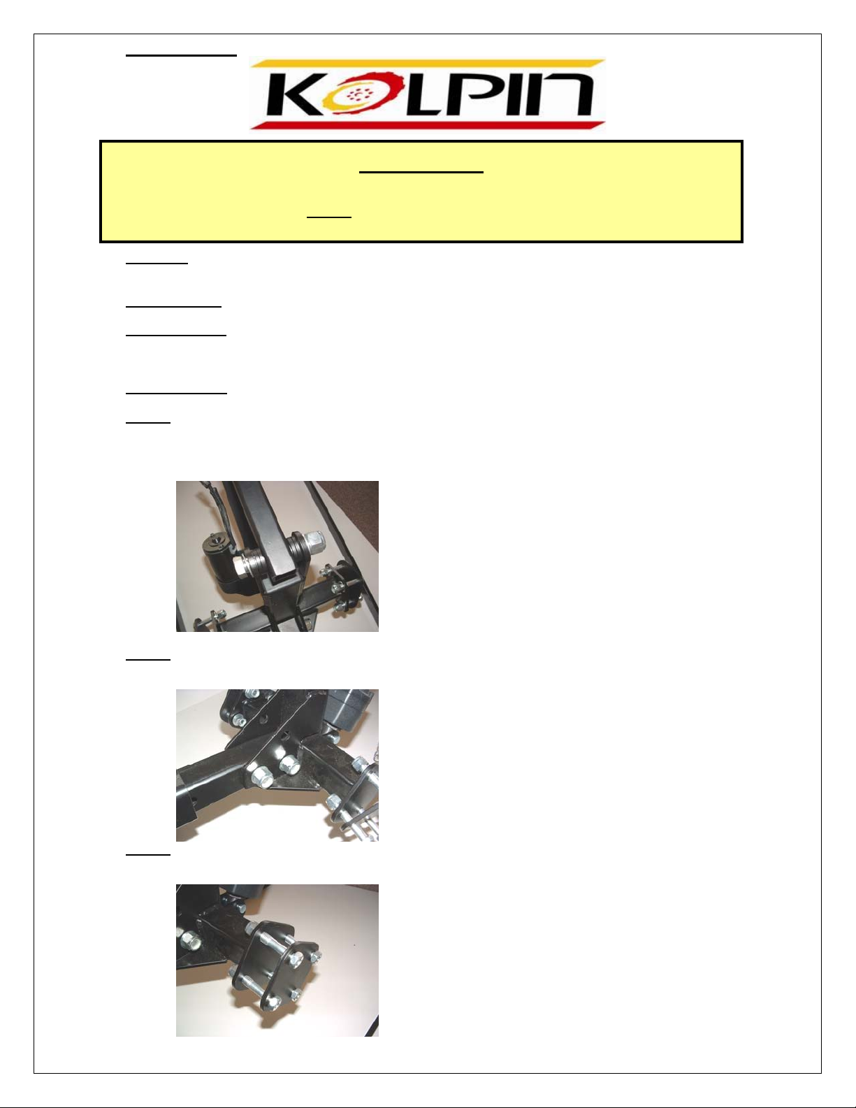
Step #1
1. Locate #1, 2, 3, 4, 5, 6, 7 and 8 items from parts list.
2. Secure #6 between upper two vertical metal posts on #1 with as shown in Picture. Place (2) 5/8”
Never exceed 5mph while using the DirtWorks UTV Plow.
Adjustable Wrench Set and Socket Set.
Black Painted Washers #4 on either side of #6 during assembly. Secure outside washer and nylock
nut. You do not need to over tighten this.
CAUTION!!!
Step #2
Step #3
1. Secure Main Hitch Tube #17 to #1 assembly at this time using #18, 19, 20 hardware.
2. Tighten all hardware at this location.
1. Locate (2) #2 Extra Plates and qty (8) each of Hardware #3, 4 and 5.
2. Secure Plates in place with hardware but do not tighten at this time.
3
 Loading...