

Kolpin 20053 User Manual
NO.
Description
QTY.
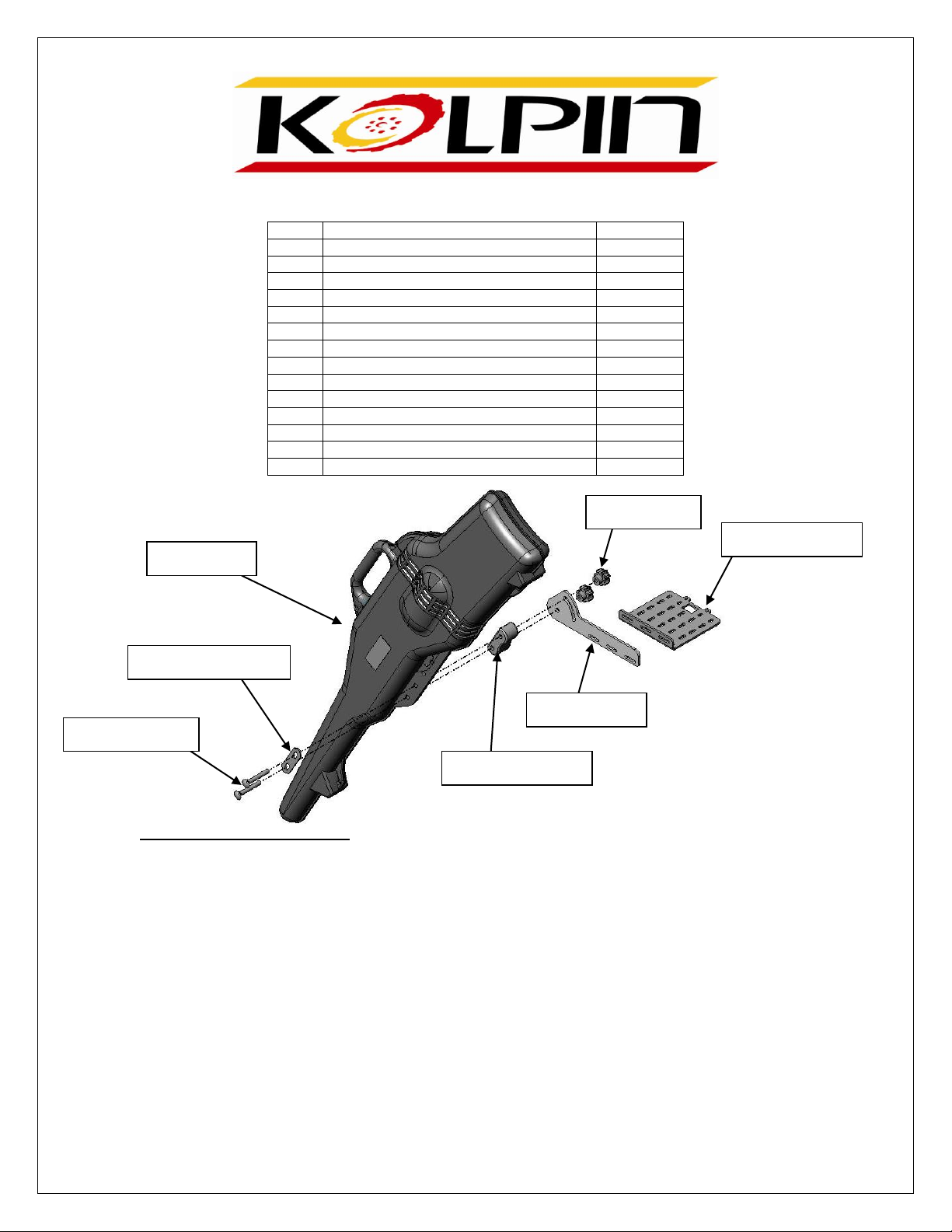
1
Gun Boot
1
2
Mounting Plate
1
3
Swivel Plate
1
4
Support Bracket
1
5
Rubber Bushing
1
6
3/8” Carriage Bolt
2
7
3/8” Turn Knob
2
8
3/8” Washers
2
9
¼” – 20 U-Bolt
3
10
¼” x ¾” Truss Head Bolt
2
11
¼” - 20 Nylock Nut
8
12
¼” Washer
10
13
Pin Lock
1
14
Rubber Caps
6
Carriage Bolt
Rubber Bushing
Swivel Plate
Turn Knob
Mounting Plate
Gun Boot
Support Bracket
Rev. 2
20053 – KOLPIN GUN BOOT 4.3
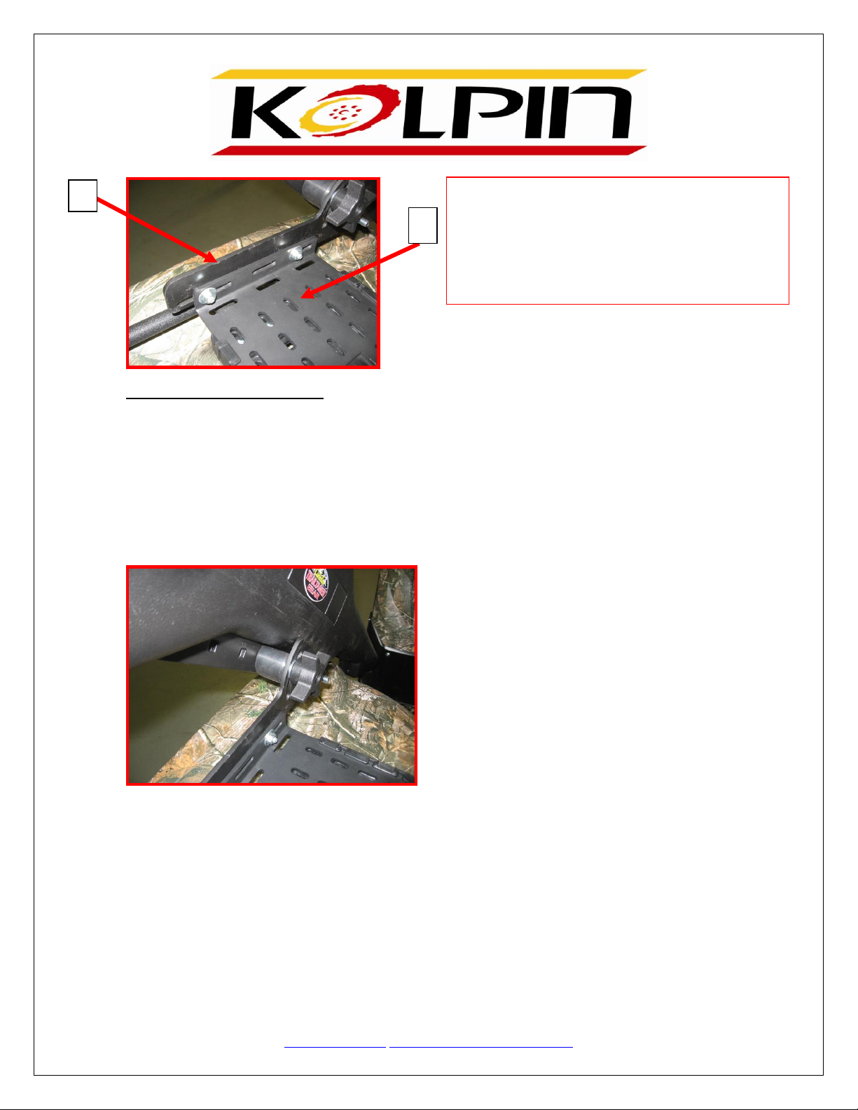
Bracket Assembly Instructions:
1. Attach the Swivel Plate (#2) to the Mounting Plate (#3) (as shown below) to best accommodate your
ATV, using (2) ¼” x ¾” Truss Head Bolt and (2) ¼” Washers and Nylock Nuts. Slots are provided for
individual fitment to each machine.
2. Attach the Mounting Plate to your ATV using (3) ¼” – 20 U-Bolts, under the rack and up through the
Mounting Plate and secure using the (6) ¼” Nylock Nuts and (6) Washers. Tighten Securely. Place the
Rubber Caps over the protruding threads of the U-Bolt.
Rev. 2
2
FYI: The Gear Lock and Load Plate (Sold Separately) is
made to accept the Metal Mounting Plate. Simply slide
the Mounting Plate into the slots of the Gear Lock and
Load until you hear it snap. The snap is made by the
square hole in the Metal Mounting Plate engaging the tab
on the Gear Lock and Load. To remove, press the tab on
Gear Lock and Load and slide out the entire Gun Boot
Bracket.
3
Gun Boot Mounting Instructions:
1. To attach the Gun Boot to the Bracket, use the (2) 3/8” Carriage Bolts through the Support Bracket, then
the Gun Boot and finally through the Rubber Bushing. Be sure that the Rubber Bushing has the flat side up
towards the bottom of the Gun Boot.
2. Now place the Carriage Bolts through the single hole and slot on the Swivel Plate as pictured above in
the exploded view. Secure the carriage bolt with (2) 3/8” Turn Knobs and 3/8” Washers provided. Tighten
Securely. The knobs allow you to adjust your Gun Boot angle, or remove your Gun Boot without any tools if
necessary.
NOTE: BRACKET CAN BE USED ON EITHER SIDE OF THE ATV.
205 N. Depot Street, Fox Lake, WI 53933
Phone #: (877) 9KOLPIN or (920) 928-3118
www.kolpin.com customerservice@kolpin.com
Kolpin Outdoors, Inc.
 Loading...