

Page 1

AKM
English Instructions Manual
Deutsch Betriebsanleitung
Italiano Manuale di Istruzioni
Español Manual de Instrucciones
Français Manuel d'Installation
Русский Руководство по эксплуатации
Edition June 2018
European Version (CE region)
English Deutsch Italiano Español Français Русский
Original Languageis English. All other content is translated from the original language.
Keep allmanuals asa product component during the life
span of the product. Passall manualsto future users and
owners of the product.
Conserve el manual durante toda la vida útildel producto.
Entregue el manual a posteriores usuarioso propietarios del
producto.
Сохраняйте все руководства как составную часть
продукта в течение всего срока его эксплуатации.
Передавайте руководство следующему пользователю
или владельцупродукта.
Bewahren Siealle Anleitungen während der gesamten Nutzungsdauer
des Produkts alsProduktkomponente auf. Händigen Sie alle Anleitungen künftigen Anwendern/Besitzern des Produkts aus.
Conservare il manuale per l’intera durata del prodotto. In caso dicambio di proprietà il manuale deveessere fornito al nuovo utilizzatore
quale parte integrante del prodotto.
Le manuel faisant partie intégrante du produit, conservez-le pendant
toute la durée de vie du produit. Remettez lemanuel au futur utilisateur
ou propriétaire du produit.
Page 2

Record of Document Revisions
Revision Remarks
... Table with lifecycle information of this document (➜ # 209)
11/2017 Connector options G, H updated, Low Voltage windings added, corrected value B
brake, note about B
andnumber of springs, AKM82T resistance updated, Web pages updated
10d
01/2018 Number of springs updated
06/2018 Thermal sensor KTY 83-110 replaced by PT1000, Pin-outs updated
Table of Contents
Instructions Manual
Betriebsanleitung
Manuale di Istruzioni
Manual de Instrucciones
Manuel d'Installation
Руководство по эксплуатации
English
Deutsch
Italiano
Español
Français
Русский
(➜ # 3)
(➜ # 29)
(➜ # 55)
(➜ # 83)
(➜ # 111)
(➜ # 139)
Technical Data (➜ # 167)
DimensionDrawings (➜ # 186)
Connector Pinout (➜ # 200)
Approvals (➜ # 207)
Trademarks
l EnDat is a registered trademark of Dr. Johannes Heidenhain GmbH
l HIPERFACE is a registered trademark of Max Stegmann GmbH
l HIPERFACE DSL® is registered trademark of SICK STEGMANN GmbH.
l DRIVE-CLiQ and SIMATIC are registered trademarks of SIEMENS Aktiengesellschaft
for AKM4
10d
Technische Änderungen, die der Verbesserung der Geräte dienen, vorbehalten!
Gedruckt in der BRD. Alle Rechte vorbehalten. Kein Teil des Werkes darf in irgendeiner Form (Fotokopie, Mikrofilm
oder in einem anderen Verfahren) ohne schriftliche Genehmigung der Firma Kollmorgen Europe GmbH reproduziert
oder unter Verwendung elektronischer Systeme verarbeitet, vervielfältigt oder verbreitet werden.
Technical changes to improve the performance of the equipment may be made without prior notice!
Printed in the Federal Republic of Germany. All rights reserved. No part of this work may be reproduced in any form
(by photocopying, microfilm or any other method) or stored, processed, copied or distributed by electronic means
without the written permission of Kollmorgen Europe GmbH.
Il produttore si riserva la facoltà di apportare modifiche tecniche volte al miglioramento degli apparecchi
Stampato nella Repubblica federale tedesca. Tutti i diritti riservati. Nessuna parte di questo documento può essere
rielaborata, riprodotta in qualsiasi forma (fotocopia, microfilm o altro processo) o diffusa mediante l'uso di sistemi
elettronici senza l'approvazione scritta della ditta Kollmorgen Europe GmbH o rielaborata, riprodotta o diffusa mediante l’uso di sistemi elettronici.
Reservado el derecho de introducir modificaciones técnicas para la mejora de los equipos
Impreso en la RFA. Reservados todos los derechos. Prohibida la reproducción total o parcial de la presente obra por
cualquier medio (fotocopia, microfilm u otros), así como su procesamiento, reproducción y divulgación por medio de
sistemas electrónicos, sin expresa autorización escrita de la empresa Kollmorgen Europe GmbH.
Toutes modifications techniques concourant pour l'amélioration des appareils réservées !
Imprimé en Allemagne. Tous droits réservés. Aucune partie de l'ouvrage ne peut être reproduite sous quelque forme
que ce soit (imprimée, photocopiée, microfilmée ou par un autre procédé) ou encore traitée, reproduite ou diffusée
au moyen de systèmes électroniques sans autorisation écrite préalable de Kollmorgen Europe GmbH.
Сохраняется право вносить технические изменения, служащие для совершенствования устройств!
Напечатано в ФРГ. Все права защищены. Без письменного согласия фирмы Kollmorgen Europe GmbH
запрещается воспроизводить какие бы то ни было части данного руководства в любой форме (в печатной, в
виде фотокопии, микрофильма или другим способом), а также обрабатывать, размножать или распространять
их с использованием электронных систем.
2 Kollmorgen | kdn.kollmorgen.com | June 2018
Page 3

AKM Installation | 1 English
1 English
1.1 General 4
1.1.1 About this manual 4
1.1.2 Abbreviations used 4
1.1.3 Symbols Used 4
1.2 Safety 5
1.2.1 You should pay attention to this 5
1.2.2 Use as directed 7
1.2.3 Prohibited use 7
1.2.4 Handling 8
1.3 Package 10
1.3.1 Delivery package 10
1.3.2 Nameplate 10
1.3.3 Model number description 11
1.4 Technical Description 15
1.4.1 General technical data 15
1.4.2 Style 15
1.4.3 Flange 15
1.4.4 Protection class 15
1.4.5 Insulation material class 16
1.4.6 Surface 16
1.4.7 Shaft end, A-side 16
1.4.8 Shaft seal 16
1.4.9 Protective device 16
1.4.10 Vibration class 17
1.4.11 Wiring technology 17
1.4.12 Holding brake 18
1.4.13 Fanfor AKM7 18
1.4.14 Washdown and Washdown Food 19
1.5 Mechanical Installation 22
1.5.1 Important Notes 22
1.6 Electrical Installation 23
1.6.1 Important notes 23
1.6.2 Guide for electrical installation 24
1.6.3 Connection of the motors with preassembledcables 24
1.7 Setup 25
1.7.1 Important notes 25
1.7.2 Guide for setup 26
1.7.3 Trouble Shooting 27
1.8 Definition of Terms for Technical Data 28
Kollmorgen | kdn.kollmorgen.com | June 2018 3
Page 4

AKM Installation | 1 English
1.1 General
1.1.1 About this manual
This manual describes the adjust in target series of synchronous servomotors (standard version). The motors are operated in drive systems together with Kollmorgenservo amplifiers.
Please observe the entire system documentation, consisting of:
l Instructions manual for the servo amplifier
l Manual Bus Communication(e.g. CANopen or EtherCAT)
l Online help of the amplifier's setup software
l Regional accessories manual
l Technical description of the AKM series of motors
More backgroundinformation can be found on the Kollmorgen Developer Network, available
at kdn.kollmorgen.com.
1.1.2 Abbreviations used
Abbreviations used for technical data see chapter "Definition of terms" (➜ # 28).
In this document, the symbolism (➜ # 53) means: see page 53.
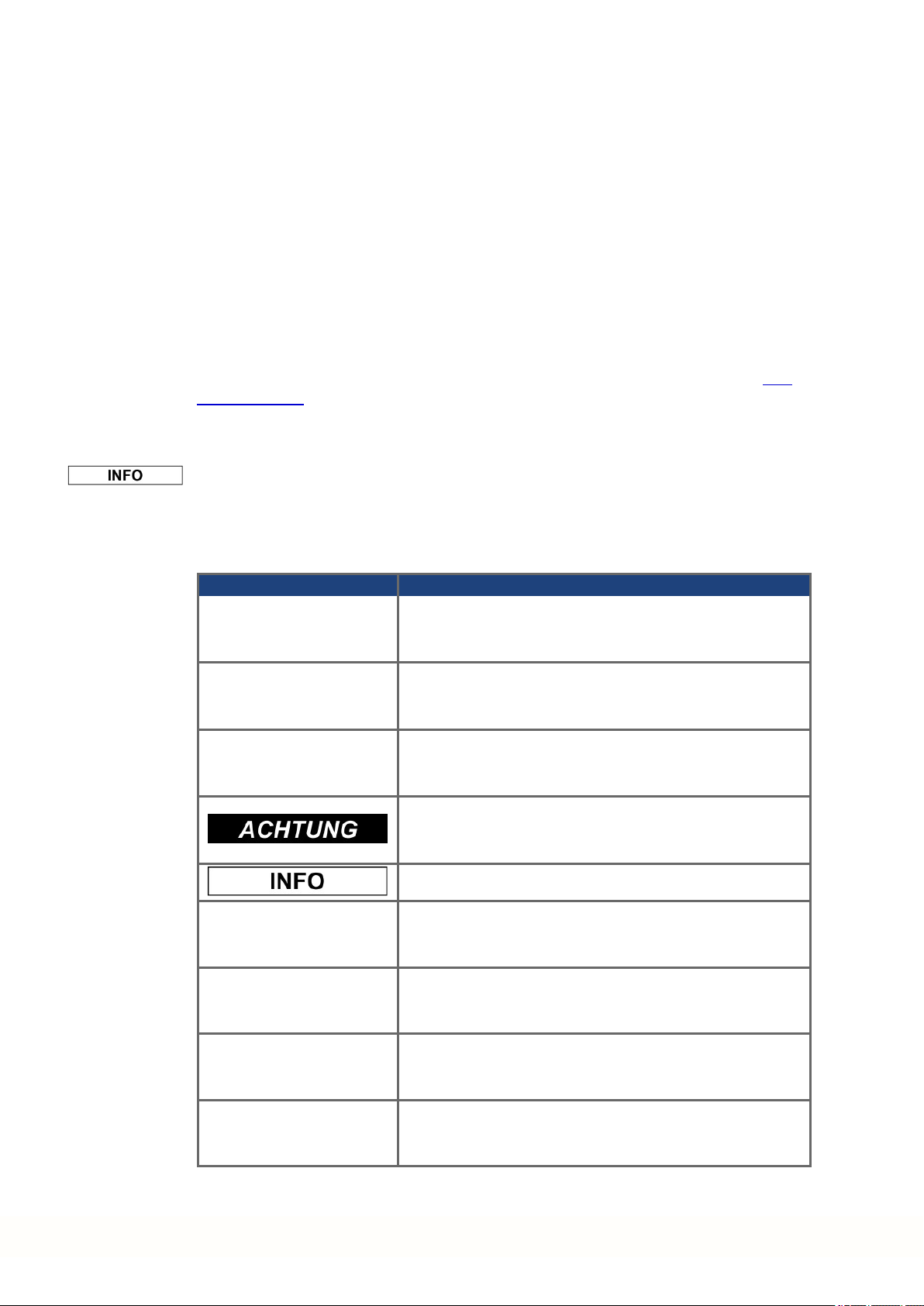
1.1.3 Symbols Used
Symbol Indication
DANGER
WARNING
CAUTION
Indicates a hazardous situationwhich, if not avoided, will
result in death or serious injury.
Indicates a hazardous situationwhich, if not avoided, could
result in death or serious injury.
Indicates a hazardous situationwhich, if not avoided, could
result in minor or moderate injury.
Indicates situations which, if not avoided, could result in
property damage.
This symbol indicates important notes.
Warning of a danger (general). The type of danger is specified
by the text next to the symbol.
Warning of danger from electricity and its effects.
4 Kollmorgen | kdn.kollmorgen.com | June 2018
Warning of danger from hot surface.
Warning of suspended loads.
Page 5

1.2 Safety
This section helps you to recognize andavoid dangers to people and objects.
1.2.1 You should pay attention to this
Specialist staff required!
Only properly qualified personnel are permitted to perform such tasks as transport,
assembly, setup andmaintenance. Qualified specialist staff are persons who are familiar
with the transport, installation, assembly, commissioningand operationof motors and who
bring their relevant minimum qualifications to bearon their duties:
l Transport: only by personnel with knowledge of handling electrostatically sensitive com-
ponents.
l Mechanical Installation: only by mechanically qualified personnel.
l Electrical Installation: only by electrically qualified personnel.
l Setup: only by qualified personnel with extensive knowledge of electrical engineering and
drive technology
The qualified personnel must know and observe IEC 60364 / IEC 60664 and national acci-
dent prevention regulations.
AKM Installation | 1 English
Read the documentation!
Read the available documentation before installation and commissioning. Improperhandling
of the motorcan cause harm to people or damage to property. The operator must therefore
ensure that all persons entrusted to work on the motor have read and understood the manual
andthat the safety notices in this manual are observed.
Pay attention to the technical data!
Adhere to the technical data and the specifications on connection conditions (rating plate and
documentation). If permissible voltage values or current values are exceeded, the motors
can be damaged, for example by overheating.
Perform a risk assessment!
The manufacturer of the machine must generate a risk assessment for the machine, and take
appropriate measures to ensure that unforeseen movements cannot cause injury or damage
to any person or property. Additional requirements on specialist staff may also result from the
risk assessment.
Transport safely!
Lift andmove motors with more than20 kg weight (AKM7 and AKM8) only with lifting tools.
Lifting unassisted could result in back injury. Always observe the hints on (➜ # 8)
Secure the key!
Remove any fitted key (if present) from the shaft before letting the motor run without coupled
load, to avoid the dangerous results of the key being thrown out by centrifugal forces. When
delivered, the key is protected with a plastic cap.
Kollmorgen | kdn.kollmorgen.com | June 2018 5
Page 6

AKM Installation | 1 English
Hot surface!
The surfaces of the motors can be very hot in operation, according to their protection category. Risk of minor burns! The surface temperature can exceed 100°C. Measure the temperature, and wait until the motor has cooled down below 40°C before touching it.
Earthing! High voltages!
It is vital that you ensurethat the motor housing is safely earthed to the PE (protective earth)
busbar in the switch cabinet. Risk of electric shock. Without low-resistance earthing no personal protection can be guaranteed and there is a risk of death from electric shock.
Not havingoptical displays does not guaranteean absence of voltage. Power connections
may carry voltageeven if the motor shaft is not rotating.
Do not unplug any connectors during operation. There is a risk of death or severe injury from
touching exposed contacts. Power connections may be live even when the motor shaft is not
rotating. This can cause flashovers with resulting injuries to persons and damage to the contacts.
After disconnecting the servo amplifier from the supply voltage, wait several minutes before
touching any components which are normally live (e.g. contacts, screw connections) or opening any connections.
The capacitors in the servo amplifier can still carry a dangerous voltage several minutes after
switching off the supply voltages. To be quite safe, measurethe DC-link voltage andwait
until the voltage has fallen below 60 V.
Secure hanging loads!
Built-in holding brakes do not ensure functional safety!
Hanging loads (vertical axes) require anadditional, external mechanical brake to ensure personnel safety.
6 Kollmorgen | kdn.kollmorgen.com | June 2018
Page 7

1.2.2 Use as directed
l The AKM series of synchronous servomotors is designedespecially for drives for industrial
robots, machinetools, textile and packing machinery and similar with high requirements for
dynamics.
l The user is only permitted to operate the motors under the ambient conditions which are
defined in this documentation.
l The use of Washdown motors is allowed in environments with caustic acids and bases with
respect to the defined conditions on page (➜ # 19).
l The use of Washdown Food motors is allowed in applications with indirect contact to food
andbeverage.
l The AKM series of motors is exclusively intended to be driven by servo amplifiers under
speed and / or torque control.
l The motors are installed as components in electrical apparatus or machines and can only be
commissionedand put into operation as integral components of such apparatus or machines.
l The thermal sensor which is integrated in the motor windings must be observedand eval-
uated.
l The holding brakes are designed as standstill brakes and are not suited for repeated oper-
ational braking.
l The conformity of the servo system to the standards mentioned in the CE Declaration of
Conformity (➜ # 207) is only guaranteed when the components (servo amplifier, motor,
cables etc.) that are used have been supplied by Kollmorgen.
AKM Installation | 1 English
1.2.3 Prohibited use
l The use of the Standard Motors is prohibited
o
o
o
o
l The use of the Washdown Motors is prohibited
o
o
o
o
o
l The use of the Washdown Food Motors is prohibited
o
o
o
l Commissioning the motor is prohibitedif the machinein which it was installed
o
o
o
l Built-in holding brakes without further equipment must not be used to ensure functional
safety.
directly on mains supply networks,
in areas where there is a risk of explosions,
in contact with food and beverage,
in environments with caustic and/or electrically conducting acids, bases, oils, vapors,
dusts.
directly on mains supply networks,
in areas where there is a risk of explosions,
in contact with food and beverage,
in environments with acids or bases with pH value below 2 or above 12,
in environments with acids or bases that have not been tested by Kollmorgen.
directly on mains supply networks,
in areas where there is a risk of explosions,
in direct contact with food and beverage.
does not meet the requirements of the EC Machinery Directive,
does not comply with the EMC Directive,
does not comply with the Low Voltage Directive.
Kollmorgen | kdn.kollmorgen.com | June 2018 7
Page 8

AKM Installation | 1 English
1.2.4 Handling
1.2.4.1 Transport
l Climate category 2K3 accordingto IEC 60721-3-2, EN61800-2
l Temperature: -25...+70°C, max. 20K/hr change
l Humidity: rel. humidity 5% - 95% , no condensation
l Only by qualifiedpersonnel in the manufacturer’s original recyclable packaging
l Avoid shocks, especially to the shaft end
l If the packaging is damaged, check the motor for visible damage. Inform the car rier and, if
appropriate, the manufacturer.
Transport of motors with a weight of more than 20kg
Lifting eyes must be used to safely transport AKM7 and AKM8 motors (> 20kg). Observe any
transport instructions included in the packaging of the motor.
We recommend the transport tool ZPZM 120/292 for moving the motors.
Suspension Unit ZPMZ 120/292 consists of a beam, suspended to the cranehook and two
double-run chain suspenders.
DANGER
Suspended load. Risk of death if load falls. Never step under the load,
while the motor is raised.
l The fastening screws of the lifting eyes must be fully screwedin.
l The lifting eyes must be positioned on the supporting surface in an even andflat manner.
l Prior to use, check the lifting eyes for secure fitting and any obvious damages (corrosion,
deformation).
l Lifting eyes with deformations must not continue to be used.
8 Kollmorgen | kdn.kollmorgen.com | June 2018
Page 9

1.2.4.2 Packaging
l Cardboard packing with Instapak® foam cushion.
l You can return the plastic portion to the supplier (see "Disposal").
AKM Installation | 1 English
Motor
Packing Max. stacking
type
AKM1 Cardboard 10 AKM5 Cardboard 5
AKM2 Cardboard 10 AKM6 Cardboard 1
AKM3 Cardboard 6 AKM7 Cardboard 1
AKM4 Cardboard 6 AKM8 Pallet 1
1.2.4.3 Storage
l Climate category 1K4 accordingto IEC 60721-3-1, EN61800-2
l Storagetemperature: - 25...+55°C, max. variation20K/hr.
l Humidity: rel. humidity 5% - 95%, no condensation
l Store only in the manufacturer’s original recyclable packaging
l Max. stacking height: see table in chapter "Packaging"
l Storagetime: unlimited
1.2.4.4 Maintenance / Cleaning
l Maintenance and cleaningonly by qualified personnel
l The ball bearings should be replaced after 20,000 hours of operationunderrated conditions
(by the manufacturer).
l Check the motor for bearing noise every 2500 operating hours, respectively each year. If any
noises are heard, stop the operation of the motor, the bearings must be replaced (by the manufacturer).
l Opening the motor invalidates the warranty.
l If the housing is dirty, clean housing with Isopropanol or similar, do not immerse or spray
height
Motor
type
Packing Max. stacking
height
1.2.4.5 Repair / Disposal
Repairof the motor must be done by the manufacturer. Opening the motor invalidates the warranty. In accordance to the WEEE-2002/96/EG-Guidelines we take old devices and
accessories back for professional disposal, if the transport costs are taken over by the
sender. Send the motor to:
KOLLMORGEN Europe GmbH
Pempelfurtstr. 1
D-40880 Ratingen
Kollmorgen | kdn.kollmorgen.com | June 2018 9
Page 10
AKM Installation | 1 English
1.3 Package
1.3.1 Delivery package
l Motor from the AKM series
l Product manual (multi language) printed, one perdelivery
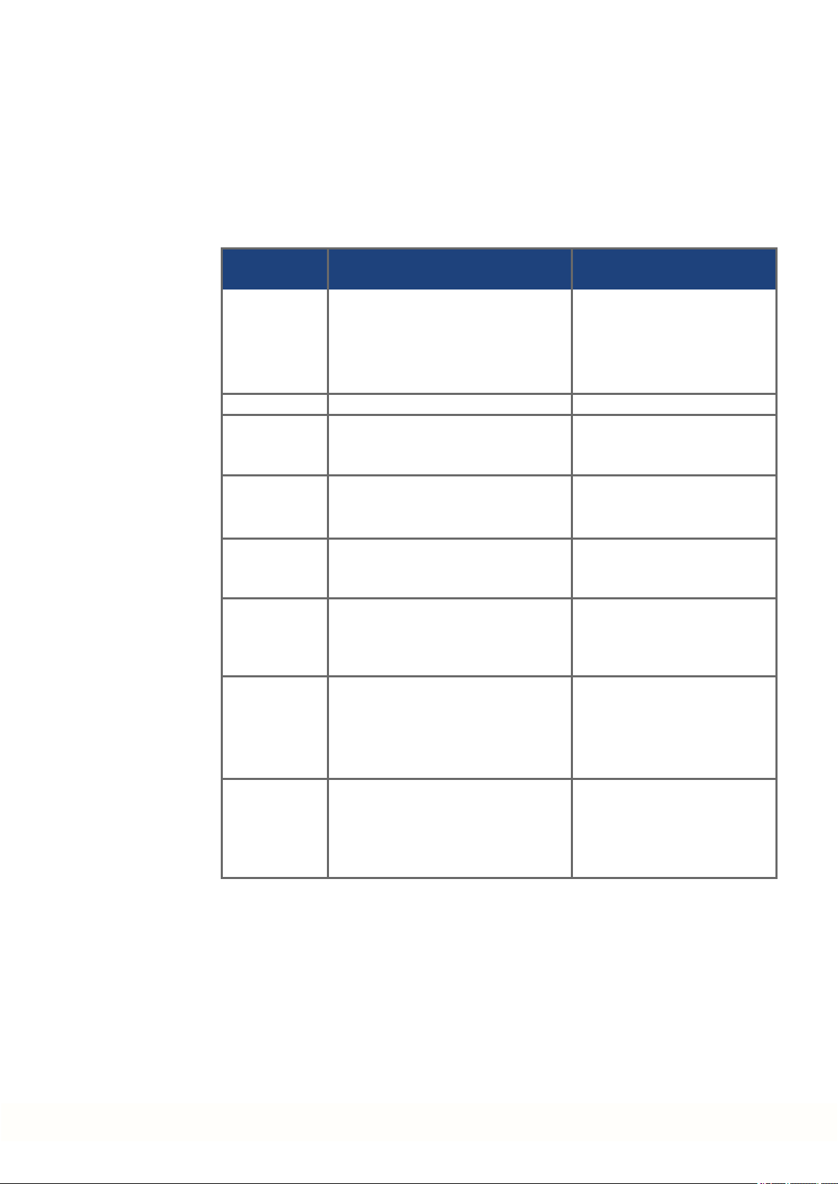
1.3.2 Nameplate
With standard motors the nameplate is adhesive on the housing side. With washdown
motors the nameplate is engraved on the housingside, an additional nameplate is addedto
every motor package.
Legend Description
MODEL motor type
CUST P/N customer part no.
Ics I0rms (standstill current)
Tcs M0 (standstill torque)
Vs Un (DC bus link voltage)
Nrtd nn (rated speed @ Un)
Prtd Pn (rated power)
Year of manufacturingis coded in the serial number: the first two digits of the serial number
arethe year of manufacturing, e.g. "17" means 2017.
10 Kollmorgen | kdn.kollmorgen.com | June 2018
Page 11

1.3.3 Model number description
AKM Installation | 1 English
Kollmorgen | kdn.kollmorgen.com | June 2018 11
Page 12
AKM Installation | 1 English
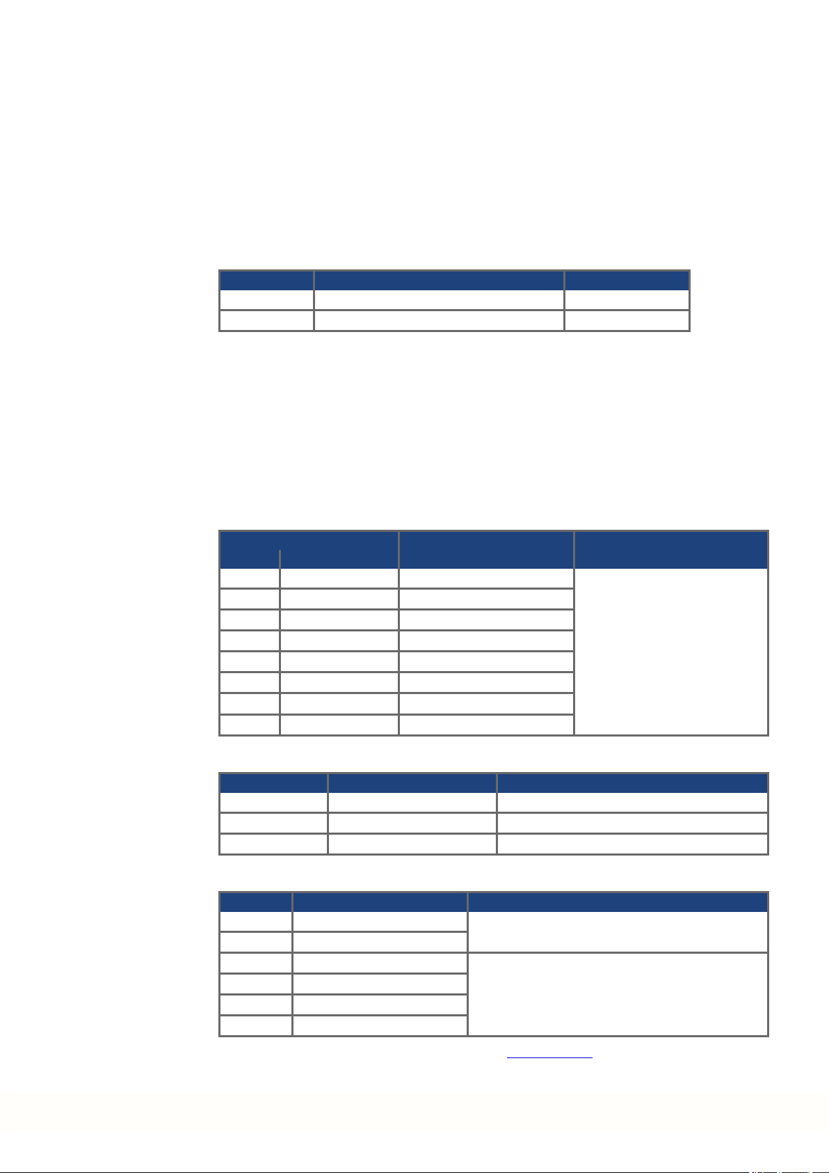
1.3.3.1 Connector Options (C)
Pinout for the connector options are listed in chapter "Connector Pinout" from (➜ # 200).
Technical description of used connectors see KDN (Mating Connectors).
Connector Description
Contacts -
Pins
Connector Usage* Power/Signal Power/Signal Power/Signal
M23
SpeedTec
Ready
(Size 1)
M40 (Size
1.5)
M12 DRIVE-CLiQ - / 8 - / 2 - / 0.5 IP65
M23-6 DRIVE-CLiQ 6 / - 30 / - 4 / - IP65
i-tec Hybrid* 4 / 5 14 / 3.6 1.5 / 0.75 IP65
y-tec
Terminal
box
* Hybrid means: Power and Feedback (plus Brake) on the same connector and in one cable
Power & Brake 4 / 4 30 / 10 4 / 1.5 IP65 BSTA-108-NN-00-08-0036
Feedback - / 12 - / 10 - / 0.5 IP65 ASTA-021-NN-00-10-0035
Feedback - / 17 - / 9 - / 0.5 IP65 ASTA-035-NN-00-10-0035
Hybrid* 4 / 4 30 / 10 4 / 1.5 IP65 BSTA-108-NN-00-08-0036
Power & Brake 4 / 2 75 / 30 16 / 4 IP65 CSTA-263-NN-00-26-0001
Power & Brake 4 / 5 14 / 3.6 1.5 / 0.75 IP65 ESTB-202-NN-00-31-0500
Feedback - / 12 - / 5 - / 0.75 IP65 ESTB-002-NN-00-31-0001
Feedback - / 15 - / 5 - / 0.75 IP65 ESTB-205-NN-00-31-0002
Power & Brake 4 / 2 150 / 15 25 / 2.5 IP65 -
max. Current
[A]
max. Cross
Section [mm²]
Protection
Class
Suggested mating
connector
Standard Siemens
Drive-Cliq cable
ESTB-202-NN-00-1110-
0500
Reference Connector-Motor
KTY 84-
PTC*
D** - 9 1 i-tec Hybrid connector AKM1 Motor mounted
D** - 9
130*
B 1 3 2 SpeedTec Ready connectors AKM2
C 7 4 2 SpeedTec Ready connectors AKM1-AKM2 0.5m cable mounted
C 1 4 2 SpeedTec Ready connectors AKM3-AKM7 (≤ 23,5A)
G - V 2 SpeedTec Ready connectors AKM2-AKM7 (≤ 23,5A)
H - W
- R** -
T 2 X
- U** -
Y 1 Z 1 y-tec connector AKM1 Motor mounted
PT1000* Connection Usable with
1 Hybrid connector SpeedTec
Ready
1 power connector M40, 1 Feedback connector SpeedTec Ready
1 power connector M23-6,
1 Feedback connector M12
1 Terminal box, 1 Feedback connector SpeedTec Ready
1 power connector M23-6,
1 Feedback connector M12
AKM2-AKM6
AKM7xQ & AKM82T
AKM4-AKM7 (≤23,5A)
AKM8 Motor mounted
AKM4-AKM7 (≤23,5A)
Position of connection
Angular, rotatable,
motor mounted
Angular, rotatable,
motor mounted
Angular, rotatable,
motor mounted
Straight, motor mounted
Angular, rotatable,
motor mounted
Motor mounted.
M23-6 angular, rotatable.
M12 Straight.
Straight, motor mounted
* Temperature sensor PTC or KTY or PT1000(➜ # 16)
** With connector options D, R, and U the temperature sensor type depends on the feedback, see (➜ # 14)
12 Kollmorgen | kdn.kollmorgen.com | June 2018
Page 13

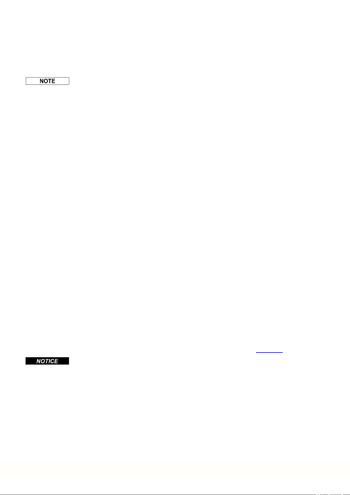
1.3.3.2 Feedback Options (CA)
Motor length depends on the built-infeedback device, see dimension diagrams from (➜ #
186).
Retrofitting is not possible. Pinout for the connector options are listed (➜ # 200).
Technical description of the feedback systems see Kollmorgen Developer Network
(MultiFeedback).
Feedback Description
AKM Installation | 1 English
Code Description Type Remarks
1- Comcoder EPC 15T Single turn, optical 1024 1 All
2- Comcoder EPC 15T Single turn, optical 2048 1 All
AA BiSS B Encoder AD34/AD58 Single turn, optical 2048 1 All
AB BiSS B Encoder AD34/AD58 Multi turn, optical 2048 4096 All
C- SFD Size 10/15/21 Single turn, inductive, 4 lines 11bit 1 AKD
CA SFD3 Size 10/15/21 Single turn, inductive, 2 lines 11bit 1 AKD,S700
DA EnDAT 2.1 Encoder ECN1113/1313 Single turn, optical 512/2048* 1 All
DB EnDAT 2.1 Encoder EQN1125/1325 Multi turn, optical 512/2048* 4096 All
LA EnDAT 2.1 Encoder ECI1118/1319 Single turn, inductive 16/32** 1 All
LB EnDAT 2.1 Encoder EQI1130/1331 Multi turn, inductive 16/32** 4096 All
MA DRIVE-CLiQ Encoder ECN1324S Safety Single turn, optical 24bit 1 Siemens****
MB DRIVE-CLiQ Encoder EQN1336S Safety Multi turn, optical 24bit 4096 Siemens****
GA HIPERFACE Encoder SKS36 Single turn, optical 128 1 Sx
GB HIPERFACE Encoder SKM36 Multi turn, optical 128 4096 Sx
GC HIPERFACE Encoder SEK34 Single turn, capacitive 16 1 Sx
GD HIPERFACE Encoder SEL34 Multi turn, capacitive 16 4096 Sx
GE HIPERFACE DSL Encoder EKS36 Single turn, optical, 18bit 1 AKD,S700
GF HIPERFACE DSL Encoder EKM36 Multi turn, optical,
GJ HIPERFACE Encoder SKS36 Single turn, optical 128 1 AKD
GK HIPERFACE Encoder SKM36 Multi turn, optical 128 4096 AKD
GM Safe HIPERFACE Encoder SKS36S
GN Safe HIPERFACE Encoder SKM36S
GP HIPERFACE Encoder SEK34 Single turn, capacitive 16 1 AKD
GR HIPERFACE Encoder SEL34 Multi turn, capacitive 16 4096 AKD
R- Resolver Size 10/15/21 Single turn, inductive 2 poles 1
Safety, like GJ, SIL2, PLd,
Cat.3
Safety, like GK, SIL2, PLd,
Cat.3
Lines per
rev.
18bit +
12bit
128*** 1 AKD
128*** 4096 AKD
# of
revs.
4096 AKD,S700
usable
with drives
All except
AKD-N
* x/y data for AKM2-4/AKM5-8
** x/y data for AKM2-3/AKM4-8
*** Certificates for safety feedbacks: see Kollmorgen Developer Network (Approvals) or Kollmorgen website.
Kollmorgen | kdn.kollmorgen.com | June 2018 13
Page 14

AKM Installation | 1 English
Reference Feedback-Motor
Connector code (PTC/KTY
84-130/PT1000)
Code Feedback Usable with AKM...
1- Comcoder 2 3-7 1-2 - 2-6 7,82T - 8 - 1
2- Comcoder 2 3-7 1-2 - 2-6 7,82T - 8 - 1
AA BiSS B 2 3-7 2 - 2-6 7,82T - 8 - -
AB BiSS B 2 3-7 2 - 2-6 7,82T - 8 - -
C- SFD* 2 3-7 1-2 1-6 (PTC) 2-6 7,82T - 8 - 1
CA SFD3 - - - 1-6 (PT1000) - - - - - -
DA EnDAT 2.1 2 3-7 2 - 2-6 7,82T - 8 - -
DB EnDAT 2.1 2 3-7 2 - 2-6 7,82T - 8 - -
LA EnDAT 2.1 2 3-7 2 - 2-6 7,82T - 8 - -
LB EnDAT 2.1 2 3-7 2 - 2-6 7,82T - 8 - -
MA DRIVE-CLiQ** - - - - - - 4-7 - 4-7 -
MB DRIVE-CLiQ** - - - - - - 4-7 - 4-7 -
GA Hiperface 2 3-7 2 - 2-6 7,82T - 8 - -
GB Hiperface 2 3-7 2 - 2-6 7,82T - 8 - -
GC Hiperface - - 1 - - - - - - 1
GD Hiperface - - 1 - - - - - - 1
GE Hiperface DSL - - - 2-6 (PT1000) - - - - - -
GF Hiperface DSL - - - 2-6 (PT1000) - - - - - -
GJ Hiperface 2 3-7 2 - 2-6 7,82T - 8 - -
GK Hiperface 2 3-7 2 - 2-6 7,82T - 8 - -
GM Safe Hiperface*** 2 3-7 2 - 2-6 7,82T - 8 - -
GN Safe Hiperface*** 2 3-7 2 - 2-6 7,82T - 8 - -
GP Hiperface - - 1 - - - - - - 1
GR Hiperface - - 1 - - - - - - 1
R- Resolver 2 3-7 1-2 - 2-6 7,82T - 8 - 1
B/1/3 C/1/4 C/7/4 (Kabel) D/-/9 G/-/V H/-/W -/R/- T/2/X -/U/- Y/1/Z
* no brake
** temperature sensor according to current Siemens requirements. For more information contact Kollmorgen.
*** with PTC temperature sensor only
14 Kollmorgen | kdn.kollmorgen.com | June 2018
Page 15
1.4 Technical Description
1.4.1 General technical data
Ambient temperature
(at rated values)
Permissible humidity
(at rated values)
Power derating
(currents and torques)
Ball-bearing life ≥ 20.000 operatinghours
AKM Installation | 1 English
5...+40°C for site altitude up to 1000m amsl
It is vital to consult our applications department for ambient temperatures above 40°C andencapsulated mounting of the
motors.
95% rel. humidity, no condensation
1%/K in range 40°C...50°C up to 1000m amsl
for site altitude above 1000m amsl and 40°C
6% up to 2000m amsl
17% up to 3000m amsl
30% up to 4000m amsl
55% up to 5000m amsl
No derating for site altitudes above 1000m amsl with temperature reduction of 10K / 1000m
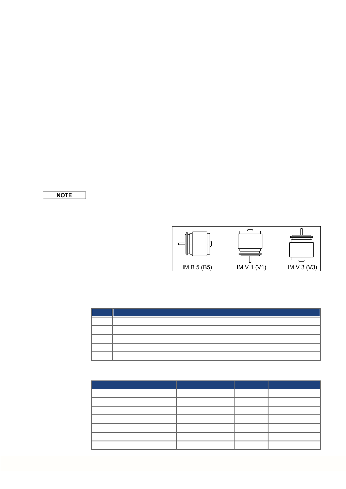
1.4.2 Style
1.4.3 Flange
Technical data for every motor type can be found in chapter "Technical Data" from (➜ #
167).
The basic style for the AKM
motors is style IM B5 according to EN 60034-7.
IEC flange accuracy accordingto DIN 42955. Tolerances of shaft extension run-out and of
mounting flanges for rotating electrical machines.
Code Flange
A IEC with accuracy N, fit AKM1: h7, fit AKM2-8: j6
R IEC with accuracy R, fit AKM1: h7, fit AKM2-8: j6
M IEC with accuracy N, fit j6, reinforced bearing, AKM8 only
W IEC, fit j6,special flange coating for Washdown or Washdown Food motors
B NEMA, dimensions see AKM Selection Guide (Kollmorgen website, US-English)
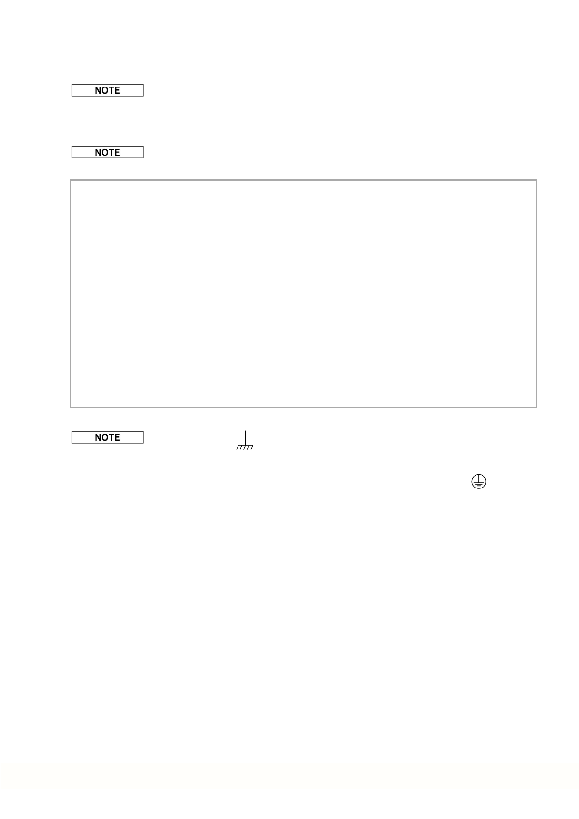
1.4.4 Protection class
Standard Motor Connector Option Shaft Seal Protection class
AKM1 C, D without IP40
AKM1 C, D, Y with IP65
AKM2-AKM7 B, C, D, G, H, T without IP54
AKM8 H, T without IP52
AKM2-AKM8 B, C, D, G, H, T with IP65
AKM2-AKM6 Washdown B, C, D, G with IP67
AKM2-AKM6 Washdown Food B, C, D, G with IP67
Kollmorgen | kdn.kollmorgen.com | June 2018 15
Page 16
AKM Installation | 1 English
1.4.5 Insulation material class
The motors come up to insulation material class F according to IEC 60085 (UL1446 class F).
1.4.6 Surface
The motors are coated with polyester powder coating in matte black. This finish is not resistant against solvents (e.g. trichlorethylene, nitro-thinners, or similar).
1.4.7 Shaft end, A-side
Power transmission is made through the cylindrical shaft end A, fit k6 (AKM1: h7)to
EN50347, with a locking thread but without a fitted keyway.
Motors are also available with keyway and inserted key according to DIN 6885. The shaft
with keyway is balanced with short (half) key.
Bearing life is calculatedwith 20.000 operating hours.
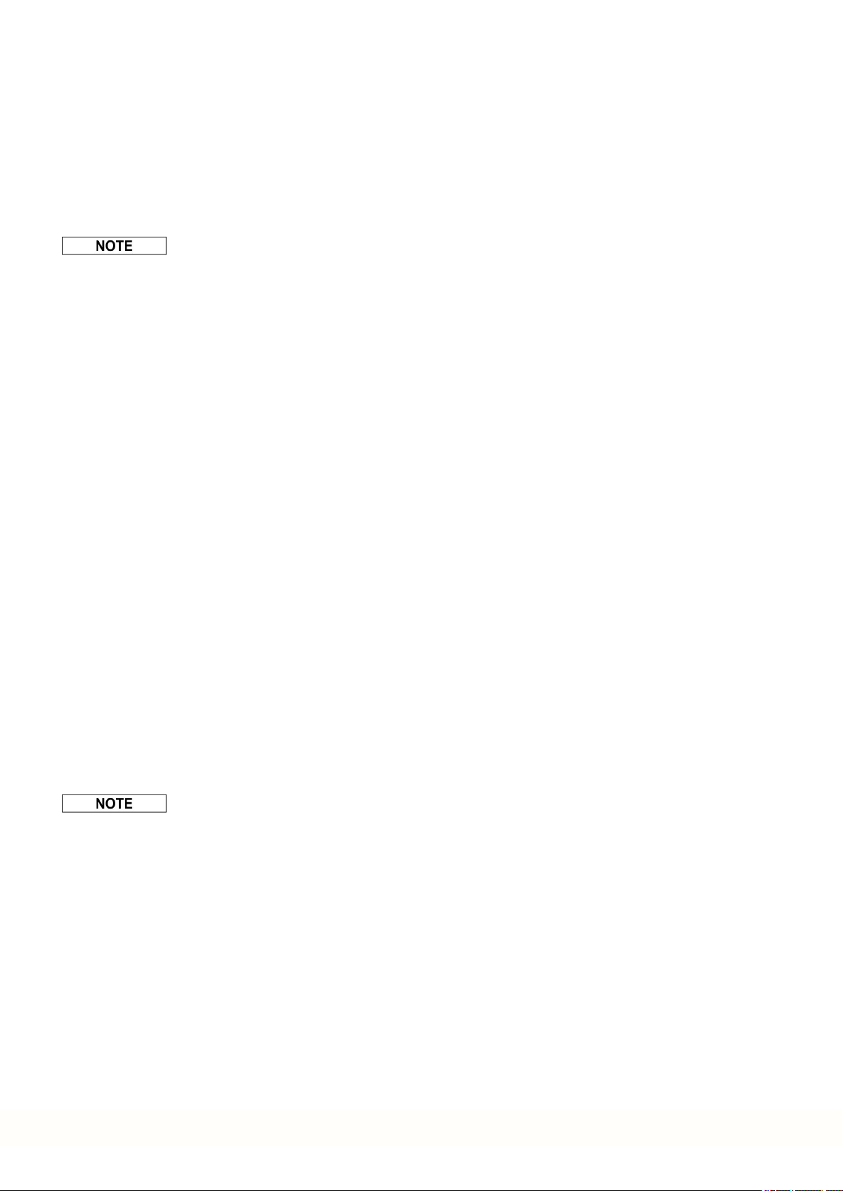
Order code Shaft end Available for
N Smooth shaft all types, standard
C Keyway, closed AKM 2...8
K Keyway, open AKM 1...8
1.4.8 Shaft seal
Radial force
If the motors drive via pinions or toothed belts, then high radial forces will occur. The permissible values at the end of the shaft may be read from the diagrams in chapter "Drawings"
from (➜ # 186). The maximum values at rated speed you will find at the technical data from
(➜ # 167). Power take-off from the middle of the free end of the shaft allows a 10% increase
in FR.
Axial force
When assembling pinions or wheels to the axis and use of e.g. angular gearheads axial
forces arise. The maximum values at rated speed arefound in the technical data.
Coupling
Double-coned collets have proved to be ideal zero-backlash coupling devices, combined, if
required, with metal bellows couplings.
If AKM is connected to a machine flangewith unsealed shaft region, then the shaft seal
(option "01") ensures the shaft sealing.
l The Teflon shaft seal ensures the IP67 protection for the shaft area.
l The ratedperformance is achieved after some hours of shaft seal run-in. No special pro-
cedure for run-in is needed.
l Some “shedding” of Teflon material is normal and does not affect the function.
l Shaft seal operation in dry-running mode is prohibited. Contact Kollmorgen for special shaft
seal solution in case the dry-running operation is required.
l Shaft seal is pre-lubricated by FDA grease.
1.4.9 Protective device
The standard versionof each motor is fitted with an electrically isolatedPTC (rated
temperature155°C ± 5%). The PTC does not provide any protection against short, heavy
overloading.
The motorcan be delivered with a PT1000 or KTY 84-130 sensors optionally (see Connector
Options 1, 2, 7 and D on (➜ # 200)(➜ # 12).
16 Kollmorgen | kdn.kollmorgen.com | June 2018
Page 17
With digital feedback system SFD, SFD3, DSL (C-, CA, GE, GF) the temperature sensor
status is transmitted digitally and evaluated in the drive.
Provided that our configured feedback cables are used, the sensor is integrated into the monitoringsystem of the digital servo amplifiers.
1.4.10 Vibration class
The motors are made to vibration class A according to EN60034-14. For a speed rangeof
600-3600rpm anda shaft center between 56-132mm, this means that the actual value of the
permitted vibration severity is 1.6mm/s.
Velocity [rpm] max. rel. Vibration Displacement [µm] max. Run-out [µm]
<= 1800 90 23
> 1800 65 16
1.4.11 Wiring technology
1.4.11.1 Connectors
Descriptions of the available connectors: (➜ # 12). Connector pinout: from (➜ # 200).
AKM Installation | 1 English
1.4.11.2 Wire cross sections
Power Cable, Combi Cable
Combi cables contain 4 power lines and 2 additional lines for motor holding brake control.
Cross Section Current Carrying
Cable Combi Cable
(4x1) (4x1+(2x0.75)) 0A < I0rms ≤ 10.1A The brackets (...) show the
(4x1.5) (4x1.5+(2x0.75)) 10.1A < I0rms ≤ 13.1A
(4x2.5) (4x2.5+(2x1)) 13.1A < I0rms ≤ 17.4A
(4x4) (4x4+(2x1)) 17.4A < I0rms ≤ 23A
(4x6) (4x6+(2x1)) 23A < I0rms≤ 30A
(4x10) (4x10+(2x1.5)) 30A < I0rms ≤ 40A
(4x16) (4x16+(2x1.5)) 40A < I0rms ≤ 54A
(4x25) (4x25+(2x1.5)) 54A < I0rms ≤ 70A
Feedback Cable
Type Cross Section Remarks
Resolver, SFD (4x2x0.25)
Encoder (7x2x0.25) BiSS, EnDAT, HIPERFACE
Comcoder (8x2x0.25) Incremental Encoder + Hall
Remarks
Capacity
shielding.
Current carrying capacity
acc. to EN60204-1:2006
Table 6, Column B2
Hybrid Cable
Type Cross Section Remarks
SFD (4x1.0+2x(2x0.75)) 4 power lines & 4 signal lines for SFD
respectivelySFD (4x1.5+2x(2x0.75))
SFD3/DSL (4x1.0+(2x0.34)+(2x0.75)) 4 power lines & 2 brake lines &
2 signal lines for SFD3/DSLSFD3/DSL (4x1.5+(2x0.34)+(2x0.75))
SFD3/DSL (4x2.5+(2x0.34)+(2x1.0))
SFD3/DSL (4x4+(2x0.34)+(2x1.0))
Technical description of Hybrid Cable see KDN (Hybrid Cables).
Kollmorgen | kdn.kollmorgen.com | June 2018 17
Page 18

AKM Installation | 1 English
1.4.12 Holding brake
All motors are optionally available with a holdingbrake. A spring appliedbrake (24V DC) is
integratedinto the motors. When this brake is de-energized it blocks the rotor.
WARNING
If there is a suspended load (vertical axes), the motor's holding brake is
released, and, at the same time, the servo drive does not produce any output, the load may fall down! Risk of injury for the personnel operating the
machine. Functional safety in case of hanging loads (vertical axes) can
be ensured only by using an additional, external, mechanical brake.
The holding brakes are designedas standstill brakes and are not suited for repeated operational braking. In the case of frequent, operational braking, premature wear and failure of the
holding brake is to be expected.
The motorlength increases when a holding brake is mounted.
The holding brake can be controlled directly by the servo amplifier (no personal safety !), the
windingis suppressed in the servo amplifier — additional circuitry is not required(see instruction manual of the servo amplifier). If the holding brake is not controlled directly by the servo
drive, an additional wiring (e.g. varistor) is required. Consult our support department.
Brake data are listed in chapter"Technical Data Brakes" from (➜ # 184) .
1.4.13 Fan for AKM7
For the AKM7 model size, an add-onkit for forced ventilation is available. The integrated fan
enables up to 30% more power output for the AKM7 motors. Assembly instructions for the
fan kit is contained within the scope of delivery of the add-on kit.
Make sure, that free airflow is available for the fan. Keep a space of at least 25 mm behind
the fan guard.
The motors become dirty considerably faster due to forced convection. Dirt deposits lead to
falling cooling capacity and can put the motors at risk. Dust may burn in case of overheating.So clean the air duct, the fan, and the motor at regular intervals.
By adding a fan, the mounting dimensions of AKM7 motors increase.
In case of AKM7 motors with connector option "C", winding "Q" and forced ventilation you
must limit the motor current to 23,5A for connector protection.
You can find technical informationon AKM7 motors with fans (➜ # 181).
You can find the dimensional drawing for AKM7 motors with fans on (➜ # 195).
The fan housing can be mounted eitherwith both the supplied
brackets and spacers or with the brackets only. The choice of
mounting method depends on the application. If strong vibrations are expected, you should use both brackets and
spacers. Motors with integrated brakes require the longs
spacers.
18 Kollmorgen | kdn.kollmorgen.com | June 2018
Page 19

1.4.14 Washdown and Washdown Food
These motor variants are used in applications that are subject to strict hygiene regulations in
which it is essential that the formation of nucleation and corrosion are avoided and in which
machines must be cleaned cyclically.
The motors are based on the standard types AKM2 - AKM6 with special modifications for use
in the food-processing industry or even in the packaging industry. In addition, it is also possible to coat the flange in each case – but thenit is not possible to assure tolerance class N
for the flange.
In the type code, the coating of the motor housing (type “W” for Washdown, "F" for Washdown Food) is defined separately in the version (last two digits) and the flange coating.
AKM Installation | 1 English
* Do not turn the connector on the motormore than +/- 180 °, greater rotation angle will damagethe internal connections.
1.4.14.1 Washdown
AKM^^^-^^^^^-^W
AKM^^^-W^^^^^-^W
The Washdown motors must not come into contact with any unpacked foodstuffs.
Application Area: Harsh environments, outdoors
Example: Transport in the foodstuff and packing area without contact with
Standards: UL, CE, RoHS
Surface: Silver coating
Immunity: Against tested industrial cleaning agent (➜ # 20), corrosion-proof
Degree of protection: IP67
Shaft: Stainless steel
Rotary shaft seal: PTFE
Lubricant: Industrial bearing grease, non-food-grade
Connector: Stainless steel, smooth surface
Screws: Stainless Steel
Name plate: Engraved, additional nameplate in the package
Size: AKM2 - AKM6
Washdown/Washdown
Food Motor
AKM2 B*, D*, G
AKM3, 4, 6 C*, D*, G A, B, W, R
AKM5 C*, D*, G B, C, W
Connector
Options
Suggested mating connector Flange
Option B, C, D, G (Hummel M23 INOX connectors):
Power & Brake:
7084943102
Feedback 12-pin:
7004912102
Feedback 18-pin:
7003917102
Options
A, B, W, R
Washdown without flange coating
Washdown with flangecoating of IEC A flange
foodstuff, radar stations, wind turbines, offshore installations
Kollmorgen | kdn.kollmorgen.com | June 2018 19
Page 20
AKM Installation | 1 English
1.4.14.2 Washdown Food
AKM^^^-^^^^^-^F
AKM^^^-W^^^^^-^F
The surface of the Washdown food motor has passed all tests as per FDA GlobalMigration
for indirect contact with foodstuffs. Any direct contact with unpacked foodstuffs is not permitted.
Application Area: Foodstuffs and drinks industry, no direct contact with unpacked
Example: Cutting, packing and filling without direct contact with foodstuffs.
Standards: UL, CE, RoHS, FDA
Surface: White coating
Immunity: Against tested industrial cleaning agent (➜ # 20), corrosion-proof
Global Migration: US FDA Regulations 21 CFR 175.300, Condition of Use E
Degree of protection: IP67
Shaft: Stainless steel
Rotary shaft seal: PTFE as per FDA
Lubricant: food-grade as per FDA
Connector: Stainless steel, smooth surface
Screws: Stainless Steel
Name plate: Engraved, additional nameplate in the package
Size: AKM2 - AKM6
Washdown Food without flange coating
Washdown Food with flange coatingof IEC A flange
foodstuff
Motor laterally or below the food.
1.4.14.3 Tested and confirmed properties with respect to cleaning agents
The testing lab of ECOLAB Deutschland GmbH tested the resistance of the Washdown and
Washdown Food surfaces to the following industrial cleaning agents:
l P3-topactive DES
l P3-topactive LA
l P3-topax 56
l P3-topax 66
l P3-topax 91
In the process, the surfaces were immersed in the respective cleaning agent at room temperature for 28 days. This corresponds to approx. 2,500 cleaning cycles with 15-minute contact each with the cleaningagent or 1,500 cleaningcycles with cleaning andsubsequent
disinfection.
The certificates are located in our Kollmorgen Developer Network on the Approvals page.
Kollmorgen can only give a guarantee for the motor's lifecycle if the tested cleansing agents
areused. Any cleansing agent other than those mentioned above can be tested by Kollmorgen upon request and, if appropriate, be approved.
20 Kollmorgen | kdn.kollmorgen.com | June 2018
Page 21

1.4.14.4 Installation and operating conditions
l The motors may be used only in ambient temperatures up to 50 °C.
l If the front flange is coated, the tolerance class N is not guaranteed.
Motors with flanges without wash-down coating: The flange surface must be protected by
suitable assembly against the influence by cleaning agents.
Duringmounting and operationprotect the motor from mechanical effects which can cause
the scratches or cracks on the painted surface.The mishandling increases risk of corrosion.
1.4.14.5 Cleaning plan
Recommended cleaningplan (short form) with tested cleaningagents:
Flushing with water (40 °... 50 °C)
Flushing with low pressure. From top to bottom in the direction of the drain. Clean the drain.
Foam cleaning
Foaming from top to bottom.
Alkaline: P3-topactive LA or P3-topax 66 (2-5%, 15 min daily)
Acid: P3-topax 56 (2%, if necessary 15 min)
Temperature: cold up to 40 °C
AKM Installation | 1 English
Disinfection
Spraying with wayer (40 °... 50 °C) with low pressure. From top to bottom.
Spray disinfection: P3-topax 91 (1-2%, if necessary 30-60 min)
Foam disinfection: P3-topactiv DES (1-3%, if necessary 10-30min)
Kollmorgen | kdn.kollmorgen.com | June 2018 21
Page 22

AKM Installation | 1 English
1.5 Mechanical Installation
Dimension drawings can be found in chapter "DimensionDrawings"(➜ # 186).
1.5.1 Important Notes
Only qualified staff with knowledge of mechanical engineering are permitted to assemble the
motor.
l Protect the motor from unacceptable stresses. Duringtransport and handling no components
must be damaged.
l The site must be free of conductive and aggressive material. For V3-mounting (shaft end
upwards), make sure that no liquids can enter the bearings. If an encapsulatedassembly is
required, please consult Kollmorgen beforehand.
l Ensure an unhindered ventilation of the motors and observe the permissible ambient and
flange temperatures. For ambient temperatures above 40°C please consult our applications
department beforehand. Ensure that there is adequate heat transfer in the surroundings and
the motor flange.
l Motor flangeand shaft are especially vulnerable during storage and assembly - so avoid brute
force. It is important to use the locking threadwhich is provided to tighten up couplings, gear
wheels or pulley wheels and warm up the drive components, where possible. Blows or the
use of force will lead to damage to the bearings and the shaft.
l Wherever possible, use only backlash-free, frictionally-locking collets or couplings. Ensure
correct alignment of the couplings. A displacement will cause unacceptable vibrationand the
destruction of the bearings and the coupling.
l In all cases, do not create a mechanically constrainedmotor shaft mounting by using a rigid
coupling with additional external bearings (e.g. in a gearbox).
l Take note of the no. of motor poles and the no. of resolver poles (if applicable), andensure
that the correct setting is made in the servo amplifier which is used. An incorrect setting can
leadto the destruction of the motor, especially with small motors.
l Avoid axial loads on the motor shaft, as far as possible. Axial loading significantly shortens
the life of the motor.
l Check the compliance to the permitted radial and axial forces F
andFA. When you use a
R
toothed belt drive, the minimal permitted diameter of the pinion
e.g. follows from the equation: d
≥ (M0/FR)*2
min
22 Kollmorgen | kdn.kollmorgen.com | June 2018
Page 23
1.6 Electrical Installation
Pinout for the connector can be foundin chapter "Connector Pinout" from (➜ # 200). Pinout
of the servo amplifier's end can be found in the instructions manual of the servo amplifier.
1.6.1 Important notes
Only staff qualified and trained in electrical engineering are allowedto wire up the motor.
DANGER
Always make sure that the motors are de-energized during assembly and
wiring, i.e. no voltage may be switched on for any piece of equipment
which is to be connected.
There is a risk of death or severe injury from touching exposed contacts.
Ensure that the switch cabinet remains turned off (barrier, warning signs
etc.). The individual voltages will only be turned on again during setup.
Never undo the electrical connections to the motor while it is energized.
Risk of electric shock! In unfavorable circumstances, electric arcs can
arise causing harm to people and damaging contacts.
AKM Installation | 1 English
A dangerous voltage, resulting from residual charge, can be still present
on the capacitors up to 10 minutes after switch-off of the mains supply.
Even when the motor is not rotating, control and power leads may be live.
Measure the DC-link voltage and wait until it has fallen below 60V.
The ground symbol , which you will find in the wiringdiagrams, indicates that you must
provide an electrical connection, with as large a surface area as possible, between the unit
indicated and the mounting plate in the switch cabinet. This connection is to suppress HF
interference and must not be confused with the PE (protective earth)symbol (protective
measure to EN 60204).
To wire up the motor, use the wiring diagrams in the Installation and Setup Instructions of the
servo amplifierwhich is used.
Kollmorgen | kdn.kollmorgen.com | June 2018 23
Page 24
AKM Installation | 1 English
1.6.2 Guide for electrical installation
l Check that the servo amplifier and motor match each other. Compare the ratedvoltage and
rated current of the unit. Carry out the wiring according to the wiring diagram in the instructions manual of the servo amplifier. The connections to the motor are shown in chapter "Connector Pinout" from (➜ # 200).
l Install all cables carrying a heavy current with an adequate cross-section, as per EN60204.
The recommended cross-section can be found in the Technical data.
In case of long motor cables (>25m) and dependent on the type of the used servo amplifier a
motor choke (3YL or 3YLN) must be switched into the motor cable (see instructions manual
of the servo amplifier and accessory manual).
l Ensure that there is proper earthing of the servo amplifier and the motor. Use correct earthing
andEMC-shielding according to the instructions manual of the servo amplifier which is used.
Earth the mounting plate and motor casing.
l If a motor power cable is used which includes integral brake control leads, then these brake
control leads must be shielded. The shielding must be connected at both ends (see instructions manual of the servo amplifier).
l Cabling:
o
Route power cables as separately as possible from control cables
o
Connect the feedback device.
o
Connect the motor cables, install motor chokes (if applicable)close to the amplifier
o
Connect shields to shielding terminals or EMC connectors at both ends
o
Connect the holding brake, if used
o
Connect shielding at both ends.
l Connect up all shielding via a wide surface-area contact (low impedance) and metallized con-
nector housings or EMC-cable glands.
l Requirements to cable material:
Capacity
Motor cable: less than 150 pF/m
Resolver cable: less than 120 pF/m
1.6.3 Connection of the motors with preassembled cables
l Carry out the wiring in accordance with the valid standards and regulations.
l Only use Kollmorgen preassembledshielded cables for the resolver and power connections.
l Incorrectly installed shielding leads to EMC interference and has an adverse effect on sys-
tem function.
l The maximum cable length is defined in the instructions manual of the used servo amplifier.
For a detailed descriptionof configured cables, please refer to the regional accessories
manual.
24 Kollmorgen | kdn.kollmorgen.com | June 2018
Page 25

1.7 Setup
1.7.1 Important notes
Only specialist personnel with extensive knowledge in the areas of electrical engineering /
drive technology are allowed to commission the drive unit of servo amplifier and motor.
DANGER
Deadly voltages can occur, up to 900 V. Risk of electric shock! Check
that all live connection points are safe against accidental contact.
Never undo the electrical connections to the motor when it is live. Risk of
electric shock! The residual charge in the capacitors of the drive can produce dangerous voltages up to 10 minutes after the mains supply has
been switched off.
Even when the motor is not rotating, control and power leads may be live.
Measure the DC-link voltage and wait until it has fallen below 60 V.
AKM Installation | 1 English
CAUTION
The surface temperature of the motor can exceed 100°C in operation.
Danger of light burns! Check (measure) the temperature of the motor.
Wait until the motor has cooled down below 40°C before touching it.
CAUTION
The drive performing unplanned movements during commissioning cannot be ruled out.
Make sure that, even if the drive starts to move unintentionally, no danger
can result for personnel or machinery.
The measures you must take in this regard for your task are based on the
risk assessment of the application.
Kollmorgen | kdn.kollmorgen.com | June 2018 25
Page 26

AKM Installation | 1 English
1.7.2 Guide for setup
The procedure for setup is described as an example. A different method may be appropriate or necessary, depending on the applicationof the equipment.
1. Check the assembly andorientation of the motor.
2. Check the drive components (clutch, gearunit, belt pulley) for the correct seating and setting
(observe the permissible radial and axial forces).
3. Check the wiringand connections to the motor and the servo amplifier. Check that the earthing is correct.
4. Test the function of the holding brake, if used. (apply 24 V, brake must be released).
5. Check whether the rotor of the motor revolves freely (release the brake, if necessary). Listen
for grindingnoises.
6. Check that all the required measures against accidental contact with live andmoving parts
have been carried out.
7. Carry out any further tests which are specifically required for yoursystem.
8. Now commission the drive according to the setup instructions for the servo amplifier.
9. In multi-axis systems, individually commission each drive unit (amplifierand motor).
26 Kollmorgen | kdn.kollmorgen.com | June 2018
Page 27
1.7.3 Trouble Shooting
The following tableis to be seen as a “First Aid” box. There can be a large numberof different
reasons for a fault, depending on the particular conditions in your system. The fault causes
described below aremostly those which directly influence the motor. Peculiarities which
show up in the control loopbehaviour can usually be traced back to an error in the parameterization of the servo amplifier. The documentation for the servo amplifier and the setup
softwareprovides information on these matters.
For multi-axis systems there may be further hidden reasons for faults.
Fault Possible cause
Motor doesn’t
rotate
Motor runs away — Motor phases in wrong sequence — Correct the phase sequence
Motor oscillates — Break in the shielding of the resolver
Error message:
brake
Error message:
output stage
fault
Error message:
resolver
Error message:
motor tem-
perature
Brake does not
grip
— Servoamplifier not enabled
— Break in setpoint lead
— Motor phases in wrong sequence
— Brake not released
— Drive is mechanically blocked
cable
— amplifier gain to high
— Short-circuit in the supply voltage
leadto the motor holding brake
— Faulty motor holding brake
— Motor cable has short-circuit or earth
short
— Motor has short-circuit or earth short
— Resolver connector is not properly
plugged in
— Break in resolver cable, cable
crushed or similar
— Motor thermosensor has switched
— Loose resolver connector or break in
resolver cable
— Required holding torque too high
— Brake faulty
— Motor shaft axially overloaded
AKM Installation | 1 English
Measures to remove the cause
of the fault
— Supply ENABLE signal
— Check setpoint lead
— Correct the phase sequence
— Check brake controls
— Check mechanism
— Replace resolvercable
— use motor default values
— Remove the short-circuit
— Replace motor
— Replace cable
— Replace motor
— Check connector
— Check cables
— Wait until the motor has
cooleddown. Then investigate
why the motor becomes so hot.
— Check connector, replace
resolver cable if necessary
— Check the dimensioning
— Replace motor
— Check the axial load, reduce
it. Replace motor, since the bearings have been damaged
Kollmorgen | kdn.kollmorgen.com | June 2018 27
Page 28

AKM Installation | 1 English
1.8 Definition of Terms for Technical Data
Technical data for every motor type can be found in chapter "Technical Data" (➜ # 167).
All data valid for 40°C environmental temperature and 100K overtemperature of the winding.
Determination of nominal data with constant temperature of adapter flangeof 65°C. The data
can have a tolerance of +/- 10%.
Standstill torque M0[Nm]
The standstill torque can be maintainedindefinitely at a speed 0<n<100 rpm and rated ambient conditions.
Rated torque Mn[Nm]
The rated torque is producedwhen the motor is drawing the rated current at the rated speed.
The rated torque can be producedindefinitely at the rated speedin continuous operation (S1).
Standstill current I
0rms
[A]
The standstill current is the effective sinusoidal current which the motor draws at 0<n<100
rpm to produce the standstill torque.
Peak current (pulse current) I
0max
[A]
The peak current (effective sinusoidal value) is several times the ratedcurrent depending on
the motor winding. The actual value is determined by the peak current of the drive which is
used.
Torque constant K
Trms
[Nm/A]
The torque constant defines how much torquein Nm is produced by the motor with 1A r.m.s.
current. The relationship is M=I x KT(upto I = 2 x I0).
Voltage constant K
Erms
[mV/min
-1]
The voltageconstant defines the inducedmotor EMF, as an effective sinusoidal value
between two terminals, per 1000 rpm. Measured at 25°C.
Rotor moment of inertia J [kgcm²]
The constant J is a measure of the accelerationcapability of the motor. For instance, at I0the
acceleration time tbfrom 0 to 3000 rpm is given as:
with M0in Nm and J in kgcm²
Thermal time constant tth[min]
The constant tthdefines the time for the cold motor, under a load of I0, to heat up to an overtemperature of 0.63 x 10⁵ Kelvin. This temperature rise happens in a much shortertime when
the motor is loaded with the peak current.
Release delay time t
[ms] / Engage delay time t
BRH
These constants define the response times of the holding brake when operated with the rated
voltage from the servo amplifier.
U
N
Rated mains voltage
U
n
DC-Bus link voltage.
28 Kollmorgen | kdn.kollmorgen.com | June 2018
[ms] of the brake
BRL
Page 29

AKM Installation | 2 Deutsch
2 Deutsch
2.1 Allgemeines 30
2.1.1 Zu diesem Handbuch 30
2.1.2 Verwendete Abkürzungen 30
2.1.3 Verwendete Symbole 30
2.2 Sicherheit 31
2.2.1 Darauf sollten Sie achten 31
2.2.2 Bestimmungsgemäße Verwendung 33
2.2.3 Nicht bestimmungsgemäße Verwendung 33
2.2.4 Handhabung 34
2.3 Produktidentifizierung 36
2.3.1 Lieferumfang 36
2.3.2 Typenschild 36
2.3.3 Typenschlüssel 37
2.4 Technische Beschreibung 41
2.4.1 Allgemeine technische Daten 41
2.4.2 Ausführung 41
2.4.3 Flansch 41
2.4.4 Isolierstoffklasse 41
2.4.5 Oberfläche 41
2.4.6 Wellenende, A-Seite 42
2.4.7 Wellendichtung 42
2.4.8 Schutzeinrichtung 42
2.4.9 Schwingungsklasse 43
2.4.10 Anschlusstechnik 43
2.4.11 Haltebremse 44
2.4.12 Lüfter für AKM7 44
2.4.13 Washdown und Washdown Food 45
2.5 Mechanische Installation 48
2.5.1 Wichtige Hinweise 48
2.6 Elektrische Installation 49
2.6.1 Wichtige Hinweise 49
2.6.2 Leitfaden für die elektrische Installation 50
2.6.3 Anschluss der Motorenmit vorkonfektionierten Leitungen 50
2.7 Inbetriebnahme 51
2.7.1 Wichtige Hinweise 51
2.7.2 Leitfaden für die Inbetriebnahme 52
2.7.3 Beseitigen von Störungen 53
2.8 Begriffsdefinitionen für technische Daten 54
Kollmorgen | kdn.kollmorgen.com | June 2018 29
Page 30
AKM Installation | 2 Deutsch
2.1 Allgemeines
2.1.1 Zu diesem Handbuch
Dieses Handbuch beschreibt die Synchron-Servomotoren der Serie adjust in target (Standardausführung). Die Motoren werden in Antriebssystemenzusammenmit Servoverstärkern
von Kollmorgen betrieben. Beachten Sie daher die gesamte Dokumentationdes Systems,
bestehendaus:
l Betriebsanleitung des Servoverstärkers
l Manuelle Buskommunikation (z.B. CANopen oder EtherCAT)
l Online-Hilfe der Inbetriebnahmesoftware des Servoverstärkers
l Regionales Zubehörhandbuch
l Technische Beschreibung der Motorserie AKM
Weitere Hintergrundinformationen finden Sie im KollmorgenDeveloper Network unter kdn.-
kollmorgen.com.
2.1.2 Verwendete Abkürzungen
Die Abkürzungen für die technischen Daten finden Sie im Kapitel „Begriffsdefinitionen“.
.
54)
In diesem Dokument bedeutet die Symbolik (➜ S. 53): siehe Seite 53.
2.1.3 Verwendete Symbole
Symbol Bedeutung
GEFAHR
WARNUNG
VORSICHT
(➜ #
Weist auf eine gefährliche Situation hin, die, wenn sie nicht
vermiedenwird, zum Tode oder zu schweren, irreversiblen
Verletzungen führen wird.
Weist auf eine gefährliche Situation hin, die, wenn sie nicht
vermiedenwird, zum Tode oder zu schweren, irreversiblen
Verletzungen führen kann.
Weist auf eine gefährliche Situation hin, die, wenn sie nicht
vermiedenwird, zu leichten Verletzungen führen kann.
Dieses Symbol weist auf eine Situationhin, die, wenn sie
nicht vermieden wird, zu Beschädigung von Sachen führen
kann.
Dieses Symbol weist auf wichtige Informationen hin.
30 Kollmorgen | kdn.kollmorgen.com | June 2018
Warnung vor einer Gefahr (allgemein). Die Art der Gefahr wird
durch den nebenstehendenWarntext spezifiziert.
Warnung vor gefährlicher elektrischer Spannung und deren
Wirkung.
Warnung vor heißer Oberfläche.
Warnung vor hängender Last.
Page 31

2.2 Sicherheit
Dieser Abschnitt hilft Ihnen, Gefahren für Personen und Sachwerte zu erkennen und zu vermeiden.
2.2.1 Darauf sollten Sie achten
Fachpersonal ist erforderlich!
Nur qualifiziertes Personal darf Arbeiten wie Transport, Montage, Inbetriebnahme und Wartung ausführen. Qualifiziertes Fachpersonal sind Personen, die mit dem Transport, derInstallation, der Montage, derInbetriebnahme und dem Betrieb von Motoren vertraut sind und ihre
jeweiligen Mindestqualifikationen einbringen:
l Transport: nur durch Personal, das für den Umgang mit elektrostatisch empfindlichen Bau-
teilen geschult ist.
l Mechanische Installation: nur durch Fachleute mit maschinenbautechnischerAusbildung.
l Elektrische Installation nurdurch Fachleute mit elektrotechnischer Ausbildung.
l Inbetriebnahme: nurdurch Fachleute mit weitreichendenKenntnissen in den Bereichen Elek-
trotechnik/Antriebstechnik.
Das Fachpersonal muss die Normen IEC 60364/IEC 60664 und die nationalen Unfall-
verhütungsvorschriften kennen und beachten.
AKM Installation | 2 Deutsch
Lesen Sie die Dokumentation sorgfältig durch!
Lesen Sie vor der Installation und Inbetriebnahmedie vorliegende Dokumentation. Unsachgemäße Handhabung des Motors kann zu Personen-oder Sachschäden führen. Der Betreibermuss daher sicherstellen, dass alle mit Arbeiten am Motor betrauten Personendas
Handbuch gelesen und verstandenhabenund dass die Sicherheitshinweise in diesem Handbuch beachtet werden.
Beachten Sie die technischen Daten!
Halten Sie die technischen Daten und die Angaben zu den Anschlussbedingungen (Typenschild und Dokumentation) ein. Werden zulässige Spannungs- oderStromwerte überschritten, können die Motoren z.B. durch Überhitzung beschädigt werden.
Führen Sie eine Risikobeurteilung durch!
Der Maschinenhersteller muss eine Risikobeurteilung für die Maschine erstellen und
adäquate Maßnahmen ergreifen, um sicherzustellen, dass unvorhergeseheneBewegungen
nicht zu Verletzungenoder Sachschäden führen können. Aus derRisikobeurteilung können
sich darüber hinaus zusätzliche Anforderungen an das Fachpersonal ergeben.
Sorgen Sie für einen sicheren Transport!
Hebenund BewegenSie Motoren mit mehr als 20kg Gewicht (AKM7 und AKM8) nur mit
Hebezeugen. Das Anheben ohne Hilfsmittel kann zu Rückenverletzungen führen. Beachten
Sie stets die Hinweise auf (➜ # 34)
Sichern Sie die Passfeder!
Entfernen Sie eine eventuell vorhandene Passfeder von der Welle, bevor Sie denMotor ohne
angekoppelte Last laufen lassen, um ein gefährliches Herausschleudern der Passfeder durch
Fliehkräfte zu vermeiden. Im Auslieferungszustandist die Passfeder mit einer Kunststoffkappe abgedeckt.
Kollmorgen | kdn.kollmorgen.com | June 2018 31
Page 32

AKM Installation | 2 Deutsch
Heiße Oberfläche!
Die Oberflächen der Motoren können im Betrieb je nach Schutzart sehr heiß werden. Gefahr
von leichten Verbrennungen! Die Oberflächentemperatur kann 100°C überschreiten. Messen Sie die Temperaturund warten Sie, bis der Motorunter 40°C abgekühlt ist, bevor Sie ihn
berühren.
Erdung! Hochspannungen!
Es ist unbedingt darauf zu achten, dass das Motorgehäuse sicher mit derPE-Sammelschiene im Schaltschrank verbunden und somit geerdet ist. Es besteht die Gefahr eines
elektrischen Schlages. Ohne niederohmige Erdung kann kein Schutz für Personen gewährleistet werden undes besteht Lebensgefahr durch Stromschlag.
Der Verzicht auf optische Anzeigen garantiert keine Spannungsfreiheit. Leistungsanschlüsse
können Spannung führen, auch wenn sich die Motorwelle nicht dreht.
Ziehen Sie während des Betriebs keine Stecker ab. Es besteht die Gefahrvon Tod oder
schweren Verletzungen durch Berühren freiliegender Kontakte. Leistungsanschlüsse können
auch bei nicht drehendem Motorunter Spannung stehen. Dies kann zu Überschlägen und
somit zu Personenschäden undBeschädigungender Kontakte führen.
Warten Sie nach dem Trennen des Servoverstärkers von der Versorgungsspannung einige
Minuten, bevor Sie spannungsführende Komponenten(z.B. Kontakte, Schraubverbindungen) berühren oder Anschlüsse öffnen.
Die Kondensatoren im Servoverstärker können auch einige Minuten nach dem Abschalten
derVersorgungsspannungen noch eine gefährliche Spannung führen. Messen Sie zur Sicherheit die Zwischenkreisspannung und warten Sie, bis die Spannung unter60V abgesunken
ist.
Sichern Sie hängende Lasten!
Die eingebauten Haltebremsen gewährleisten keine Funktionssicherheit!
Hängende Lasten (Vertikalachsen)erfordern eine zusätzliche, externe mechanische Bremse
zur Gewährleistung der Arbeitssicherheit.
32 Kollmorgen | kdn.kollmorgen.com | June 2018
Page 33

2.2.2 Bestimmungsgemäße Verwendung
l Die Synchron-Servomotorender Serie AKM sind speziell als Antriebe für Industrieroboter,
Werkzeugmaschinen, Textil- und Verpackungsmaschinen und ähnliche Anwendungen mit
hohen Ansprüchen an die Dynamik konzipiert.
l Der Anwender darf die Motoren nurunter den in dieserDokumentation definierten Umge-
bungsbedingungenbetreiben.
l Der Einsatz von wassergeschützten Motoren in Umgebungen mit ätzenden Säuren und Lau-
genist unter den auf Seite (➜ # 45)definierten Bedingungen zulässig.
l Der Einsatz von wassergeschützten Motoren in der Lebensmittelindustrie ist bei Anwen-
dungen mit indirektem Kontakt zu Lebensmitteln undGetränken zulässig.
l Die Motoren derSerieAKM sind ausschließlich dazu bestimmt, von digitalen Ser-
voverstärkern drehzahl- und/oderdrehmomentgeregelt angesteuert zu werden.
l Die Motoren werden als Bauteile in elektrische Anlagenoder Maschinen eingebaut und dür-
fen nur als integrierte Bauteile der Anlage in Betrieb genommen werden.
l Der in denMotorwicklungeneingebaute Thermosensor muss überwacht undentsprechend
ausgewertet werden.
l Die Haltebremsen sind als Stillstandsbremsen ausgelegt und für betriebsmäßige Abbrems-
vorgänge ungeeignet.
l Die Konformität des Servosystems zu den in der CE-Konformitätserklärung (➜ # 207)
genannten Normen ist nur gewährleistet, wenn die verwendeten Komponenten (Servoverstärker, Motor, Kabel usw.) von Kollmorgen geliefert wurden.
AKM Installation | 2 Deutsch
2.2.3 Nicht bestimmungsgemäße Verwendung
l Die Verwendung derstandardmäßigen Motoren in folgenden Umgebungen ist verboten:
o
direkt am Stromnetz,
o
in explosionsgefährdeten Bereichen,
o
bei Kontakt mit Lebensmitteln und Getränken,
o
in Umgebungen mit ätzenden und/oder elektrisch leitendenSäuren, Laugen, Ölen, Dämpfen, Stäuben.
l Die Verwendung derwassergeschützten Motoren in folgendenUmgebungen ist verboten:
o
direkt am Stromnetz,
o
in explosionsgefährdeten Bereichen,
o
bei Kontakt mit Lebensmitteln und Getränken,
o
in Umgebungen mit Säuren oder Basen mit einem pH-Wert unter 2 oderüber 12,
o
in Umgebungen mit Säuren oder Laugen, die nicht von Kollmorgen geprüft wurden.
l Die Verwendung derwassergeschützten Motoren zur Verarbeitung von Lebensmitteln
in folgenden Umgebungen ist verboten:
o
direkt am Stromnetz,
o
in explosionsgefährdeten Bereichen,
o
bei direktem Kontakt mit Lebensmitteln und Getränken.
l Die Inbetriebnahme des Motors ist untersagt, wenn die Maschine, in die er eingebaut wurde,
o
nicht den Bestimmungen derEG-Maschinenrichtlinie entspricht,
o
nicht die Bestimmung der EMV-Richtlinie erfüllt,
o
nicht die Bestimmung der Niederspannungs-Richtlinie erfüllt.
l Die eingebautenHaltebremsen dürfen ohneweitere Ausstattung nicht zur Gewährleistung
derFunktionssicherheit verwendet werden.
Kollmorgen | kdn.kollmorgen.com | June 2018 33
Page 34

AKM Installation | 2 Deutsch
2.2.4 Handhabung
2.2.4.1 Transport
l Klimaklasse 2K3 nach IEC 60721-3-2,EN61800-2
l Temperatur: -25..+70°C, max. 20K/Stunde schwankend
l Luftfeuchtigkeit: relative Feuchte 5% ... 95% nicht kondensierend
l Nur von qualifiziertem Personal in der Original-Verpackungdes Herstellers
l Vermeiden Sie harte Stöße, insbesondere auf das Wellenende
l ÜberprüfenSie bei beschädigter Verpackungden Motor auf sichtbare Schäden. Informieren
Sie den Transporteurund gegebenenfalls den Hersteller.
Transport von Motoren über 20kg Gewicht
Verwenden Sie für den sicheren Transport der Motoren AKM7 und AKM8 (>20kg) die beiliegenden Hebeösen. Beachten Sie die in der Motorverpackung beiliegendeAnweisungen für
denTransport.
Als Zubehörzum Transport der Motorenempfehlen wir die Transportvorrichtung
ZPMZ120/292.
Die Transportvorrichtung ZPMZ 120/292 besteht aus einer Traverse, die am Kranhaken eingehängt wird undzwei zweiadrigen Kettenanschlägen.
GEFAHR
Schwebende Last. Lebensgefahr wenn die Last abstürzt. Treten Sie während des Hebevorgangs niemals unter die Last!
l die Befestigungsschrauben derHebeösen müssen vollständig eingedreht sein
l die Hebeösen müssen ebenund vollflächig auf der Auflagefläche aufliegen
l Die Hebeösen vor dem Gebrauch auf festen Sitz und augenfällige Beschädigungen (Kor-
rosion, Verformung) überprüfen.
l Hebeösen mit Verformungen dürfen nicht weiterbenutzt werden.
34 Kollmorgen | kdn.kollmorgen.com | June 2018
Page 35

2.2.4.2 Verpackung
l Kartonverpackung mit Instapak®-Ausschäumung.
l Den Kunststoffanteil können Sie an den Lieferanten zurückgeben
AKM Installation | 2 Deutsch
Motortyp Verpackung Max. Sta-
AKM1 Karton 10 AKM5 Karton 5
AKM2 Karton 10 AKM6 Karton 1
AKM3 Karton 6 AKM7 Karton 1
AKM4 Karton 6 AKM8 Mini-Palette 1
2.2.4.3 Lagerung
l Klimaklasse 1K4 nach IEC 60721-3-1,EN61800-2
l Lagertemperatur-25...+55°C, max. 20K/Stundeschwankend
l Luftfeuchtigkeitrelative Feuchte 5% ... 95% nicht kondensierend
l Nur in derOriginalverpackung des Herstellers lagern
l Max. Stapelhöhe:siehe Tabelle in Kapitel "Verpackung"
l Lagerdauer:ohne Einschränkung
2.2.4.4 Wartung / Reinigung
l Wartung und Reinigung nurvon qualifiziertem Personal.
l Nach 20.000 Betriebsstundenunter Nennbedingungen sollten die Kugellagererneuert wer-
den(vom Hersteller).
l Prüfen Sie den Motoralle 2500 Betriebsstunden bzw. einmal jährlich auf Kugel-
lagergeräusche. Wenn Sie Geräusche feststellen, darf der Motor nicht weiterbetrieben werden- die Lager müssen vom Hersteller erneuert werden.
l Öffnen der Motorenbedeutet den Verlust der Gewährleistung.
l Gehäusereinigung mit Isopropanol o.ä., nicht tauchen oder absprühen.
pelhöhe
Motortyp Verpackung Max. Sta-
pelhöhe
2.2.4.5 Reparatur / Entsorgung
Reparaturen des Motors darf nur der Hersteller durchführen, Öffnen der Geräte bedeutet Verlust derGewährleistung. Gemäß der WEEE-2002/96/EG-Richtliniennehmen wir Altgeräte
undZubehör zur fachgerechtenEntsorgung zurück, sofern die Transportkosten vom Absenderübernommen werden. Schicken Sie den Motor an:
KOLLMORGEN Europe GmbH
Pempelfurtstr. 1
D-40880 Ratingen
Kollmorgen | kdn.kollmorgen.com | June 2018 35
Page 36

AKM Installation | 2 Deutsch
2.3 Produktidentifizierung
2.3.1 Lieferumfang
l Motor derSerie AKM
l Produkthandbuch (mehrsprachig) gedruckt, eines pro Lieferung
2.3.2 Typenschild
Bei Standardmotorenist das Typenschild gehäuseseitig verklebt. Bei wassergeschützten
Motoren ist das Typenschild auf der Gehäuseseite eingraviert. Ein zusätzliches Typenschild
ist jedem Motorpaket beigefügt.
Legende Beschreibung
MODELL Motortyp
CUST P/N Kunden-Teilenummer
Ics I0rms (Stillstandsstrom)
Tcs M0 (Stillstandsdrehmoment)
Vs Un (Zwischenkreisspannung)
Nrtd nn (Nenndrehzahl bei Un)
Prtd Pn (Nennleistung)
Das Herstellungsjahr ist in der Seriennummer kodiert: die ersten beiden Ziffern derSeriennummer sind das Herstellungsjahr, z.B. „17“bezeichnet das Jahr 2017.
36 Kollmorgen | kdn.kollmorgen.com | June 2018
Page 37

2.3.3 Typenschlüssel
AKM Installation | 2 Deutsch
Kollmorgen | kdn.kollmorgen.com | June 2018 37
Page 38

AKM Installation | 2 Deutsch
2.3.3.1 Anschluss Optionen (C)
Die Steckerbelegungen für Leistung und Feedback finden Sie ab (➜ # 200).
Die technische Beschreibung der diversen Stecker finden Sie im Kollmorgen Developer Network
(Gegenstecker).
Anschluss Beschreibung
Kontakte
Steckertyp Verwendung* Power/Signal Power/Signal Power/Signal
Leistung &
M23 SpeedTec
Ready (Größe
1)
M40 (Größe
1.5)
M12 DRIVE-CLiQ - / 8 - / 2 - / 0,5 IP65
M23-6 DRIVE-CLiQ 6 / - 30 / - 4 / - IP65
i-tec Hybrid* 4 / 5 14 / 3.6 1.5 / 0.75 IP65
y-tec
Klemmkasten
* Hybrid bedeutet: Leistung und Feedback (Bremse) am selben Stecker und in einer Leitung.
Bremse
Feedback - / 12 - / 10 - / 0.5 IP65 ASTA-021-NN-00-10-0035
Feedback - / 17 - / 9 - / 0.5 IP65 ASTA-035-NN-00-10-0035
Hybrid* 4 / 4 30 / 10 4 / 1.5 IP65 BSTA-108-NN-00-08-0036
Leistung &
Bremse
Leistung &
Bremse
Feedback - / 12 - / 5 - / 0.75 IP65 ESTB-002-NN-00-31-0001
Feedback - / 15 - / 5 - / 0.75 IP65 ESTB-205-NN-00-31-0002
Leistung &
Bremse
4 / 4 30 / 10 4 / 1.5 IP65 BSTA-108-NN-00-08-0036
4 / 2 75 / 30 16 / 4 IP65 CSTA-263-NN-00-26-0001
4 / 5 14 / 3.6 1.5 / 0.75 IP65 ESTB-202-NN-00-31-0500
4 / 2 150 / 15 25 / 2.5 IP65 -
max. Strom
[A]
max. Quer-
schnitt [mm²]
Schutz-
klasse
Empfohlene Gegenstecker
Standard Siemens Drive-
ESTB-202-NN-00-1110-0500
Anschluss-Motor Referenz
Cliq-Kabel
PTC*
* Temperatursensor PTC oder KTY oder PT1000 (➜ # 42)
** Bei Steckeroptionen D, R und U hängt die Art des Temperatursensors vom Feedbacktyp ab, siehe (➜ # 40)
KTY
84-130*
B 1 3 2 SpeedTec Ready M23 Stecker AKM2
C 7 4 2 SpeedTec Ready M23 Stecker AKM1-AKM2 An 0,5m Kabel.
C 1 4 2 SpeedTec Ready M23 Stecker
D** - 9 1 i-tec Hybrid Stecker AKM1 Auf Motor montiert.
D** - 9 1 Hybrid Stecker SpeedTec Ready M23 AKM2-AKM6
G - V 2 SpeedTec Ready M23 Stecker
H - W
- R** -
T 2 X
- U** -
Y 1 Z 1 y-tec Stecker AKM1 Auf Motor montiert.
PT1000* Anschlussart Verwendbar mit
AKM3-AKM7
(≤23,5A)
AKM2-AKM7
(≤23,5A)
1 Leistungsstecker M40,
1 Feedbackstecker SpeedTec Ready M23
1 Leistungsstecker M23-6,
1 Feedbackstecker M12
1 Klemmkasten,
1 Feedbackstecker SpeedTec Ready M23
1 Leistungsstecker M23-6,
1 Feedbackstecker M12
AKM7xQ & AKM82T
AKM4-AKM7
(≤23,5A)
AKM8 Auf Motor montiert.
AKM4-AKM7
(≤23,5A)
Position des Anschlusses
Abgewinkelt, drehbar,
auf Motor montiert.
Abgewinkelt, drehbar,
auf Motor montiert.
Abgewinkelt, drehbar,
auf Motor montiert.
Gerade, auf Motor montiert.
Abgewinkelt, drehbar,
auf Motor montiert.
Auf Motor montiert.
M23-6 abgewinkelt,
drehbar.
M12 gerade.
Gerade, auf Motor montiert.
38 Kollmorgen | kdn.kollmorgen.com | June 2018
Page 39

AKM Installation | 2 Deutsch
2.3.3.2 Feedback Optionen (DA)
Die Motorlänge hängt von der eingebautenRückführeinheit (Feedback) ab, siehe Maßzeichnungen ab (➜ # 186).
Ein nachträglicherEinbau ist nicht möglich. Die Steckerbelegungen für die Optionen finden Sie ab (➜ # 200).
Die technische Beschreibung der diversen Feedback Systeme finden Sie im Kollmorgen DeveloperNetwork
(Multi-Feedback).
Feedback Beschreibung
Code Bezeichnung Type Bemerkung
1- Comcoder EPC 15T Single Turn, optisch 1024 1 Alle
2- Comcoder EPC 15T Single Turn, optisch 2048 1 Alle
AA BiSS B Encoder AD34/AD58 Single Turn, optisch 2048 1 Alle
AB BiSS B Encoder AD34/AD58 Multi Turn, optisch 2048 4096 Alle
C- SFD Size 10/15/21 Single Turn, induktiv, 4 adrig 11bit 1 AKD
CA SFD3 Size 10/15/21 Single Turn, induktiv, 2 adrig 11bit 1 AKD,S700
DA EnDAT 2.1 Encoder ECN1113/1313 Single Turn, optisch 512/2048* 1 Alle
DB EnDAT 2.1 Encoder EQN1125/1325 Multi Turn, optisch 512/2048* 4096 Alle
LA EnDAT 2.1 Encoder ECI1118/1319 Single Turn, induktiv 16/32** 1 Alle
LB EnDAT 2.1 Encoder EQI1130/1331 Multi Turn, induktiv 16/32** 4096 Alle
MA DRIVE-CLiQ Encoder ECN1324S Safety Single Turn, optisch 24bit 1 Siemens****
MB DRIVE-CLiQ Encoder EQN1336S Safety Multi Turn, optisch 24bit 4096 Siemens****
GA HIPERFACE Encoder SKS36 Single Turn, optisch 128 1 Sx
GB HIPERFACE Encoder SKM36 Multi Turn, optisch 128 4096 Sx
GC HIPERFACE Encoder SEK34 Single Turn, kapazitiv 16 1 Sx
GD HIPERFACE Encoder SEL34 Multi Turn, kapazitiv 16 4096 Sx
GE HIPERFACE DSL Encoder EKS36 Single Turn, optisch, 18bit 1 AKD,S700
GF HIPERFACE DSL Encoder EKM36 Multi Turn, optisch,
GJ HIPERFACE Encoder SKS36 Single Turn, optisch 128 1 AKD
GK HIPERFACE Encoder SKM36 Multi Turn, optisch 128 4096 AKD
GM Safe HIPERFACE Encoder SKS36S
GN Safe HIPERFACE Encoder SKM36S
GP HIPERFACE Encoder SEK34 Single Turn, kapazitiv 16 1 AKD
GR HIPERFACE Encoder SEL34 Multi Turn, kapazitiv 16 4096 AKD
R- Resolver Size 10/15/21 Single Turn, induktiv 2 polig 1
Safety, wie GJ, SIL2, PLd,
Kat.3
Safety, wie GK, SIL2, PLd,
Kat.3
Striche/
Umdr.
18bit +
12bit
128*** 1 AKD
128*** 4096 AKD
Anzahl
Umdr.
Verwendbar
nur mit
4096 AKD,S700
Alle außer
AKD-N
* x/y Daten für AKM2-4/AKM5-8
** x/y Daten für AKM2-3/AKM4-8
*** Zertifikate für sichere Geber finden Sie im Kollmorgen Developer Network (Zulassungen) oder auf der Kollmorgen
Website.
****Aus rechtlichen Gründen dürfen wir kein Laufwerk anbieten, das dieses Rückmeldegerät unterstützt. Für detaillierte Informationen kontaktieren Sie bitte unseren technischen Support.
Alle Kollmorgen Servoamplifiers werden in Europa S200, S300, S400, S600, S700, AKD, AKD-N angeboten
Kollmorgen | kdn.kollmorgen.com | June 2018 39
Page 40

AKM Installation | 2 Deutsch
Feedback-Motor Referenz
Steckercode (PTC/KTY 84-
130/PT1000)
Code Feedback Verfügbar für AKM...
1- Comcoder 2 3-7 1-2 - 2-6 7,82T - 8 - 1
2- Comcoder 2 3-7 1-2 - 2-6 7,82T - 8 - 1
AA BiSS B 2 3-7 2 - 2-6 7,82T - 8 - -
AB BiSS B 2 3-7 2 - 2-6 7,82T - 8 - -
C- SFD* 2 3-7 1-2 1-6 (PTC) 2-6 7,82T - 8 - 1
CA SFD3 - - - 1-6 (PT1000) - - - - - -
DA EnDAT 2.1 2 3-7 2 - 2-6 7,82T - 8 - -
DB EnDAT 2.1 2 3-7 2 - 2-6 7,82T - 8 - -
LA EnDAT 2.1 2 3-7 2 - 2-6 7,82T - 8 - -
LB EnDAT 2.1 2 3-7 2 - 2-6 7,82T - 8 - -
MA DRIVE-CLiQ** - - - - - - 4-7 - 4-7 -
MB DRIVE-CLiQ** - - - - - - 4-7 - 4-7 -
GA Hiperface 2 3-7 2 - 2-6 7,82T - 8 - -
GB Hiperface 2 3-7 2 - 2-6 7,82T - 8 - -
GC Hiperface - - 1 - - - - - - 1
GD Hiperface - - 1 - - - - - - 1
GE Hiperface DSL - - - 2-6 (PT1000) - - - - - -
GF Hiperface DSL - - - 2-6 (PT1000) - - - - - -
GJ Hiperface 2 3-7 2 - 2-6 7,82T - 8 - -
GK Hiperface 2 3-7 2 - 2-6 7,82T - 8 - -
GM Safe Hiperface*** 2 3-7 2 - 2-6 7,82T - 8 - -
GN Safe Hiperface*** 2 3-7 2 - 2-6 7,82T - 8 - -
GP Hiperface - - 1 - - - - - - 1
GR Hiperface - - 1 - - - - - - 1
R- Resolver 2 3-7 1-2 - 2-6 7,82T - 8 - 1
B/1/3 C/1/4 C/7/4 (Kabel) D/-/9 G/-/V H/-/W -/R/- T/2/X -/U/- Y/1/Z
* ohne Bremse
** Temperatursensor gemäß aktueller Siemens Anforderung. Für weitere Informationen kontaktieren Sie Kollmorgen.
*** nur mit Temperatursensor PTC
40 Kollmorgen | kdn.kollmorgen.com | June 2018
Page 41

2.4 Technische Beschreibung
2.4.1 Allgemeine technische Daten
Umgebungstemperatur
(bei Nennwerten)
Zulässige Luftfeuchtigkeit
(bei Nennwerten)
Leistungsreduzierung
(Ströme und Drehmomente)
Lebensdauer Kugellager ≥ 20.000Betriebsstunden
AKM Installation | 2 Deutsch
5...+40°C bei einer Aufstellhöhe bis 1000m über NN.
Sprechen Sie bei Umgebungstemperaturen über 40°C und bei
gekapseltem Einbauder Motoren unbedingt mit unserer Applikationsabteilung.
95% relative Feuchtigkeit, nicht kondensierend
1%/K im Bereich 40°C...50°C bis 1000m über NN.
Bei Aufstellhöhen über 1000m über NN und 40°C
6% bei 2000m über NN
17% bei 3000m über NN
30% bei 4000m über NN
55% bei 5000m über NN
Keine Leistungsreduzierung bei Aufstellhöhen über 1000m über
NN und Temperaturreduzierung um 10K/1000m
2.4.2 Ausführung
2.4.3 Flansch
Die technischen Daten für jeden Motortyp findenSie im Kapitel „Technische Daten“auf (➜
# 167).
Die Grundbauform der Motoren
AKM ist die Bauform IM B5
nach DIN EN 60034-7.
IEC-Flanschgenauigkeit nach DIN 42955. Toleranzen des Wellenauslaufs und des Montageflansches bei rotierenden elektrischenMaschinen.
Code Flansch
A IEC mit Genauigkeit N, Passung AKM1: h7, Passung AKM2–8: j6
R IEC mit Genauigkeit R, Passung AKM1: h7, Passung AKM2–8: j6
M IEC mit Genauigkeit N, Passung j6, verstärktes Lager, AKMnur 8:
W IEC, Passung j6, spezielle Flanschbeschichtung für wassergeschützte Motoren,
auch für die Lebensmittelindustrie.
B NEMA, Abmessungen siehe „AKM Selection Guide“ (Webseite von Kollmorgen,
englischsprachig)
2.4.4 Isolierstoffklasse
Die Motoren entsprechen derIsolierstoffklasse F nach IEC 60085 (UL1446 Klasse F).
2.4.5 Oberfläche
Die Motoren sind beschichtet mit: Polyester Pulverbeschichtung in mattschwarz. Diese
Beschichtung ist nicht beständig gegenLösungsmittel (z.B. Trichlorethylen, Nitroverdünner
o. ä.).
Kollmorgen | kdn.kollmorgen.com | June 2018 41
Page 42

AKM Installation | 2 Deutsch
2.4.6 Wellenende, A-Seite
Die Kraftübertragung erfolgt über das zylindrische Wellenende A, Passungk6 (AKM1: h7)
nach DIN EN 50347 mit Anzugsgewinde, jedoch ohne Passfedernut.
Die Motoren sind auch mit Passfedernut und eingesetzter Passfeder nach DIN6885 erhältlich. Die Wuchtung der Welle mit Passfedernut erfolgt mit kurzer(halber) Passfeder.
Für die Lebensdauer der Lager sind 20.000 Betriebsstunden zugrunde gelegt.
Bestellcode Wellenende Verfügbar für
N Glatte Welle alle Typen, Standard
C Passfedernut, geschlossen AKM 2...8
K Passfedernut, offen AKM 1...8
Radialkraft
Treiben dieMotorenüber Ritzel oder Zahnriemen an, so treten hohe Radialkräfte auf. Die
zulässigen Werte am Wellenende können den Diagrammen im Kapitel „Zeichnungen“entnommen werden (➜ # 186). Die Maximalwerte bei Nenndrehzahl finden Sie in den technischen Daten auf (➜ # 167). Bei Kraftangriff an derMitte des freienWellenendes kann FR
10% größer sein.
Axialkraft
Bei der Montage von Ritzeln oder Riemenscheiben an die Achse und der Verwendung von
z.B. Winkelgetrieben treten Axialkräfte auf. Die Maximalwerte bei Nenndrehzahl finden Sie
in den technischenDaten.
Kupplung
Als ideale spielfreie Kupplungselemente haben sich doppelkonische Spannzangen, eventuell
in Verbindung mit Metallbalg-Kupplungen, bewährt.
2.4.7 Wellendichtung
Wird AKM an einen Maschinenflansch mit nicht abgedichtetem Wellenbereich angeschlossen, so sorgt die Wellendichtung (Option „01“) für die Abdichtung der Welle.
l Die Teflon-Wellendichtung gewährleistet die Schutzart IP67 für den Wellenbereich.
l Die Nennleistung wird nach einigen Stunden des Einlaufens derWellendichtung erreicht. Ein
speziellerEinlaufprozess ist nicht erforderlich.
l Ein leichtes „Ablösen“des Teflonmaterials ist üblich und beeinträchtigt die Funktion nicht.
l Der Betrieb der Wellendichtung im Trockenlauf ist verboten. Wenn ein Trockenlauf erfor-
derlich ist, wenden Sie sich bitte an Kollmorgen.
l Die Wellendichtung ist mit einem Schmierfett gemäß den Vorgaben der FDA (US-ame-
rikanische Lebensmittel- und Arzneimittelbehörde) vorgeschmiert.
2.4.8 Schutzeinrichtung
In der Standardausführung ist jeder Motormit einem potentialfreien PTC Temperatursensor
ausgestattet. Der Schaltpunkt liegt bei 155°C ± 5%. Schutz gegen kurzzeitige, sehr hohe
Überlastung bietet der PTC nicht.
Optional kann derMotor mit einem PT1000, KTY 84-110Sensoren ausgerüstet werden
(siehe Anschlussoption (➜ # 200)(➜ # 38)
Bei den digitalen Feedbacks SFD, SFD3, DSL (C-, CA, GE, GF) wird der Status des Temperatursensors digital übertragen und im Servoverstärker ausgewertet.
Der Sensor ist bei Verwendung unserer konfektioniertenFeedbackleitungen in das Überwachungssystem der digitalen Servoverstärker integriert.
42 Kollmorgen | kdn.kollmorgen.com | June 2018
Page 43

2.4.9 Schwingungsklasse
Die Motoren sind in der Schwingungsklasse A nach DIN EN 60034-14 ausgeführt. Das
bedeutet bei einem Drehzahlbereich von 600–3600U/min und einem Wellenmittelpunkt zwischen 56–132mm beträgt dertatsächliche Wert derzulässigen Schwingstärke 1,6mm/s.
Drehzahl [U/min] max. rel. Schwingweg [µm] max. Run-out [µm]
<= 1800 90 23
> 1800 65 16
2.4.10 Anschlusstechnik
2.4.10.1 Stecker
Beschreibungender verfügbaren Stecker: (➜ # 37). Steckerbelegung: von (➜ # 200).
2.4.10.2 Leitungsquerschnitte
Leistungsleitungen, Kombikabel
Kombikabel enthalten 4 Leistungsleitungen und 2 zusätzliche Leitungen zur Steuerungder
Motorhaltebremse.
AKM Installation | 2 Deutsch
Querschnitt Strombelastbarkeit Bemerkung
Kabel Kombikabel
(4x1) (4x1+(2x0,75)) 0A < I0rms≤ 10,1A Die Klammern(....) kennzeichnen die Abschirmung.
(4x1,5) (4x1,5+(2x0,75)) 10,1A < I0rms≤ 13,1A
(4x2,5) (4x2,5+(2x1)) 13,1A < I0rms≤ 17,4A
(4x4) (4x4+(2x1)) 17,4A < I0rms≤ 23A
(4x6) (4x6+(2x1)) 23A < I0rms≤ 30A
(4x10) (4x10+(2x1,5)) 30A < I0rms≤ 40A
(4x16) (4x 16 +(2x1,5)) 40A < I0rms≤ 54A
(4 x25) (4x25+(2x1,5)) 54A < I0rms≤ 70A
Rückführkabel
Typ Querschnitt Bemerkung
Resolver, SFD (4x2x0,25)
Encoder (7x2x0,25) BiSS, EnDAT, HIPERFACE
ComCoder (8x2x0,25) Inkrementalgeber + Hall
Hybridkabel
Typ Querschnitt Bemerkung
SFD (4x1,0+2x(2x0,75)) 4 Leistungsleitungen und 4 Signalleitungen für SFD
bzw.SFD (4x1,5+2x(2x0,75))
SFD3/DSL (4x1,0+(2x0,34)+
(2x0,75))
SFD3/DSL (4x1,5+(2x0,34)+
(2x0,75))
SFD3/DSL (4x2,5+(2x0,34)+
(2x1,0))
SFD3/DSL (4x4+(2 x0,34)+(2x1,0))
4 Leistungsleitungen, 2 Bremsleitungen und
2 Signalleitungen für SFD3/DSL
Strombelastbarkeit nach DIN EN 60204-1:2006
Tabelle 6, Spalte B2
Für eine technische Beschreibung des Hybridkabels siehe KDN (Hybridkabel).
Kollmorgen | kdn.kollmorgen.com | June 2018 43
Page 44

AKM Installation | 2 Deutsch
2.4.11 Haltebremse
Sämtliche Motoren sind wahlweise mit eingebauter Haltbremse erhältlich. Eine Federkraftbremse (24VDC) ist in die Motoren integriert. Wird diese Bremse nicht mit Strom versorgt, so blockiert sie den Rotor.
WARNUNG
Bei hängenden Lasten (Vertikalachsen) wird die Haltebremse des Motors
gelöst und gleichzeitig erzeugt der Servoverstärker keine Leistung – die
Last kann herunterfallen! Es besteht Verletzungsgefahr für das Personal,
das die Maschine bedient. Die Funktionssicherheit bei hängenden Lasten (Vertikalachsen) kann nur durch eine zusätzliche, externe und
mechanische Bremse gewährleistet werden.
Die Haltebremsen sind als Stillstandsbremsen ausgelegt undfür betriebsmäßige Abbremsvorgänge ungeeignet. Bei häufigem, betriebsmäßigem Bremsen muss mit vorzeitigem Verschleiß und Ausfall der Haltebremse gerechnet werden.
Der Motor verlängert sich bei eingebauter Haltebremse.
Die Haltebremse kann direkt vom Servoverstärker angesteuert werden (keinePer-
sonensicherheit!), dann erfolgt das Löschen derBremswicklung im Servoverstärker – eine
zusätzliche Beschaltung ist nicht erforderlich (siehe Betriebsanleitung des Servoverstärkers). Wird die Haltebremse nicht direkt vom Servoverstärker angesteuert, muss
einezusätzliche Beschaltung (z.B. Varistor) vorgenommen werden. Wenden Sie sich hierzu
bitte an unsere Kundendienstabteilung.
Die Bremsendaten sind im Kapitel „Technische Daten der Bremsen“ab (➜ # 184) aufgeführt.
2.4.12 Lüfter für AKM7
Für die Baugröße AKM7 ist ein Anbausatz zur Fremdbelüftungverfügbar. Der eingebaute Lüfter ermöglicht bis zu 30% höhere Leistungsabgabe der AKM7 Motoren. Eine Montageanweisung für den Lüfterbausatz ist im Lieferumfang des Anbausatzes enthalten.
Sorgen Sie für freie Luftzufuhr am Lüftergitter und halten Sie einen Freiraum von mindestens
25mm hinter dem Lüftergitter ein. Durch die erzwungene Konvektion verschmutzen die Motorendeutlich stärker. Schmutzablagerungen führen zu sinkender Kühlleistungund können die
Motoren gefährden. Staubablagerungen können bei Überhitzung entflammen. ReinigenSie
daher regelmäßig die Luftführung, den Lüfter und die Motoren.
Durch den Lüfteranbau erhöhen sich die Einbaumaße der AKM7 Motoren.
AKM7 Motoren mit Steckeroption "C", Wicklung "Q" und Fremdbelüftung müssen Sie zum
Schutz des Steckers den Strom auf 23,5A begrenzen.
Technische Daten der AKM7 Motoren mit Lüfter finden Sie auf (➜ # 181).
Die Maßzeichnung derAKM7 Motoren mit Lüfter finden Sie auf (➜ # 195).
Das Lüftergehäuse kann entweder nur mit den mitgelieferten
Befestigungswinkeln oder zusätzlich mit den ebenfalls mitgeliefertenAbstandsbolzenbefestigt werden. Die Wahl der
Befestigungsmethode hängt ab von der Applikation. Ist mit
starken Vibrationen zu rechnen, benutzen Sie zur Sicherheit
Winkel und Abstandsbolzen. Motoren mit eingebauter Bremse
erfordern die langenAbstandsbolzen
44 Kollmorgen | kdn.kollmorgen.com | June 2018
Page 45

2.4.13 Washdown und Washdown Food
Diese Motorvariantenwerden in Applikationen eingesetzt, die strengen hygienischen Vorschriften unterliegen, in denen es Keimbildung und Korrosion zu vermeiden gilt und in denen
Maschinen zyklisch gereinigt werden müssen.
Die Motoren basieren auf den Standardtypen AKM2 - AKM6 mit speziellen Veränderungen
für den Einsatz in der Lebensmittel verarbeitenden Industrie oder auch in derVerpackungsindustrie. Zusätzlich gibt es jeweils die Möglichkeit, auch den Flansch zu beschichten - dann kann die Toleranzklasse N für denFlansch allerdings nicht gewährleistet werden.
Im Typenschlüssel ist die Lackierung des Motorgehäuses (Typen"W" für Washdown, "F" für
Washdown Food) in der Ausführung (letzten zwei Stellen) unddie Flanschbeschichtung
getrennt definiert.
AKM Installation | 2 Deutsch
* Die Anschlussstecker auf dem Motor nicht weiter als +/- 180° drehen, ein größerer Drehwinkel beschädigt die inneren Anschlüsse.
2.4.13.1 Washdown
AKM^^^-^^^^^-^W
AKM^^^-W^^^^^-^W
Die Washdown Motorendürfen keinen Kontakt zu unverpackten Lebensmitteln haben.
Einsatzgebiet: Raue Umgebungen, Außenbereiche
Beispiel: Transport im Bereich Lebensmittel und Verpackung ohne Kontakt zu
Standards: UL, CE, RohS
Oberfläche: Silberne Beschichtung
Beständigkeit: Gegengeprüfte Reinigungsmittel (➜ # 46), korrosionsfest
Schutzart: IP67
Welle: Edelstahl
Wellendichtring: PTFE
Schmiermittel: Industrielles Lagerschmierfett, nicht lebensmitteltauglich
Stecker: Edelstahl, glatte Oberfläche
Schrauben: Edelstahl
Typenschild: Eingraviert, je Verpackungseinheit ein zusätzliches Typenschild
Baugröße: AKM2 - AKM6
Washdown/Washdown
Food Motor
AKM2 B*, D*, G
AKM3, 4, 6 C*, D*, G A, B, W, R
AKM5 C*, D*, G B, C, W
Anschluss
Optionen
Empfohlene Gegenstecker Flansch
Option B, C, D, G: (Hummel M23 INOX
Anschlüsse)
Leistung & Bremse:
7084943102
Feedback 12-pin:
7004912102
Feedback 18-pin:
7003917102
Optionen
A, B, W, R
Washdown Lackierung ohneFlanschbeschichtung
Washdown mit Flanschbeschichtung des IEC A-Flansch
Lebensmitteln, Radarstationen, Windturbinen, OffshoreAnlagen
Kollmorgen | kdn.kollmorgen.com | June 2018 45
Page 46

AKM Installation | 2 Deutsch
2.4.13.2 Washdown Food
AKM^^^-^^^^^-^F
AKM^^^-W^^^^^-^F
Die Oberfläche des Washdown Food Motoren hat alle Tests gemäß FDA GlobalMigration für
indirekten Kontakt zu Lebensmitteln bestanden. Ein direkter Kontakt zu unverpackten
Lebensmitteln ist nicht zulässig.
Einsatzgebiet: Lebensmittel- und Getränkeindustrie, kein direkter Kontakt mit unver-
Beispiel: Schneiden, Verpacken und Füllen ohne direkten Kontakt zum Lebens-
Standards: UL, CE, RohS, FDA
Oberfläche: Weiße Beschichtung
Beständigkeit: Gegengeprüfte Reinigungsmittel (➜ # 46), korrosionsfest
Global Migration: US FDA Regulations 21 CFR 175.300, Condition of Use E
Schutzart: IP67
Welle: Edelstahl
Wellendichtring: PTFE, gemäß FDA
Schmiermittel: Lebensmitteltauglich, gemäß FDA
Stecker: Edelstahl, glatte Oberfläche
Schrauben: Edelstahl
Typenschild: Eingraviert, je Verpackungseinheit ein zusätzliches Typenschild
Baugröße: AKM2 - AKM6
Washdown Food Lackierung ohne Flanschbeschichtung
Washdown Food mit Flanschbeschichtung des IEC A-Flansch
packten Lebensmitteln
mittel, Motor seitlich oder unterdem Lebensmittel.
2.4.13.3 Geprüfte und bestätigte Eigenschaften gegenüber Reingungsmittel
Im Prüflabor der ECOLAB Deutschland GmbH wurdedie Resistenz derWashdown und Washdown Food Oberflächen gegen folgendeindustrielle Reinigungsmittel geprüft:
l P3-topactive DES
l P3-topactive LA
l P3-topax 56
l P3-topax 66
l P3-topax 91
Dabei wurden die Oberflächen 28 Tage lang bei Raumtemperatur in das jeweilige Reinigungsmittel getaucht.
Dies entspricht ca. 2500 Reingungszyklen mit jeweils 15 minütigem Kontakt zum Reinigungsmittel bzw. 1500 Reinigungszyklen mit Reinigung und nachfolgender Desinfektion.
Die Zertifikate findenSie in unserem Kollmorgen Developer Network auf der Seite Zulas-
sungen .
Kollmorgen kann eine Gewährleistung derMotorlebensdauer nur bei Einsatz dergetesteten
Reinigungsmittel geben. Andere als die oben genannten Reinigungsmittel kann Kollmorgen
auf Anfrage testen und gegebenfalls freigeben.
46 Kollmorgen | kdn.kollmorgen.com | June 2018
Page 47

2.4.13.4 Montage- und Einsatzbedingungen
l Die Motoren dürfen nurbei Umgebungstemperaturen bis maximal 50°C eingesetzt werden.
l Bei beschichtetem Vorderflansch ist die Toleranzklasse N nicht gewährleistet.
Bei Motoren mit Flanschen ohne Washdown Beschichtungmuss die Flanschfläche durch
geeignete Montage vor dem Einfluss von Reinigungsmitteln geschützt werden.
Bei Montage und Betrieb schützen Sie den Motorvor mechanischen Einwirkungen, die Kratzer oder Risse auf derlackierten Oberfläche verursachen können. Das Fehlverhalten erhöht
das Korrosionsrisiko.
2.4.13.5 Reinigungsplan
Empfohlener Reinigungsplan (Kurzform) mit den getesteten Reinigungsmitteln:
Spülen mit Wasser (40 °... 50 °C)
Spülen mit niedrigem Druck. Von oben nach unten in Richtung zum Abfluss. Den Abfluss reinigen.
Schaumreinigung
Schäumen von oben nach unten.
Alkalisch: P3-topactive LA oder P3-topax 66 (2-5%, täglich 15 min)
Sauer: P3-topax 56 (2%, wenn erforderlich 15 min)
Temperatur: kalt bis zu 40 °C
AKM Installation | 2 Deutsch
Desinfektion
Absprühen mit Wasser (40°... 50°C) mit niedrigem Druck. Von obennach unten.
Sprühdesinfektion: P3-topax 91 (1-2%, wenn erforderlich 30-60min)
Schaumdesinfektion: P3-topactiv DES (1-3%, wenn erforderlich 10-30min)
Kollmorgen | kdn.kollmorgen.com | June 2018 47
Page 48

AKM Installation | 2 Deutsch
2.5 Mechanische Installation
Maßzeichnungen finden Sie im Kapitel „Maßzeichnungen“(➜ # 186).
2.5.1 Wichtige Hinweise
Nur Fachleute mit Maschinenbau-Kenntnissen dürfen denMotor montieren.
l Schützen Sie den Motor vor unzulässigerBeanspruchung. Bei Transport und Handhabung
dürfen keine Bauteile beschädigt werden.
l Der Einbauort muss frei von leitfähigen und aggressiven Stoffen sein. Beachten Sie bei der
V3-Montage (Wellenende nach oben), dass keine Flüssigkeit in die Lagereindringen darf.
Wird eine gekapselte Baugruppe benötigt, so wenden Sie sich bitte vorab an Kollmorgen.
l Stellen Sie die ungehinderte Belüftung der Motoren sicher und beachten Sie die zulässige
Umgebungs- und Flanschtemperatur. Bei Umgebungstemperaturen über 40°C wenden Sie
sich bitte zunächst an unsere Applikationsabteilung. Sorgen Sie für eineausreichende Wärmeübertragungin der Umgebung und am Motorflansch.
l Der Motorflansch und die Welle sind bei Lagerung und Einbau besonders gefährdet – ver-
meiden Sie daher rohe Kraftanwendung. Verwenden Sie zum Anziehen von Kupplungen,
Zahnrädern oder Riemenscheiben unbedingt das vorgesehene Anzugsgewinde und erwärmen Sie, sofern möglich, die Antriebskomponenten. Schläge oder Gewaltanwendung führen
zur Beschädigungder Lager undder Welle.
l Verwenden Sie nach Möglichkeit nur spielfreie, reibschlüssige Spannzangen oderKupp-
lungen. Achten Sie auf korrektes Ausrichten derKupplung. Ein Versatz führt zu unzulässigen
Vibrationen und zur Zerstörungder Lager undder Kupplung.
l Vermeiden Sie unter allen Umständen einemechanisch überbestimmte Lagerung der Motor-
welle durch eine starre Kupplung mit externe Zusatzlagerung (z.B. im Getriebe).
l Beachten Sie die Motorpolzahl und gegebenenfalls die Resolverpolzahl und stellen Sie bei
denverwendeten Servoverstärkern die Polzahlen unbedingt korrekt ein. Eine falsche Einstellung kann insbesondere bei kleinen Motoren zur Zerstörung des Motors führen.
l Vermeiden Sie möglichst eine axiale Belastung der Motorwelle. Eine axiale Belastung ver-
kürzt die Lebensdauer des Motors erheblich.
l Prüfen Sie die Einhaltung der zulässigen Radial- und Axialbelastungen F
undFA. Bei Ver-
R
wendung eines Zahnriemen-Antriebs ergibt sich der minimal zulässige Durchmesser des Ritzels
z.B. nach derGleichung: d
≥ (M0/FR)x2
min
48 Kollmorgen | kdn.kollmorgen.com | June 2018
Page 49

2.6 Elektrische Installation
Die Belegung des Steckers finden Sie im Kapitel „Steckerbelegung“von (➜ # 200). Die Belegung des Servoverstärkerendes finden Sie in der Betriebsanleitung des Servoverstärkers.
2.6.1 Wichtige Hinweise
Nur Fachleute mit elektrotechnischer Ausbildung dürfen denMotor verdrahten.
GEFAHR
Montieren und verdrahten Sie die Motoren immer im spannungsfreien
Zustand, d.h. keine der Betriebsspannungen eines anzuschließenden
Gerätes darf eingeschaltet sein.
Es besteht die Gefahr von Tod oder schweren Verletzungen durch Berühren freiliegender Kontakte. Achten Sie darauf, dass der Schaltschrank
ausgeschaltet bleibt (Schranke, Warnschilder usw.). Erst bei der Inbetriebnahme werden die einzelnen Spannungen eingeschaltet.
Lösen Sie die elektrischen Verbindungen des Motors niemals unter Spannung. Es besteht die Gefahr eines elektrischen Schlages! Unter ungünstigen Umständen können Lichtbögen entstehen, die Personen verletzen
und Kontakte beschädigen.
AKM Installation | 2 Deutsch
Eine gefährliche Spannung, die durch Restladung entsteht, kann bis zu
10 Minuten nach Abschalten der Netzspannung an den Kondensatoren
anliegen. Steuer- und Leistungsanschlüsse können auch bei nicht drehendem Motor unter Spannung stehen.
Messen Sie zur Sicherheit die Zwischenkreisspannung und warten Sie,
bis diese unter 60V abgesunken ist.
Das Masse-Zeichen , das in allen Schaltplänen enthalten ist, gibt an, dass Sie für eine
möglichst großflächige, elektrisch leitende Verbindungzwischen dem gekennzeichneten
Gerät und derMontageplatte in Ihrem Schaltschrank sorgen müssen. Diese Verbindung
dient zur Unterdrückungvon HF-Störungen unddarf nicht verwechselt werden mit dem PE-
Zeichen (Schutzmaßnahmenach DIN EN 60204).
Verwenden Sie zur Verdrahtung des Motors die Anschlussplänein der Installation-/Inbetriebnahmeanweisung des verwendeten Servoverstärkers.
Kollmorgen | kdn.kollmorgen.com | June 2018 49
Page 50

AKM Installation | 2 Deutsch
2.6.2 Leitfaden für die elektrische Installation
l ÜberprüfenSie, ob Servoverstärker und Motorzueinander passen. Vergleichen Sie die Nenn-
spannung und den Nennstrom der Geräte. Führen Sie die Verdrahtung gemäß dem
Anschlussplan in der Betriebsanleitungdes Servoverstärkers durch. Die Anschlüsse des
Motors sind im Kapitel „Steckerbelegung“ab (➜ # 186)dargestellt.
l Verlegen Sie sämtliche starkstromführendenLeitungen in ausreichendem Querschnitt nach
DIN EN 60204. Die empfohlenen Querschnitte finden Sie in den technischen Daten.
Abhängig vom Typ des verwendetenServoverstärkers muss bei langen Motorleitung (>
25m) eine Motordrossel (3YL oder 3YLN) in die Motorleitung geschaltet werden (siehe
Betriebsanleitung des Servoverstärkers und Zubehörhandbuch).
l Achten Sie auf einwandfreieErdung von Servoverstärker und Motor. Verwenden Sie die kor-
rekte Erdung und EMV-Abschirmung gemäß der Betriebsanleitung des verwendeten Servoverstärkers. Erden Sie die Montageplatte und das Motorgehäuse.
l Bei Verwendung eines Motorleistungskabels mit integrierten Bremssteueradern müssen die
Bremssteueradern abgeschirmt sein. Die Abschirmung muss beidseitig aufgelegt werden
(siehe Betriebsanleitung des Servoverstärkers).
l Verkabelung:
o
Leistungs- und Steuerleitungen möglichst getrennt voneinander verlegen
o
Rückführsystem anschließen
o
Motorkabel anschließen, Motordrosseln (falls vorhanden) in derNähe des Verstärkers
montieren
o
Abschirmungen beidseitig auf Schirmklemmen bzw. EMV-Stecker auflegen
o
Haltebremse anschließen, falls vorhanden
o
Abschirmung an beiden Enden auflegen
l Legen Sie Abschirmungen großflächig (niederohmig)über metallisierte Steckergehäuse bzw.
EMV-gerechte Kabelverschraubungenauf.
l Anforderungen an das Leitungsmaterial
Kapazität
Motorleitung: kleiner als 150 pF/m
Resolverleitung: kleiner als 120 pF/m
2.6.3 Anschluss der Motoren mit vorkonfektionierten Leitungen
l Führen Sie die Verdrahtung gemäß den geltenden Normen und Vorschriften durch.
l Verwenden Sie für die Leistungs- und Resolverleitungen ausschließlich vorkonfektionierte
undabgeschirmte Leitungen von Kollmorgen.
l Nicht korrekt aufgelegte Abschirmungen führen unweigerlich zu EMV-Störungen und beein-
trächtigt die Funktion des Systems.
l Die maximale Leitungslänge ist im Betriebsanleitung des verwendeten Servoverstäkers defi-
niert.
Eine detaillierte Beschreibung der konfigurierten Leitungen entnehmenSie bitte dem regionalen Zubehörhandbuch.
50 Kollmorgen | kdn.kollmorgen.com | June 2018
Page 51

2.7 Inbetriebnahme
2.7.1 Wichtige Hinweise
Nur Fachleute mit weitreichenden Kenntnissen in den Bereichen Elektrotechnik/Antriebstechnik dürfen die Antriebseinheit von Servoverstärker undMotor in
Betriebnehmen.
GEFAHR
Es können lebensgefährliche Spannungen bis zu 900V auftreten. Es
besteht die Gefahr eines elektrischen Schlages! Prüfen Sie, ob alle unter
Spannung stehenden Anschlusspunkte gegen unbeabsichtigtes Berühren gesichert sind.
Lösen Sie die elektrischen Verbindungen des Motors niemals unter Spannung. Es besteht die Gefahr eines elektrischen Schlages! Die Restladung in den Kondensatoren des Antriebs kann bis zu 10 Minuten nach
Abschalten der Netzspannung gefährliche Werte aufweisen.
Steuer- und Leistungsanschlüsse können auch bei nicht drehendem
Motor unter Spannung stehen. Messen Sie zur Sicherheit die Zwischenkreisspannung und warten Sie, bis diese unter 60V abgesunken
ist.
AKM Installation | 2 Deutsch
ACHTUNG
Die Oberflächentemperatur des Motors kann im Betrieb 100°C überschreiten. Es besteht Verbrennungsgefahr! Prüfen (messen) Sie die Temperatur des Motors. Warten Sie, bis der Motor unter 40°C abgekühlt ist,
bevor Sie ihn berühren.
ACHTUNG
Es kann nicht ausgeschlossen werden, dass der Antrieb während der
Inbetriebnahme unvorhergesehene Bewegungen ausführt.
Stellen Sie sicher, dass auch bei unbeabsichtigter Bewegung des Antriebes keine Gefährdung für Personen oder Maschinen entstehen kann.
Die Maßnahmen, die Sie in diesem Zusammenhang für Ihre Tätigkeit
ergreifen müssen, basieren auf der Risikobewertung der Anwendung.
Kollmorgen | kdn.kollmorgen.com | June 2018 51
Page 52

AKM Installation | 2 Deutsch
2.7.2 Leitfaden für die Inbetriebnahme
Die Vorgehensweise für die Inbetriebnahmewird als beispielhaft beschrieben. Je nach Einsatz der Geräte kann eine andere Vorgehensweise sinnvoll oder notwendig sein.
1. Überprüfen Sie die Montage und Ausrichtung des Motors.
2. Überprüfen Sie die Antriebskomponenten (Kupplung, Getriebe, Riemenscheibe) auf festen
Sitz und korrekte Einstellung (zulässige Radial- und Axialkräfte beachten).
3. Überprüfen Sie die Verdrahtungund Verbindungen zum Motor und zum Servoverstärker. Achten Sie auf ordnungsgemäße Erdung.
4. Überprüfen Sie die Funktion der Haltebremse, sofern vorhanden (24 V anlegen, Bremse
muss gelöst sein).
5. Überprüfen Sie, ob sich der Rotor des Motors frei dreht (eventuell vorhandene Bremse lösen).
Achten Sie auf Schleifgeräusche.
6. Überprüfen Sie, ob alle erforderlichenMaßnahmen gegen unbeabsichtigtes Berühren spannungsführenderund beweglicher Teile getroffen wurden.
7. Führen Sie weitere für Ihre Anlage spezifischen und notwendigenPrüfungen durch.
8. Nehmen Sie nun, entsprechend der Inbetriebnahmeanweisung des Servoverstärkers, den
Antriebin Betrieb.
9. Nehmen Sie bei Mehrachssystemen jede Antriebseinheit (Servoverstärker und Motor) einzeln in Betrieb.
52 Kollmorgen | kdn.kollmorgen.com | June 2018
Page 53

AKM Installation | 2 Deutsch
2.7.3 Beseitigen von Störungen
Die folgendeTabelle ist als „Erste Hilfe“-Kasten zu verstehen. Abhängig von den Bedingungen in Ihrem System können vielfältige Ursachen für die auftretende Störungverantwortlich sein. Nachfolgend werden vorwiegenddie Fehlerursachen beschrieben, die den
Motor direkt betreffen Auftretende Auffälligkeiten im Regelverhaltenhabenmeist ihre Ursache in fehlerhafter Parametrierung des Servoverstärkers. Die Dokumentation des Servoverstärkers und der Inbetriebnahmesoftware gibt darüber Auskunft.
Bei Mehrachssystemen können weitere versteckte Fehlerursachen auftreten.
Fehler Mögliche Ursache Maßnahmen zur Beseitigung des Fehlers
Motor dreht
nicht
Motor geht
durch
Motor schwingt – Abschirmung Resolverleitung unter-
Fehlermeldung:
Bremse
Fehlermeldung:
Endstufenfehler
Fehlermeldung:
Resolver
Fehlermeldung:
Motortemperatur
– Servoverstärker nicht freigegeben
– Sollwertleitung unterbrochen
– Motorphasen vertauscht
– Bremse ist nicht gelöst
– Antrieb ist mechanisch blockiert
– Motorphasen vertauscht – Motorphasen korrekt auflegen
brochen
– Verstärkung zu hoch
– Kurzschluss in der Span-
nungszuleitung
zur Motorhaltebremse
– Defekte Motorhaltebremse
– Motorleitung hat einen Kurz-/Erd-
schluss
– Motor hat einen Kurz- oder Erd-
schluss
– Resolverstecker ist nicht richtig
eingesteckt
– Resolverleitung ist unterbrochen, Lei-
tung
gequetscht o.ä.
– Motor-Thermosensor hat angesprochen
– ENABLE-Signal anlegen
– Sollwertleitung prüfen
– Motorphasen korrekt auflegen
– Bremsenansteuerung prüfen
– Mechanik prüfen
– Resolverleitung erneuern
– Motorvorgabewerte verwenden
– Kurzschluss beseitigen
– Motor austauschen
– Kabel austauschen
– Motor austauschen
– Steckverbindung überprüfen
– Leitungenüberprüfen
– Abwarten bis Motor abgekühlt ist. Danach überprüfen, warum derMotor so heiß wird.
– Stecker prüfen, eventuell Resolverleitung austauschen
Bremse greift
nicht
– Resolverstecker lose oder Resolverleitung unterbrochen
– Gefordertes Haltemoment zu hoch
– Bremse defekt
– Motorwelle axial überlastet
– Auslegung überprüfen
– Motor austauschen
– Axialbelastung überprüfen und reduzieren. Motor
austauschen, da die Lager beschädigt sind.
Kollmorgen | kdn.kollmorgen.com | June 2018 53
Page 54

AKM Installation | 2 Deutsch
2.8 Begriffsdefinitionen für technische Daten
Die technischen Daten für jeden Motortyp findenSie im Kapitel „Technische Daten“auf (➜
# 167).
Sämtliche Daten gelten für 40°C Umgebungstemperatur und 100Kelvin Übertemperaturder
Wicklung. Die Nenndatenwerden bei konstanter Temperatur des Adapterflansches von
65°C ermittelt. Die Daten können eine Toleranz von +/- 10% aufweisen.
Stillstandsdrehmoment M0[Nm]
Das Stillstandsdrehmoment kann bei einer Drehzahl von 0<n<100U/min undNenn-Umgebungsbedingungenunbegrenzt lange abgegeben werden.
Nenndrehmoment Mn[Nm]
Das Nenndrehmoment wird abgegeben, wenn derMotor bei Nenndrehzahl Nennstrom aufnimmt. Das Nenndrehmoment kann im Dauerbetrieb (S1) bei Nenndrehzahl unbegrenzt lange
abgegeben werden.
Stillstandsstrom I
0rms
[A]
Der Stillstandsstrom ist der Sinus-Effektiv-Stromwert den der Motor bei 0<n<100 U/min aufnimmt, um das Stillstandsdrehmoment abgeben zu können.
Spitzenstrom (Impulsstrom) I
0max
[A]
Der Spitzenstrom (Sinus-Effektivwert) entspricht dem Vielfachen des Nennstroms in Abhängigkeit von der Motorwicklung. Der Istwert wird durch den Spitzenstrom des verwendeten
Antriebs bestimmt.
Drehmomentkonstante K
Trms
[Nm/A]
Die Drehmomentkonstante gibt an, wie viel Drehmoment in Nm der Motorbei 1 A SinusEffektivstrom erzeugt. Es gilt M=I x KT(bis maximal I=2 x I0).
Spannungskonstante K
Erms
[mV/min
-1]
Die Spannungskonstante gibt die auf 1000U/min bezogene induzierte Motor-EMK als SinusEffektivwert zwischen zwei Klemmen an. Gemessen bei 25°C.
Rotorträgheitsmoment J [kgcm²]
Die Konstante J ist ein Maß für das Beschleunigungsvermögen des Motors. Mit I0ergibt sich
z.B. die Beschleunigungszeit tbvon 0 bis 3000 U/min zu:
mit M0in Nm und J in kgcm²
Thermische Zeitkonstante tth[min]
Die Konstante tthgibt die Erwärmungszeit des kalten Motors bei Belastung mit I0bis zum
Erreichen von 0,63 x 10⁵ Kelvin Übertemperatur an. Bei Belastung mit Spitzenstrom erfolgt
die Erwärmung in wesentlich kürzerer Zeit.
Lüftungsverzögerungszeit t
BRH
Die Konstanten geben die Reaktionszeiten der Haltebremse bei Betrieb mit Nennspannung
am Servoverstärker an.
U
N
Netznennspannung
U
n
Zwischenkreisspannung.
54 Kollmorgen | kdn.kollmorgen.com | June 2018
[ms]/Einfallverzögerungszeit t
[ms] der Bremse
BRL
Page 55

AKM Installation | 3 Italiano
3 Italiano
3.1 Informazioni generali 56
3.1.1 Informazioni sul presente manuale 56
3.1.2 Abbreviazioni usate 56
3.1.3 Simboli usati 56
3.2 Sicurezza 57
3.2.1 Prestareattenzione a questo aspetto 57
3.2.2 Uso secondole istruzioni 59
3.2.3 Uso vietato 59
3.2.4 Maneggiamento 60
3.3 Imballaggio 62
3.3.1 Imballaggio per la consegna 62
3.3.2 Targhetta di omologazione 62
3.3.3 Codici dei modelli 63
3.4 Descrizione tecnica 68
3.4.1 Dati tecnici generali 68
3.4.2 Tipo 68
3.4.3 Flangia 68
3.4.4 Classe di protezione 69
3.4.5 Classe del materiale isolante 69
3.4.6 Superficie 69
3.4.7 Estremità azionamento, lato A 69
3.4.8 Guarnizione dell'albero 70
3.4.9 Dispositivo di protezione 70
3.4.10 Classe di vibrazione 70
3.4.11 Tecnologia di cablaggio 71
3.4.12 Freno di stazionamento 72
3.4.13 Ventola per AKM7 72
3.4.14 Washdown e Washdown Food 73
3.5 Installazione meccanica 76
3.5.1 Note importanti 76
3.6 Installazione elettrica 77
3.6.1 Note importanti 77
3.6.2 Guida all'installazione elettrica 78
3.6.3 Collegamento dei motori con cavi preassemblati 78
3.7 Configurazione 79
3.7.1 Note importanti 79
3.7.2 Guida alla configurazione 80
3.7.3 Risoluzione dei guasti 81
3.8 Definizione dei termini per i dati tecnici 82
Kollmorgen | kdn.kollmorgen.com | June 2018 55
Page 56

AKM Installation | 3 Italiano
3.1 Informazioni generali
3.1.1 Informazioni sul presente manuale
Il presente manuale descrive la serie di servomotori sincroni adjust in target (versione standard). I motori sono utilizzati in sistemi di azionamento insiemeai servoamplificatori Kollmorgen. Si prega di leggere attentamente l'intera documentazionesul sistema, costituita da
quanto segue:
l Manuale di istruzioni per il servoamplificatore
l Manuale di comunicazione bus (ad es. CANopen o EtherCAT)
l Guida in lineadel software di configurazione dell'amplificatore
l Manuale regionale accessori
l Descrizionetecnica della serie di motori AKM
Ulteriori informazioni di base possono essere reperite sul Kollmorgen Developer Network,
disponibile presso kdn.kollmorgen.com.
3.1.2 Abbreviazioni usate
Le abbreviazioni utilizzate per i dati tecnici sono reperibili nel capitolo "Definizione dei termini" (➜ # 82).
Nel presente documento il simbolo (➜ # 53) significa: vedere pagina 53.
3.1.3 Simboli usati
Simbolo Indicazione
PERICOLO
AVVERTENZA
ATTENZIONE
Indica una situazione pericolosa che, se non evitata, provoca morte o lesioni gravi.
Indica una situazione pericolosa che, se non evitata, provoca morte o lesioni gravi.
Indica una situazione pericolosa che, se non evitata, provoca lesioni non gravi o moderate.
Questo non è un simbolo di sicurezza.
Questo simbolo indica una situazione pericolosa che, se
nonevitata, provoca danni materiali.
Questo non è un simbolo di sicurezza.
Questo simbolo indica note importanti.
Avviso di pericolo (generale). Il tipo di pericolo è specificato
nel testo a fianco.
Avviso di pericolo dovuto all'elettricità e ai suoi effetti.
56 Kollmorgen | kdn.kollmorgen.com | June 2018
Avviso di pericolo per la presenza di superfici calde.
Avvertimento di un carico sospeso
Page 57

3.2 Sicurezza
Questa sezione aiuta l'utilizzatore a riconoscere e a evitare i pericoli perle personee gli
oggetti.
3.2.1 Prestare attenzione a questo aspetto
Affidare queste operazioni esclusivamente a personale specializzato!
Attività quali il trasporto, l'installazione, la configurazione e la manutenzionepossono essere
eseguite unicamente da personale debitamente qualificato. Con personale qualificato e specializzato si intende il personale che ha dimestichezza con le fasi di trasporto, installazione,
montaggio, messa in servizio e funzionamento dei motori e che utilizza le qualifiche di cui
dispone persvolgere le rispettive mansioni:
l Trasporto: solo a cura di personalecon nozioni di movimentazione componenti sensibili alle
cariche elettrostatiche.
l Installazione meccanica: solo a cura di meccanici qualificati.
l Installazione elettrica: solo a cura di elettricisti qualificati.
l Configurazione: solo a curadi personale qualificato esperto in elettrotecnica e nelle tec-
nologie di azionamento
Il personale qualificato è tenuto a conoscere e a rispettarele norme IEC 60364/IEC 60664 e
le norme antinfortunistiche nazionali.
AKM Installation | 3 Italiano
Leggere la documentazione!
Leggere la documentazione disponibile primadell'installazione e della messa in funzione.
Una movimentazione inadeguata del motore può causare lesioni a persone o danni alla proprietà. L'operatoredeve quindi garantire che tutte le persone incaricate di lavorare sul motore
abbiano letto e compreso il manuale e che vengano rispettate le avvertenze di sicurezza di
questo manuale.
Prestare attenzione ai dati tecnici!
Attenersi ai dati tecnici e alle specifiche sulle condizioni di collegamento (targhetta e documentazione). Se i valori di tensione o di corrente accettabili vengonosuperati, i motori possono risultare danneggiati, ad esempio a causa del surriscaldamento.
Eseguire un'analisi dei rischi!
Il produttore della macchinadeve produrre un'analisi dei rischi relativa alla macchina ed adottare misureadeguate perassicurare che eventuali movimenti imprevisti non possanocausare lesioni o danni a persone o cose. Requisiti aggiuntivi per il personale specializzato
possono anche risultare dalla valutazione dei rischi.
Eseguire il trasporto in sicurezza!
Sollevare e spostare motori di oltre 20 kg di peso (AKM7 e AKM8) solo con appositi attrezzi
peril sollevamento. Operazioni di sollevamento eseguite senza ricorrere a tali attrezzi potrebbero provocare lesioni alla schiena. Rispettare sempre i suggerimenti su (➜ # 60)
Fissare la chiave!
Rimuovere qualsiasi chiave installata dall'albero (se presente) prima di azionare il motore
senza carico accoppiato per evitare il pericolo che la chiave venga espulsa dalle forze centrifughe. Quando viene consegnata, la chiave è protetta con un tappo di plastica.
Kollmorgen | kdn.kollmorgen.com | June 2018 57
Page 58

AKM Installation | 3 Italiano
Superficie calda!
Le superfici dei motori possono essere molto calde durante il funzionamento, a seconda della
lorocategoria di protezione. Rischio di lievi ustioni! La temperatura della superficie può superare 100°C. Misurare la temperatura e attendere che la temperatura del motore scenda al di
sotto di 40 °C primadi toccarlo.
Messa a terra! Alta tensione!
È di vitale importanza garantire che l'alloggiamento del motore sia messo a terra in modo
sicuro alla barra di distribuzione PE (messa a terra di protezione) nell'armadio elettrico.
Rischio di scosse elettriche. Senza una messa a terra a bassa resistenza nonpuò essere
garantita la protezione personale e sussiste un pericolo di morte per scosse elettriche.
La mancanza di visualizzazioni ottiche non garantisce l'assenza di tensione. I collegamenti
di alimentazione possono portare tensione anche se l'alberomotore non ruota.
Non scollegare i connettori durante il funzionamento. Toccare i contatti esposti comporta un
pericolo di morte o di lesioni gravi. I collegamenti di alimentazione possono essere sotto tensione anche se l'albero motorenon ruota. Questo può causare fiammate con conseguenti
lesioni alle personee danni ai contatti.
Dopo aver scollegato il servoamplificatore dallatensione di alimentazione, attendere alcuni
minuti prima di toccare i componenti normalmente sotto tensione (ad es. contatti, collegamenti a vite) o aprire eventuali collegamenti.
I condensatori nel servoamplificatore possono ancora condurre unatensione pericolosa
diversi minuti dopo l'interruzione delle tensioni di alimentazione. Per garantire la sicurezza,
misurare la tensione DC-link o e attendere che la tensione sia scesa sotto i 60 V.
Fissare i carichi sospesi!
I freni di stazionamento incorporati non garantiscono la sicurezza funzionale!
I carichi sospesi (assi verticali) richiedono un freno meccanico esternosupplementare per
garantire la sicurezza del personale.
58 Kollmorgen | kdn.kollmorgen.com | June 2018
Page 59

3.2.2 Uso secondo le istruzioni
l La serie di servomotori sincroni AKM è progettata specialmente perazionamenti destinati a
robot industriali, macchine utensili, macchinari tessili e d'imballaggio e simili con elevati requisiti in termini di dinamica.
l All'utilizzatore è consentito azionare i motori solo nelle condizioni ambientali che sono defi-
nite nella presente documentazione.
l L'uso di motori Washdown è consentito in ambienti con basi e acidi caustici nel rispetto delle
condizioni definite a pagina (➜ # 73).
l L'uso dei motori Washdown Food è consentito in applicazioni che prevedono il contatto indi-
retto con alimenti e bevande.
l La serie di motori AKM è esclusivamente destinata a essere azionata da servoamplificatori
in condizioni di controllo di velocità e/o coppia.
l I motori vengono installati come componenti in un apparecchio elettrico o macchine e pos-
sono esseremessi in servizio e in funzione come parti integranti di tali apparecchi o macchine.
l Il sensore termico integrato negli avvolgimenti del motore deve essere monitorato e valutato.
l I freni di stazionamento sono progettati perlo stazionamento e non sono adatti per la frenata
operativa ripetuta.
l La conformità del servosistema alle norme menzionate nelladichiarazione di conformità CE
(➜ # 207) è garantita solo quando i componenti utilizzati (servoamplificatore, motore, cavi,
ecc.) sono stati forniti da Kollmorgen.
AKM Installation | 3 Italiano
3.2.3 Uso vietato
l L'uso dei motori standard è vietato
l L'uso dei motori Washdown è vietato
l L'uso dei motori Washdown Food è vietato
l La messa in funzionedel motore è vietata se la macchina in cui è stato installato
l Non utilizzare i freni di stazionamento incorporati senza ulteriori apparecchi per garantire la
o
direttamente su reti di alimentazione elettrica,
o
in aree in cui sussiste un rischio di esplosioni,
o
a contatto con alimenti e bevande,
o
in ambienti con basi, oli, vapori, polveri o acidi caustici e/o elettricamente conduttivi.
o
direttamente su reti di alimentazione elettrica,
o
in aree in cui sussiste un rischio di esplosioni,
o
a contatto con alimenti e bevande,
o
in ambienti con acidi o basi con un pH inferiore a 2 o superiore a 12,
o
in ambienti con acidi o basi che non sono stati testati da Kollmorgen.
o
direttamente su reti di alimentazione elettrica,
o
in aree in cui sussiste un rischio di esplosioni,
o
a contatto diretto con alimenti e bevande.
o
nonsoddisfa i requisiti della Direttiva Macchine CE,
o
nonè conforme alla direttiva sulla compatibilità elettromagnetica (EMC),
o
nonè conforme alla Direttiva Bassa Tensione.
sicurezza funzionale.
Kollmorgen | kdn.kollmorgen.com | June 2018 59
Page 60

AKM Installation | 3 Italiano
3.2.4 Maneggiamento
3.2.4.1 Trasporto
l Classe climatica 2K3 secondo IEC 60721-3-2,EN61800-2
l Temperatura :da -25 a +70°C, variazione max. 20K/ora
l Umidità atmosferica:umidità relativa del 5% 95% senza condensa
l Solo da parte di personale qualificato in imballaggio originale riciclabile del produttore
l Evitare urti violenti, in particolare sull'estremità dell'albero
l In caso di imballaggio danneggiato, verificare che il motore non presenti danni visibili. Infor-
marne il trasportatore ed eventualmente il produttore.
Trasporto di motori con un peso superiore a 20 kg
Gli anelli di sollevamento vengono utilizzati per trasportare i motori AKM7 e AKM8 (> 20 kg)
in sicurezza.
Rispettare le istruzioni di trasporto allegate alla confezione del motore. Suggeriamo l’attrezzo
ZPZM 120/292 di trasporto per lo spostamento dei motori.
L’unità ZPMZ 120/292 della sospensione consiste di un fascio, sospeso al gancio della gru e
duedoppio-fanno funzionare le bretelle chain.
PERICOLO
Carico sospeso. Pericolo di morte in caso di caduta del carico. Quando si
esegue la procedura di sollevamento non sostare mai sotto il carico.
l Le viti di montaggio degli anelli di sollevamento devono essere serrate completamente.
l Gli anelli di sollevamento devono essere posizionati sulla superficie di supporto in maniera
uniforme e in piano.
l Prima dell'utilizzo, verificare che gli anelli di sollevamento siano correttamente montati e privi
di danni evidenti (corrosione, deformazione).
l Se si individuano delle deformazioni gli anelli di sollevamento non devono essereutilizzati.
60 Kollmorgen | kdn.kollmorgen.com | June 2018
Page 61

3.2.4.2 Imballaggio
l Imballaggio del cartone con rivestimento di Instapak
l Potete restituire la parte di plastica al fornitore (veda "Smaltimento")
AKM Installation | 3 Italiano
®
.
Tipo Imballaggio Altezza max.
AKM1 Cartone 10 AKM5 Cartone 5
AKM2 Cartone 10 AKM6 Cartone 1
AKM3 Cartone 6 AKM7 Cartone 1
AKM4 Cartone 6 AKM8 Cartone 1
3.2.4.3 Stoccaggio
l Classe climatica 1K4 secondo IEC 60721-3-1,EN61800-2
l Temperatura di stoccaggio da -25 a +55°C, variazione max. 20K/ora
l Umidità atmosfericaum. rel. del 5% 95% senza condensa
l Solo in imballaggio originale riciclabiledel produttore
l Per l'altezza d'impilaggio max. ved. tabella nella sezione "Imballaggio"
l Durata a magazzinoillimitata
3.2.4.4 Manutenzione / Puliza
l Solo da parte di personale qualificato
l Dopo 20.000 ore d'esercizio alle condizioni nominali occorre sostituire i cuscinetti a sfere.
l Controllare il motore ogni 2500 ore d'esercizio o una volta l'annoper verificare la rumorosità
dei cuscinetti a sfere. Se si riscontrano rumori evitaredi utilizzareil motore i cuscinetti
devono essere sostituiti.
l L'apertura dei motori comporta l'annullamento dellagaranzia.
l Pulizia con isopropanolo o similari, non immergere o nebulizzare
d’impilaggio
Tipo Imballaggio Altezza max.
d’impilaggio
3.2.4.5 Riparazioni / Smaltimento
Il motori puòessere riparato unicamente dal fabbricante; l’aperturadell’apparecchio annulla
automaticamente la garanzia. Nell’accordoal WEEE-2002/96/EG-Guidelines prendiamoi
vecchi dispositivi ed accessori indietro per eliminazione professionale, se i costi del tansport
sono y rilevato il mittente. Trasmetta i dispositivi a:
KOLLMORGEN Europe GmbH
Pempelfurtstr. 1
D-40880 Ratingen
Kollmorgen | kdn.kollmorgen.com | June 2018 61
Page 62

AKM Installation | 3 Italiano
3.3 Imballaggio
3.3.1 Imballaggio per la consegna
l Motore della serie AKM
l Manuale del prodotto (multi lingua) stampato, uno per ogni consegna
3.3.2 Targhetta di omologazione
Nei motori standard la targhetta è adesiva sul lato involucro. Nei motori Washdown la targhetta è incisa sul lato involucro, una targhetta supplementare è aggiunta ad ogni imballaggio
del motore.
Legenda Descrizione
MODEL tipo di motore
CUST P/N codice cliente
Ics I0rms (corrente di arresto)
Tcs M0 (coppia di arresto)
Vs Un (tensione collegamento bus DC)
Nrtd nn (velocità nominale a Un)
Prtd Pn (potenza nominale)
L'anno di fabbricazione è codificato nel numero di serie: le prime due cifre del numerodi serie
rappresentano l'annodi fabbricazione, ad es. "17" significa 2017.
62 Kollmorgen | kdn.kollmorgen.com | June 2018
Page 63

3.3.3 Codici dei modelli
AKM Installation | 3 Italiano
Kollmorgen | kdn.kollmorgen.com | June 2018 63
Page 64

AKM Installation | 3 Italiano
3.3.3.1 Opzioni di connettori (C)
L'assegnazione dei connettori per le opzioni è descritta da (➜ # 200).
Descrizione tecnica del connettori vedere Kollmorgen Developer Network (Mating Connectors).
Descrizione di connessioni
Numero di poli
Connettore Uso* Potenza/Segnale Potenza/Segnale Potenza/Segnale
Potenza &
Freno
M23 SpeedTec Ready
(dim. 1.0)
M40 (dim.
1.5)
M12
M23-6
i-tec Ibrido* 4 / 5 14 / 3.6 1.5 / 0.75 IP65
y-tec
Scatola morsettiera
Feedback - / 12 - / 10 - / 0.5 IP65
Feedback - / 17 - / 9 - / 0.5 IP65
Ibrido* 4 / 4 30 / 10 4 / 1.5 IP65
Potenza &
Freno
DRIVE-
CLiQ
DRIVE-
CLiQ
Potenza &
Freno
Feedback - / 12 - / 5 - / 0.75 IP65
Feedback - / 15 - / 5 - / 0.75 IP65
Potenza &
Freno
4 / 4 30 / 10 4 / 1.5 IP65
4 / 2 75 / 30 16 / 4 IP65
- / 8 - / 2 - / 0,5 IP65
6 / - 30 / - 4 / - IP65
4 / 5 14 / 3.6 1.5 / 0.75 IP65
4 / 2 150 / 15 25 / 2.5 IP65 -
Corrente max.
[A]
Sezione max.
[mm²]
Grado di
protezione
Connettore di accop-
piamento consigliato
BSTA-108-NN-00-08-
0036
ASTA-021-NN-00-10-
0035
ASTA-035-NN-00-10-
0035
BSTA-108-NN-00-08-
0036
CSTA-263-NN-00-26-
0001
Standard Siemens
Drive-Cliq cavo
ESTB-202-NN-00-1110-
0500
ESTB-202-NN-00-31-
0500
ESTB-002-NN-00-31-
0001
ESTB-205-NN-00-31-
0002
* Hybrid significa: potenza e feedback (freno) sullo stesso connettore e una linea.
64 Kollmorgen | kdn.kollmorgen.com | June 2018
Page 65

Riferimenti Connettore-Motore
AKM Installation | 3 Italiano
PTC*
* Sensore di temperatura PTC o KTY o PT1000 (➜ # 70)
** Con l'opzione connettore D, R e U del tipo di sensore di temperatura dipende dal feedback, vedi (➜ # 67)
KTY 84-
130*
B 1 3 2 connettori SpeedTec Ready AKM2
C 7 4 2 connettori SpeedTec Ready AKM1-AKM2 Su cavo da 0,5 m
C 1 4 2 connettori SpeedTec Ready
D** - 9 1 connettore ibrido i-tec AKM1 Sul motore
D** - 9 1 connettore ibrido SpeedTec Ready
G - V 2 connettori SpeedTec Ready AKM2-AKM6 Diritti, sul motore
H - W
- R** -
T 2 X
- U** -
Y 1 Z 1 connettore y-tec AKM1 Sul motore
PT1000* Tipo di connessione Utilizzabile con
AKM3-AKM7
(≤23,5A)
AKM2-AKM7
(≤23,5A)
1 connettore potenza M40,
1 connettore Feedback SpeedTec Ready
1 connettore potenza M23-6,
1 connettore Feedback M12
1 scatola morsettiera,
1 connettore Feedback SpeedTec Ready
1 connettore potenza M23-6,
1 connettore Feedback M12
AKM7xQ & AKM82T
AKM4-AKM7
(≤23,5A)
AKM8 Sul motore
AKM4-AKM7
(≤23,5A)
Posizione del connettore
Angolari, girevoli, sul
motore
Angolari, girevoli, sul
motore
Angolari, girevoli, sul
motore
Angolari, girevoli, sul
motore
Sul motore
M23-6 angolari, girevoli.
M12 diritti.
Diritti, sul motore
Kollmorgen | kdn.kollmorgen.com | June 2018 65
Page 66

AKM Installation | 3 Italiano
3.3.3.2 Unità di retroazione (DA)
La lunghezza del motore dipende dall'unità di retroazione montata, vedere i disegni quotati da (➜ # 186). Non è
possibile integrare l'unità in un secondo tempo. L'assegnazione dei connettori è descritta da (➜ # 200).
Descrizione tecnica del feedback sistemi vedere Kollmorgen Developer Network (MultiFeedback).
Descrizione Feedback
Code Descrizione Tipo Commento
1- Comcoder EPC 15T Single Turn, ottico 1024 1 tutto
2- Comcoder EPC 15T Single Turn, ottico 2048 1 tutto
AA BiSS B Encoder AD34/AD58 Single Turn, ottico 2048 1 tutto
AB BiSS B Encoder AD34/AD58 Multi Turn, ottico 2048 4096 tutto
C- SFD, 4 lines Size 10/15/21 Single Turn, induttivo 11bit 1 AKD
CA SFD3, 2 lines Size 10/15/21 Single Turn, induttivo 11bit 1 AKD,S700
DA EnDAT 2.1 Encoder ECN1113/1313 Single Turn, ottico 512/2048* 1 tutto
DB EnDAT 2.1 Encoder EQN1125/1325 Multi Turn, ottico 512/2048* 4096 tutto
LA EnDAT 2.1 Encoder ECI1118/1319 Single Turn, induttivo 16/32** 1 tutto
LB EnDAT 2.1 Encoder EQI1130/1331 Multi Turn, induttivo 16/32** 4096 tutto
MA DRIVE-CLiQ Encoder ECN1324S Safety Single Turn, ottico 24bit 1 Siemens****
MB DRIVE-CLiQ Encoder EQN1336S Safety Multi Turn, ottico 24bit 4096 Siemens****
GA HIPERFACE Encoder SKS36 Single Turn, ottico 128 1 Sx
GB HIPERFACE Encoder SKM36 Multi Turn, ottico 128 4096 Sx
GC HIPERFACE Encoder SEK34 Single Turn, capacitivo 16 1 Sx
GD HIPERFACE Encoder SEL34 Multi Turn, capacitivo 16 4096 Sx
GE HIPERFACE DSL Encoder EKS36 Single Turn, ottico 18bit 1 AKD,S700
GF HIPERFACE DSL Encoder EKM36 Multi Turn, ottico
GJ HIPERFACE Encoder SKS36 Single Turn, ottico 128 1 AKD
GK HIPERFACE Encoder SKM36 Multi Turn, ottico 128 4096 AKD
Safe HIPERFACE Enco-
GM
der
Safe HIPERFACE Enco-
GN
der
GP HIPERFACE Encoder SEK34 Single Turn, capacitivo 16 1 AKD
GR HIPERFACE Encoder SEL34 Multi Turn, capacitivo 16 4096 AKD
R- Resolver Size 10/15/21 Single Turn, induttivo 2 poli 1
SKS36S Safety, come GJ, SIL2, PLd, Cat.3 128*** 1 AKD
SKM36S
Safety, come GK, SIL2, PLd,
Cat.3
Lignes
par tour
18bit +
12bit
128*** 4096 AKD
Numero
di giri
4096 AKD,S700
Utilizzabile
con ampli-
ficatori
Tutti tranne
AKD-N
* x/y dati per AKM2-4/AKM5-8
** x/y dati per AKM2-3/AKM4-8
*** Certificati per "safety feedbacks": consultare Kollmorgen Developer Network (Approvals) o websiteKollmorgen.
****Per motivi legali non siamo autorizzati a offrire alcuna guida che supporta questo dispositivo di feedback. Per informazioni dettagliate si prega di contattare il nostro supporto tecnico.
Tutti i servoamplificatori Kollmorgen offerti in Europa S200, S300, S400, S600, S700, AKD, AKD-N
66 Kollmorgen | kdn.kollmorgen.com | June 2018
Page 67

Riferimenti Feedback-Motore
AKM Installation | 3 Italiano
Connettore (PTC/KTY84-
130/PT1000)
Code Feedback Utilizzabile con AKM...
1- Comcoder 2 3-7 1-2 - 2-6 7,82T - 8 - 1
2- Comcoder 2 3-7 1-2 - 2-6 7,82T - 8 - 1
AA BiSS B 2 3-7 2 - 2-6 7,82T - 8 - -
AB BiSS B 2 3-7 2 - 2-6 7,82T - 8 - -
C- SFD* 2 3-7 1-2 1-6 (PTC) 2-6 7,82T - 8 - 1
CA SFD3 - - - 1-6 (PT1000) - - - - - -
DA EnDAT 2.1 2 3-7 2 - 2-6 7,82T - 8 - -
DB EnDAT 2.1 2 3-7 2 - 2-6 7,82T - 8 - -
LA EnDAT 2.1 2 3-7 2 - 2-6 7,82T - 8 - -
LB EnDAT 2.1 2 3-7 2 - 2-6 7,82T - 8 - -
MA DRIVE-CLiQ** - - - - - - 4-7 - 4-7 -
MB DRIVE-CLiQ** - - - - - - 4-7 - 4-7 -
GA Hiperface 2 3-7 2 - 2-6 7,82T - 8 - -
GB Hiperface 2 3-7 2 - 2-6 7,82T - 8 - -
GC Hiperface - - 1 - - - - - - 1
GD Hiperface - - 1 - - - - - - 1
GE Hiperface DSL - - - 2-6 (PT1000) - - - - - -
GF Hiperface DSL - - - 2-6 (PT1000) - - - - - -
GJ Hiperface 2 3-7 2 - 2-6 7,82T - 8 - -
GK Hiperface 2 3-7 2 - 2-6 7,82T - 8 - -
GM Safe Hiperface*** 2 3-7 2 - 2-6 7,82T - 8 - -
GN Safe Hiperface*** 2 3-7 2 - 2-6 7,82T - 8 - -
GP Hiperface - - 1 - - - - - - 1
GR Hiperface - - 1 - - - - - - 1
R- Resolver 2 3-7 1-2 - 2-6 7,82T - 8 - 1
B/1/3 C/1/4 C/7/4 (cavo) D/-/9 G/-/V H/-/W -/R/- T/2/X -/U/- Y/1/Z
* Nessun freno
** Sensore di temperatura secondo le attuali esigenze di Siemens. Per ulteriori informazioni contattare Kollmorgen.
*** Solo con sensore di temperatura PTC
Kollmorgen | kdn.kollmorgen.com | June 2018 67
Page 68

AKM Installation | 3 Italiano
3.4 Descrizione tecnica
3.4.1 Dati tecnici generali
Temperatura ambiente
(a valori nominali)
Umidità ammessa
(a valori nominali)
Riduzione di potenza
(correnti e coppie)
Durata dei cuscinetti a
sfera
Da 5 a +40 °C per un'altitudine del sito fino a 1000 m m slm
È di importante consultare il nostro reparto di applicazioni per
temperature ambiente superiori a 40 °C e il montaggio incapsulato dei motori.
95% di umidità relativa, senza la formazione di condensa
1%/K nell'intervallo da 40 °C a 50 °C fino a 1000m m slm
perun'altitudine del sito superiore a 1000m m slm e 40 °C
6% fino a 2.000m slm
17% fino a 3000 m slm
30% fino a 4000 m slm
55% fino a 5000 m slm
Nessuna riduzione della potenza per altitudini del sito oltre 1000
m slm con riduzione della temperatura di 10K / 1000 m
≥ 20.000 ore di esercizio
3.4.2 Tipo
3.4.3 Flangia
I dati tecnici per ogni tipo di motore sono disponibili nel capitolo "Dati tecnici" da (➜ # 167).
Il tipo di base per i motori AKM
è IM B5 secondo EN 60034-7.
Precisionedella flangia IEC secondo DIN 42955. Tolleranze di fuoriuscita dell'estensione
dell'alberoe di flange di montaggio permacchineelettriche rotanti.
Codice Flangia
A IEC con precisione N, montare AKM1: h7, montare AKM2-8: j6
R IEC con precisione R, montare AKM1: h7, montare AKM2-8: j6
M IEC con precisione N, montare j6, cuscinetto rinforzato, solo AKM8
W IEC, montare j6, rivestimento speciale della flangia per motori Washdown o Wash-
down Food
B NEMA, per le dimensioni vedere AKM Selection Guide (sito web Kollmorgen, in
inglese USA)
68 Kollmorgen | kdn.kollmorgen.com | June 2018
Page 69

3.4.4 Classe di protezione
AKM Installation | 3 Italiano
Motore standard Opzione con-
AKM1 C, D senza IP40
AKM1 C, D, Y con IP65
AKM2-AKM7 B, C, D, G, H, T senza IP54
AKM8 H, T senza IP52
AKM2-AKM8 B, C, D, G, H, T con IP65
AKM2-AKM6 Washdown B, C, D, G con IP67
AKM2-AKM6 Washdown
Food
3.4.5 Classe del materiale isolante
I motori sono forniti fino alla classe del materiale isolante F secondo IEC 60085 (UL1446
classe F).
3.4.6 Superficie
I motori sono rivestiti con rivestimento a polvere in resina epossidica nero opaco. Questa finitura non è resistente ai solventi (ad es. tricloroetilene, diluenti nitro o simili).
3.4.7 Estremità azionamento, lato A
La trasmissione di potenza è realizzata attraverso l'estremità dell'albero A, montare k6
(AKM1: h7) secondo EN 50347 con filettaturadi serraggio ma senza una sede della chia-
vetta.
I motori sono disponibili anchecon la sede della chiavetta e la chiave inserita secondo DIN
6885. L'albero con la sede della chiavetta è bilanciato con una chiavetta corta (metà).
La durata dei cuscinetti è calcolata in 20.000 ore di esercizio.
Guarnizione
nettore
B, C, D, G con IP67
albero
Classe di pro-
tezione
Codice per
ordinazione
N Albero liscio tutti i tipi, standard
C Sede della chiavetta, chiusa AKM 2...8
K Sede chiavetta, aperta AKM 1...8
Forza radiale
Se l'azionamento dei motori avviene tramite pignoni o cinghie dentate, si generano forze
radiali elevate. I valori ammissibili all'estremità dell'alberosono consultabili negli schemi nel
capitolo "Disegni" da (➜ # 186). I valori massimi alla velocità nominale sono disponibili nei
dati tecnici da (➜ # 167). La presa di forza dal centro dell'estremità libera dell'albero permette
un aumento del 10% in FR.
Forza assiale
Durante il montaggio di pignoni o ruote all'asse e, ad esempio, l'uso di riduttori angolari, si
generanoforze assiali. . I valori massimi alla velocità nominale sono disponibili nei dati tecnici.
Accoppiamento
Gli anelli di serraggio a doppio conosi sono rivelati la soluzione ideale per dispositivi di accoppiamento senza gioco, in combinazione, se necessario, con accoppiamenti a soffietto in
metallo.
Estremità dell'albero Disponibile per
Kollmorgen | kdn.kollmorgen.com | June 2018 69
Page 70

AKM Installation | 3 Italiano
3.4.8 Guarnizione dell'albero
Se AKM è collegato a una flangia della macchina con unaregione dell'albero non sigillata, la
guarnizione dell'albero (opzione "01") garantisce la tenuta dell'albero.
l La guarnizione in Teflon garantisce la protezione IP67 per la zona dell'albero.
l Il rendimento nominale viene raggiunto dopoalcune ore di rodaggio della guarnizione
dell'albero. Non è necessaria alcuna procedura speciale per il rodaggio.
l Una certa "perdita" del materiale in Teflon è normale e non ne influenza il funzionamento.
l È vietato il funzionamento della guarnizione dell'albero in modalità a secco. Contattare Koll-
morgen per una soluzione speciale per la guarnizione dell'albero nel caso in cui sia richiesto il
funzionamento a secco.
l La guarnizione dell'albero è pre-lubrificata con grasso FDA.
3.4.9 Dispositivo di protezione
Nella versione standard ogni motoredispone di un PTC a potenzialezero. Il punto di commutazione è a 155°C ± 5%. Questo PTC non offre alcuna protezione nei confronti di sovraccarichi brevi molto elevati.
In via opzionale il motore può esseredotato di un sensore PT1000, KTY 84-130 ((vedere
opzione di collegamento on (➜ # 200)(➜ # 64). Con sistema di feedback digitaleSFD,
SFD3, DSL (C-, CA, GE, GF) lo stato del sensore di temperatura è trasmesso digitalmente e
valutato nell servoamplificatore.
Utilizzando il nostro cavo per feedback preconfezionato il sensore è integrato nel sistema di
controllo dei servoamplificatori.
3.4.10 Classe di vibrazione
I motori sono realizzati secondo il grado di vibrazione A di EN 60034-14. Per un intervallo di
velocità di 600-3600giri/min e un centro dell'albero tra 56-132 mm, il valore effettivo della gravità della vibrazione permessa è di 1,6 mm/s.
Velocità [giri/min]
<= 1800 90 23
> 1800 65 16
max. rel. Spostamento per vibrazione
[µm]
max. Fuoriuscita del
[µm]
70 Kollmorgen | kdn.kollmorgen.com | June 2018
Page 71

3.4.11 Tecnologia di cablaggio
3.4.11.1 Connettori
Descrizioni dei connettori disponibili: (➜ # 63). Collegamenti connettori: da (➜ # 200).
3.4.11.2 Sezioni trasversali dei cavi
Cavo di alimentazione, cavo Combi
I cavi Combi contengono4 linee di alimentazione e 2 altre lineeper il controllodel freno di stazionamento del motore.
AKM Installation | 3 Italiano
Sezione trasversale Portata di
Cavo Cavo Combi
(4x1) (4x1+(2x0,75)) 0A < I0rms ≤ 10,1A Le parentesi (...) mostrano la
(4x1,5) (4x1,5+(2x0,75)) 10,1A < I0rms ≤ 13,1A
(4x2,5) (4x2,5+(2x1)) 13,1A < I0rms ≤ 17,4A
(4x4) (4x4+(2x1)) 17,4A < I0rms ≤ 23A
(4x6) (4x6+(2x1)) 23A < I0rms ≤ 30A
(4x10) (4x10+(2x1,5)) 30A < I0rms ≤ 40A
(4x16) (4x16+(2x1,5)) 40A < I0rms ≤ 54A
(4x25) (4x25+(2x1,5)) 54A < I0rms ≤ 70A
Cavo di retroazione
Tipo Sezione trasversale Commenti
Resolver, SFD (4x2x0,25)
Encoder (7x2x0.25) BiSS, EnDAT, HIPERFACE
ComCoder (8x2x0,25) Encoder incrementale+ Hall
Cavo ibrido
Tipo Sezione trasversale Commenti
SFD (4x1,0+2x(2x0,75)) 4 lineedi alimentazione e 4 linee di segnale per
SFD (4x1,5+2x(2x0,75))
SFD3/DSL (4x1,0+(2x0,34)+(2x0,75)) 4 linee di alimentazione e 2 linee del frenoe
SFD3/DSL (4x2,5+(2x0,34)+(2x1,0))
SFD3/DSL (4x4+(2x0,34)+(2x1,0))
corrente
SFD
rispettivamente
2 linee di segnale per SFD3/DSLSFD3/DSL (4x1,5+(2x0,34)+(2x0,75))
Commenti
schermatura.
Portata di corrente
secondo EN60204-1:2006
Tabella 6, colonna B2
Per la descrizione tecnica del cavo ibrido vedere KDN (Cavi ibridi).
Kollmorgen | kdn.kollmorgen.com | June 2018 71
Page 72

AKM Installation | 3 Italiano
3.4.12 Freno di stazionamento
Tutti i motori sono disponibili opzionalmente con un freno di stazionamento. Un freno a molla
(24V DC) è integrato nei motori. Quando questo freno viene diseccitato, blocca il rotore.
AVVISO
Se è presente un carico sospeso (assi verticali), il freno di stazionamento
del motore è rilasciato e, allo stesso tempo, il servoazionamento non produce potenza in uscita, il carico potrebbe cadere! Rischio di lesioni per il
personale addetto al funzionamento della macchina. La sicurezza funzionale nel caso di carichi sospesi (assi verticali) può essere garantita
solo utilizzando un ulteriore freno meccanico esterno.
I freni di stazionamento sono progettati per lo stazionamento e nonsono adatti perla frenata
operativa ripetuta. Frenate operative frequenti possono determinare l'usura prematura e un
guasto del freno di stazionamento.
La lunghezza del motore aumenta quandoè montato un freno di stazionamento.
Il frenodi stazionamento può essere controllato direttamente tramite il servoamplificatore
(non vi è alcuna sicurezza per le persone!), l'avvolgimento nel servoamplificatore vieneeliminato - non è necessaria circuiteria aggiuntiva (vedere il manuale di istruzioni del servoamplificatore). Se il freno di stazionamento non è controllato direttamente dal
servoazionamento, è necessario un cablaggio aggiuntivo (ad esempio un varistore). Consultare il nostro reparto di assistenza.
I dati relativi ai freni sono elencati nel capitolo "Dati tecnici dei freni" in (➜ # 184) .
3.4.13 Ventola per AKM7
Per le dimensioni AKM7 è disponibile un kit per la ventilazione forzata. La ventola montata
consente un'erogazione di potenza dei motori AKM7 fino al 30% superiore. Nell'imballaggio
del kit sono contenute istruzioni di montaggio relative al kit per la ventola.
Garantire il libero afflusso d’aria sulla griglia del ventilatore e mantenere uno spazio libero di
circa 25 mm dietroalla griglia.
Con la convezione forzata i motori si sporcano in misura notevolmente maggiore. I depositi
di impurità determinanouna riduzione dellacapacità di refrigerazionee possonocompromettere il buon funzionamento dei motori. La polvere può bruciare in caso di surriscaldamento. Si raccomanda quindi di pulireregolarmente il condotto di aerazione, il
ventola et il motore.
In caso di motori AKM7 con opzione connettore "C" , tipo di bobina "Q" e la ventilazione forzata è necessario limitare la corrente del motore a 23,5A perla protezionedel connettore.
L’alloggiamento del ventilatore può essere fissato utilizzando
solo le squadre di fissaggio in dotazione o con l’aggiunta dei
perni distanziatori, anch’essi forniti in dotazione. La scelta del
metodo di fissaggio più idoneo dipende dall’applicazione. Qualorasia prevista la presenza di forti vibrazioni, utilizzare per
sicurezza sia le squadre di fissaggio che i perni distanziatori.
Per i motori con freno integrato sono necessari i perni distanziatori lunghi.
Il montaggio della ventola determina unincremento delle dimensioni dei motori AKM7. I dati
tecnici dei motori AKM7 con ventola sono riportati a (➜ # 181).
Il disegno quotato dei motori AKM7 con ventola è riportato a (➜ # 195).
72 Kollmorgen | kdn.kollmorgen.com | June 2018
Page 73

3.4.14 Washdown e Washdown Food
Questa variante viene utilizzata in applicazioni soggette a norme igieniche rigorose, in cui è
necessario evitare la formazione di germi e la corrosione e in cui le macchine devono essere
pulite periodicamente.
I motori si basano sui modelli standard AKM2 - AKM6 con particolari modifiche per l'utilizzo
nell'industria di trasformazione degli alimenti o nell'industria di confezionamento. Inoltre la
flangia può essere rivestita, sebbene in tal caso non sia possibile garantirela classe di tolleranza N.
Nel codice sono definiti separatamente la verniciatura della carcassa del motore(tipi "W" per
il Washdown e "F" per Washdown Food) nel modello in questione (ultimi due caratteri) e il
rivestimento della flangia.
AKM Installation | 3 Italiano
* Non accendere il connettore sul motore più di +/- 180 ° , maggioreangolo di rotazione
potrebbe danneggiare le connessioni interne.
3.4.14.1 Washdown
AKM^^^-^^^^^-^W
AKM^^^-W^^^^^-^W
I motori Washdown non devono entrare a contatto con alimenti non imballati.
Campo d'applicazione Ambienti difficili, esterni
Esempio: Trasporto nel settore degli alimenti e dell'imballaggio senza
Norme: UL, CE, RohS
Superficie: Rivestimento argentato
Resistenza: A detergenti testati (➜ # 74), resistente alla corrosione
Grado di protezione: IP67
Albero: Acciaio inossidabile
Guarnizione ad anello: PTFE
Lubrificante: Grasso industriale, nonadatto agli alimenti
Connettore: Acciaio inossidabile, superficie liscia
Viti: Acciaio inossidabile
Targhetta di omologazione:
Dimensioni: AKM2 - AKM6
Washdown/Washdown
Food Motor
AKM2 B*, D*, G
AKM3, 4, 6 C*, D*, G A, B, W, R
AKM5 C*, D*, G B, C, W
Opzioni di
Connettori
Connettore di accoppiamento con-
sigliato
Opzione B, C, D, G (Hummel M23 INOX
connettori):
Potenza & Freno:
7084943102
Feedback 12- poli:
7004912102
Feedback 18- poli:
7003917102
Opzioni di
Flangia
A, B, W, R
Washdown senza rivestimento flangia
Washdown con rivestimento flangiaIEC di tipo A
alcun contatto con gli alimenti, stazioni radar, turbineeoliche,
impianti offshore.
Incisa, per ogni unità di imballaggio è prevista una targhetta supplementare
Kollmorgen | kdn.kollmorgen.com | June 2018 73
Page 74

AKM Installation | 3 Italiano
3.4.14.2 Washdown Food
AKM^^^-^^^^^-^F
AKM^^^-W^^^^^-^F
La superficie dei motori Washdown Foodha superato tutti i test conformemente ai requisiti di
migrazione globale della FDA relativi al contatto indiretto con gli alimenti. Non è consentito il
contatto diretto con alimenti non imballati.
Campo d'applicazione Industria degli alimenti e delle bevande, senza contatto diretto con
Esempio: Taglio, imballaggioe riempimento senza contatto diretto con ali-
Norme: UL, CE, RoHs, FDA
Superficie: Rivestimento bianco
Resistenza: A detergenti testati (➜ # 74), resistente alla corrosione
Global Migration: US FDA Regulations 21 CFR 175.300, Condition of Use E
Grado di protezione: IP67
Albero: Acciaio inossidabile
Guarnizione ad anello: PTFE secondoFDA
Lubrificante: Adatto agli alimenti secondo FDA
Connettore: Acciaio inossidabile, superficie liscia
Viti: Acciaio inossidabile
Targhetta di omologazione:
Dimensioni: AKM2 - AKM6
Washdown Food senza rivestimento flangia
Washdown Food con rivestimento flangia IEC di tipo A
gli alimenti non imballati.
menti; il motore è a lato o sotto gli alimenti.
Incisa, per ogni unità di imballaggio è prevista una targhetta supplementare
3.4.14.3 Analisi e verifica delle proprietà nei confronti dei detergenti
Nel laboratoriodella ECOLAB Deutschland GmbH è stata analizzata la resistenza delle
superfici Washdown e Washdown Foodnei confronti dei seguenti detergenti industriali:
l P3-topactive DES
l P3-topactive LA
l P3-topax 56
l P3-topax 66
l P3-topax 91
Le superfici sono state immerse per 28 giorni a temperatura ambiente nel rispettivo detergente. Ciò corrisponde a circa 2500 cicli di lavaggio con almeno 15 minuti di contatto con il
detergente o a 1500 cicli di lavaggio con pulizia e successiva disinfezione.
I certificati sono reperibili sul nostro “Kollmorgen Developer Network” alla pagina Approvals .
Kollmorgen fornisce una garanzia sul ciclo di vita dei motori solo se vengonoutilizzati i detergenti testati. Su richiesta, Kollmorgen può testaredetergenti diversi da quelli indicati sopra
ed eventualmente autorizzarne l'uso.
74 Kollmorgen | kdn.kollmorgen.com | June 2018
Page 75

3.4.14.4 Condizioni di montaggio e di utilizzo
l I motori devono essere utilizzati unicamente a temperature comprese tra la temperatura
ambiente e 50°C.
l Se la flangia anteriore è rivestita, non è garantita la classe di tolleranza N.
Nei motori muniti di flange, senza rivestimento lavabile, la superficie della flangia deve
essere protetta dall’azione dei detergenti mediante un opportuno montaggio.
Durante l'installazione e il funzionamento proteggereil motore da sollecitazioni meccaniche
che possono causare graffi o crepe sulle superfici verniciate. Un uso improprio aumenta il
rischio di corrosione.
3.4.14.5 Piano di pulizia
Piano di pulizia consigliato con i detergenti testati:
Sciacquare con acqua (40°... 50°C)
Sciacquare a bassa pressione, dall'alto verso il basso nella direzione di scarico. Pulire lo scarico.
Pulizia a schiuma
Pulire dall'alto verso il basso.
Detergenti alcalini P3-topactive LA or P3-topax 66 (2-5%, 15 minuti al giorno)
Detergenti acidi P3-topax 56 (2%, minuti se necessario)
Temperatura: da fredda fino a 40°C
AKM Installation | 3 Italiano
Disinfezione
Spruzzare con acqua (40°... 50°C) a bassa pressione, dall'alto verso il basso
Disinfezione a spruzzo P3-topax 91 (1-2%, 30-60 minuti se necessario)
Disinfezione a schiuma P3-topactiv DES (1-3%,10-30minuti se necessario)
Kollmorgen | kdn.kollmorgen.com | June 2018 75
Page 76

AKM Installation | 3 Italiano
3.5 Installazione meccanica
I disegni quotati sono disponibili nel capitolo "Disegni quotati"(➜ # 186).
3.5.1 Note importanti
Solo il personale qualificato esperto in meccanica è autorizzato ad assemblare il motore.
l Proteggere il motoreda sollecitazioni nonconsentite. Durante il trasporto e la movi-
mentazione i componenti non devono essere danneggiati.
l Sul sito nondevono essere presenti materiali conduttivi o aggressivi. Per il montaggio V3
(estremità dell'albero verso l'alto), assicurarsi che nessun liquido possa entrare nei cuscinetti. Se è necessario un gruppo incapsulato, consultare preventivamente Kollmorgen.
l Garantire una ventilazionelibera e senza ostacoli dei motori e rispettare le temperature con-
sentite per ambiente e flange. Per temperature ambiente superiori a 40 °C, consultarepreventivamente il nostro reparto applicazioni. Assicurarsi che vi sia un adeguato scambio
termico nell'ambiente circostante e sulla flangia del motore.
l L'albero e la flangia del motore sonoparticolarmente vulnerabili nelle fasi di conservazionee
assemblaggio, quindi occorreadottare la dovuta cautela. È importante utilizzare la filettatura
di bloccaggio fornita per serrare giunti, ruote dentate o pulegge e riscaldare i componenti di
azionamento, ove possibile. Eventuali urti o l'applicazione di forze possono danneggiare i
cuscinetti e l'albero.
l Ove possibile, utilizzare unicamente anelli di serraggio o giunti ad attrito senza gioco. Veri-
ficare il corretto allineamento dei giunti. Uno spostamento può provocare il verificarsi di vibrazioni non consentite nonché la distruzionedei cuscinetti e del giunto.
l In ogni caso, è opportuno non realizzare un albero motore vincolato meccanicamente mon-
tando un accoppiamento rigido con cuscinetti esterni aggiuntivi (ad esempio in un riduttore).
l Prendere nota del numero di poli del motore e del resolver (se presente) e verificare che sia
applicata la corretta impostazione nel servoamplificatore che viene utilizzato. Una impostazione errata puòportare alla distruzionedel motore, in particolare con motori piccoli.
l Evitare, perquanto possibile, carichi assiali sull'albero motore. Il carico assiale riduce signi-
ficativamente la durata del motore.
l Verificare la conformità alle forze radiali e assiali tollerate F
e FA. Quandosi utilizza una tra-
R
smissionea cinghia dentata, il diametro minimo consentito del pignone
deriva ad esempio dall'equazione: d
≥ (M0/FR)*2
min
76 Kollmorgen | kdn.kollmorgen.com | June 2018
Page 77

3.6 Installazione elettrica
I collegamenti per il connettore sono reperibili nel capitolo "Collegamenti del connettore" in
(➜ # 200). I collegamenti dell'estremità del servo-amplificatore sono disponibili nel manuale
di istruzioni del servoamplificatore.
3.6.1 Note importanti
Affidare l'esecuzione del cablaggio del motore unicamente a personale qualificato e adeguatamente formato in elettrotecnica.
PERICOLO
Verificare sempre che i motori siano diseccitati durante le fasi di assemblaggio e di cablaggio, cioè che la tensione non possa essere attivata in
alcun apparecchio da collegare.
Toccare i contatti esposti comporta un pericolo di morte o di lesioni gravi.
Assicurarsi che l'armadio elettrico rimanga spento (barriera, cartelli di
avvertimento, ecc.). Le singole tensioni potranno essere attivate nuovamente solo durante la procedura di configurazione.
AKM Installation | 3 Italiano
Non staccare mai i collegamenti elettrici dal servoamplificatore quando
quest'ultimo è sotto tensione. Rischio di scosse elettriche! In condizioni
sfavorevoli possono verificarsi archi elettrici che possono causare lesioni
alle persone e danneggiare i contatti.
Sui condensatori può persistere una tensione pericolosa risultante dalla
carica residua, fino a 10 minuti dopo l'interruzione dell'alimentazione di
rete. Anche quando il motore non gira, i cavi di controllo e di alimentazione possono essere sotto tensione.
Misurare la tensione DC-link o e attendere che la tensione sia scesa
sotto i 60 V.
Il simbolo di terra , che si trova negli schemi di collegamento, indica che occorre realizzare un collegamento elettrico con unasuperficie più ampia possibile tra l'unità indicata e
la piastra di montaggio nell'armadio elettrico. Questo collegamento serve a eliminare le inter-
ferenze HF e non deve essere confuso con il simbolo PE (messa a terra di protezione)
(misura protettiva secondo EN 60204).
Per collegare il cablaggio del motore, utilizzare gli schemi elettrici nelle istruzioni di installazionee configurazione del servoamplificatore che viene utilizzato.
Kollmorgen | kdn.kollmorgen.com | June 2018 77
Page 78

AKM Installation | 3 Italiano
3.6.2 Guida all'installazione elettrica
l Verificare che il servoamplificatore e il motore siano combinati correttamente. Confrontare la
tensione e la corrente nominali dell'unità. Effettuare il cablaggio in base allo schema elettrico
nel manuale di istruzioni del servoamplificatore. I collegamenti del motore sono illustrati nel
capitolo "Collegamenti dei connettori" in (➜ # 200).
l Installare cavi che conducono corrente elevata e presentano una sezioneadeguata, secondo
la norma EN 60204. La sezioneconsigliata è disponibile nei Dati tecnici.
In caso di cavi del motore lunghi (> 25 m) e a seconda del tipo di servoamplificatore usato,
commutare un'induttanza permotore (3YL o 3YLN) nel cavo del motore (vedere il manuale di
istruzioni del servoamplificatore e il manuale degli accessori).
l Verificare la presenza di una messa a terra corretta per il servoamplificatore e il motore. Uti-
lizzare la corretta messa a terrae schermatura EMC secondo il manuale di istruzioni del
rispettivo servoamplificatore utilizzato. Mettere a terra la piastra di montaggio e l'involucro del
motore.
l Se si usa un cavo di alimentazione del motore che include i cavi di comando del freno inte-
grati, tali cavi devono essere schermati. La schermatura deve essere collegata ad entrambe
le estremità (vedere il manuale di istruzioni del servoamplificatore).
l Cablaggio:
o
Posizionare i cavi di alimentazione il più possibile separati dai cavi di comando
o
Collegare il dispositivo di retroazione.
o
Collegare i cavi del motore e installarel'induttanza per motore(se presente)vicino
all'amplificatore
o
Collegare le schermature ai terminali di schermatura o ai connettori EMC a entrambe le
estremità
o
Collegare il freno di stazionamento, se utilizzato
o
Collegare la schermatura a entrambe le estremità.
l Collegare tutte le schermature tramite un'ampia zona di contatto (a bassa impedenza) e allog-
giamenti dei connettori metallizzati o pressacavi EMC.
l Requisiti del materiale dei cavi:
Capacità
Cavo motore: inferiore a 150 pF/metro
Cavo del resolver: inferiore a 120 pF/metro
3.6.3 Collegamento dei motori con cavi preassemblati
l Effettuare il cablaggio in conformità con le norme e i regolamenti in vigore.
l Usaresolo cavi schermati preassemblati Kollmorgen per i collegamenti di alimentazione e il
resolver.
l La schermatura non installata correttamente provoca interferenze EMC e influisce nega-
tivamente sul funzionamento del sistema.
l La lunghezza massima del cavo è definita nel manuale di istruzioni del servoamplificatore uti-
lizzato.
Per unadescrizione dettagliata dei cavi configurati, consultareil manuale regionale accessori.
78 Kollmorgen | kdn.kollmorgen.com | June 2018
Page 79

3.7 Configurazione
3.7.1 Note importanti
Solo personale specializzato esperto in elettrotecnica e nelle tecnologie di azionamento può
eseguire la messa in funzione del servoamplificatore e del motore.
PERICOLO
Possono essere generate tensioni mortali fino a 900 V. Rischio di scosse
elettriche! Verificare che tutti i punti di collegamento sotto tensione siano
protetti dal contatto accidentale.
Non staccare mai i collegamenti elettrici al motore quando quest'ultimo è
sotto tensione. Rischio di scosse elettriche! La carica residua nei condensatori dell'azionamento può produrre tensioni pericolose fino a 10
minuti dopo l'interruzione dell'alimentazione di rete.
Anche quando il motore non gira, i cavi di controllo e di alimentazione
possono essere sotto tensione. Misurare la tensione DC-link o e attendere che la tensione sia scesa sotto i 60 V.
AKM Installation | 3 Italiano
ATTENZIONE
La temperatura superficiale del motore può superare i 100 °C durante il
funzionamento. Pericolo di ustioni lievi! Controllare (misurare) la temperatura del motore e attendere che il motore scenda al di sotto di 40 °C
prima di toccarlo.
ATTENZIONE
Durante la messa in funzione l'azionamento esegue movimenti imprevisti, che non possono essere controllati.
Assicurarsi che, se l'azionamento inizia a spostarsi in modo imprevisto,
non sussistano pericoli per il personale o per i macchinari.
Le misure da adottare in proposito si basano sulla valutazione dei rischi
dell'applicazione.
Kollmorgen | kdn.kollmorgen.com | June 2018 79
Page 80

AKM Installation | 3 Italiano
3.7.2 Guida alla configurazione
La procedura di configurazione è descritta a titolo esemplificativo. Può essereappropriato o
necessario un metododiverso, a seconda dell'applicazione delle apparecchiature.
1. Verificare il montaggio e l'orientamento del motore.
2. Controllare il corretto posizionamento e la regolazione (osservare le forze radiali e assiali tollerabili) dei componenti dell'azionamento (frizione, riduttore, puleggia).
3. Controllare il cablaggioe i collegamenti al motore e al servoamplificatore. Controllare che la
messa a terra sia corretta.
4. Verificare il funzionamento del freno di stazionamento, se utilizzato. (Applicare 24 V, il freno
deve essererilasciato).
5. Verificare che il rotore del motore giri liberamente (rilasciare il freno, se necessario). Verificare che non vi siano rumori anomali.
6. Controllare che siano state adottate tutte le misurenecessarie ad evitare il contatto accidentale con parti in movimento e sotto tensione.
7. Effettuare ulteriori test specificatamente richiesti per il sistema in questione.
8. Ora è possibile metterein funzione l'azionamento secondo le istruzioni di configurazione del
servoamplificatore.
9. In sistemi multiasse, mettere singolarmente in funzioneciascuna unità di azionamento (amplificatore e motore).
80 Kollmorgen | kdn.kollmorgen.com | June 2018
Page 81

AKM Installation | 3 Italiano
3.7.3 Risoluzione dei guasti
La tabella seguente dovrebbe essere considerata come una cassetta di "primo soccorso".
Un guasto può essere determinato da diverse cause, a seconda delle condizioni particolari
dell'impianto specifico. Di seguito sono descritte le cause che maggiormente influenzano
direttamente il motore. Le anomalie che si manifestano nel comportamento del circuito di controllo possono essere solitamente ricondotte a un errore di parametrizzazione del servoamplificatore. La documentazione relativa al servoamplificatore e al software di
configurazione fornisce informazioni utili su tali questioni.
Per sistemi multiasse i guasti possono essere dovuti a altre cause nascoste.
Guasto Causa possibile Misure per eliminare la causa del guasto
Il motore non gira - Servoamplificatore non abi-
litato
- Rottura del cavo di setpoint
- Fasi motore in sequenza
errata
- Freno non rilasciato
- Azionamento bloccato meccanicamente
Il motore è fuori controllo
Il motore oscilla - Schermatura del cavo del
Messaggio d'errore:
freno
Messaggio d'errore:
guasto dello stadio
d'uscita
Messaggio d'errore:
resolver
Messaggio d'errore:
temperatura del
motore
Il frenonon fa presa - Coppia di stallo richiesta
- Fasi motore in sequenza
errata
resolver rotta
- Guadagno eccessivo
dell'amplificatore
- Cortocircuito nel cavo di
alimentazioneal freno di stazionamento del motore
- Freno di stazionamento del
motore guasto
- Cortocircuito del cavo del
motore o di terra
- Cortocircuito del motore o di
terra
- Connettore del resolvernon
collegato
correttamente
- Cavo del resolver rotto,
schiacciato o altro
- Termosensore del motore
commutato
- Connettore del resolverallentato o cavo del resolver rotto
eccessiva
- Freno guasto
- Alberomotore sovraccaricato
assialmente
- Applicareil segnale di abilitazione
- Controllare il cavo di setpoint
- Correggere la sequenza delle fasi
- Controllare i comandi del freno
- Controllare il meccanismo
- Correggere la sequenza delle fasi
- Sostituireil cavo del resolver
- Applicarei valori predefiniti del motore
- Eliminareil cortocircuito
- Sostituireil motore
- Sostituireil cavo
- Sostituireil motore
- Controllare il connettore
- Controllare i cavi
- Attendere finché il motore non si è raffreddato. In
seguito, indagare il motivo per cui il motore si surriscalda
in questo modo.
- Controllare il connettore, sostituireil cavo del resolver
se necessario
- Controllare il dimensionamento
- Sostituireil motore
- Controllare il carico assiale e ridurlo. Sostituire il motore,
i cuscinetti sono stati danneggiati
Kollmorgen | kdn.kollmorgen.com | June 2018 81
Page 82

AKM Installation | 3 Italiano
3.8 Definizione dei termini per i dati tecnici
I dati tecnici per ogni tipo di motore sono reperibili nel capitolo"Dati tecnici" (➜ # 167).
Tutti i dati validi per 40 °C di temperatura ambiente e 100K di sovratemperatura
dell'avvolgimento. Determinazione dei dati nominali con temperatura costante della flangia
dell'adattatoredi 65 °C. I dati possono avereuna tolleranza del +/- 10%.
Coppia di arresto M0[Nm]
La coppia di arresto può essere mantenuta per un tempo indefinito a una velocità di 0<n<100
giri/min e in condizioni ambientali nominali.
Coppia nominale Mn[Nm]
La coppia nominale è prodotta quando il motore assorbe la corrente nominale alla velocità
nominale. La coppianominalepuò essere prodotta perun tempoindefinito alla velocità nominalein funzionamento continuo (S1).
Corrente di arresto I
0rms
[A]
La corrente di arresto è la corrente sinusoidale effettiva che il motore assorbe a 0<n<100giri/min per produrre la coppia di arresto.
Corrente di picco (corrente a impulsi) Ho
0max
[A]
La corrente di picco (valore sinusoidale effettivo) è pari a diverse volte la corrente nominale, a
seconda dell'avvolgimento del motore. Il valore effettivo viene determinato dalla corrente di
picco dell'azionamento utilizzato.
Costante di coppia K
Trms
[Nm/A]
La costante di coppia definisce la quantità di coppia in Nm che è prodotta dal motore con una
corrente 1 A rms. Il rapporto è M = I x KT(fino a I = 2 x I0).
Costante di tensione K
Erms
[mV/min
-1]
La costante di tensione definisce la forza elettromotrice (EMF) indotta del motore, come un
valore sinusoidaleeffettivo tra due morsetti, per 1.000 giri/min. Misurata a 25 °C.
Momento di inerzia del rotore J [kgcm²]
La costante J è una misura della capacità di accelerazione del motore. Per esempio, a I0il
tempo di accelerazione tbda 0 a 3.000 giri/min è dato come:
Con M0in Nm e J in kgcm²
Costante di tempo termica tth[min]
La costante tthdefinisce il tempo impiegato dal motore a freddo, sotto un carico I0, perriscaldarsi fino a una sovratemperatura di 0,63 x 10⁵ Kelvin. Questo aumento di temperatura
avviene in un tempo molto più breve quando il motore è carico con la corrente di picco.
Tempo di ritardo del rilascio t
del freno
Queste costanti definiscono i tempi di risposta del freno di stazionamento quandoviene azionato con la tensione nominale dal servo-amplificatore.
UNTensione di rete nominale
UnTensione del bus DC-link.
82 Kollmorgen | kdn.kollmorgen.com | June 2018
[ms] / Tempo di ritardo nell'applicazione t
BRH
BRL
[ms]
Page 83

AKM Installation | 4 Español
4 Español
4.1 General 84
4.1.1 Acerca de este manual 84
4.1.2 Abreviaturas usadas 84
4.1.3 Símbolos utilizados 84
4.2 Seguridad 85
4.2.1 Debe prestar atención a esto 85
4.2.2 Uso correcto 87
4.2.3 Uso prohibido 87
4.2.4 Manipulación 88
4.3 Paquete 90
4.3.1 Paquete de entrega 90
4.3.2 Placa de identificación 90
4.3.3 Codificación de modelo 91
4.4 Descripción técnica 96
4.4.1 Datos técnicos generales 96
4.4.2 Estilo 96
4.4.3 Brida 96
4.4.4 Clase de protección 97
4.4.5 Clase de material aislante 97
4.4.6 Superficie 97
4.4.7 Extremo del eje, lado A 97
4.4.8 Sello del eje 98
4.4.9 Dispositivo protector 98
4.4.10 Calidad de la vibración 98
4.4.11 Tecnología de cableado 99
4.4.12 Freno deretención 100
4.4.13 Ventiladorpara AKM7(➜ # 1) 100
4.4.14 Washdown y Washdown Food 101
4.5 Instalación mecánica 104
4.5.1 Notas importantes 104
4.6 Instalación eléctrica 105
4.6.1 Notas importantes 105
4.6.2 Guía de instalación eléctrica 106
4.6.3 Conexiónde los motores con cables premontados 106
4.7 Puesta en funcionamiento 107
4.7.1 Notas importantes 107
4.7.2 Guía de puesta en funcionamiento 108
4.7.3 Solución de problemas 109
4.8 Definición de los términos de Datos técnicos 110
Kollmorgen | kdn.kollmorgen.com | June 2018 83
Page 84

AKM Installation | 4 Español
4.1 General
4.1.1 Acerca de este manual
En este manual se describe la serie adjust in target de servomotores síncronos (versión
estándar). Los motores funcionan en sistemas de accionamiento junto con servoamplificadores Kollmorgen. Eche un vistazo a todala documentación del sistema, compuesta de:
l Manual de instrucciones del servoamplificador
l Manual de comunicación debus (p. ej., CANopen o EtherCAT)
l Ayuda en línea del softwarede configuración del amplificador
l Manual de accesorios regionales
l Descripcióntécnica de la serieAKM de motores
Puede encontrar más información general en la Kollmorgen Red del desarrollador, disponible
en kdn.kollmorgen.com.
4.1.2 Abreviaturas usadas
Puede consultar las abreviaturas usadas para los datos técnicos en el capítulo "Definición
de términos" (➜ # 110).
En este documento, el símbolo (➜ # 53) se refiere a: consulte la página 53.
4.1.3 Símbolos utilizados
Symbol Indication
PELIGRO
ADVERTENCIA
ATENCIÓN
Indica una situación de peligroque, si no se evita,
puede ocasionar lesiones graves o la muerte.
Indica una situación de peligroque, si no se evita,
podría ocasionar lesiones graves o la muerte.
Indica una situación de peligroque, si no se evita,
podría ocasionar lesiones leves a moderadas.
Indica una situación que, si no se evita, podría ocasionardaños a la propiedad.
Este no es un símbolo de seguridad.
Este símbolo indica notas importantes.
Advertencia de peligro (general). En el texto de aviso
queaparece al lado se especifica el tipo de peligro.
84 Kollmorgen | kdn.kollmorgen.com | June 2018
Advertencia de peligro porelectricidad y sus efectos.
Peligro por superficie caliente.
Advertencia de las cargas suspendidas.
Page 85

4.2 Seguridad
Esta sección le ayudaa reconocer y evitar peligros para las personas y los objetos.
4.2.1 Debe prestar atención a esto
¡Se necesita personal especializado!
Las tareas de transporte, montaje, puesta en funcionamiento y mantenimiento solo las deben
realizar trabajadores debidamente cualificados. Los trabajadores cualificados y especializados son personas que están familiarizadas con el transporte, la instalación, el montaje, la puesta en marcha y el funcionamiento de motores, y que disponen de las
correspondientes calificaciones profesionales.
l Transporte: solo personal con conocimientos en el manejo de componentes con sensibilidad
electrostática.
l Instalación mecánica: solo personal con formación en mecánica.
l Instalación eléctrica: solo personal con formaciónen electrotecnia.
l Puesta en funcionamiento: solo personal cualificado con amplios conocimientos de inge-
niería eléctrica y tecnología de accionamientos
El personal cualificado debe conocer y cumplir con las normas IEC 60364/IEC 60664 y las
normas nacionales de prevención de accidentes.
AKM Installation | 4 Español
¡Lea la documentación!
Leala documentación disponible antes de llevar a cabo la instalación y la puesta en marcha.
El manejo inadecuado del motor puede causar daños personales o materiales. Por lo tanto, el
operario debe asegurarse de que todas las personas que deban trabajar con el motor hayan
leído y entendido el manual y que cumplan con las advertencias de seguridad que se incluyen ahí.
¡Preste atención a los datos técnicos!
Respete los datos técnicos y las especificaciones sobre las condiciones de conexión(placa
de características y documentación). Si se superanlos valores de tensión permitidos, los
motores podrían resultardañados, por ejemplo, por sobrecalentamiento.
¡Evalúe los riesgos!
El fabricante de la máquina debe evaluar los riesgos de esta y tomar las medidas oportunas
para evitar que los movimientos imprevistos puedan causar lesiones personales o daños
materiales. La evaluaciónde riesgos también podría dar lugara requisitos adicionales sobre
el personal especializado.
¡Transporte la máquina de forma segura!
Los motores que pesen más de 20 kg (AKM7 y AKM8) solo deben levantarse y moverse con
herramientas de elevación; de lo contrario, podrían producirse lesiones de espalda. Tenga
siempre en cuenta las sugerencias sobre (➜ # 88)
¡Cuidado con la llave!
Retire todas las llaves instaladas (si las hay) del eje antes de poner enmarcha el motor sin
carga de par para evitar el peligro de que la llave salda despedida a causa de la fuerza centrífuga. Cuando se entrega, la llave está protegida con una tapa de plástico.
Kollmorgen | kdn.kollmorgen.com | June 2018 85
Page 86

AKM Installation | 4 Español
¡Superficie caliente!
Las superficies de los motores pueden estar muy calientes durante el funcionamiento, según
su categoría de protección. ¡Riesgo de quemaduras leves! La temperatura de la superficie
puede superar los 100° C. Mida la temperatura y espere a que el motor se haya enfriado por
debajo de los 40 ºC antes de tocarlo.
¡Puesta a tierra! ¡Altas tensiones!
Es fundamental garantizar que el alojamiento del motor esté conectado de forma segura a la
barra colectora de la puesta a tierra de protección (PE) en el armario de distribución. Riesgo
de descarga eléctrica. Sin una puesta a tierra de baja resistencia, no es posible garantizar la
protección personal y existe riesgode muerte pordescarga eléctrica.
No tener monitores ópticos no garantiza la ausencia de tensión. Las conexiones eléctricas
pueden tener tensiónaunque el eje del motor no esté girando.
No desenchufe ninguna conexión durante el funcionamiento. Si se tocan los contactos
expuestos al exterior, existe riesgo demuerte o de lesión grave. Las conexiones eléctricas
pueden tener corriente cuando el eje del motor no está girando. Esto puede provocar descargas disruptivas y resultar en lesiones a las personas y dañoa los contactos.
Tras desconectar el servoamplificador de la tensión de entrada, espere varios minutos antes
de tocar los componentes que normalmente tienen corriente (p. ej., contactos, conexiones
con tornillos) o de abrir las conexiones.
Los condensadores del servoamplificador aún pueden tener una tensión peligrosa varios
minutos después de desconectar las tensiones de entrada. Para estar seguro, mida la tensión de la conexión de CC y esperehasta quela tensión haya caído pordebajode los 60V.
¡Amarre las cargas suspendidas!
¡Los frenos de retenciónintegrados no garantizan un funcionamiento seguro!
Las cargas suspendidas (ejes verticales) requieren unfreno externo adicional paragarantizar
la seguridad del personal.
86 Kollmorgen | kdn.kollmorgen.com | June 2018
Page 87

4.2.2 Uso correcto
l La serie AKM de servomotores síncronos está diseñada especialmente para accionamientos
de robots industriales, máquinas-herramienta, maquinaria textil y de envasado y máquinas
similares con elevados requerimientos dinámicos.
l Solo se permite usar los motores con las condiciones ambientales que se describen en este
documento.
l Los motores de Washdown se pueden usaren entornos con lejías y ácidos cáusticos siem-
preque se respeten las condiciones descritas en la página (➜ # 101).
l Los motores de Washdown Food se pueden usar en aplicaciones que no estén en contacto
directo con alimentos y bebidas.
l La serie AKM de motores está pensada exclusivamentepara usarse con ser-
voamplificadores con control de velocidad y par motor.
l Los motores se instalan como componentes en máquinas o aparatos eléctricos y solo se pue-
denponeren marcha como componentes integrales de dichas máquinas o aparatos.
l El sensor térmico queestá integrado enlas bobinas del motor debe supervisarse y eva-
luarse.
l Los frenos de retención están diseñados como frenos de parada y no son adecuados para
operaciones de frenado repetidas durante el funcionamiento.
l Solamente se garantiza la conformidad del servosistema con los estándares mencionados
en la Declaración deconformidad CE (➜ # 207) si los componentes (servoamplificador,
motor, cables, etc.) usados han sido suministrados por Kollmorgen.
AKM Installation | 4 Español
4.2.3 Uso prohibido
l No se permite el uso de motores estándar
o
o
o
o
l No se permite el uso de motores Washdown
o
o
o
o
o
l No se permite el uso de motores Washdown Food
o
o
o
l No se permite poner en marcha el motor si la máquina en la que está instalado
o
o
o
l Con el fin de garantizar la seguridad funcional, no se deben utilizar los frenos de retención
integrados sin un equipo adicional.
directamente en la red,
en áreas con peligro de explosión,
en contacto con alimentos y bebidas,
en entornos con polvos, aceites, vapores, lejías y ácidos cáusticos o conductores de la
electricidad.
directamente en la red,
en áreas con peligro de explosión,
en contacto con alimentos y bebidas,
en entornos con ácidos o lejías con un valor del pH inferior a 2 o superior a 12,
en entornos con ácidos o lejías que no han sido probados por Kollmorgen.
directamente en la red,
en áreas con peligro de explosión,
en contacto directo con alimentos y bebidas.
no cumple los requisitos de la Directiva sobre maquinaria de la CE,
no cumple con la Directiva sobre compatibilidad electromagnética,
no cumple con la Directiva sobre equipos de baja tensión,
Kollmorgen | kdn.kollmorgen.com | June 2018 87
Page 88

AKM Installation | 4 Español
4.2.4 Manipulación
4.2.4.1 Transporte
l Clase de clima: 2K3 según IEC 60721-3-2,EN61800-2
l Temperatura: -25...+70° C, oscilación máx. 20K / hora
l Humedad del aire: humedad relativa máx. 5%... 95% sin condensar
l Sólo a cargo de personal especializado en el envase original reciclable del fabricante
l Evite impactos fuertes, particularmente sobre el extremo del eje
l En caso de que el embalaje esté dañado, compruebe que el aparato no tienedaños visibles.
Informedeello al transportista y, en caso necesario, al fabricante.
Transporte de motores por encima de los 20 kg de peso
Utilice las argollas de elevación suministradas para el transporte seguro de los motores
AKM7 y AKM8 (>20kg). Respete las instrucciones relativas al transporte incluidas en el
embalaje del motor.
Recomendamos la herramienta ZPZM 120/292 del transporte para mover los motores..
La unidad ZPMZ 120/292 de la suspensión consiste en una viga, suspendida al gancho de la
grúa y dos doble-funcionanlas ligas de cadena.
PELIGRO
¡Suspendido carga. ¡Peligro de muerte, cuando el último bloqueo. La
zona bajo la carga debe estar despejada durante la elevación!
l Los tornillos de fijación de las argollas de elevación han de estar completamente enroscados.
l Las argollas de elevación deben asentarse totalmente planas en la superficie de apoyo.
l Antes de utilizarlas, comprobar si las argollas de elevación están firmemente asentadas y si
presentandaños visibles (corrosión, deformación).
l Las argollas de elevación deformadas no deben utilizarse.
88 Kollmorgen | kdn.kollmorgen.com | June 2018
Page 89

4.2.4.2 Embalaje
l Caja decartón amortiguador dela espuma deInstapak
l Usted puede volver la porciónplástica al surtidor (véase la “Eliminación”).
AKM Installation | 4 Español
®
.
Modelo Embalaje
AKM1 Caja de cartón 10 AKM5 Caja de cartón 5
AKM2 Caja de cartón 10 AKM6 Caja de cartón 1
AKM3 Caja de cartón 6 AKM7 Caja de cartón 1
AKM4 Caja de cartón 6 AKM8 Paleta 1
4.2.4.3 Almacenamiento
l Clase de clima: 1K4 según IEC 60721-3-1,EN61800-2
l Temperatura: -25...+55°C, oscilación máx. 20K/hora
l Humedad del aire: humedad rel. máx. 5% ... 95% sin condensar
l Sólo en el embalaje original reciclable del fabricante
l Altura máx. de apilamiento véase la tabla en la sección "Eembalaje"
l Tiempo de almacenamientosin limitación
4.2.4.4 Advertenzia / Limpieza
l Advertenzia / limpieza sólo por personal profesional
l Después de 20.000 horas de servicio en condiciones nominales, se deberían cambiar los coji-
netes.
l Compruebeel motorcada 2500horas de servicio, o bien, una vez al año para ruidos enlos
cojinetes. Si escucha ruidos en los cojinetes, detenga inmediatamente el motor y cambie los
cojinetes
l La aperturade los motores trae consigo la pérdida de la garantía
l Límpiese con isopropanol o producto similar no sumergir ni pulverizar
Altura máx. de
estiba
Modelo Embalaje
Altura máx. de
estiba
4.2.4.5 Reparación
Sólo el fabricante debe ejecutar reparaciones en el motor; la apertura de los aparatos invalida
la garantía. Ponga el aparato fuera de servicio y envíelo al fabricante:
KOLLMORGEN Europe GmbH
Pempelfurtstr. 1
D-40880 Ratingen
4.2.4.6 Eliminación
De conformidad con la directiva 2002/96/CE (RAEE), nos encargamos de eliminar de
manera adecuada los aparatos y accesorios viejos si el remitente se hace cargo de los gastos de transporte. Envíe los aparatos a
KOLLMORGEN Europe GmbH
Pempelfurtstr. 1
D-40880 Ratingen
Kollmorgen | kdn.kollmorgen.com | June 2018 89
Page 90

AKM Installation | 4 Español
4.3 Paquete
4.3.1 Paquete de entrega
l Motor de la serie AKM
l Manual del producto (multilingüe)impreso, uno por entrega
4.3.2 Placa de identificación
En los motores estándares, la placa de identificación es un adhesivo en el lateral del alojamiento. En los motores Washdown, la placa de identificación está grabada en el lateral del
alojamiento, y además hay otra en cada paquete de motor.
Leyenda Descripción
MODEL tipo de motor
CUST P/N n.º referencia cliente
Ics I0rms (corriente de parada)
Tcs M0 (par de parada)
Vs Un (tensión de la conexión del bus de CC)
Nrtd nn (velocidad nominal a Un)
Prtd Pn (potencia nominal)
El año de fabricaciónaparece en el número de serie: los dos primeros dígitos del número de
serie son el año de fabricación; p. ej., "17" significa 2017.
90 Kollmorgen | kdn.kollmorgen.com | June 2018
Page 91

4.3.3 Codificación de modelo
AKM Installation | 4 Español
Kollmorgen | kdn.kollmorgen.com | June 2018 91
Page 92

AKM Installation | 4 Español
4.3.3.1 Opciones de conexión (C)
Encontrará las asignaciones de enchufes de las opciones en (➜ # 200) y siguientes.
Descripción técnica de utilizado conectores ver Kollmorgen Developer Network (Mating Connectors).
Descripción de Conexiones
N° de polos
Enchufes Utilización * Potencia/Señal Potencia/Señal Potencia/Señal
Potencia &
Freno
M23 SpeedTec Ready
(talla 1)
M40 (talla 1.5)
M12 DRIVE-CLiQ - / 8 - / 2 - / 0,5 IP65
M23-6 DRIVE-CLiQ 6 / - 30 / - 4 / - IP65
i-tec Híbrido* 4 / 5 14 / 3.6 1.5 / 0.75 IP65
y-tec
Caja de bornes
Feedback - / 12 - / 10 - / 0.5 IP65
Feedback - / 17 - / 9 - / 0.5 IP65
Híbrido* 4 / 4 30 / 10 4 / 1.5 IP65
Potencia &
Freno
Potencia &
Freno
Feedback - / 12 - / 5 - / 0.75 IP65
Feedback - / 15 - / 5 - / 0.75 IP65
Potencia &
Freno
4 / 4 30 / 10 4 / 1.5 IP65
4 / 2 75 / 30 16 / 4 IP65
4 / 5 14 / 3.6 1.5 / 0.75 IP65
4 / 2 150 / 15 25 / 2.5 IP65 -
Corriente máx.
[A]
Sección máx.
[mm²]
Tipo de
protección
Conector de aco-
plamiento sugerido
BSTA-108-NN-00-08-
0036
ASTA-021-NN-00-10-
0035
ASTA-035-NN-00-10-
0035
BSTA-108-NN-00-08-
0036
CSTA-263-NN-00-26-
0001
Estándar Siemens Drive-
Cliq por cable
ESTB-202-NN-00-1110-
0500
ESTB-202-NN-00-31-
0500
ESTB-002-NN-00-31-
0001
ESTB-205-NN-00-31-
0002
* Hybrid significa: potenzia y feedback (freno) sobre el mismo conector y un cable.
92 Kollmorgen | kdn.kollmorgen.com | June 2018
Page 93

Referencia Conexión-Motor
AKM Installation | 4 Español
PTC*
D** - 9 1 enchufe i-tec híbrido AKM1 En el motor
D** - 9 1 enchufe híbrido SpeedTec Ready AKM2-AKM6
KTY 84-
130*
B 1 3 2 enchufes SpeedTec Ready AKM2
C 7 4 2 enchufes SpeedTec Ready AKM1-AKM2 En cable de 0,5 m
C 1 4 2 enchufes SpeedTec Ready
G - V 2 enchufes SpeedTec Ready
H - W
- R** -
T 2 X
- U** -
Y 1 Z 1 enchufe y-tec AKM1 En el motor
PT1000* Conexión
1 enchufe potencia M40,
1 enchufe Feedback SpeedTec
Ready
1 enchufe potencia M23-6,
1 enchufe Feedback M12
1 caja de bornes,
1 enchufe Feedback SpeedTec
Ready
1 enchufe potencia M23-6,
1 enchufe Feedback M12
Se puede utilizar
con
AKM3-AKM7
(≤23,5A)
AKM2-AKM7
(≤23,5A)
AKM7xQ & AKM82T
AKM4-AKM7
(≤23,5A)
AKM8 En el motor
AKM4-AKM7
(≤23,5A)
Posición de conexión
Acodado, girable, en
el motor
Acodado, girable, en
el motor
Acodado, girable, en
el motor
Rectos, en el motor
Acodado, girable, en
el motor
En el motor.
M23-6 acodado, girable
M12 rectos.
Rectos, en el motor
* Sensor de temperatura PTC o KTY o PT1000 (➜ # 98)
** Con la opción de conector D, R y U el tipo de sensor de temperatura depende de la Feedback, véase (➜ # 95).
Kollmorgen | kdn.kollmorgen.com | June 2018 93
Page 94

AKM Installation | 4 Español
4.3.3.2 Opciones de feedback (DA)
La longitud del motor depende dela unidad de feedback incorporada; consulte los planos acotados (➜ # 186).
No es posible realizar montajes posteriores. Encontrarálas asignaciones de enchufes (➜ # 200).
Descripción técnica de las sistemas Feedback ver Kollmorgen DeveloperNetwork (MultiFeedback).
Descripción de Feedback
Código Descripción Tipo Comentario
1- Comcoder EPC 15T Monovuelta, óptico 1024 1 Todos
2- Comcoder EPC 15T Monovuelta, óptico 2048 1 Todos
AA BiSS B Encoder AD34/AD58 Monovuelta, óptico 2048 1 Todos
AB BiSS B Encoder AD34/AD58 Multivuelta, óptico 2048 4096 Todos
C- SFD, 4 hilos Size 10/15/21 Monovuelta, inductivo 11bit 1 AKD
CA SFD3, 2 hilos Size 10/15/21 Monovuelta, inductivo 11bit 1 AKD,S700
DA EnDAT 2.1 Encoder ECN1113/1313 Monovuelta, óptico 512/2048* 1 Todos
DB EnDAT 2.1 Encoder EQN1125/1325 Multivuelta, óptico 512/2048* 4096 Todos
LA EnDAT 2.1 Encoder ECI1118/1319 Monovuelta, inductivo 16/32** 1 Todos
LB EnDAT 2.1 Encoder EQI1130/1331 Multivuelta, inductivo 16/32** 4096 Todos
MA DRIVE-CLiQ Encoder ECN1324S
MB DRIVE-CLiQ Encoder EQN1336S
GA HIPERFACE Encoder SKS36 Monovuelta, óptico 128 1 Sx
GB HIPERFACE Encoder SKM36 Multivuelta, óptico 128 4096 Sx
GC HIPERFACE Encoder SEK34 Monovuelta, capacitivo 16 1 Sx
GD HIPERFACE Encoder SEL34 Multivuelta, capacitivo 16 4096 Sx
GE HIPERFACE DSL Encoder EKS36 Monovuelta, óptico 18bit 1 AKD,S700
GF HIPERFACE DSL Encoder EKM36 Multivuelta, óptico
GJ HIPERFACE Encoder SKS36 Monovuelta, óptico 128 1 AKD
GK HIPERFACE Encoder SKM36 Multivuelta, ópticoh 128 4096 AKD
GM Safe HIPERFACE Encoder SKS36S
GN Safe HIPERFACE Encoder SKM36S
GC HIPERFACE Encoder SEK34 Monovuelta, capacitivo 16 1 AKD
GD HIPERFACE Encoder SEL34 Multivuelta, capacitivo 16 4096 AKD
R- Resolver Size 10/15/21 Monovuelta, inductivo 2 polos 1
Safety, Monovuelta,
óptico
Safety, Multivuelta,
óptico
Safety, al igual que GJ,
SIL2, PLd, Cat.3
Safety, al igual que GK,
SIL2, PLd, Cat.3
Lignes
par tour
24bit 1 Siemens****
24bit 4096 Siemens****
18bit +
12bit
128*** 1 AKD
128*** 4096 AKD
Número de
rotaciones
4096 AKD,S700
Sólo es uti-
lizable con
Todos excepto
AKD-N
* x/y los datos para AKM2-4/AKM5-8
** x/y los datos para AKM2-3/AKM4-8
*** Certificados para evaluaciones de seguridad: ver Kollmorgen Developer Network (Approvals) o Kollmorgen website.
****Por razones legales, no podemos ofrecer ningún dispositivo que admita este dispositivo de retroalimentación.
Para obtener información detallada, póngase en contacto con nuestro soporte técnico.
Todos los servoamplificadores Kollmorgen se ofrecen en Europa S200, S300, S400, S600, S700, AKD, AKD-N
94 Kollmorgen | kdn.kollmorgen.com | June 2018
Page 95

Referencia Feedback-Motor
AKM Installation | 4 Español
Código (PTC/KTY84-
130/PT1000)
Código Feedback Se puede utilizar con AKM...
1- Comcoder 2 3-7 1-2 - 2-6 7,82T - 8 - 1
2- Comcoder 2 3-7 1-2 - 2-6 7,82T - 8 - 1
AA BiSS B 2 3-7 2 - 2-6 7,82T - 8 - -
AB BiSS B 2 3-7 2 - 2-6 7,82T - 8 - -
C- SFD* 2 3-7 1-2 1-6 (PTC) 2-6 7,82T - 8 - 1
CA SFD3 - - - 1-6 (PT1000) - - - - - -
DA EnDAT 2.1 2 3-7 2 - 2-6 7,82T - 8 - -
DB EnDAT 2.1 2 3-7 2 - 2-6 7,82T - 8 - -
LA EnDAT 2.1 2 3-7 2 - 2-6 7,82T - 8 - -
LB EnDAT 2.1 2 3-7 2 - 2-6 7,82T - 8 - -
MA DRIVE-CLiQ** - - - - - - 4-7 - 4-7 -
MB DRIVE-CLiQ** - - - - - - 4-7 - 4-7 -
GA Hiperface 2 3-7 2 - 2-6 7,82T - 8 - -
GB Hiperface 2 3-7 2 - 2-6 7,82T - 8 - -
GC Hiperface - - 1 - - - - - - 1
GD Hiperface - - 1 - - - - - - 1
GE Hiperface DSL - - - 2-6 (PT1000) - - - - - -
GF Hiperface DSL - - - 2-6 (PT1000) - - - - - -
GJ Hiperface 2 3-7 2 - 2-6 7,82T - 8 - -
GK Hiperface 2 3-7 2 - 2-6 7,82T - 8 - -
GM Safe Hiperface*** 2 3-7 2 - 2-6 7,82T - 8 - -
GN Safe Hiperface*** 2 3-7 2 - 2-6 7,82T - 8 - -
GC Hiperface - - 1 - - - - - - 1
GD Hiperface - - 1 - - - - - - 1
R- Resolver 2 3-7 1-2 - 2-6 7,82T - 8 - 1
B/1/3 C/1/4 C/7/4 (cable) D/-/9 G/-/V H/-/W -/R/- T/2/X -/U/- Y/1/Z
* sin freno
** Sensor de temperatura de acuerdo a los requisitos actuales de Siemens. Para obtener más información póngase
en contacto con Kollmorgen
*** Sólo con sensor de temperatura PTC
Kollmorgen | kdn.kollmorgen.com | June 2018 95
Page 96

AKM Installation | 4 Español
4.4 Descripción técnica
4.4.1 Datos técnicos generales
Temperatura ambiente
(con valores nominales)
Humedad permitida
(con valores nominales)
Reducción de potencia
(corrientes y pares)
Vida útil de los cojinetes ≥ 20.000 horas de servicio
De 5 a +40°C con altitudes de hasta 1000m sobre el nivel del
mar
Es fundamental consultara nuestro departamento de aplicaciones en caso de temperaturas ambiente por encima de los
40°C y con montaje encapsulado de los motores.
95% de humedad relativa, sin condensación
1%/K en el rango de 40 °C a 50 °C hasta 1000 m sobre el nivel
del mar
con altitudes superiores a los 1000 m sobre el nivel del mar y 40
°C
6% hasta 2000 m sobre el nivel del mar
17 % hasta 3000 m sobre el nivel del mar
30 % hasta 4000 m sobre el nivel del mar
55 % hasta 5000 m sobre el nivel del mar
Sin reducción de potencia con altitudes superiores a los 1000 m
sobre el nivel del mar con reducción de la temperatura de
10K/1000m
4.4.2 Estilo
4.4.3 Brida
Puede encontrar los datos técnicos de cada tipo de motor en el capítulo "Datos Técnicos" a
partir de (➜ # 167).
El estilo básico del motor AKM
es IM B5 conforme a la norma
EN 60034-7.
Precisión de la brida IEC conforme a la norma DIN 42955. Tolerancias de la prolongación de
la extensión del eje y de las bridas de montaje paralas máquinas eléctricas giratorias.
Código Brida
A IEC con precisión N, ajuste AKM1: h7, ajuste AKM2-8: j6
R IEC con precisión R, ajuste AKM1: h7, ajuste AKM2-8: j6
M IEC con precisión N, ajuste j6, cojinete reforzado, AKM8 solo
W IEC, ajuste j6, revestimiento de brida especial para motores Washdown y Was-
hdown Food
B NEMA, para conocer las dimensiones consulte Guía de selección de AKM (sitio
web de Kollmorgen, Inglés EE. UU.)
96 Kollmorgen | kdn.kollmorgen.com | June 2018
Page 97

4.4.4 Clase de protección
Motor estándar Opción de conexión Sello del eje Clase de protección
AKM1 C, D sin IP40
AKM1 C, D, Y con IP65
AKM2-AKM7 B, C, D, G, H, T sin IP54
AKM8 H, T sin IP52
AKM2-AKM8 B, C, D, G, H, T con IP65
AKM2-AKM6 Washdown B, C, D, G con IP67
AKM2-AKM6 Washdown
Food
4.4.5 Clase de material aislante
Los motores cumplen con la clase F de materiales aislantes según la normaIEC 60085
(UL1446 clase F).
4.4.6 Superficie
Los motores están cubiertos con un revestimiento epoxi en negro mate. Este acabado no es
resistente a los disolventes (p. ej., tricloroetileno, diluyentes o similar).
AKM Installation | 4 Español
B, C, D, G con IP67
4.4.7 Extremo del eje, lado A
La fuerza se transmite a través del extremo del eje cilíndrico A, ajuste k6 (AKM1: h7) según
la norma EN50347, con rosca de apriete perosin chavetero instalado.
Los motores también están disponibles con chavetero y llave insertadasegún la norma DIN
6885. El eje con chavetero se equilibra con una llave corta (mitad).
La vida útil de los cojinetes se calcula en 20.000horas de servicio.
Código de
pedido
N Eje liso Todos los tipos, estándar
C Chavetero, cerrado AKM 2...8
K Chavetero, abierto AKM 1...8
Fuerza radial
Si los motores funcionan con piñones o correas dentadas, se generarán grandes fuerzas
radiales. Los valores permitidos en el extremo del eje se pueden leer en los diagramas del
capítulo "Diagramas" a partir de (➜ # 186). Los valores máximos a la velocidad nominal figuranen los datos técnicos a partir de (➜ # 167). La toma de fuerza desde el centro del
extremo libre del eje permite un aumento del 10 % en FR.
Fuerza axial
Cuando se montan piñones o ruedas en el eje y se usan, por ejemplo, engranajes angulares,
se generanfuerzas axiales. Los valores máximos a la velocidad nominal figuran en los datos
técnicos.
Extremo del eje Disponible para
Acoplamiento
Las tenazas tensoras handado muy buen resultadocomo elementos ideales de acoplamiento sin juego combinadas, si es necesario, con acoplamientos de fuelle metálico.
Kollmorgen | kdn.kollmorgen.com | June 2018 97
Page 98

AKM Installation | 4 Español
4.4.8 Sello del eje
Si AKM se conecta a la brida de una máquinacon una zonadel eje sin sellado, el sello del eje
(opción "01") garantiza el sellado del eje.
l El sello del eje de teflón garantiza la protección IP67 en la zonadel eje.
l El rendimiento nominal se logra tras varias horas de rodaje del sello del eje. No se necesita
ningún procedimiento especial para el rodaje.
l Si se desprende un poco de material de teflón, es normal; esto no afecta a la función.
l No se permite el funcionamiento del sello del eje en el modo defuncionamiento en seco.
Cuando se requiera el funcionamiento en seco, póngase en contacto con Kollmorgen para
encontraruna solución especial para el sello del eje.
l El sello del eje está prelubricadocon grasa FDA.
4.4.9 Dispositivo protector
El modelo estándar del motor va equipado con un PTC sin potencial. El punto de conexión se
encuentraa 155°C ± 5%. El PTC no protege contrasobrecargas instantáneas muy altas.
También existe la opción de equipar el motor con un sensor PT1000, KTY 84-130(vea las
opciones de conexión en(➜ # 92) (➜ # 200)
Con sistema de realimentación digital SFD, SFD3, DSL (c, CA, GE, GF) el estado del sensor de temperatura es transmitido digitalmente y evaluado en la servoamplificador .
Utilizando nuestro conductor feedback preconfeccionado, el dispositivo de termoprotección
está integrado en el sistema de control del servoamplificador digital.
4.4.10 Calidad de la vibración
Los motores se fabrican con la clase A de calidad vibracional conforme a la norma EN60034-
14. Esto implica que el valor real de vibraciones permitido para un rango de velocidades de
600-3600rpm y una altura del eje de entre 56-132 mm es de 1,6 mm/s.
Velocidad [rpm] Dislocación vibratoria máx. rel. [µm] Holgura. máx. [µm]
<= 1800 90 23
> 1800 65 16
98 Kollmorgen | kdn.kollmorgen.com | June 2018
Page 99

4.4.11 Tecnología de cableado
4.4.11.1 Conexiones
Descripción de las conexiones disponibles: (➜ # 91). Asignaciónde conexiones: a partir de
(➜ # 200).
4.4.11.2 Secciones transversales de los cables
Cable de alimentación, cable combinado
Los cables combinados incluyen 4 líneas de alimentación, además de 2 líneas adicionales,
para el control del frenode retención del motor.
AKM Installation | 4 Español
Sección transversal Capacidad
Cable Cable combinado
(4x1) (4x1+(2x0,75)) 0A < I0rms ≤ 10,1A Los paréntesis (...) indican el
(4x1,5) (4x1,5+(2x0,75)) 10,1A < I0rms ≤ 13,1A
(4x2,5) (4x2,5+(2x1)) 13,1A < I0rms ≤ 17,4A
(4x4) (4x4+(2x1)) 17,4A < I0rms ≤ 23A
(4x6) (4x6+(2x1)) 23A < I0rms≤ 30A
(4x10) (4x10+(2x1,5)) 30A < I0rms≤ 40A
(4x16) (4x16+(2x1,5)) 40A < I0rms≤ 54A
(4x25) (4x25+(2x1,5)) 54A < I0rms≤ 70A
Cable de retroalimentación
Tipo Sección transversal Comentarios
Transductor,
SFD
Codificador (7x2x0,25) BiSS, EnDAT, HIPERFACE
ComCoder (8x2x0,25) Codificador incremental + Hall
Cable híbrido
Tipo Sección transversal Comentarios
SFD (4x1,0+2x(2x0,75)) 4 líneas de alimentación y 4 líneas de señal para
SFD (4x1,5+2x(2x0,75))
SFD3/DSL (4x1,0+(2x0,34)+(2x0,75)) 4 líneas de alimentación, 2 líneas de freno y
SFD3/DSL (4x2,5+(2x0,34)+(2x1,0))
SFD3/DSL (4x4+(2x0,34)+(2x1,0))
(4x2x0,25)
de conducción de
corriente
SFD
respectivamente
2 líneas de señal para SFD3/DSLSFD3/DSL (4x1,5+(2x0,34)+(2x0,75))
Comentarios
apantallamiento.
Capacidad de conducción de
corriente
según la norma EN602041:2006
Tabla 6, ColumnaB2
La descripción técnica de los cables híbridos se puede consultar en KDN (Cables híbridos).
Kollmorgen | kdn.kollmorgen.com | June 2018 99
Page 100

AKM Installation | 4 Español
4.4.12 Freno de retención
Todos los motores se pueden suministrar opcionalmente con frenode retención. Los motores
incorporan un freno de resorte (24 V CC). Este freno bloquea el rotor cuando está sin tensión.
ADVERTENCIA
¡Si hay una carga suspendida (ejes verticales), el freno de retención del
motor se acciona y, al mismo tiempo, el servoaccionamiento no genera
potencia, lo que puede provocar la caída de la carga! Riesgo de lesión
para el personal que usa la máquina. En caso de cargas suspendidas
(ejes verticales), solo se puede garantizar el funcionamiento seguro si se
usa un freno mecánico externo adicional.
Los frenos de retención están diseñados como frenos de parada y no son adecuados para
operaciones de frenado repetidas durante el funcionamiento. Si el freno se acciona con frecuencia durante el funcionamiento, es posible que se desgaste prematuramente y falle.
La longitud del motor aumenta cuando se monta un freno de retención.
El freno de retención se puedecontrolardirectamente con el servoamplificador (con riesgo
para las personas), liberandoa continuación la bobina, y no se necesitan conexiones adicionales (consulte el manual de instrucciones del servoamplificador). Cuando el freno de
retención no se controla directamente con el servoaccionamiento, se debe realizar una conexión adicional (p. ej., un varistor). Consulte a nuestro Departamento de aplicaciones.
Los datos de los frenos figuran en el capítulo "Datos técnicos de los frenos" a partir de (➜ #
184) .
4.4.13 Ventilador para AKM7(➜ # 100)
Para el tamaño AKM7 hay disponible un juego de elementos de fijación para la ventilación
independiente. El ventilador montado permite hasta un 30 % más de potencia útil de los motores AKM7. En el volumen de suministro del juego de elementos de fijación se incluyen unas
instrucciones de montaje para el juego de montaje del ventilador.
Asegúrese de queel aire puedaentrar sin impedimento por la rejilla de ventilación y deje un
espacio librede como mínimo 25 mm detrás de la rejilla.
Debidoa la convección forzosa, los motores se ensuciancon más intensidad. Los sedimentos reducen la potencia de refrigeración y pueden dañar los motores. El polvo puede
arder encaso de sobrecalentamiento. Limpie, por lo tanto, los conductos de aire, il ventilador
y il motor regularmente. Debido al montajedel ventilador, se incrementan las medidas de
montaje de los motores AKM7.
En el caso de motores AKM7 con opción de conector "C" , tipo bobina "Q" y ventilaciónforzada que deben limitar la corriente del motor a 23,5A para la protección del conector.
La caja del ventilador se puedefijar con los ángulos de montaje suministrados o de forma adicional con los pernos distanciadores, si se han suministrado. La elección del método
de fijación dependerá de la aplicación. Si se prevé que se produzcan fuertes vibraciones, se utilizarán por seguridadlos
ángulos y los pernos distanciadores. Los motores con frenos
integrados requieren los pernos distanciadores largos.
Encontrará los datos técnicos de los motores AKM7 con ventilador en (➜ # 181). Encontrará
los planos acotados de los motores AKM7 con ventilador en (➜ # 195).
100 Kollmorgen | kdn.kollmorgen.com | June 2018
 Loading...