

Page 1

Graphic Operator Terminal
Installation Manual
Revision 1.1, August 2011
AKI-CDT-MOD-10T 10.4" Touchscreen HMI
Keep all manuals as a product component during the life span of the product.
Pass all manuals to future users / owners of the product.
Page 2

Record of Document Revisions
Revision Remarks
1.0 Preliminary edition
1.1 Added mechanical drawings to Appendix A. For more information, see
“Appendix A” page 25.
IMPORTANT NOTICE
Copyright© Kollmorgen™2010-2011. All rights reserved. Kollmorgen holds the copyright to this manual. All rights are
reserved and no part of this publication may be reproduced or transmitted in any form or by any means without prior
written consent from Kollmorgen.
Disclaimer
The information in this manual was accurate and reliable at the time of its release. However, Kollmorgen. reserves
the right to change the specifications of the product described in this manual without notice at any time.
This document contains proprietary and confidential information of Kollmorgen. The contents of the document may
not be disclosed to third parties, translated, copied or duplicated in any form, in whole or in part, without the express
written permission of Kollmorgen.
Registered Trademarks
Kollmorgen is a registered trademark of Danaher Corp.
Technical changes which improve the performance of the device may be made without prior notice! Printed in the
Federal Republic of Germany. All rights reserved. No part of this work may be reproduced in any form (by printing,
photocopying, microfilm or any other method) or stored, processed, copied or distributed by electronic means without
the written permission of Kollmorgen. All other proprietary names mentioned in this manual are the trademarks of
their respective owners.
August 2011
Page 3

1
Considerations and Safety Precautions
1.1 Important Considerations........................................................................4
1.2 General ...................................................................................................4
1.3 During Installation ...................................................................................5
1.4 During Use..............................................................................................5
1.5 Service and Maintenance .......................................................................5
1.6 Dismantling and Scrapping.....................................................................6
2 Installation
2.1 Space Requirements ..............................................................................7
2.2 Installation Process.................................................................................7
2.2.1 Mode Switches........................................................................................9
2.2.2 Connections to the Controller ...............................................................10
2.2.3 Other Connections and Peripherals......................................................10
3 Technical Specifications
3.1 Technical Data......................................................................................11
Graphic Operator Terminal / CONTENTS
4 Chemical Resistance
4.1 Metal Casing.........................................................................................13
4.2 Touch Screen and Overlay...................................................................14
4.3 Autotex F157/F207................................................................................14
4.4 Touch Screen Surface ..........................................................................15
4.5 Touch Screen Protector........................................................................15
5 Operator Terminal Diagrams
5.1 Communication Port Diagrams.............................................................16
5.2 Outline Diagrams ..................................................................................17
6 Installation Tips
6.1 Grounding the Operator Terminal.........................................................18
6.2 Ethernet Connection in the Terminal ....................................................19
6.3 Achieving EMC Protection....................................................................20
6.4 Ambient Temperature ...........................................................................21
6.5 Safety....................................................................................................22
6.6 Galvanic Isolation..................................................................................23
6.7 Cable and Bus Termination RS485 ......................................................24
Appendix A
A.1 AKI-CDT-MOD-10T 10.4” – Front View 1.............................................25
A.2 AKI-CDT-MOD-10T 10.4” – Front View 2.............................................25
A.3 AKI-CDT-MOD-10T 10.4” – Bottom View.............................................26
A.4 AKI-CDT-MOD-10T 10.4” – Side View .................................................26
A.5 AKI-CDT-MOD-10T 10.4” – Back View.................................................27
3
Page 4

Graphic Operator Terminal / CONSIDERATIONS AND SAFETY PRECAUTIONS
1 CONSIDERATIONS AND SAFETY PRECAUTIONS
Both the installer and the owner or operator of the graphic operator terminal must read and
understand this installation manual.
1.1 Important Considerations
The scope of this manual is the hardware installation of your new device. Please be advised that
software is required to create custom applications for your hardware. For User Interface (UI)
applications, Kollmorgen strongly recommends the Kollmorgen Visualization Builder software
(KVB).
The Kollmorgen Visualization Builder software is used to configure Human Machine Interface
(HMI) panels and PC operated control applications, including applications for Programmable
Automation Controllers (PAC) from Kollmorgen.
The Kollmorgen Visualization Builder makes it easy to create logical, flexible and effective
HMI/PAC applications that provide the right information on the right occasion to operators and to
other systems.
For more information, refer to the Kollmorgen Visualization Builder User Manual and Quick Start
Guide.
1.2 General
Read the safety precautions carefully.
Check the delivery for transportation damage. If damage is found, notify the supplier as soon
as possible.
Do not use the graphic operator terminal in an environment with high explosive hazards.
The supplier is not responsible for modified, altered or reconstructed equipment.
Use only parts and accessories manufactured according to specifications of the supplier.
Read the installation and operating instructions carefully before installing, using or repairing
the graphic operator terminal.
Never allow fluids, metal filings or wiring debris to enter any openings in the graphic operator
terminal. This may cause fire or electrical shock.
Only qualified personnel may operate the graphic operator terminal.
Storing the graphic operator terminal where the temperature is lower or hi gher than
recommended in this manual can cause the LCD display liquid to congeal and become
isotopic.
The LCD display liquid contains a powerful irritant. In case of skin contact, wash i mmediately
with plenty of water. In case of eye contact, hold the eye open, flush with plenty of water and
obtain medical attention.
The figures in this manual serve an illustrative purpose. Because of the many variables
associated with any particular installation, the supplier cannot assume responsibility for actual
use based on the figures.
4 5
Page 5

Graphic Operator Terminal / CONSIDERATIONS AND SAFETY PRECAUTIONS
The su
particular application, nor assumes responsibility for your product design, installation or
operation.
pplier neither guarantees that the graphic operator terminal is suitable for your
1.3 During Installation
The graphic operator terminal is designed for stationary installation on a plane surface, where
the following conditions are fulfilled:
– no high explosive risks
– no strong magnetic fields
– no direct sunlight
– no large, sudden temperature changes
Install the product according to the accompanying installation instructions.
Ground the product according to the accompanying installation instructions.
Only qualified personnel may install the graphic operator terminal.
Separate the high voltage, signal and supply cables.
Make sure that the voltage and polarity of the power source is correct before connecting the
product to the power outlet.
Peripheral equipment must be appropriate for the appl ication and location.
1.4 During Use
Keep the graphic operator terminal clean.
Emergency stop and other safety functions may not be controlled from the graphic operator
terminal.
Do not use too much force or sharp objects when touching the touch screen etc.
1.5 Service and Maintenance
Only qualified personnel should carry out repairs.
The agreed warranty applies.
Before carrying out any cleaning or maintenance operations, disconnect the equipment from
the electrical supply.
Clean the display and surrounding front cover with a soft cloth and mild detergent.
Replacing the battery incorrectly may result in explosion. Only use batteries recommended by
the supplier
Page 6

Graphic Operator Terminal / CONSIDERATIONS AND SAFETY PRECAUTIONS
1.6 Dismantling and Scrapping
The graphic operator terminal or parts thereof shall be recycled according to local
regulations.
The following components contain substances that might be hazardous to health and the
environment: lithium battery, electrolytic capacitor and display.
6
Page 7
2 INSTALLATION
This section provides installation information for the graphic operator terminal.
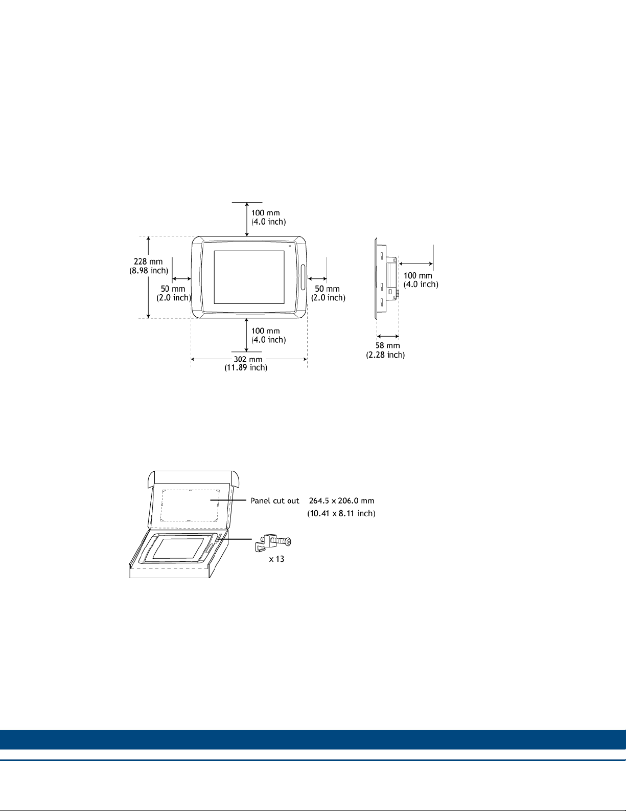
2.1 Space Requirements
Installation plate thickness: 1.5 – 9.0 mm (0.06 - 0.35 inch)
Space requirements when installing the graphic operator terminal:
Graphic Operator Terminal / INSTALLATION
CAUTION! The openings on the enclosure are for air convection. Do not cover these
openings!
2.2 Installation Process
1. Unpack and check the delivery. If damage is found, contact Kollmorgen.
WARNING! Place the graphic operator terminal on a stable surface during installation.
Dropping it or letting the terminal fall may cause damage.
7
Page 8
Graphic Operator Terminal / INSTALLATION
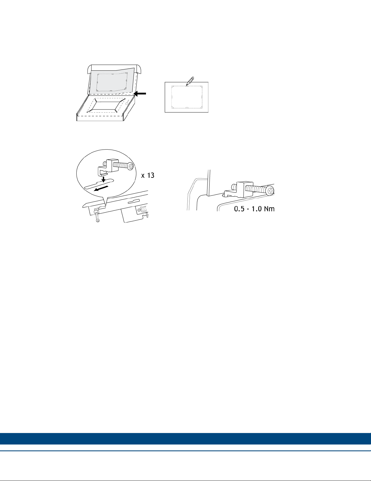
2. Place the pa
nel cut out where the graphic operator terminal is to be situated, draw along the
outer sides of the holes and cut according to the markings.
3. Secure the graphic operator terminal in position using all the fastening holes and the provided
brackets and screws:
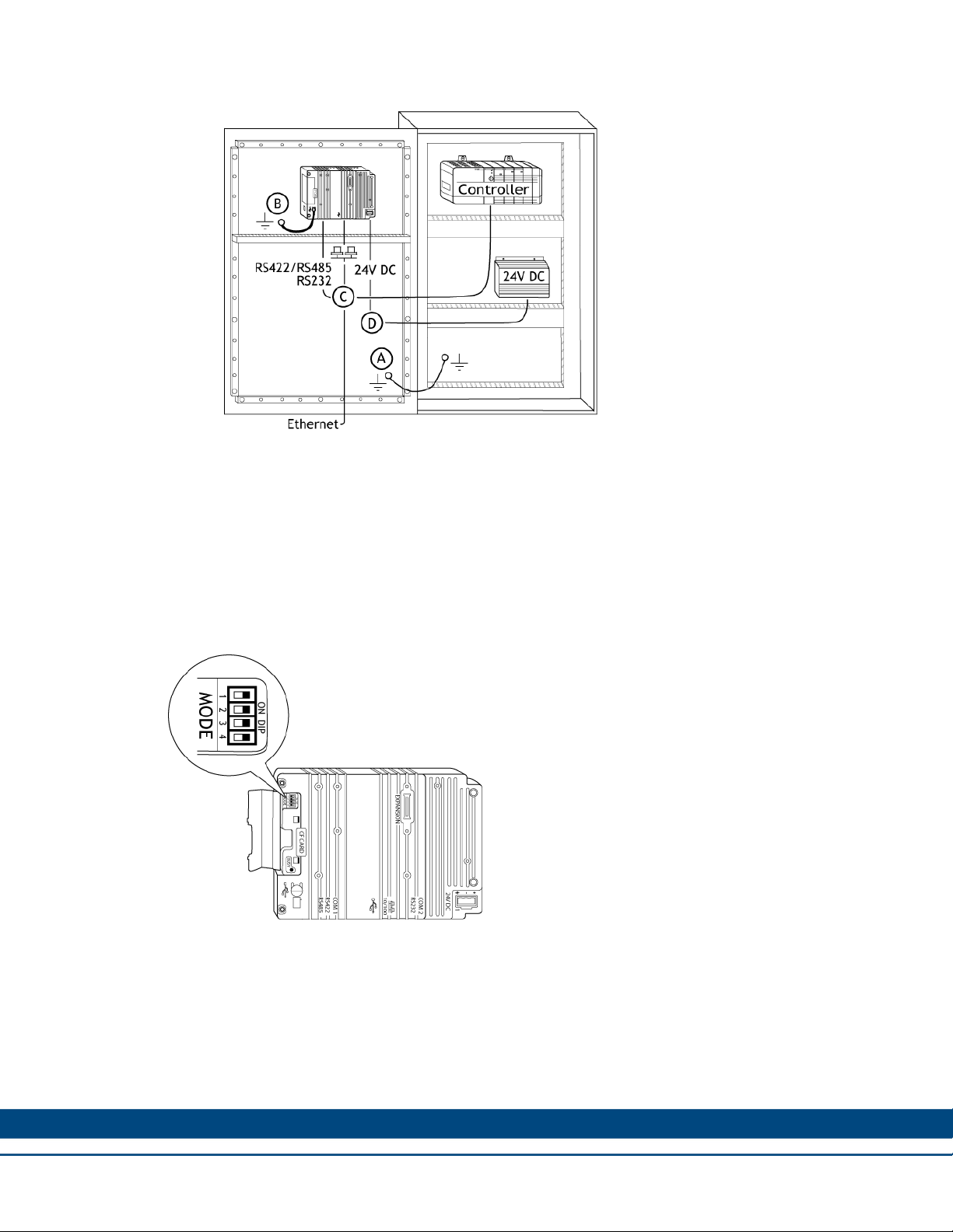
4. Connect the cables in the specified order.
A. CAUTION! Ensure that the graphic operator terminal and the controller system have the
same electrical grounding (reference voltage level), otherwise errors in communication
may occur.
B. Use an M5 screw and a grounding conductor (as short as possible) with a cross-section
of minimum 2.5 mm
2
.
C. CAUTION! Use only shielded communication cables. Separate high voltage cables from
signal and supply cables.
D. CAUTION! The graphic operator terminal must be brought to ambient temperature
before it is started. If condensation forms, ensure that the graphic operator terminal is dry
before connecting it to the power outlet. Ensure that the voltage and polarity of the power
source is correct.
8
Page 9
Graphic Operator Terminal / INSTALLATION
5. Carefully remove the laminated film over the graphic operator terminal display to avoid static
electricity that could damage the terminal.
2.2.1 Mode Switches
The HMI panels have four mode switches (DIP switches) located on the rear side of the operator
terminal.
All mode switches must be in OFF position during graphic operator terminal use. The mode
switches should not be touched unless by qualified personnel.
Changing Mode Switches
To change mode switches, follow the steps below:
1. Disconnect power from the operator panel.
2. Set the mode switches using a ballpoint pen.
3. Reconnect power to the operator panel.
9
Page 10

Graphic Operator Terminal / INSTALLATION
Modes
The mode switches have the following functions: 1 = ON, 0 = OFF.
Each letter in “MODE” has a corresponding mode switch
WARNING! The modes below are to be used with caution.
MODE Description
0000 “Run-mode” - Boot CE, normal operation.
System Restore, resets the file system and registry, reinstalls the
0010
0100
1000
system pro-gram (OPsys_bxxx.CAB). Restores the operator panel
to factory settings.
WARNING! Information can accidently be lost.
Image Load mode (Sysload) allows upgrading of the firmware in the
operator panel.
Note: All files including the file system in the operator panel are
deleted when upgrading with Image Loader.
Service Menu mode, the service menu for the system program is
shown.
Allows the user to set IP configuration, erase the project, calibrate
the touch screen, set the panel in Run/Transfer mode etc.
1100 Not used (Run-mode).
1110 Self-Test
xxx1 Hard reset (forces the system to reset).
2.2.2 Connections to the Controller
For information about the cables to be used when connecting the graphic operator terminal to the
controller, please refer to the help file for the driver in question.
2.2.3 Other Connections and Peripherals
Cables, peripheral equipment and accessories must be suitable for the application and its
environment. For further details or recommendations, contact Kollmorgen.
CAUTION! When using a compact flash card, do not remove the card when the busy indicator is
illuminated.
10
Page 11

Graphic Operator Terminal / TECHNICAL SPECIFICATIONS
3 TECHNICAL SPECIFICATIONS
This chapter provides the technical specifications for the graphic operator terminal.
3.1 Technical Data
The following table provides the electrical and mechanical specifications for the graphic operator
terminal.
Parameters AKI-CDT-MOD-10T
Front panel 302 x 228 x 6 mm (W x H x D)
Mounting depth 58 mm (158 mm including clearance)
Front panel seal IP 66
Rear panel seal IP 20
Touch screen
material
Reverse side material Powder-coated aluminum
Weight 2.1 kg
Serial port
RS422 / RS485
Serial port RS232C
Ethernet Shielded RJ 45
USB
CF-slot Compact flash, type I and II
Real time clock
Real time clock
battery
Power consumption
at rated voltage
Touch screen: Polyester on glass, 1 million finger touch
operations. Overlay: Autotex F157/F207 *.
25-pin D-sub contact, chassis-mounted female with
standard locking screws 4-40 UNC.
9-pin D-sub contact, male with standard locking screws 440 UNC.
Host type A (USB 1.1), max output current 500 mA
Device type B (USB 1.1)
±20 PPM + error because of ambient temperature and
supply voltage. Total maximum error: 1 min/month at 25 °C
Temperature coefficient: -0.034 ± 0.006 ppm/°C
Rechargeable batter
CR2450 (UL and cUL: Sanyo or Panasonic) Minimum
lifetime: 3 years
Normal: 0.5 A
Maximum: 1.0 A
2
Display
Active area of display 211.2 x 158.4 mm
Fuse Internal DC fuse, 3.15 AT, 5 x 20 mm
TFT-LCD. 800 x 600 pixels, 64K colors. CCFL backlight
lifetime at the ambient temperature of +25 °C: >50,000 h.
11
Page 12

Graphic Operator Terminal / TECHNICAL SPECIFICATIONS
Parameters AKI-CDT-MOD-10T
+24V DC (20 - 30V DC). Power supply connector.
CE: The power supply must conform with the requirements
Power supply
according to IEC 60950 and IEC 61558-2-4.
UL and cUL: The power supply must conform with the
requirements for class II power supplies.
Ambient temperature
Vertical installation: 0 ° to +50 °C
Horizontal installation: 0 ° to +40 °C
Storage temperature -20 ° to +70 °C
Relative humidity 5 - 85 % non-condensed
CE approvals
Noise tested according to EN61000-6-4 emission and
EN61000-6-2 immunity.
UL, cUL approvals
(when product or
UL 1604 Class I, Div 2 / UL 508 / UL 50 4x indoor use only
packing is marked)
DNV Yes
NEMA 4x indoor use only
* See section Chemical Resistance for more information.
12
Page 13

Graphic Operator Terminal / CHEMICAL RESISTANCE
4 CHEMICAL RESISTANCE
This chapter describes the chemical resistance for the graphic op erator terminal.
4.1 Metal Casing
The frame and casing material is powder-coated aluminum. This powde r paint withstands
exposure to the following chemicals without visible change:
Chemicals
Acetic acid 10% Phosphoric acid 4%
Citric acid 10% Phosphoric acid 10%
Diesel Sea water
Distilled water Sodium chloride 2%
Edible oil Sodium chloride 20%
Fuel oil Euphoric acid 20%
Hydrogen peroxide 3% Tap water
The powder paint shows limited resistance to the foll owing chemicals at room temperature:
Chemicals
Butanol Nitric acid 3%
Hydrochloric acid 5% Nitric acid 10%
Isopropyl alcohol Phosphoric acid 43%
Na-hypochlorite 10% Turpentine
Note: If exposure to any of the above chemicals is demanded, it is recommended to first test the
chemical on an invisible spot of the metal casing.
The powder paint shows little or no resistance to the following chemicals at room temperature:
Chemicals
Acetic acid, conc. Methyl-ethyl ketone Toluene
Acetone Nitric acid 30% Trichloroethylene
Ammonia 5% Phenol Xylene
Ammonia, conc.
Ethyl acetate Sodium hydroxide 98 octane leaded petrol
Sodium hydroxide 5% 97 octane unleaded
petrol
13
Page 14

4.2 Touch Screen and Overlay
This section provides information about the touch screen and overlay for the device.
4.3 Autotex F157/F207
Autotex F157 or F207 covers the overlay surrounding the touch screen.
Solvent Resistance
Autotex F157/F207 withstands exposure of more than 24 hours duration under DIN42 115 Part 2
to the following chemicals without visible change:
Chemicals
Acetonitrile Diesel Downey / Lenor1 Phosphoric acid (<30%)
Ajax / Vim in solution Ethanol Potassium ferricyanide
Graphic Operator Terminal / CHEMICAL RESISTANCE
Alkali carbonate solution1
Ammonia (<40%)1 Glycol Pure turpentine
Acetic acid (<50%) Gumption1 SBP 60 / 951
Ariel powder in solution1 Hydrochloric acid (<36%) Sulfuric acid (<10%)
Bleach1 Linseed oil Tomato ketchup
Castor oil
Caustic soda (<40%)1 Nitric acid (<10%) White spirit
Cutting oil Paraffin oil Windex1
Cyclohexanol Persil powder in solution1 Wisk
Diacetone alcohol Petroleum spirit1
1
Extremely faint glossing of the texture was noted.
Autotex withstands DIN 42 115 Part 2 exposure of up to 1 hour duration to glacial acetic acid
without visible change.
Autotex is not resistant to high pressure steam at over 100 °C or the following chemicals:
Glycerin Potassium hydroxide
(<30%)
Methanol Tricjloroacetic acid
(<50%)
Chemicals
Concentrated mineral acids Benzyl alcohol
Concentrated caustic solution Methylene chloride
Outdoor Use
In common with all polyester based films Autotex F157/F207 is not suitable for use in conditions
of long term exposure to direct sunlight.
14
Page 15

4.4 Touch Screen Surface
The touch screen surface on the terminal withstands exposure to the following solvents without
visible change:
Solvents Time
Acetone 10 minutes
Isopropanol 10 minutes
Toluene 5 hours
4.5 Touch Screen Protector
It is recommended to use the Touch Screen Protector film that can be ordered from Kollmorgen.
Solvent Resistance
The Touch Screen Protector film withstands exposure to the same chemicals as Autotex F157 or
F207 according to section Autotex F157/F207.
Graphic Operator Terminal / CHEMICAL RESISTANCE
Outdoor Use
In common with all polyester based films, Touch Screen Protector film is not suitable for use in
conditions of long term exposure to direct sunlight.
15
Page 16

Graphic Operator Terminal / OPERATOR TERMINAL DIAGRAMS
5 OPERATOR TERMINAL DIAGRAMS
This chapter provides the operator terminal diagrams.
5.1 Communication Port Diagrams
16
Page 17

5.2 Outline Diagrams
Graphic Operator Terminal / OPERATOR TERMINAL DIAGRAMS
17
Page 18

6 INSTALLATION TIPS
When experiencing communication problems in noisy environments or when operating close to
temperature limits, observe the following recommendations.
6.1 Grounding the Operator Terminal
Graphic Operator Terminal / INSTALLATION TIPS
The graphic operator terminal’s mounting clamps do not provide a secure grounding
connection between the terminal and the device cabinet.
2
Connect a 2.5 mm
terminal chassis.
Connect a 6 or 4 mm
grounding point on the door.
Connect a strong but short grounding braid between the door and the device cabinet.
Twist the cables onto the 24 V DC feed.
A ferrite core suppresses disturbances to the 24 V feed:
– Two turns around the ferrite core provide four times the suppression of one turn.
– Three turns around the ferrite core provide nine times the suppression of one turn.
wire between the graphic operator terminal’s quick-connect plinth and the
2
wire or grounding braid between the terminal’s chassis and the closest
18
Page 19

Note
: The grounding wires should be short and the conductor should have a large area. A
long, thin grounding wire has very high impedance (resistance) at high frequencies and will
not guide disturbances to the ground. Multi-wire conductors are better than single wire
conductors with the same area. A braided conductor wire with the same area is better. The
best is a short, thick grounding braid.
6.2 Ethernet Connection in the Terminal
Graphic Operator Terminal / INSTALLATION TIPS
In some industrial units for Ethernet, the RJ45 contact’s shield is co nnected to the chassis via
a capacitor.
The graphic operator terminal’s Ethernet shield is directly connected to the chas sis.
Check whether the other Ethernet unit has its shield directly grounded or grounded via a
capacitor.
In many cases, connecting the shielded Ethernet cabling to the chassis at both ends is
inappropriate. Hum or grounding loops can occur. Unshielded cabling may even result in
fewer communication errors.
As a solution, use a shielded Ethernet cable. However, only connect the shield at one end.
A possible option is to break the shield.
Another option is to expand the shielded Ethernet cabling with a piece of unshielded Ethernet
cable.
You can ground the shield via an external 0.1 uF/250 V plastic capacitor. This will connect
the HF transients to the ground.
19
Page 20

6.3 Achieving EMC Protection
The following suggestions should be taken into consideration to achieve better EMC protection:
Initially, use the original cabling from Kollmorgen primarily.
Use shielded cables for RS232 communication.
Use twisted pair and shielded cabling for RS422 and RS485.
Use the cabling intended for the bus type; Ethernet, Profibus, CC-Link, CAN, Device Net etc.
Install and connect according to applicable specifications for the relevant bus standard.
Use shielded cabling for Ethernet, preferably with foil + braided shield.
D-sub covers should be shielded and the shield should be connected to the cover 360 °
where the cable comes in.
Connect the shield at both ends.
Graphic Operator Terminal / INSTALLATION TIPS
With longer distances, there is a risk that the ground potential may be different. In this scenario,
the shield should only be connected at one end. A preferred alternative is to connect the other
end of the shield to the ground via a 0.1 uF/250 V plastic capacitor. Both ends are then
connected to the ground in terms of HF, but only connected to the ground at one end in terms of
LF, thus avoiding the 50 Hz grounding loops.
20
Page 21

Graphic Operator Terminal / INSTALLATION TIPS
Use an EMC cabl
e gland or regular plastic cable gland. Remove the outer jacket and connect the
shield to the installation plate with a 360 ° metal cable clamp.
Place the 24 V DC and communications cabling in one cable trunk/cable du ct and 230/380 V AC
in another. If the cables need to be crossed, cross them at 90 ° only. Avoid combining the cabling
for stronger 24 V DC outputs with the communication cabling.
Ferrite cores that are snapped onto the shielded cabling may remove minor disturbances. Large
ferrite pieces that are snapped onto unshielded cabling and where the wires go 2-4 times around
the cores are approximately 5-25 times more efficient.
6.4 Ambient Temperature
The maximum ambient temperature for the graphic operator terminal is provided in the
specifications. The ambient temperature refers to the temperature in the device cabinet which
cools the terminal’s electronics.
In most cases, the ambient temperature for the graphic operator terminal is signif icantly higher
than the device cabinet’s ambient temperature.
If the cabinet is tall and there are a number of heat-generating devices, the temperature at the top
of the cabinet is considerably higher than the theoretical temperature increase that is expected.
All electronics are sensitive to heat. The lifespan of an electrolytic capacitor is cut in half with an
8-10 ° increase in temperature. A 15-20 ° temperature increase results in a quarter of the lifespan
etc.
2
Note: An enamel-coated steel cabinet has a radiant heat value of 5.5 W/m
and degrees C.
Installing a fan inside the cabinet will even out the temperature, while moving air provides
considerably better cooling than still air. A suitable fan is a 120 x 120 mm axial fan, available in
24 V DC, 115, and 230 V AC.
21
Page 22

Graphic Operator Terminal / INSTALLATION TIPS
Install the fan so that it sits in the cool
terminal. If the fan is mounted at the top and sucks air upwards, the fan’s ambient temperature is
higher resulting in a shorter lifespan.
A good fan with a ball-bearing mounting has an expected lifespan of at least 40,000 hours (not a
guaranteed lifespan) at 40 °C. This corresponds to at least 4 years of continuous use. If a
thermostat is installed, the fan only needs to come on when needed.
Large graphic terminals draw only one fifth of the current when the background lighting is off. The
loss effect drops from e.g. 25 W to only 5 W. The graphic operator terminal’s loss effect = supply
voltage x current. Virtually no power goes to external users and no loss effects due to inputs.
6.5 Safety
Most of the graphic operator terminals are powered with 24 V DC.
er area and blows cold air against the graphic operator
If you use a power supply that meets safety standards and only supplies the graphic operator
terminal, no problems should occur. However, use caution if you have a 24 V unit that also
supplies other units.
22
Page 23

Graphic Operator Terminal / INSTALLATION TIPS
WARN
requirements in the event of a potential short circuit between 230 V AC and 24 V DC. It is
assumed that the 24 V feed is secure. For example, SELV according to EN 60950 (protection
against electric shock) and UL 950.
Example: This example explains why a secure 24 V DC feed can be ruined by mixing 24 V relay
contacts with 230 V AC relay contacts in a smaller controller. Check that the clearances and
creep age distances between 24 V DC and 230 V AC fulfill EN 60950 or UL 950. If not, input a
separate 24 V unit into the graphic operator terminal.
If there is a substantial distance between the relay contacts for 24 V DC and 230 V AC, it is
Connect 0 V on the 24 V feed to the ground. This offers three advantages:
ING! The graphic operator terminal does not have insulation that meets safety
safe to use the same 24 V devices for all feeds.
– Safety is increased. The 24 V feed will not be live in the event of a faulty connection or
short circuit between 0 V (24 V) and 230 V phase.
– Transients on the 24 V feed are connected to the ground.
– No risk that the 24 V feed is at a high level in relationship to the ground. This is not
unusual since there is high static electricity.
6.6 Galvanic Isolation
The graphic operator terminal has galvanic isolation against the 24 V DC feed but no galvanic
isolation between the communication ports for RS232, RS422/485 and USB. Only the Ethernet
connection isolation has galvanic isolation.
When a PC is connected to the terminal, the terminal’s internal 0 V (GND) is connected to the
protective ground via the PC.
A number of USB devices can have the shield connected together with the protective ground.
Here, the terminal’s 0 V (GND) is connected to the protective ground. For example, a USB
memory stick, keyboard or similar device is plugged in.
23
Page 24

If a number of units are connected have a 0 V and a ground connection, and these units are
connected to various grounding points, there is a substantial risk of problems. Gr ounding currents
go through communication cables, the rear plate of the controller, and internally in the graphi c
operator terminal, and can cause errors.
Note: It is important to make sure that the 24 V feed in the external insulation unit is not
connected to one of the communication outlets. If it does not have 100% insulation against the 24
V feed, disturbances and grounding currents from the 0 V on the 24 V side will disrupt
communication.
Using this type of unit solves one problem but may create a larger problem! A substandard
installation may work now, but problems may arise when other devices are connected.
6.7 Cable and Bus Termination RS485
Use shielded and twisted pair cable.
The pair capacitance may not exceed 52.5 pF/m and area at least 0.25 mm
want to use the maximum transfer distance and maximum transfer speed.
0 V, the reference voltage for communication should be included in the cabling. With two-way
communication use two pairs; one pair for communication and one pair for 0 V.
The shield must be grounded at one end. The other end is usually grou nded, but with longer
distances or when there is a difference in the ground potential, the shield should be
connected to the ground via 0.1 uF/250 V plastic capacitor to prevent ground current in the
braided shield.
Graphic Operator Terminal / INSTALLATION TIPS
2
(AWG 24), if you
A number of manufacturers recommend that the shield be grounded at each node. Various
manufacturers have different systems for bus termination. The RS485 standard does not describe
how the Fail Safe function is carried out, just that the system should be able to handle the error.
Depending on the recipients’ design, the bus wires may be on the same level or re quire pull-up or
pull-down to ensure that no faulty signals are detected when the bus is in resting mode (all
transmitters are disconnected).
24
Page 25

APPENDIX A
This section provides the mechanical drawings of the AKI-CDT-MOD-10T 10.4" Touch s creen
HMI.
A.1 AKI-CDT-MOD-10T 10.4” – Front View 1
Graphic Operator Terminal / APPENDIX A
302 mm
228 mm
A.2 AKI-CDT-MOD-10T 10.4” – Front View 2
12 (0.47) mm
PANEL CUT OUT FOR 10.4" Touch
Front view
SCALE 1:1
Terminal center
264,5±1 (10.4±0.04)
Cut out
Terminal outline
206±1 (8.1±0.04)
24,25 (0.95) mm13,25 (0.52) mm
10 (0.39) mm
25
Page 26

A.3 AKI-CDT-MOD-10T 10.4” – Bottom View
24 VDC
COM2
RS232
Ethernet
A.4 AKI-CDT-MOD-10T 10.4” – Side View
Graphic Operator Terminal / APPENDIX A
COM1
RS422/485
USB Device
6 mm
58 mm
max 9 mm material thickness
CF
USB Host
26
Page 27

A.5 AKI-CDT-MOD-10T 10.4” – Back View
Graphic Operator Terminal / APPENDIX A
25 mm
13 mm
204 mm
263 mm
14 mm
11 mm
27
Page 28

About Kollmorgen
Kollmorgen is a leading provider of motion systems and
components for machine builders. Through world-class
knowledge in motion, industry-leading quality and
deep expertise in linking and integrating standard and
custom products, Kollmorgen delivers breakthrough
solutions that are unmatched in performance, reliability
and ease-of-use, giving machine builders an irrefutable
marketplace advantage.
For assistance with your application needs, contact
us at: 540-633-3545, contactus@kollmorgen.com
or visit www.kollmorgen.com
North America
Kollmorgen
203A West Rock Road
Radford, VA 24141 USA
Phone: 1-540-633-3545
Fax: 1-540-639-4162
Europe
Kollmorgen
Wacholderstraße 40 – 42
40489 Düsseldorf Germany
Phone: + 49 (0) 2039979235
Fax: + 49 (0) 20399793314
 Loading...