

Page 1

Graphic Operator Terminal
Installation
Manual
ion B, October 2014
Edit
AKI-CDC-MOD-12T 12.1” Touchscreen HMI
Keep all manuals as a product component during the life span of the product.
Pass all manuals to future users / owners of the product.
Page 2

Record of Document Revisions
Revision Remarks
A, 07/2013
Preliminary edition
B, 10/2014 Updated UL information
Hardware Revision
Revision Firmware revision Softwarerevision Remarks
06/2013 2.0-SP1
10/2014
IMPORTA
Technicalchanges which improve the performance of the device may be made without prior notice!
Printed in the Un ited States of America. This document is the intellectual property of Kollmorgen™. All rights reserved. No
part of this w ork may be reproduc ed in any form (by photocopying, microfilmor any other method) or stored, processed,
copied or distributed by electronic means without the writtenpermission of Kollmorgen™.
b1.2.0.3 2.10
NT NOTICE
Initial release
ky
Kollmorgen | October 2014
2
Page 3

AKI-CDC-MOD-12T | CONTENTS
1 General
1.1 AboutThis M
2 SafetyPrecau
anual .......................................................................
tions
2.1 General ................................................................................... 5
2.2 UL and cUL I
2.3 DuringIns
2.4 During Use
2.5 Service an
2.6 Dismantl
2.7 Appearan
3Installati
on
3.1 Space Req
3.2 Install
3.2.1 Conne
3.2.2 Other
4 Hardware R
4.1 Replac
4.2 Replac
4.3 Replac
4.4 Replac
5 Technica
6Chemica
lData
lResistance
6.1 Metal
6.2 Touch
6.2.1 Aut
6.2.2 To
6.2.3 To
7Operat
or Panel Drawings
7.1 Conn
ectors ...............................................................................
7.2 Comm
7.3 AKI
8Addit
8.1 Gro
8.2 Eth
8.3 To A
8.4 Am
8.5 Sa
8.6 Ga
8.7 Ca
8.8 Bo
8.9 E
8.10
-CDC-MOD-12T Outline ............................................................
ional InstallationTips
undingtheOperatorPanel ..........................................................
ernet Connectionin theOperatorPanel ............................................
chieveBetterEMC Protection ......................................................
bient Temperature ....................................................................
fety .....................................................................................
lvanicIsolation ........................................................................
bleandBusTermination RS485 .....................................................
ot Priority ..............................................................................
nteringBIOS ............................................................................
Reset Switch ............................................................................
nstallation ..................................................................
tallation ........................................................................
................................................................................
dMaintenance ...............................................................
ingandScrapping ..............................................................
ce of Airin TouchScreen .....................................................
uirements ....................................................................
ation Process ......................................................................
ctionsto theController ...................................................
ConnectionsandPeripherals ............................................
eplacement
ingtheFanandFilter .............................................................
ingthe2.5”SATA Mass Storage ................................................
ingaCompactFlashor CFastMemoryCard ...................................
ingtheBattery ....................................................................
Casing .............................................................................
ScreenandOverlay ..............................................................
otexF157/207 ................................................................
uchScreen Surface ...........................................................
uchKeyboardandScreen Protection Film ...................................
unicationPorts ....................................................................
4
5
6
7
7
7
7
8
9
11
11
12
15
17
18
21
22
22
22
23
24
24
25
26
27
28
29
30
31
31
32
32
32
ky
Kollmorgen | October 2014
3
Page 4

1 GENERAL
1.1 About This Manual
All Advanced Kollmorgen Interfaces are developed to satisfy the demands of human-machine
communication. Built-in fu nctionssuch as displaying and controlling text, dynamicindication, time
channels, alarm and recipe handling are included.
The Advanced Kollmorgen Interfaces works primarily in an object-oriented way, making it easy to
understand and use. Configuration is carried out on a PC using the Kollmorgen Visualization Builder
configuration tool. The project can then be transferred and stored in the operator panel itself.
Various types of automation equipment such as PLCs, servos or drives can be connected to the
Advanced Kollmorgen Interfaces. In this manual, the term “the controller” refers to the connected
equipment.
This manual explains how to install the operator panel. Pleaserefer to the Kollmorgen Visualization Builder Programming and Installation manual for further information.
AKI-CDC-MOD-12T | GE NERA L
ky
Kollmorgen | October 2014
4
Page 5

2 SAFETY PRECAUTIONS
Both the installer and the owner and/or operator of the operator panel must read and understand
this installation manual.
2.1 General
• Read the safety precautions carefully.
• Check the delivery for transportation damage. If damage is found, notify the supplier as soon as
possible.
• The supplier is not responsible for modified, altered or reconstructed equipment.
• Use only parts and accessories manufactured according to specifications of the supplier.
• Read the installation and operating instructions carefully before installing, using or repairing
the HMI panel.
• Never allow fluids, metal filings or wiring debris to enter any openings in the HMI panel. This may
cause fire or electrical shock.
•Onlyqualified personnel may operate the HMI panel.
• Storing the HMI panel where the temperature is lower/higher than recommended in this manual
can cause the LCD display liquid to congeal/become isotopic.
• The LCD display liquid contains a powerful irritant. In case of skin contact, wash immediately
with plenty of water. Incase of eye contact, hold the eye open, flushwith plenty of water and get
medical attention.
•Thefigures in this manua l serves a n illustrative purpose. Because of the many variables
associated with any particular installation, the supplier cannot assumeresponsibility for actual
use based on the figures.
• The supplier neither guarantees that the HMI panel is suitable for your particular application, nor
assumes responsibility for your product des ign,installation or operation.
• It is r ecommended to turn on and shut down the HMI panel at least o nc e before installing any
components/cards or before connecting the operator panel to external devices, like for example
serial devices.
AKI-CDC-MOD-12T | SAFETY PRECAUTIONS
2.2 UL and cUL Installation
•Thise
•Allde
Do not disconnect equipment unless power has been removed or the area is known to be
non-hazardous
AVANT DE DECONNECTER L’EQUIPEMENT, COU PER LE COURANT
OUS’ASSURER QUE L‘EMPLACEMENT EST DESIGNE NON DANGEREUX.
Only UL and cUL approved expansion units are allowed to be connected to the port designated
“EXPANSION”. Atthe moment there are no such units evaluated or allowed.
SEULES LES UNITÉS D'EXTENSION CERTIFIÉES UL ET
cUL PEUVENT ÊTRE RACCORDÉES AU PORT DÉSIGNÉ « EXPANSION».
À L'HEURE A CTUELLE, AUCUNE U NITÉ DE CE TYPE N'A ÉTÉ TESTÉE
OU AUTORISÉE.
quipment is suitable for u se in Class 2 non-hazardous locations only. [Combinations of
ment in your system are subject to investigation by the local authority having jurisdiction
equip
time of installation].
at the
vices have to be supplied by a Class 2 power supply.
ky
Kollmorgen | October 2014
5
Page 6
AKI-CDC-MOD-12T | SAFETY PRECAUTIONS
Do not replace expansion unit unless power has been switched off or the area is known to
be non-hazardous.
NE REMPLACEZ L'UNITÉ D'EXTENSION QUE SI LE
COURANT A ÉTÉ COUPÉ OU SI LA ZONE EST JUGÉE NON DANGEREUSE.
• This product contains a battery; this must only be changed in an area known to be non-hazardous.
• Replace the battery with a BR 2032 battery. Use of another type of battery may present a risk of
fire or explosion.
Battery may
LA BATTERIE
NE LA RECHA
PAS DANS LE
explode if mistreated. Do not recharge, disassemble or dispose of in fire.
PEUT EXPLOSER EN CAS DE MAUVAISEMANIPULATION.
RGEZ PAS,NE LA DÉMONTEZ PASETNE LA JETEZ
FEU.
• For use on a flat surface of a type 4X enclosure indoor use only.
• Use minimum 75°C copper conductors only.
• To make wiring connections to the power supply connector, follow the table with cable and torque
specifications below:
Terminal Block Connector Wire Size TQ Lb.In.
X1/X100 Phoenix connectors AWG30–12
X1/X10
0 Anytek connectors
AWG 24–
12
5–7
3.5
• These devices are Class 2 supplied programmable controllers (industrial PCs) for the use in
industrialcontrol equipment and are intended to be (front) panel mounted (Type1 and 4x for
indoor use only).
Caution:
The enclosure provides a degree of protection of at least IP20, but when installed in an
apparatus,it should meet IP54.
LE BOÎTIER OFFR E UN DEGRÉ DE PROTECTION D'AU MOINS IP20, MAIS
LORSQU'IL EST IN STALLÉ DANS UN APPAREIL,ILDOIT ÊTRE DE CLASSE IP54.
2.3 During Installation
• The HMI panel is designed for stationary installation on a plane surface, where the following
conditions are fulfilled:
– no high explosive risks
– no strongmagnetic fields
– no directsunlight
– no large, sudden temperature changes
• Install the HMI panel according to the accompanying installation instructions.
• Ground the HMI panel according to the accompanying installation instructions.
•Onlyqualified personnel may install the HMI panel.
• Separate the high voltage, signal and supply cables.
ky
Kollmorgen | October 2014
6
Page 7

• Make sure that the voltage and polarity of the power source is correct before connecting the HMI
• Peripheral equipment must be appropriate for the application and location.
2.4 During Use
AKI-CDC-MOD-12T | SAFETY PRECAUTIONS
panel to the power outlet.
• Keep the HMI p
• Emergency st
• Do not use exc
2.5 Service and
•Onlyqualified personnel should carry out repairs.
• The agreed warranty applies.
• Before carrying out any cleaning or maintenance operations, disconnect the equipment from
• Clean the display and surrounding front cover with a soft cloth and mild detergent.
• Replacing the battery incorrectly may result in explosion. Onlyuse batteries recommended
• The unit can be reset by using the reset switch located behind the fan.
Maintenance
the electrical supply.
by the supplier. Duringthewarranty period, the battery needs to be replaced by an authorized
Kollmorgen service center.
anel clean.
op and other safety functions may not be controlled from the HMI panel.
essive force or sharp objects when operating the touchscreen.
2.6 Dismantling and Scrapping
• The HMI panel or parts thereof shall be recycled according to local regulations.
• The following components contain substances that might be hazardous to health and the
environment: lithiumbattery, electrolytic capacitor and display.
2.7 Appearance of Air in TouchScreen
The lay
arise.
can occ
pressu
er structure of the touch screen contains air and in rare cases appearance of bubbles can
This is purely cosmetic and does not affect any functionality of the HMI panel. The appearance
ur under certain environmental conditions such as temperature, humidity,andatmospheric
re.
ky
Kollmorgen | October 2014
7
Page 8
3INSTALLATION
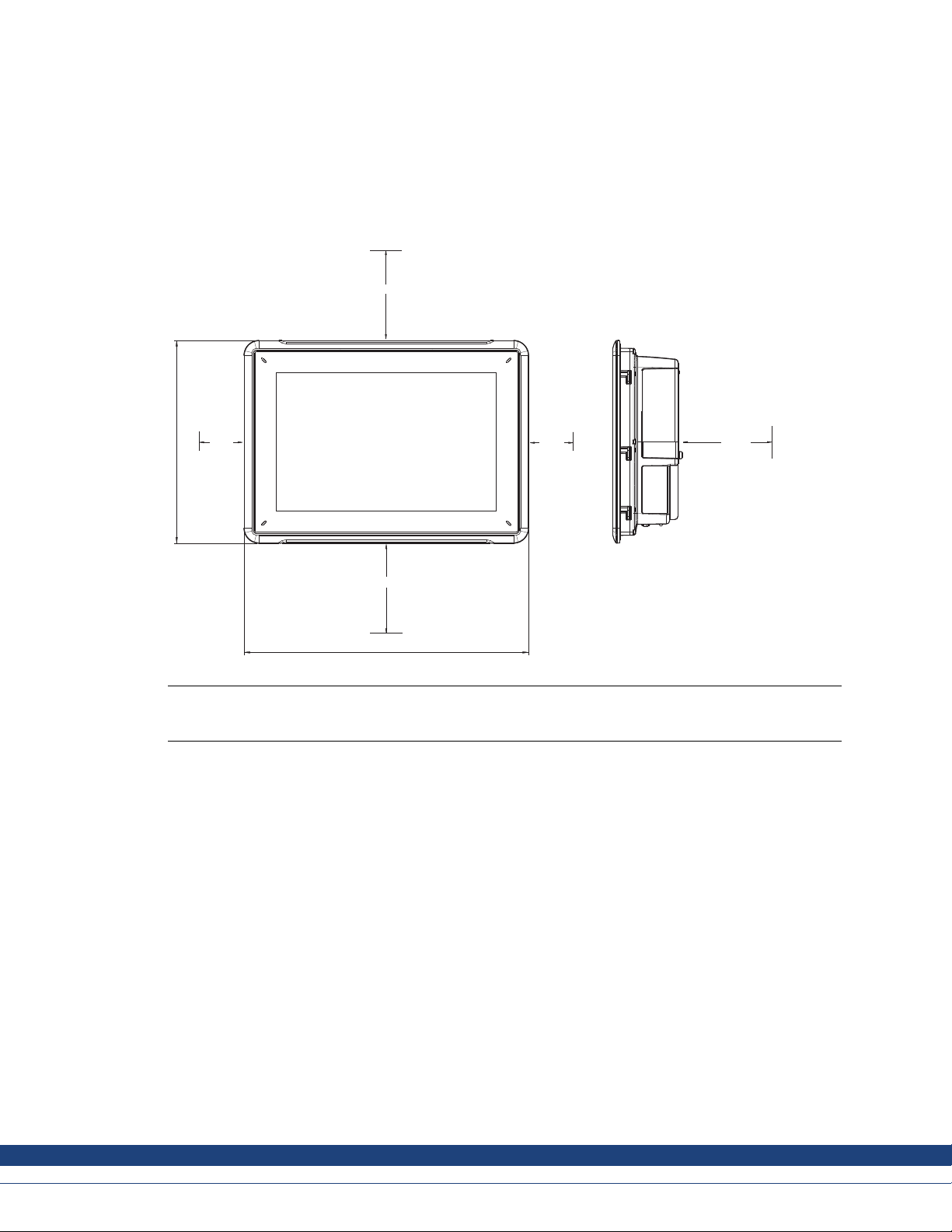
3.1 Space Requirements
• Maximum installation plate thickness: 8 mm
• Space requireme n ts in millim eters when installing the operator panel:
AKI-CDC-MOD-12T | INSTALLATION
100 mm
242,2 mm
50 mm
50 mm
100 mm
340 mm
100 mm
Note:
mensions on the drawingare not proportional.
The di
Caution:
The openings on the enclosure are for air convection. Do not cover these openings.
ky
Kollmorgen | October 2014
8
Page 9
3.2 Installation Process
AKI-CDC-MOD-12T | INSTALLATION
The following
is needed:
• A Torx TX7 screwdriver
1.
Unpack and che
Note:
Place the HMI panel on a stable s urface during installation.
Dropping the HMI panel or letting it fall may causedamage.
2.
To cut a correct opening for the HMI panel, use the cut out dimensions in the outline drawing. For
ck the delivery. If damage is found, notify the supplier.
more information, see sections Operator Panel Drawings and TechnicalData.
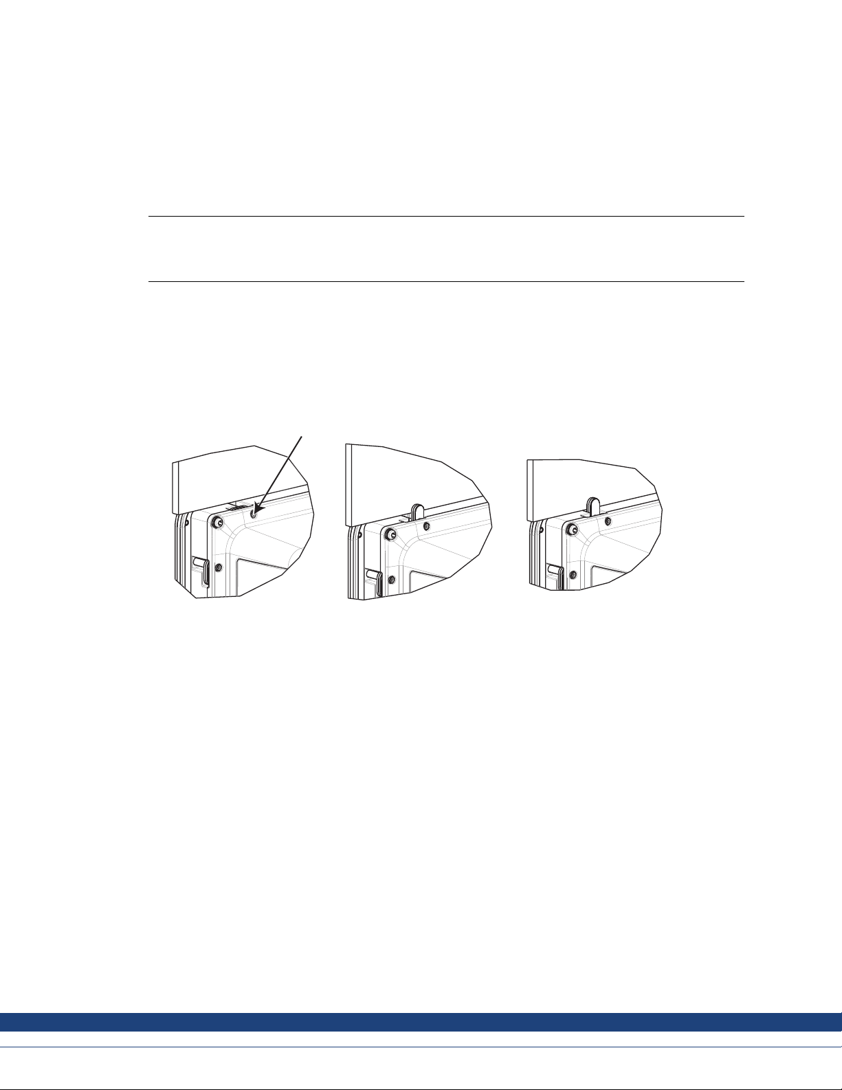
3.
Secure the
tighten a
HMI panel in positio n by s crewingthe M4 Torxscrew,allowing the built-in bracket to
gainst the panel:
M4 x 20.7
0.4 Nm
Figure 3-1: A.M4 x 20.7, 0.4 Nm
ky
Kollmorgen | October 2014
9
Page 10
AKI-CDC-MOD-12T | INSTALLATION
4.
Connect the cab
les in the specified order, according to the drawing and steps below.
Caution:
The HMI panel must be brought to ambient temperature before it is started up. If condensation forms, ensure
•
that the HMI panel is dry before connecting it to the poweroutlet.
• Ensure that the HMI panel and the controller system have the same electrical grounding (reference voltage
level), otherwise errors in communication may occur.
• Ensure that the voltage and polarity of the power sou rce is correct.
• Separate high voltage cables from signalandsupply cables.
• Shielded communication cables are recommended.
B
RS232/
RS422/
RS485
24V DC
C
Power
Controller
24V DC
D
A
Ethernet
– Connect cable A.
– Connect cable B, using an M5 screw and a grounding conductor (as short as possible), that is
sized correctly according to local electrical codes.
– Connect cable C.
– Connect cable D. The recommended cross-section of the cable is 2.5 mm
5.
Carefully remove the lam inatedfilm over the HMI panel display,to avoid static electricity that could
2
.
damage the panel.
ky
Kollmorgen | October 2014
10
Page 11

3.2.1 Connections to the Controller
AKI-CDC-MOD-12T | INSTALLATION
For informati
refer to the he
on about the cables to be used when connecting the HMI panel to the controller,please
lp file for the driver in question.
3.2.2 Other Connections and Peripherals
Cables, peripheral equipment and accessories must be suitable for the application and its
environment. Forfurtherdetails or recommendations, please refer to the supplier.
ky
Kollmorgen | October 2014
11
Page 12

4 HARDWARE REPLACEMENT
This section contains instructions on how to replace operator panel hardware. Only components
included in the latest bill of material and spare parts list are allowed.
4.1 Replacing the Fan and Filter
The following is needed:
• A new fan
• A Torx TX10 and a TX20 screwdriver
Note:
Make sure to use adequate ESD protection.
Follow the steps below to replace the fan and fan filter:
1.
Power off the operator panel.
2.
Remove the fan lid by removing the two M3x6 Torx screws.
AKI-CDC-MOD-12T | HARDWARE REPLACEMENT
ky
Kollmorgen | October 2014
12
Page 13

AKI-CDC-MOD-12T | HARDWARE REPLACEMENT
3.
Remove the fan fi
lter.
Figure 4-1: A.Screw,M3x6 Torx
B. Fan lid
C. Fan filter
ky
Kollmorgen | October 2014
13
Page 14

AKI-CDC-MOD-12T | HARDWARE REPLACEMENT
4.
Remove the fan b
y removing the two M4x35 Torx screws.
Figure 4-2: A.Screw,M4x35 Torx
B. Fan
5.
Reassemble with new fan and filter in reverse order. Use a maximum torque of 0.4 Nm when
fastening the fan screws.
ky
Kollmorgen | October 2014
14
Page 15

4.2 Replacing the 2.5” SATA Mass Storage
AKI-CDC-MOD-12T | HARDWARE REPLACEMENT
The following
is needed:
• A new 2.5” SATAmassstorage
• A TX10 Torxscrewdriver
Note:
Make sure to use adequate ESD protection.
Follow the steps below to replace the 2.5” SATAmassstorage:
1.
Power off the operator panel.
2.
Remove the front frame assembly by removing the eight M3x8 Torx screws on the back cover
assembly.
Caution:
During disassembly, it is important to take care of the cable between the front and the rear
part. Ifyou disconnect a cable, be sure that the right cable will be in the right position when
assembling.
Note:
The exchange of electroniccomponents is only for experienced professionals.
Incorrecthandling of electronic components or cables plugged in wrong, can lead to the
destructionof the device.
3.
Remove the four M3x4 Torx screws on the two hard drive brackets. Remove the two hard drive
brackets.
4.
Remove the two M3x6 Torx screws that are securing the brackets to the CPU board.
ky
Kollmorgen | October 2014
15
Page 16

AKI-CDC-MOD-12T | HARDWARE REPLACEMENT
5.
Remove the hard disk drive from the hard drive connection on the CPU board.
6. Reassemble with the new hard disk drive in reverse order.
Figure 4-3: 1. 2.5” SATA mass storage
2. CompactFlashslot
3. CFastslot
ky
Kollmorgen | October 2014
16
Page 17

4.3 Replacing a CompactFlash or CFast Memory Card
AKI-CDC-MOD-12T | HARDWARE REPLACEMENT
The following
is needed:
• A new CompactFlash or CFast memory card.
• A TX10 Torxscrewdriver
Note:
Make sure to use adequate ESD protection.
Follow the steps below to replace a memory card:
1.
Power off the operator panel.
2.
Follow the instructions in chapter Replacing the 2.5” SATAMass Storage to remove the front
frame assembly.
3.
Install the new mem ory card in its intended slot illustrated in figure below.
Figure 4-4: 1. 2.5” SATA mass storag e
2. CompactFlash slot
3. CFast slot
4. Re
assemble in reverse orde r.
ky
Kollmorgen | October 2014
17
Page 18

4.4 Replacing the Battery
AKI-CDC-MOD-12T | HARDWARE REPLACEMENT
The following
is needed:
• A new BR 2032 (or CR 2032) battery.
• A Torx screwdriver
Note:
Make sure to use adequate ESD protection.
Follow the steps below to replace the battery:
1.
Power off the operator panel.
2.
Follow the instructions in chapter Replacing the Fan and Filter to remove the fan and access the
battery.
3. Replace th
ebattery.
4. Reassemble in reverse order.
Figure 4-5: 1. Screw M4x35 Torx
2. Fan
3. Battery
ky
Kollmorgen | October 2014
18
Page 19

5 TECHNICAL DATA
Parameter AKI-CDC-MOD-12T
Front panel,
W×H×D
Cut out dimensions,
W×H
Mounting de
Standalon
mounting
Front panel seal IP 65
Rear panel seal IP 20
Touch screen
material
Touch screen
operations
Revers
materi
Frame material Powder-coated aluminum
Weight 4.2 kg
Serial port for
COM1 RS232 and
COM2
RS422/RS485
Serial port for
COM3 RS232 and
COM4
RS422/RS485
ernet
Eth
B
US
ocessor
Pr
External storage
media
Memory RAM 2 GB* / 4 GB* DDR-3 SO-DIMM 1333 MHz
LED 1 × multi-color
Real time clock Yes (on chip)
Battery Lithium battery type BR 2032 (or CR 2032), exchangeable
Power consumption
at rated voltage
pth
e
eside
al
340 × 242 × 79 mm
324 × 226 mm
72 mm (172 mm
VESA 100 × 1
Note: Maxi
may lead to
Polyester on glass, resistive.
Overlay: Autotex F157 or F207
1 million finge r touch operations
Powder
9-pin D-sub contact with RS232 RTS/CTS, chassis-mountedfemale with standard
locking screws 4-40 UNC
Note: RS422Interface is not available yet.
9-pin D-sub contact with RS232 RTS/CTS, chassis-mountedfemale with standard
locking screws 4-40 UNC
Note: RS422Interface is not available yet.
2×1
4×
tel® Celeron® B810E (2 × 1.6 GHz), 2 MB L2 Cache, Intel® QM67 Chipset
In
Op
QM
Op
MB L2 Cache, QM67 Chipset
6
via USB
*depending on Processor Module
107 W
AKI-CDC-MOD-12T | TECHNICAL DATA
including clearance)
00
mum screw length for VESA mounting is 5.5 mm. Usage of longer screws
damage.
(1)
.
-coated aluminum
0/100/1000 Base-T (shielded RJ45)
USB Host 2.0, max output current 500 mA
tional: Intel®Core™ i3 2310E (2 × 2.1 GHz) (Hyperthreading),3 MB L2 Cache,
67 Chipset
tional: Intel®Core™ i7 2715QE (4 × 2.1 GHz) (Turbo 2.0, Hyperthreading),
ky
Kollmorgen | October 2014
19
Page 20

AKI-CDC-MOD-12T | TECHNICAL DATA
Parameter AKI-CDC-MOD-12T
Fuse 10 A
Power supply DC input range: 18 V DC to 32 V DC (140 W) ATX standard
CE: The power supply must conform with the requirements according to IEC 60950
and IEC 61558-2-4.
UL and cUL: T he power supply must conform with the requirements for class II power
supplies.
Display TFT-LCD with LED backlight. 1280 × 800 pixels, 16.7 million colors
VGA 1× VGA: resolution max. 2048 × 1 536@75Hz
DVI 1 × DVI-D sin gleLink: Resol utionmax. 1600×1200 or 1920 × 1200 (with reduced
blanking)
Activeare
display, W
Operating
temperature
Storage temperature -20 °C to +70 °C
Relative humidity in
operation
UL appro
aof
val
261.12 × 16
×H
0°Cto+50°C
<85% non-condensed
Yes, U L 5
3.2 mm
08
ky
Kollmorgen | October 2014
20
Page 21

6 CHEMICAL RESISTANCE
6.1 Metal Casing
The frame and casing material is powder-coated aluminum. This powder paint withstands exposure
to the following chemicals without visible change:
Acetic acid 10% Phosphoric acid 4%
Citric acid 10% Phosphoric acid 10%
AKI-CDC-MOD-12T | C HEMIC AL RESISTANCE
Diesel
Distilled water
Edible oi
Fuel oil
Hydrogen peroxide 3%
The powder paint shows limited resistance to the following chemicals at room temperature:
Butanol
Hydrochloric acid 5% Nitric acid 10%
Isopropyl alcohol
Sodium hypochlorite 10%
Note:
If exposure to any of the above chemicals is demanded, it is recommended to first test the
chemicalin a hidden spot of the metal casing.
The powder paint shows little or no resistance to the following chemicals at room temperature:
l
Sea water
Sodium chloride 2%
Sodium chloride 20%
Sulphur
Tap water
Nitric acid 3%
Phosphoric acid 43%
Turpentine
ic acid 20%
Acetic acid, conc. Methyl-ethyl ketone Toluene
Acetone
Ammonia 5%
Ammonia, conc.
Ethyl acetate
ky
Nitric acid 30%
Phenol Xylene
Sodium hydroxide 5%
Sodium hydroxide 30%
Trichlorethylene
97 octane unleaded petrol
98 octane leaded petrol
Kollmorgen | October 2014
21
Page 22

6.2 Touch Screen and Overlay
AKI-CDC-MOD-12T | C HEMIC AL RESISTANCE
6.2.1 Autotex F157/
Autotex F157 or F207 covers the overlay surrounding the screen.
Solvent Resistance
Autotex F157
the followin
Ajax / Vim in
Alkalicarbonatesolution
Ammonia (<40%)
Acetic ac
Ariel powder in solutio n
Bleach
Castor
Caustic soda (<40%)
Cutting oil Nitric acid (<10%) White Spirit
Cyclo
Diacetone alcohol Persil powder in solution
Diesel Petroleum spirit
(1)
Extremely faint glossing of the texture was noted.
207
/F207 withstands exposure of more than 24 hours duration under DIN 42 115Part 2 to
g chemicals without visible change:
(1)
(1)
r
Phosphoric
acid (<30%)
Potassium ferricyanide
Pure Turpentine
SBP 60/95
(1)
Trichloroacetic acid (<50%)
(1)
(1)
(1)
Windex
Wisk
Acetonitrile
id (<50%)
(1)
oil
hexanol
solution
(1)
(1)
(1)
Downy / Leno
(1)
Ethanol
Glycerine Potassiumhydroxide (<30%)
Glycol
Gumption
Hydrochloric acid (<36%) Sulfuric acid (<10%)
Linseed oil Tomato ketchup
Methanol
finoil
Paraf
Autotex withstands DIN 42 115Part2 exposure of up to 1 hour duration to glacial acetic acid without
visible change.
otex is not resistant to high pressure steam at over 100 °C or the following chemicals:
Aut
centrated mineral acids
Con
Concentrated caustic solution
6.2.2 Touch Screen Surface
he touch screen surface on the operator panel withstands exposure to the following solvents without
T
isible change:
v
olvents Time
S
Acetone 10 minutes
Isopropanol 10 minutes
Toluene 5 hours
Benzyl alcohol
Methylene chloride
ky
Kollmorgen | October 2014
22
Page 23

6.2.3 TouchKeyboard and Screen Protection Film
Autotex
Solvent Resistance
The chemical resistance for Autotex F157 and F207 is described in section Autotex F157/207.
Outdoor Use
In common with all polyester based films, Autoflex EBA 180L is not suitable for use in conditions of
long-term exposure to directsunlight.
Note:
The layer s
purely cos
environme
tructure of the touchscreen contains air and in rarecases appearance of bubbles c an arise. This is
metic and does not affect any functionality of the panel. The appearance can occur under certain
ntal conditions such as temperature, humidity, and atmospheric pressure.
AKI-CDC-MOD-12T | C HEMIC AL RESISTANCE
ky
Kollmorgen | October 2014
23
Page 24

7 OPERATOR PANELDRAWINGS
7.1 Connectors
DVI LAN BCOM 1/2COM 3/4VGA USBLAN A
12345678 9
Pos. Connector Description
1 DVI External monitor
AKI-CDC-MOD-12T | OPERATOR PANELDRAWINGS
2
3
4
5
6LANPortA
7
8
9 Power supply
VGA
COM 3/4 Communication Ports
COM 1/2 Communication Ports
LAN Port B
USB 2 × USB Host 2.0, max output current 500 mA
USB 2 × US B
7.2 Communication Ports
Pin
1
2
3
4
RS232 RxD
RS232 TxD
External mon itor
1×10/10
1 × 10/100/1000 Base-T (shielded RJ45); Intel 82574
DC input range: 18-32 V DC (140 W) ATXstandard
Serialport, 9-pin female Serialport, 9-pin female
1
COM
-
-
RS422 Tx+
RS485 Tx+/Rx+
RS422 Rx+
0/1000 Base-T (shielded RJ45); Intel 82574
Host 2.0, max output current 500 mA
COM
-
-
2
RS232 RxD
RS232 TxD
COM
-
-
3
RS422 Tx+
RS485 Tx+/Rx+
RS422 Rx+
COM
-
-
4
5
6
7
8
9
Note: RS422 Interface is not available yet.
GND GND GND GND
-
RS232 RTS
RS232 CTS
-
ky
RS485 Tx-/Rx-
RS422 Tx-
--
--
RS422 Rx-
-
-
Kollmorgen | October 2014
RS422 Tx-
RS485 Tx-/Rx-
RS422 RTS+
RS422 RTS-
RS422 Rx-
24
Page 25

7.3 AKI-CDC-MOD-12T Outline
AKI-CDC-MOD-12T | OPERATOR PANELDRAWINGS
242
340
max. 8 mm
7
72
224 99
32299
ky
Kollmorgen | October 2014
25
Page 26

AKI-CDC-MOD-12T | ADDITION AL INSTALLATION TIPS
8 ADDITIONAL INSTALLATION TIPS
When experiencing communication problems in for example noisy environments or when operating
close to temperature limits, the following recommendations are to be noticed.
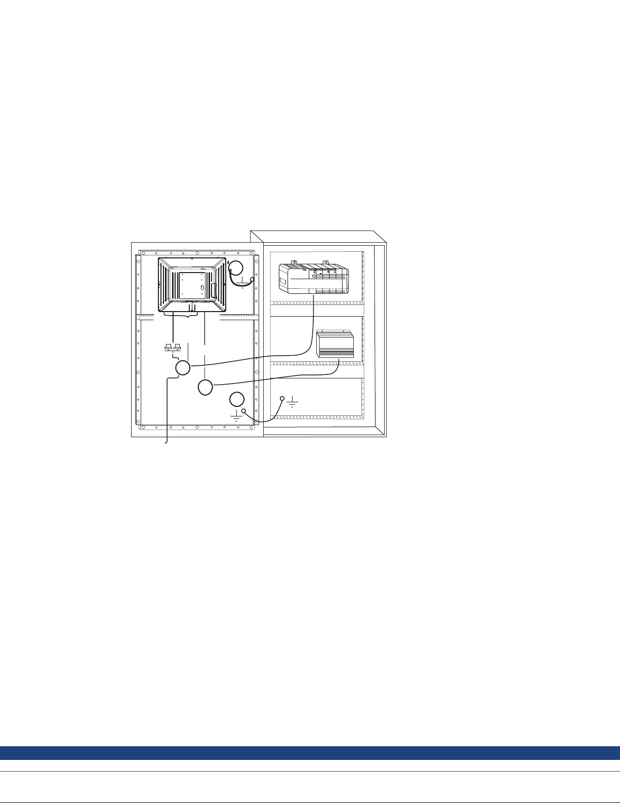
8.1 Grounding the Operator Panel
Door
Operator panel
1
Ferrite core
6
3
2
5
4
Mounting plate in the cabinet
Power supply
24 V DC
5350
The operator panel’s mounting clamps do not provide a secure grounding connection between the
panel and the device cabinet, see 1 in drawing above.
1.
Connect a wire that is sized correctly according to local electrical codes between the operator
panel’squick-connectplinth and the panel’s chassis, see 2 in drawing above.
2.
Connect a wire or grounding braid that is sized correctly according to local electrical codes
between the operator panel’s chassis and the closest grounding point on the door, see 3 in
drawing above.
3.
4.
ect a strong but short grounding braid between the door and the device cabinet, see 4 in
Conn
ing above.
draw
Twist the cables onto the 24 V DC feed, see 5 in drawing above.
2 turns around the ferrite core provide 4 times the suppression of 1 turn.
3 turns around the ferrite core provide 9 times the suppression of 1 turn.
A ferrite core suppresses disturbances to the 24 V feed, see 6 in drawing above.
e:
Not
grounding wires should be short and the conductor should have a large area.
The
ng, thin grounding wire has a very high impedance (resistance) at high frequencies and will not guide
Alo
sturbances to the grou nd.
di
lti-wire conductors are better than single wire conductors with the same area.
Mu
raided conductor wire withthesame area is even better. The best is a short, thick grounding braid.
Ab
ky
Kollmorgen | October 2014
26
Page 27

8.2 Ethernet Connection in the Operator Panel
AKI-CDC-MOD-12T | ADDITION AL INSTALLATION TIPS
Industrial Ethernet
RJ45
RJ45
1
RJ45
RJ45
Operator panel
Shielded
0.1 μF
250 V
In some
capaci
industrial units for Ethernet, the RJ45 contact’s shield is connected to the chassis via a
tor,see 1 in drawing a bove.
RJ45
3
4
1-1
2-2
3-3
8-8
Short and
unshielded
5
Operator panel
RJ45
Operator panel
RJ45
Operator panel
RJ45
2
The operator panel’s Ethernet shield is directly connected to the chassis, see 2 in drawing above.
1.
Check whether the other Ethernet unit has its shield directly grounded or grounded via a capacitor.
Note:
y cases, connecting the shielded Ethernet cabling to the chassis at both endsisinappropriate. Hum or
In man
ding loops can occur. Unshielded cabling may even result in fewer communication errors.
groun
A good solution may be to use a shielded Ethernet cable, but to connect the shield at one end only.
One option is to break the shield, see 3 in drawing above.
A more elegant method is to expand the shielded Ethernet cabling with a piece of unshielded Ethernet
cable, see 4 in drawing above.
The shield can be grounded via an external 0.1 µF/250 V plastic capacitor,see 5 in drawing above.
This will connect the HF transients to ground.
ky
Kollmorgen | October 2014
27
Page 28

8.3 To Achieve Better EMC Protection
AKI-CDC-MOD-12T | ADDITION AL INSTALLATION TIPS
• Use shielded c
ables for RS232 comm u nication.
• Use twisted pair and shielded cabling for RS422 and RS485.
• Use the cablin
g intended for the bus type; Ethernet, Profibus, CC-Link, CAN, Device Net etc.
• Install and connect according to applicable specifications for the relevant bus standard.
• Use shielded c
abling for Ethernet, preferably with foil and a braided shield.
• D-sub covers should be shielded, and the shield should be connected to the cover 360° where
the cable enters.
• Connect the s
Ground plate Ground plate in another building
With longe
should onl
r distances, there is a risk that the ground potential may be different. Inthat case, the shield
y be connected at one end. A good alternative is to connect the other end of the shield to the
ground via
HF, but on
ly connected to the ground at one end in terms of LF, thus avoiding the 50/60 Hz grounding
hield at both ends.
Shielded cable
0.1 μF/250 V
Ground plane 1 Ground plane 2
Not same potential
a 0.1 µF/250 V plastic capacitor. Both ends are then connected to the ground in terms of
loops.
Metal cabinet Metal cabinet
Terminal or connector Terminal or connector
Cable clamp
in steel
Short distance
EMC cable gland
Shielded cable
1.
2.
n EMC cable gland or regular p lastic cable gland, remove the outer jacket and connect the
Use a
ld to the installation plate with a 360° metalcable clamp.
shie
Place the 24 V DC and communications cabling in one cable trunk/cable duct and 230/380 V AC
Shielded cable
Plastic cable gland
in another. If the cables need to be crossed, cross them at 90° only. Avoid combining the cabling
for stronger 24 V DC outputs with the communication cabling.
Ferrite cores that are snapped onto the shielded cabling may remove minor disturbances. Large
ferrite pieces that are snapped onto unshielded cabling and where the wires go 2-4 times around the
cores are approximately 5-25 times more efficient.
ky
Kollmorgen | October 2014
28
Page 29

8.4 Ambient Temperature
AKI-CDC-MOD-12T | ADDITION AL INSTALLATION TIPS
The maximum am
ambient tempe
bient temperature for the operator panel is provided in the specifications. The
rature refers to the temperature in the device cabinet which cools the operator panel’s
electronics.
To p
50 °C inside
Operator
panel
30 °C outside
Middle
45 °C inside
Bottom
40 °C inside
Power
Power
Power
Axial fan
120 x 120 mm
Airflow
In most cases, the ambient temperature for the operator panel is significantly higher than the device
cabinet’sambient temperature.
If the cabinet is tall and there are a number of heat-generating devices, the temperature at the top
of the cabinet will be considerably higher than the theoretical temperature increase that would be
expected. Allelectronicsare sensitive to heat. The lifesp an of a n electrolytic capacitor is cut in half
with an 8-10 °C increase in temperature. A15-20 °C temperature increase results in a quarter of the
lifespan etc.
Rittal has a good program for estimating the anticipated average temperature in the cabinet as well as
a large program for controlling the temperature in the device cabinet.
An enamel-coated steel cabinet has a radiant heat value of 5.5 W/m
2
and degrees C.
Installing a fan inside the cabine t will evenout the temperature,while moving air provid e s
considerably better cooling than still air.
Install the fan so that it sits in the cooler area and blows cold air against the operator panel. Ifthe fan
is mounted at the top and sucks warm air upwards, the fan’s ambient temperature will be higher,
resulting in a shorter lifespan.
The operator panel’s loss effect = supply voltage x current. Virtually no power goes to external users
and no loss effects due to inputs.
ky
Kollmorgen | October 2014
29
Page 30

8.5 Safety
AKI-CDC-MOD-12T | ADDITION AL INSTALLATION TIPS
Most of the ope
Power supply
230 V AC to 24 V DC
1
Power supply
230 V AC to 24 V DC
2
Power supply
230 V AC to 24 V DC
3
230 V AC
rator panels are fed with 24 V DC.
+24 V
0 V
4
+24 V
0 V
4
Distance?
+24 V
0 V
4
Operator panel
Operator panel
Operator panel
Small controller with expansion unit
COM1
COM100
Ch0
Ch1
Ch100
Ch101
5355
If a pow
proble
er supply that meets safety standards is used and only feeds the operator panel, there is no
m. See 1 in drawing above.
However,ifa 24 V unit that also feeds other units is used, there is reason to be cautious, see 2 in
drawing above. The operator panel does not have insulation that meets safety requirements in the
event of a potential short circuit between 230 V AC and 24 V DC. It is assumed that the 24 V feed is
secure, for example, SELV according to EN 60950 (protection against electric shock) and UL 950.
Note:
Hereisanexamplethatexplainswhyasecure24VDCfeedcanberuinedbymixing24Vrelaycontactswith
230 V AC relay contacts in a smaller controller. Check that the clearances and creepage distancesbetween
24 V DC and 230 V AC fulfil l EN 60950 or UL 950. If not, input a separate 24 V unit into the operator panel.
If there is a substantial dist ancebetween the relay contactsfor 24 V DC a nd 230 V AC, it is OK to use
the same 24 V devices for all feeds. See 3 in drawing above.
Connect 0 V on the 24 V feed to the ground, see 4 in drawing above. This offers three advantages:
• Safety is increased. The 24 V feed will not be live in the event of a faulty connection or short circuit
between 0 V (24 V) and 230 V phase.
• Transientson the 24 V feed are connected to the ground.
• No risk that the 24 V feed is at a high level in relationship to the ground. Thisis not unusual since
there is high static electricity.
ky
Kollmorgen | October 2014
30
Page 31

8.6 Galvanic Isolation
AKI-CDC-MOD-12T | ADDITION AL INSTALLATION TIPS
There is no gal
8.7 Cable and Bus T
• If maximum transfer distance and maximum transfer speed is needed, shielded and twisted pair
cable should be used. The m utual capacitance may not exceed 52.5 pF/m, and the cable area
should be at least 0.25 mm
• 0 V,thereference voltage for communication should be included in the cabling. Withtwo-way
communication use two pairs; one pair for communication and one pair for 0 V.
• The shield must be grounded at one end. The other end is usually grounded, but with longer
distances or when there is a differencein the ground potential, the shield should be connected
to the ground via 0.1 µF/250 V plastic capacitor to prevent ground current in the braided shield.
A number of manufacturers recommend that the shield be grounded at each node. Various
manufacturers have different systems for bus termination.
Depending on the recipients’ design, the bus wires may be on the same level or require pull-up or
pull-down to ensure that no faulty signals are detected when the bus is in resting mode (all transmitters
are disconnected).
vanic isolation on any part of the HMI panel.
ermination RS485
2
(AWG 24).
ky
Kollmorgen | October 2014
31
Page 32

8.8 Boot Priority
AKI-CDC-MOD-12T | ADDITION AL INSTALLATION TIPS
The boot prior
Pressing F7 during boot will display a drop down menu with all available bootable devices.
A change of the
to the factory
8.9 Entering BIO
Caution:
Unless you are an expert computer user,donotchange the BIOS settings for this program.
Certainchanges can causeyour operator panel to work incorrectly.
Note:
Before using BIOS setup, it is recommended to write down the setup informationfor future
reference.
Note:
It is reco
any compo
serial d
ity is the order in which the hardware storage devices are read.
boot priority is only temporary. Onnext startup the boot priority will be restored back
setting.
S
mmended to turn on and shut down the operator panel at least once before installing
nents/cardsor before connecting the panel to external devices,like for example
evices.
1.
Connec
2.
Connect power supply and turn on the operator panel.
3.
While booting, press the F2 key immediately after the keyboard is initialized. The initialization is
indicated by the keyboard LED's.
If F2 is pressed before the keyboard is initialized, this keystroke will be lost.
If you waited too long and the operating system logo appears, continue to wait until the operating
system desktop is appearing. Then,shut down the operator panel and try again.
Note:
The keys used to enter the B IOSsetup are DEL and F2.
The system setup allows to:
•Cha
•Set
•Set
•Rea
For more information, refer to the BIOS manual.
8.10 ResetSwitch
t a USB Keyboard.
nge the system configuration (new installed hardware).
up boot devices and sequences.
up or change user options, for example passwords.
d the installed memory and environmental parameters, for example CPU heat.
A reset switch is located under the fanlid.
ky
Kollmorgen | October 2014
32
Page 33

AKI-CDC-MOD-12T | ADDITION AL INSTALLATION TIPS
Follow the instructions in chapter Replacing the Fan and Filter on how to remove the fan lid to access
the reset switch.
ky
Kollmorgen | October 2014
33
Page 34

Kollmorgen | October 2014 34
9 APPENDIX
This appendix provides information for accessing the HMI service menu and interfacing
an AKI to an AKD PDMM and Programmable Automation Controller (Panel PAC).
9.1 HMI Service Menu
The HMI provides a service setting menu to perform touch calibration, IP settings, selftests, and other options. After a project is loaded onto a panel, the service menu is
accessible by following the procedures described below.
1. Apply power to the panel.
2. When the hourglass displays, press a finger on the screen and hold for approximately
20 seconds.
3. Enter a PIN code if the service menu is password protected.
4. The touch calibration screen displays the following message:
“Tap anywhere on screen or touch calibrate will start in 10 seconds.”
5. Press finger on screen again to enter the service menu.
The Service Menu displays:
AKI-CDC-MOD-12T | APPENDIX
Note: Additional information about the Service Menu options are available in the
Kollmorgen Visualization Builder (KVB) online help: HMI Panel System Software/Service
Menu
9.2 HMI to PDMM Connection and Programming
Modbus TCP is used to communicate from the Ethernet port of an AKI panel to the X32
connector on the top of an AKD PDMM, also referred to as an Ethernet service port. If the
AKD PDMM is connected to a network, switch, or hub you can have Modbus
communication active at the same time as you are programming the AKD PDMM with
your computer through KAS Integrated Development Environment software (KAS IDE).
This is also appropriate for TCP, HTTP, Profinet, or Ethernet IP communication that also
uses the X32 port and any combination can be active simultaneously.
Page 35

Kollmorgen | October 2014 35
When using HMI panels the Modbus addresses are setup automatically through linking of
the KAS IDE development software with the KVB development software. This is
controlled in the KAS IDE dictionary using the KVB column and checkboxes that can be
selected to share that variable (global or local) over Modbus. Each time the project is
compiled this list is updated. If both software packages are installed on your computer,
use the KAS IDE by right-clicking on the System option in the Project Explorer and select
“Add HMI Device” to display a list of HMI panels that Kollmorgen has available. Doubleclick on the project to launch KVB and automatically import tags and the target IP
address for the KAS controller.
9.3 HMI to PAC Connection
The same Ethernet service port of the AKI panel can be used to connect and interface
with a PAC. Using a standard Ethernet cable, connect the HMI to your network, switch, or
hub. Communication is achieved by using Ethernet TCP/IP and the target IP address for
the PAC is automatically linked in the KVB software as described in the HMI to PDMM
Connection and Programming section of this document.
AKI-CDC-MOD-12T | APPENDIX
Page 36

About K
Kollmorgen is a leading provider of motion systems and components for machine builders. Throughworldclass
knowledge in motion, industry-leading quality and deep expertise in linking and integrating standard and custom
products, Kollmorge n delivers breakthrough solution s that a re unmatched in performance,reliability and e as e-o f-use,
giving machine builders an irrefutable marketplace advantage.
For assistance with your application needs, visit www.kollmorgen.comor contact us at:
OLLMORGEN
North America
KOLLMORGEN
203A West Rock Road
Radford, VA24141USA
www.kollmorgen.com
Web:
support@kollmorgen.com
Mail:
Tel .: +1 - 540 - 633 - 3545 Tel.: +49 - 2102 - 9394 - 0 Tel.: +86 - 400 666 1802
Fax: +1 - 540 - 639 - 4162 Fax: +49 - 2102 - 9394 - 3155 Fax: +86- 10 6515 0263
.
Europe
KOLLMORGEN Europe GmbH
Pempelfurtstraße 1
40880 Ratingen, Germany 22 Jianguomen Wai Street
www.kollmorgen.com
Web:
technik@kollmorgen.com
Mail:
Asia
KOLLMORGEN
Rm 2205, Scitech Tower,China
www.kollmorgen.com
Web:
sales.asia@kollmorgen.com
Mail:
 Loading...