

Page 1
GraphicOperatorTerminal
Installation
Manual
ionA,April2017
Edit
AKI2G-CDB-MOD-12T-00012.1”TouchscreenHMI
Keepallmanualsasaproductcomponentduringthelifespanoftheproduct.
Passallmanualstofutureusers/ownersoftheproduct.
Page 2

RecordofDocumentRevisions
Revision Remarks
A,04/2017
Preliminaryedition
IMPORTANTNOTICE
Technicalchangeswhichimprovetheperformanceofthedevicemaybe made withoutpriornotice!
PrintedintheUn ited StatesofAmerica. Thisdocument istheintellectualpropertyofKollmorgen™. Allrightsreserved. No
partofthi
copiedordistributed byelectronicmea ns withoutthewr ittenpermissionofKollmorgen™.
sworkmaybe reproducedina ny form(byphotocopying,microfilmoranyothermethod)orstored,processed,
ky
Kollmorgen|April2017
2
Page 3

AKI2G-CDB-MOD-12T-000|CONTENTS
1 General
1.1 AboutThisM
2 SafetyPrecau
anual .......................................................................
tions
2.1 General ................................................................................... 5
2.2 DisposalR
2.3 ULandcULI
2.4 DuringIns
2.5 DuringUse
2.6 Servicea
2.7 Dismantl
2.8 Appearan
3Installati
3.1 SpaceRe
3.1.1 AKI2G
3.2 Install
3.2.1 Conne
3.2.2 Othe
4 Technica
5Chemical
5.1 MetalC
5.2 TouchS
5.2.1 Aut
5.2.2 Tou
5.2.3 Tou
6Operato
6.1 Conn
6.2 Comm
6.3 Digi
talOutputs ............................................................................
6.4 AKI2
7Additi
onalInstallationTips
7.1 Gro
7.2 Eth
undingtheHMI panel ................................................................
ernet Connectionin theOperatorPanel ............................................
7.3 ToA
7.4 Amb
7.5 Saf
7.6 Ga
7.7 Ca
ety .....................................................................................
lvanicIsolation ........................................................................
bleandBusTermination RS485 .....................................................
equirementsUnderWEEE Regulations ...................................
nstallation ..................................................................
tallation ........................................................................
................................................................................
nd Maintenance ...............................................................
ingandScrapping ..............................................................
ce of Airin TouchScreen .....................................................
on
quirements ....................................................................
-CDB-MOD-12T-000 ....................................................
ation Process ......................................................................
ctionsto theController ...................................................
rConnectionsand Peripherals ............................................
lData
Resistance
asing .............................................................................
creen andOverlayMaterial .....................................................
oflex EBA 180L ...............................................................
ch ScreenSurface(for12”Panels) .........................................
ch ScreenProtector .........................................................
rPanelDrawings
ectors ...............................................................................
unicationPorts ....................................................................
G-CDB-MOD-12T-000Outline ....................................................
chieveBetterEMC Protection ......................................................
ientTemperature ....................................................................
4
5
5
7
7
7
8
8
9
9
10
11
11
14
15
15
15
16
17
18
19
20
21
22
23
24
25
26
27
ky
Kollmorgen|April2017
3
Page 4

1 GENERAL
1.1 AboutThisManual
AllAdvancedKollmorgenInterfacesaredevelopedtosatisfythedemandsofhuman-machine
communication. Built-infu nctionssuchasdisplayingandcontrollingtext,dynamicindication,time
channels,alarmandrecipehandlingareincluded.
TheAdvancedKollmorgenInterfacesworks primarilyinanobject-orientedway,makingiteasyto
understandanduse. ConfigurationiscarriedoutonaPCusingth e KollmorgenVisualizationBuilder
configurationtool. Theprojectcanthenbe transferredandstoredintheoperatorpanelitself.
VarioustypesofautomationequipmentsuchasPLCs,servosordrivescanbeconnectedtothe
AdvancedKollmorgenInterfaces. Inthismanual,theterm“thecontroller”referstotheconnected
equipment.
Thismanualexplainshowtoinstalltheoperatorpanel. PleaserefertotheKollmorgenVisualizationBuilderProgrammingandInstallationmanualforfurtherinformation.
AKI2G-CDB-MOD-12T-000|GENERAL
ky
Kollmorgen|April2017
4
Page 5

2 SAFETYPRECAUTIONS
Boththeinstallerandtheownerand/oroperatoroftheoperatorpanelmustreadandunderstand
thisinstallationmanual.
2.1 General
• Readthesafetyprecautionscarefully.
• Checkthedeliveryfortransportationdamage. Ifdamageisfound,notifythesupplierassoonas
possible.
• DonotusetheHMIpanelinanenvironmentwithhighexplosivehazards.
• Thesupplierisnotresponsibleformodified,alteredorreconstructedequipment.
• Useonlypartsandaccessoriesmanufacturedaccordingtospecificationsofthesupplier.
• Readtheinstallationandoperatinginstructionscarefullybeforeinstalling,usingorrepairing
theHMIpanel.
• Neverallow fluids,metalfilingsorwiringdebristoenteranyopeningsintheHMIpanel. Thismay
causefireorelectricalshock.
•OnlyqualifiedpersonnelmayoperatetheHMIpanel.
• StoringtheHMIpanelwherethetemperatureislower/higherthanrecommendedinthismanual
cancausetheLCDdisplayliquidtocongeal/becomeisotropic.
• TheLCDdisplayliquidcontainsapowerfulirritant. Incaseofskincontact,washimmediately
withplentyofwater. Incaseofeyecontact,holdtheeyeopen,flushwithplentyofwater andget
medicalattention.
•Thefiguresinthismanua l serveanillustrativepurpose. Becauseofthema ny variables
associatedwithanyparticula r installation,thesuppliercannota ssumeresponsibilityforactual
usebased ont he figures.
• ThesupplierneitherguaranteesthattheHMIpanelissuitableforyourparticularapplication,nor
assumesresponsibilityforyourproductde s ign,installationoroperation.
• Itisrecommendedtoturnonandshutdown theHMI panelatleastoncebeforeinstallinga ny
components/cardsorbeforeconnectingtheoperatorpaneltoexternaldevices;forexample
serialdevices.
• ForMarinepanelsonly:
– TheHMIpanelmustbeinstalledandoperatedasdescribedinthisdocumenttomeetthis
certification.
– Observeprecautionsforhandlingelectrostaticdischargesensitivedevices
AKI2G-CDB-MOD-12T- 000|SAFETYPRECAUTIONS
2.2 DisposalRequirementsUnderWEEERegulations
rofessionalusersinthe EuropeanUnion: Ifyouwishtodiscardelectricalandelectronic
Forp
pment(EEE),pleasecontactyourdealerorsupplierforfurtherinformation.
equi
FordisposalincountriesoutsideoftheEuropeanUnion: Ifyouwishtodiscardthisproduct
pleasecontactyourlocalauthoritiesordealerandaskforthecorrectmethodofdisposal.
2.3 ULandcULInstallation
Caution:
Thissectionisonly validforUL labeledpanels.
ky
Kollmorgen|April2017
5
Page 6

AKI2G-CDB-MOD-12T- 000|SAFETYPRECAUTIONS
• ThisequipmentissuitableforuseinClass2non-hazardouslocationsonly. [Combinationsof
equipmentinyoursystemaresubjecttoinvestigationbythelocalauthorityhavingjurisdiction
atthetimeofinstallation].
• AlldeviceshavetobesuppliedbyaClass2powersupply.
OnlyULand cULapprovedexpansionunitsareallowedto beconnectedto theportdesignated
“EXPANSION”. Atthemomentthere arenosuchunitsevaluatedor allowed.
SEULESLESUNITÉSD'EXTENSION CERTIFIÉESUL ET
cULPEUVENTÊTRERACCORDÉES AUPORTDÉSIGNÉ«EXPANSION».
ÀL'HEUREA CTUELLE, AUCUNEU NITÉ DECE TYPEN'A ÉTÉTESTÉE
OUAUTORISÉE.
•Thisequip
equipment
atthetime
• Alldevice
mentissuitableforuseinClass2non-hazardouslocationsonly. [Combinationsof
inyoursystemaresubjecttoinvestigationbythelocalauthorityhavingjurisdiction
ofinstallation].
shavetobesuppliedbyaClass2powersupply.
OnlyULand cULapprovedexpansionunitsareallowedto beconnectedto theportdesignated
“EXPANSION”. Atthemomentthere arenosuchunitsevaluatedor allowed.
SEULESLESUNITÉSD'EXTENSION CERTIFIÉESUL ET
cULPEUVENTÊTRERACCORDÉES AUPORTDÉSIGNÉ«EXPANSION».
ÀL'HEUREA CTUELLE, AUCUNEU NITÉ DECE TYPEN'A ÉTÉTESTÉE
OUAUTORISÉE.
• Thisproductcontainsabattery;thismustonlybechangedinanareaknowntobenon-hazardous.
• ReplacethebatterywithaBR2032battery. Useofanothertypeofbatterymaypresentariskof
fireorexplosion.
rymayexplodeifmistreated. Donotrecharge,disassembleor disposeofin fire.
Batte
roductcontainsaBR2330A batterythatisnotuserreplaceable.
Thisp
LABAT
NELA
PASD
CEPR
REMP
TERIEPEUTEXPLOSERENCASDEMAUVAISEMANIPULATION.
RECHARGEZPAS,NELADÉMONTEZ PASETNELAJETEZ
ANSLEFEU.
ODUITCONTIENTUNE PILEBR2330A QUINE PEUTPASÊTRE
LACÉEPARL'UTILISATEUR.
• Foruseonaflatsurfaceofatype4Xenclosureindooruseonly.
• Useminimum75°Ccopperconductorsonly.
• Tomakewiringconnectionstothepowersupplyconnector,followthetablewithcableandtorque
specificationsbelow:
ky
Kollmorgen|April2017
6
Page 7

AKI2G-CDB-MOD-12T- 000|SAFETYPRECAUTIONS
TerminalBlockConnector WireSizeAWG TQLb.In.
X1/X100Phoen
X1/X100Anytekconnectors AWG24–12
X1/X100DECA
• ThesedevicesareClass2suppliedprogrammablecontrollers(industrialPCs)fortheusein
industrialcontrolequipmentandareintendedtobe(front)panelmounted(Type12and4xfor
indooruseonly).
Caution:
Theenclosureprovidesa degreeofprotectionofatleastIP20, butwheninstalledinan
apparatus,itshouldmeetIP65..
LEBOÎTIEROFFR E UNDEGRÉ DEPROTECTION D'AUMOINS IP20,MAIS
LORSQU'ILESTIN STALLÉDANSUN APPAREIL,ILDOITÊTRE DECLASSE IP65..
2.4 DuringInstallation
• TheHMIpanelisdesignedforstationaryinstallationonaplanarsurface,wherethefollowing
conditionsarefulfilled:
– nohighexplosiverisks
– nostrongmagneticfields
– nodirectsunlight
– nolarge,suddentemperaturechanges
ixconnectors
connectors
AWG30–12
AWG24–12
5–7
3.5
7
• InstalltheHMIpanelaccordingtotheaccompanyinginstallationinstructions.
• GroundtheHMIpanelaccordingtothe accompanyinginstallationinstructions.
•OnlyqualifiedpersonnelmayinstalltheHMIpanel.
• Separatethehighvoltage,signal,andsupplyc ables.
• MakesurethatthevoltageandpolarityofthepowersourceiscorrectbeforeconnectingtheHMI
• Peripheralequipmentmustbeappropriatefortheapplicationandlocation.
2.5 DuringUse
• Keep
•Emer
•Don
2.6 Ser
viceandMaintenance
•Onlyqualifiedpersonnelshouldcarryoutrepairs.
• Theagreedwarrantyapplies.
• Beforecarryingoutanycleaningormaintenanceoperations,disconnecttheequipmentfrom
• Cleanthedisplayandsurroundingfrontcoverwitha softclothandmilddetergent.
paneltothepoweroutlet.
theHMIpanelclean.
gencystopandothersafetyfunctionsmaynotbecontrolledfromthe HMIpanel.
otuseexcessiveforceorsharpobjectswhenoperatingthe touchscreen.
theelectricalsupply.
ky
Kollmorgen|April2017
7
Page 8

• Replacingthebatteryincorrectlymayresultinexplosion. Onlyusebatteriesrecommended
bythesupplier. Duringthewarrantyperiod,thebatteryneedstobereplacedbyanauthorized
Kollmorgenservicecenter.
2.7 DismantlingandScrapping
AKI2G-CDB-MOD-12T- 000|SAFETYPRECAUTIONS
• TheHMIpanel
• Thefollowin
environment
2.8 Appearance
Thelayerstructureofthetouchscreencontainsair. Inrarecases,theappearanceofbubblescan
arise. ThisispurelycosmeticanddoesnotaffectthefunctionalityoftheHMIpanel. Theappearance
canoccurundercertainenvironmentalconditionssuchastemperature,humidity,andatmospheric
pressure.
orpartsthereofshallberecycledaccordingtolocalregulations.
gcomponentscontainsubstancesthatmightbehazardoustohealthandthe
: lithiumbattery, electrolyticcapacitor,anddisplay.
ofAirinTouchScreen
ky
Kollmorgen|April2017
8
Page 9

3INSTALLATION
3.1 SpaceRequirements
• Maximuminstallationplatethickness12”: 8mm
• Thefollowingdrawingsshowthespacerequirementsinmillimeterswheninstalling theoperator
panel. Thedrawings areonlyillustrativeandmay beoutofproportion.
AKI2G-CDB-MOD-12T-000|INSTALLATION
3.1.1 AKI2G-CDB-
242 mm
MOD-12T-000
50 mm
100 mm
100 mm
340 mm
50 mm
100 mm
49 mm
ky
Kollmorgen|April2017
9
Page 10
3.2 InstallationProcess
AKI2G-CDB-MOD-12T-000|INSTALLATION
Thefollowing
isneeded:
• APhillips/slotscrewdriver
1.
Unpackandche
Note:
PlacetheHMIpanel onastablesurfaceduringinstallation.
DroppingtheHMI panelorletting itfallmaycausedamage.
2.
TocutacorrectopeningfortheHMIpanel,usethecutoutdimensionsintheoutlinedrawing. For
ckthedelivery. Ifdamageisfound,notifythesupplier.
moreinformation,seesectionsOperatorPanelDrawingsandTechnicalData.
3. InstalltheHMIpanelintothecutout.
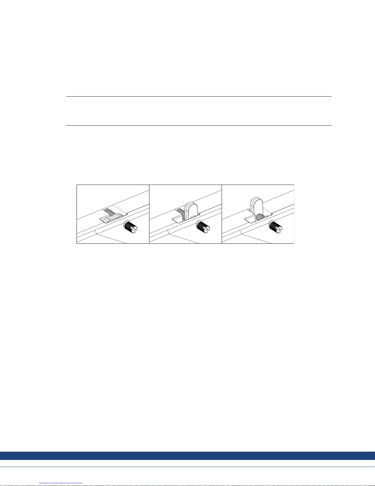
4.
SecuretheHMIpanelinpositionby screwingtheslottedthumbscrewclockwise,allowingthe
built-inbrackettoflipoutandtightenagainstthecabinet.
Figure 3-1: Tightenthescrewsto0.7Nm± 0.2Nm.
5.
Incaseswherethefrontpanelseal(IP54orgreater,NEMA-4X)iscritical,useatorquewrenchto
ensureallscrewsaretorquedwithinthespecificationabove.
ky
Kollmorgen|April2017
10
Page 11

AKI2G-CDB-MOD-12T-000|INSTALLATION
6.
Connectthecab
lesinthespecifiedorder,accordingtothedrawingandstepsbelow.
Caution:
TheHMIpanelmust bebroughtto ambienttemperaturebefore itisstartedup. Ifcondensation forms,ensure
•
thattheHMIpanel isdrybeforeconnecting ittothep oweroutlet.
• EnsurethattheHMIpanel andthecontrollersystemhave thesameelectricalgrounding(reference voltage
level),otherwiseerrorsincommunicationmay occur.
• Ensurethatthe voltageandpolarityofthepowersourceiscorrect.
• Separatehighvoltage cablesfromsig nalandsupplycables.
• Shieldedcommunicationcables arerecommended.
B
RS232/
RS422/
RS485
24V DC
C
Power
Controller
24V DC
D
A
Ethernet
Figure 3-2: Theimageisillustrativeonly andmaydifferslightly fromtheactual panel.
– ConnectcableA.
– ConnectcableB,usinganM5screwandagroundingconductor(asshortaspossible),thatis
sizedcorrectlyaccordingtolocalelectricalcodes.
– ConnectcableC.
– ConnectcableD. Therecommendedcross-sectionofthecableis1.5mm.
7.
Carefullyremove theprotec tive filmovertheHMIpaneldisplay,takecaretoavoidstaticelectricity
thatcoulddamagethepanel.
3.2.1 ConnectionstotheController
informationaboutthecablestobeusedwhenconnectingtheHMIpaneltothecontroller,please
For
ertothehelpfileforthedriverinquestion.
ref
3.2.2 OtherConnectionsandPeripherals
Cables,peripheralequipmentandaccessoriesmustbesuitablefortheapplicationandits
environment. Forfurtherdetailsorrecommendations,pleaserefertothesupplier.
ky
Kollmorgen|April2017
11
Page 12

4 TECHNICALDATA
Parameter AKI2G-CDB-MOD-12T-000
Frontpanel,WxHxD 340x242x8mm
AKI2G-CDB-MOD-12T-000|TECHNICALDATA
Cutoutdimensions,W×H
Mountingdepth
Standalonemounting VESA75x75Note: Maximumscrewlengthfor
Frontpanelseal IP65
Rearpane
Touchs creenmaterial
Frameov
Touchs creenoperations
Reversesidematerial Powder-coatedaluminum
Framematerial Powder-coatedaluminum
Weigh
CPU
SerialportforCOM1RS232,COM2
RS422/RS485andCOM3RS485
lseal
erlay
t
324x226mm
49mm(149mm
VESAmountingis4mm. Usageoflongerscrews
mayleadtodamage.
IP20
Polyesteronglass,ITOfilm,resistive
AutoflexEBA180L
nfingertouchoperations
1millio
2.6kg
i.MX6DualLite
DualCortex-A9
1.0GHz
512kBL2 cache
9-pinD-subcontactwithRS232RTS/CTS,
chassis-mountedfemalewithstandardlocking
screws4-40UNC
includingclearance)
EthernetLANA
EthernetLANB
USB 2×USB Host2.0,maxoutputcurrent500mA
DIO(outputs,potentialfree) N/A
Externalstoragemedia
Flashmemory(applicationmemory) 1.5GBSSD(eMMC)
MemoryRAM
NVRAM
LED 1×Multicolor
Realtimeclock Yes
Battery LithiumbatterytypeBR2032,exchangeable
Powerconsumptionatratedvoltage 28.8W
Fuse
ky
10/100Mbit/s(shieldedRJ45)
10/100Mbit/s(shieldedRJ45)
1×SDcard
1GB(DDR3)
N/A
InternalDCfuse,4 AT,5×20mm
Kollmorgen|April2017
12
Page 13

AKI2G-CDB-MOD-12T-000|TECHNICALDATA
Parameter AKI2G-CDB-MOD-12T-000
Powersupply
+24VDC(18to3
CE:Thepowersupplymustconformwiththe
requirementsaccordingtoIEC60950and
IEC61558-2-4.
ULandcUL:Th
entsforclassIIpowersupplies.
Display
therequirem
TFT-LCDwithLEDbacklight
1280×800pixels,262kcolors
Activeareaofdisplay,W×H
Pixelerrors
Backlightbrightness
Backlightlifetime
261.1x163.2mm
ClassI(ISO9241-307)
400cd/m
2
50,000hours
Operatingtemperature -10°Cto+60°C
Storagetemperature -20°Cto+70°C
Relativehumidityinoperation
Vibration
Mechanicalshock
5%–85%non-condensation
1g,accordingtoIEC60068-2-6,TestFc
15g,half-sine,11msaccordingtoIEC60068-2-27
Approvalsandcertifications CE/FCC/KC
Informationisavailableonwww.kollmorgen.com
2VDC)
epowersupplymust conformwith
ULapproval
,informationavailableatUL.com
Yes
Marinecert ificates Informationisavailableonwww.kollmorgen.com
ky
Kollmorgen|April2017
13
Page 14

5 CHEMICALRESISTANCE
5.1 MetalCasing
Theframeandcasingmaterialispowder-coatedaluminum. Thispowderpaintwithstandsexposure
tothefollowingchemicalswithoutvisiblechange:
Aceticacid10% Phosphoricacid4%
Citricacid10% Phosphoricacid10%
AKI2G-CDB-MOD-12T-000|CHEMIC AL RESISTANCE
Diesel
Distilledwater
Edibleoi
Fueloil
Hydrogenperoxide3%
Thepowderpaintshowslimitedresistancetothefollowingchemicalsatroomtemperature:
Butanol
Hydrochloricacid5% Nitricacid10%
Isopropylalcohol
Sodiumhypochlorite10%
Note:
Ifexposuretoany oftheabovechemicalsisdemanded,itisrecommendedtofirsttest the
chemicalinahidden spotofthemetalcasing.
Thepowderpaintshowslittleornoresistancetothefollowingchemicalsatroomtemperature:
l
Seawater
Sodiumchloride2%
Sodiumchloride20%
Sulphur
Tapwater
Nitricacid3%
Phosphoricacid43%
Turpentine
icacid20%
Aceticacid,conc. Methyl-ethylketone Toluene
Acetone
Ammonia5%
Ammonia,conc.
Ethylacetate
ky
Nitricacid30%
Phenol Xylene
Sodiumhydroxide5%
Sodiumhydroxide30%
Trichlorethylene
97octaneunleadedpetrol
98octaneleadedpetrol
Kollmorgen|April2017
14
Page 15

5.2 TouchScreenandOverlay Material
AKI2G-CDB-MOD-12T-000|CHEMIC AL RESISTANCE
5.2.1 AutoflexEBA18
AutoflexEBA180Lcoverstheoverlaysurroundingthescreen.
SolventResistance
AutoflexEBA1
thefollowin
Acetonitrile Diesel Petroleumspirit
Ajax/Viminsolution Downy/Lenor
Alkalicarbonatesolution
Ammonia(<40%)
Aceticacid(<50%) Glycol
Arielpowderinsolution
Bleach
Castoroil
Caust
Cuttingoil Nitricacid(<10%) WhiteSpirit
Cyclohexanol Paraffinoil
Diacetonealcohol Persilpowderinsolution
(1)
(1)
icsoda(<40%)
Extremelyfaintglossingof thetexturewas noted.
0L
80Lwithstandsexposureofmorethan24hoursdurationunderDIN42115Part2to
gchemicalswithoutvisiblechange:
(1)
(1)
(1)
(1)
(1)
(1)
Ethanol
Glycerine Potassiumhyd roxide(<30%)
(1)
Gumptio
n
Hydrochloricacid(<36%) Sulfuricacid(<10%)
doil
Linsee
Methanol
(1)
Phosphoricacid(<30%)
Potassium
PureTurp
SBP60/9
Tomato
Trich
Wind
ferricyanide
entine
(1)
5
ketchup
loroaceticacid(<50%)
(1)
ex
AutoflexEBA180LwithstandsDIN42115Part2exposureofupto1hourdurationtoglacialacetic
acidwithoutvisiblechan ge.
oflexEBA180Lisnotresistanttohighpressuresteamatover100°Corthefollowingchemicals:
Aut
centratedmineralacids
Con
Concentratedcausticsolution
5.2.2 TouchScreenSurface(for 12”Panels)
hetouchscreensurfaceontheoperatorpanelwithstandsexposuretothefollowingsolventswithout
T
isiblechange:
v
Thescreensurfaceontheoperatorpanelwithstandsexposuretothefollowingsolventswithout
visiblechange:
Solvents
Acetone 10minutes
Isopropanol 10minutes
Toluene 5hours
Benzylalcohol
Methylenechloride
Time
ky
Kollmorgen|April2017
15
Page 16

5.2.3 TouchScreenProtector
AKI2G-CDB-MOD-12T-000|CHEMIC AL RESISTANCE
Forharshenvi
filmtoguardth
ronmentsandexposuretooutdoorconditions,itisrecommendedtouseaprotective
etouchscreenfromdamage. Thisoptionalpartcan beorderedfromKollmorgen.
ky
Kollmorgen|April2017
16
Page 17

AKI2G-CDB-MOD-12T-000|OPERATORPANELDRAWINGS
6 OPERATORPANELDRAWINGS
6.1 Connectors
Figure 6-1: AKI2G-CDB-MOD-12T-000
Pos. Connector Description
1 Powersupply
2
3LANA
4LANB
5
USB USBHost2.0,maxoutputcurrent500mA
COM Serialc
+24VDC (18-32V DC)
10/100Base-T(shieldedRJ45)
10/100Base-T(shieldedRJ45)
ommunicationport
ky
Kollmorgen|April2017
17
Page 18

6.2 CommunicationPorts
AKI2G-CDB-MOD-12T-000|OPERATORPANELDRAWINGS
Pin
Serialport,9-pin female
COM1 COM2 COM3
1
-
2RS232RxD
3
4
5
6
7
8
9
Note:
Inordertoutilizetwocommunicationports,theY-splitcableCAB109mustbeused.
Inordertoutilizethreecommunicationportsthe splitcableCAB150 mustbeused.
To use232+422,use CAB109.
To use232+485,use CAB150.
RS232TxD
-
GND GND
-
RS232RT
S
RS232CTS
-
RS422Tx+
RS485Tx+/Rx+
--
--
RS422Rx+ RS485Tx+/Rx+
RS422Tx-
RS485Tx-/Rx-
--
--
RS422Rx- RS485Tx-/Rx-
-
-
-
ky
Kollmorgen|April2017
18
Page 19

6.3 DigitalOutputs
Ratings
AKI2G-CDB-MOD-12T-000|OPERATORPANELDRAWINGS
Maximumsupplyvoltage
Maximumloadcurrent
32.0V(DC)/22Vrms(AC)
0.5A(DC)/0
.5Arms(AC)
Isolation
Channelto
Channel
1000V(DC)
/550Vrms(AC)
ChanneltoSystem 1000V(DC)/550Vrms(AC)
ky
Kollmorgen|April2017
19
Page 20

6.4 AKI2G-CDB-MOD-12T-000Outline
AKI2G-CDB-MOD-12T-000|OPERATORPANELDRAWINGS
Figure 6-2: AKI2G-CDB-MOD-12T-000
ky
Kollmorgen|April2017
20
Page 21

AKI2G-CDB-MOD-12T-000|A DDITION AL INSTALLATIONTIPS
7 ADDITIONALINSTALLATIONTIPS
Whenexperiencingcommunicationproblemsinnoisyenvironmentsorwhenoperatingcloseto
temperaturelimits,thefollowingrecommendationsaretobenoticed.
7.1 GroundingtheHMIpanel
Door
Operator panel
1
Ferrite core
6
3
2
5
4
Mounting plate in the cabinet
Power supply
24 V DC
5350
ThemountingclampsoftheHMIpaneldonotprovideasecuregroundingconnectionbetweenthe
panelandthedevicecabinet,see1indrawingabove.
1.
Connectawire,thatissizedcorrectlyaccordingtolocale lectricalcodes,betweenthe
quick-connectterminalconnectorontheoperatorpanelandthechassisofthepanel,see 2in
drawingabove.
2.
Connectawireorgroundingbraid,thatissizedcorrectlyaccordingtolocalelectricalc odes,
betweenthechassisoftheHMIpaneland theclosestgroundingpointonthedoor,see3in
drawingabove.
3.
4.
ectastrongbutshortgroundingbraidbetweenthedoorandthedevicecabinet,see4in
Conn
ingabove.
draw
Twistthecablesontothe24VDCfeed,see5indrawingabove.
2turnsaroundtheferritecoreprovide4timesthesuppressionof1turn.
3turnsaroundtheferritecoreprovide9timesthesuppressionof1turn.
Aferritecoresuppressesdisturbancestothe24Vfeed,see6indrawingabove.
e:
Not
groundingwiresshould beshortand theconductorshould havealarge area.
The
ong,thingrounding wirehasaveryhighimpedance(resistance)athighfrequenciesanddoesnotgui de
Al
sturbancestotheground.
di
lti-wireconductorsarebetter thansinglewire conductorswiththe samearea.
Mu
raidedconductorwirewiththesameareaisevenbetter. Thebestisashort, thickgroundingbraid.
Ab
ky
Kollmorgen|April2017
21
Page 22

7.2 EthernetConnectioninthe OperatorPanel
AKI2G-CDB-MOD-12T-000|A DDITION AL INSTALLATIONTIPS
Industrial Ethernet
RJ45
RJ45
1
RJ45
RJ45
Operator panel
Shielded
0.1 μF
250 V
Insome
capaci
industrialunitsforEthernet,theRJ45contact’sshieldisconnectedtothechassisviaa
tor,see1indrawingabove.
RJ45
3
4
1-1
2-2
3-3
8-8
Short and
unshielded
5
Operator panel
RJ45
Operator panel
RJ45
Operator panel
RJ45
2
Theoperatorpanel’sEthernetshieldis directlyconnectedtothechassis,see2indrawingabove.
1.
CheckwhethertheotherEthernetunithasitsshielddirectlygroundedorgroundedviaacapacitor.
Note:
ycases,connecting theshieldedEthernet cablingtothe chassisatbothendsisinappropriate. Humor
Inman
dingloopscanoccur. Unshieldedcabling mayevenresult infewercommunication errors.
groun
Agoodsolutionmaybetouse ashieldedEthernetcable,buttoconnecttheshieldatoneendonly.
Oneoptionistobreakthe shield,see3indrawingabove.
AmoreelegantmethodistoexpandtheshieldedEthernetcablingwithapieceofunshieldedEthernet
cable,see4indrawingabove.
Theshieldcanbe groundedviaanexternal0.1µF/250Vplasticcapacitor,see5indrawingabove.
ThisconnectstheHFtransientstoground.
ky
Kollmorgen|April2017
22
Page 23

7.3 ToAchieveBetterEMCProtection
AKI2G-CDB-MOD-12T-000|A DDITION AL INSTALLATIONTIPS
• Initially,us
etheoriginalcabling fromKollmorgenprimarily.
• UseshieldedcablesforRS232communication.
• Usetwisted pa
irandshieldedcablingforRS422andRS485.
• Usethecablingintendedforthebustype;Ethernet,Profibus,CC -Link, CAN,Device Netetc.
• Installandco
nnectaccordingtoapplicablespecificationsfortherelevantbusstandard.
• UseshieldedcablingforEthernet,preferablywithfoiland abraidedshield.
• D-subcoverss
thecableent
houldbeshielded,andtheshieldshouldbeconnectedtothecover360°where
ers.
• Connecttheshieldatbothends.
Shielded cable
0.1 μF/250 V
Ground plane 1 Ground plane 2
Ground plate Ground plate in another building
Not same potential
Withlongerdistances,thereisariskthatthegroundpotentialmaybedifferent. Inthatcase,theshield
shouldonlybeconnectedatoneend. Agoodalternativeistoconnecttheotherendoftheshieldtothe
groundviaa0.1µF/250Vplasticcapacitor. Bothendsarethenconnectedtothegroundintermsof
HF,butonlyconnectedtothegroundatoneendintermsofLF,thusavoidingthe50/60Hzgrounding
loops.
Metal cabinet Metal cabinet
Terminal or connector Terminal or connector
Cable clamp
in steel
Short distance
EMC cable gland
Shielded cable
1.
UseanEMC cableglandorregularplasticcablegland,removetheouterjacketandconnectthe
Shielded cable
Plastic cable gland
shieldtotheinstallation platewitha360°metal cableclamp.
2.
Placethe24V DCandcommunicationscablinginonecabletrunk/cableductand230/380VAC
inanother. Ifthecablesneedtobecrossed,crossthemat90°only. Avoidcombiningthecabling
forstronger24VDCoutputswiththecommunicationcabling.
Ferritecoresthataresnappedontotheshieldedcablingmayremoveminordisturbances. Large
ferritepiecesthataresnappedontounshieldedcablingandwherethewiresgo2-4timesaroundthe
coresareapproximately5-25timesmoreefficient.
ky
Kollmorgen|April2017
23
Page 24

7.4 AmbientTemperature
AKI2G-CDB-MOD-12T-000|A DDITION AL INSTALLATIONTIPS
Themaximumam
ambienttempe
bienttemperaturefortheoperatorpanelisprovidedinthespecifications. The
raturereferstothetemperatureinthedevicecabinetwhichcoolstheoperatorpanel’s
electronics.
To p
50 °C inside
Operator
panel
30 °C outside
Middle
45 °C inside
Bottom
40 °C inside
Powe r
Powe r
Powe r
Axial fan
120 x 120 mm
Airflow
Inmostcases,theambienttemperaturefortheoperatorpanelissignificantlyhigherthanthedevice
cabinet’sambienttemperature.
Ifthecabinetistallandthereareanumberofheat-generatingdevices,thetemperatureatthe
topofthecabinetisconsiderablyhigherthanthetemperatureincreasethatwouldbeexpected.
Allelectronicsaresensitivetoheat. Thelifespanofanelectrolyticcapacitoriscutinhalfwithan
8-10°Cincreaseintemperature. A15-20°Ctemperatureincreaseresultsinaquarterofthelifespan
etc.
Rittalhasagoodprogramforestimatingtheanticipatedaveragetemperatureinthecabinetaswellas
alargeprogramforcontrollingthetemperature inth e devicecabinet.
Anenamel-coatedsteelcabinethasaradiantheatvalueof5.5W/m
2
perdegreesC.
Installingafaninsidethecabine t evensoutthetemperature,whilemovingairprovidesconsiderably
bettercoolingthanstillair.
Installthefansothatitsitsinacoolerareaandblowscoldairagainsttheoperatorpanel. Ifthefanis
mountedatthetopandsuckswarmairupwards,theambienttemperatureofthefanbecomeshigher,
resultinginashorterlifespan.
AnapproximatevalueofthenetpowerconsumptionfortheHMIpanelcanbe calculatedbymultiplying
thesupplyvoltagewiththecurrentdrawnbytheHMIpanel. Thisisassumingthatallsuppliedpoweris
transformedtoheat.
ky
Kollmorgen|April2017
24
Page 25

7.5 Safety
AKI2G-CDB-MOD-12T-000|A DDITION AL INSTALLATIONTIPS
Mostoftheope
Power supply
230 V AC to 24 V DC
1
Power supply
230 V AC to 24 V DC
2
Power supply
230 V AC to 24 V DC
3
230 V AC
ratorpanelsarefedwith24VDC.
+24 V
0 V
4
+24 V
0 V
4
Distance?
+24 V
0 V
4
Operator panel
Operator panel
Operator panel
Small controller with expansion unit
COM1
COM100
Ch0
Ch1
Ch100
Ch101
5355
Ifapow
proble
ersupplythatmeetssafetystandardsisusedandonlyfeedstheoperatorpanel,thereisno
m. See1indrawingabove.
However,ifa24Vunitthatalsofeedsotherunitsisused,thereisreasontobecautious,see2in
drawingabove. Theoperatorpaneldoesnothaveinsulationthatmeetssafetyrequirementsinthe
eventofapotentialshortcircuitbetween230VACand24VDC.Itisassumedthatthe24Vfeedis
secure,forexample,SELVaccordingtoEN60950(protectionagainstelectricshock)andUL950.
Note:
Hereisanexamplethatexplainswhyasecure24VDCfeedcanberuinedbymixing24Vrelaycontactswith
230VACrelay contactsina smallercontroller. Checkthattheclearances andcreepagedistancesbetween
24VDCand 230VACfulfillEN60950orUL950. Ifnot,inputaseparate24Vunitintotheoperator panel.
Ifthereisasubstantiald istancebetweentherelaycont actsfor24V DCand230VAC,itisOKto use
thesame24Vdevicesforallfeeds. See3indrawingabove.
Connect0Vonthe24 Vfeedtotheground,see 4indrawingabove. Thisoffersthreeadvantages:
• Safetyisincreased. The24Vfeedisnotliveintheeventofafaultyconnectionorshortcircuit
between0V(24V)and230Vphase.
• Transientsonthe24Vfeedareconnectedtotheground.
• Noriskthatthe24Vfeedisatahighlevelinrelationshiptotheground. Thisisnotunusualsince
thereishighstatic electricity.
ky
Kollmorgen|April2017
25
Page 26

7.6 GalvanicIsolation
r
AKI2G-CDB-MOD-12T-000|A DDITION AL INSTALLATIONTIPS
Internal electronics
Ethernet
DC/DC
Filter
+24 V DC
0 V
galvanic isolation
VCC
0 V (GND)
DC/AC
CFL
1.5 m
RS232RS422/485
USB
USB
Theoperatorpanelhasgalvanicisolationagainstthe24VDC feedbutnogalvanicisolationbetween
thecommunicationportsforR S232,RS422/485andUSB.OnlytheEthernetconnectionhasgalvanic
isolation.
Operator panel Modular controller Printe
Power CPU COM COM2
RS422 RS232 USB
* *
**
*
Different ground potential
***
*
PCPC
* = Internal 0 V (GND) connection
WhenaPCisconnectedtotheHMIpanel,theinternal0V(GND)ofthepanelisconnectedtothe
protectivegroundviathePC.
AnumberofUSBdevicescanhavetheshieldconnectedtogetherwiththeprotectiveground. Here,
the0V(GND)oftheHMIpanelisconnectedtotheprotectivegroundwhen,forexample,aUSB
memorystick,keyboard,or similardeviceispluggedin.
Ifanumberofunitsareconnectedthathavea0Vandagroundconnection,andtheseareconnected
tovariousgroundingpoints,thereisasubstantialriskofproblems. Groundingcurrentsgothrough
communicationcables,therearplateofthecontroller,internallyintheoperatorpanel,andcancause
errors.
Useexternalunitstoimprovecommunicationandachievegalvanicisolation. Westermohasgood
industry-standardinsulatorsthatarealsoinsulatedfromthe24VDCfeed.
Note:
Itisveryimportant tomakesure thatthe24 Vfeedinthe externalinsulationunitisnotcon nectedtooneofthe
communicationoutlets. Ifitdoes nothave100% insulationagainst the24Vfeed,disturbancesandgrounding
currentsfromthe0 Vonthe24 Vsidedisrupt thecommunication.
Usingthistypeof unitsolvesone problembutcreates alargerproblem! Asubstandardinstallationmayworknow,
butproblemsmayarisewhenotherdevicesareconnected.
ky
Kollmorgen|April2017
26
Page 27

7.7 CableandBusTerminationRS485
AKI2G-CDB-MOD-12T-000|A DDITION AL INSTALLATIONTIPS
• Ifmaximum tra
cableshouldb
shouldbeatle
• 0V,therefere
communicatio
• Theshield mu
distancesor
totheground
Anumberofma
manufactur
nsferdistanceandmaximumtransferspeedisneeded,shieldedandtwistedpair
eused. Themutualcapacitancemaynotexceed52.5pF/m,andthecablearea
ast0.25mm
2
(AWG24).
ncevoltageforcommunicationshouldbeincludedinthecabling. Withtwo-way
nusetwopairs;onepairforcommunicationandonepairfor0V.
stbegroundedatoneend. Theotherendisusuallygrounded,butwithlonger
whenthereisadifferenceinthegroundpotential,theshieldshouldbeconnected
via0.1µF/250Vplasticcapacitortopreventgroundcurrentinthebraidedshield.
nufacturersrecommendthattheshieldbegroundedateachnode. Various
ershavedifferentsystemsforbustermination.
Dependingontherecipients’design,thebuswiresmaybeonthesamelevelorrequirepull-upor
pull-downtoensurethatnofaultysignalsaredetectedwhenthebusisinrestingmode(alltransmitters
aredisconnected).
ky
Kollmorgen|April2017
27
Page 28

Kollmorgen | April 2017
8 APPENDIX
This appendix provides information for accessing the HMI service menu and
interfacing an AKI to an AKD PxMM .
8.1 AKI Panel Service Menu
The HMI provides a service setting menu to perform touch calibration, IP
settings,
self-tests, and other options. After a project is loaded onto a panel, the service
menu is accessible by following the procedures described below.
1. Apply power to the panel.
2. When the hourglass displays, press a finger on the screen and hold for
approximately 20 seconds.
3. Enter a PIN code if the service menu is password protected.
4. The touch calibration screen displays the following message:
“Tap anywhere on screen or touch calibrate will start in 10 seconds.”
5. Press finger on screen again to enter the service menu.
The Service Menu displays:
AKI2G | APPENDIX
Note: Additional information about the Service Menu options are available in the
Kollmorgen Visualization Builder (KVB) online help: HMI Panel System
Software/Service Menu
8.2 KVB Installation
Programming the AKI panels requires the KVB software to be install on a PC
work station. When installed on the same PC as the KAS IDE, KVB can be
opened from inside the KAS IDE. This facilitates a KAS IDE project file (.kas) to
include the KVB project.
Page 29

Kollmorgen | April 2017
8.3 HMI to PDMM Connection and Programming
Modbus TCP is used to communicate from the AKI panel’s Ethernet port to the
X32 connector on the top of an AKD PxMM, also referred to as an PxMM
Ethernet service port. If the AKD PxMM is connected to a network, switch, or hub
you can have Modbus communication active at the same time as you are
programming the AKD PDMM with your computer through KAS Integrated
Development Environment software (KAS IDE). This is also appropriate for TCP,
HTTP, Profinet, or Ethernet IP communication that also uses the X32 port and
any combination can be active simultaneously.
When incorporating an AKI HMI panel into a KAS IDE Proje ct , variables that are
planned to be used inside the KVB software are designated by checking the KVB
column box in the KAS Dictionary.
AKI2G | APPENDIX
The Modbus tag addresses are defined automatically in the KAS IDE when the
project is compiled, then transferred into KVB when the KVB project is opened
from inside the IDE. Global or local variables can now be selected to share over
Modbus. Each time the KAS IDE project is compiled the share list is updated.
If both software packages are installed on your computer, use the KAS IDE by
right-clicking on the System option in the Project Explorer and select “Add HMI
Device” to display a list of HMI panels that are available.
Page 30

AKI2G | APPENDIX
Kollmorgen | April 2017
This selection is transferred into KVB when it is opened from inside the KAS IDE.
KAS IDE KVB
Additionally, the PxMM’s IP address is also transferred into the KVB project when
it is opened from within the KAS IDE.
To open KVB from inside the KAS IDE, double-click on the project to launch
KVB.
Page 31

AKI2G | APPENDIX
Kollmorgen | April 2017
Note when starting with a KAS Template Project, some of the template projects
will contain a KVB Project.
Double-clicking on it will also launch KVB. In this scenario tags and the target IP
address are imported into KVB but the AKI Panel selection is not made in the
IDE and must be configured in KVB:
Page 32

AboutKOLLMORGEN
Kollmorgenisaleadingproviderofmotionsystemsandcomponentsformachinebuilders. Throughworldclass
knowledgeinmotion,industry-leadingqualityanddeepexpertiseinlinkingandintegratingstandardandcustom
products,Kollmorge n deliversbreakthroughsolutionsthatareunm atchedinperformance,reliabilityand ease-of-use,
givingmachinebuildersanirrefutablemarketplaceadvantage.
NorthAmerica
KOLLMORGEN
203AWestRockRoad
Radford,VA24141USA
www.kollmorgen.com
Web:
support@kollmorgen.com
Mail:
Jointhe
questio
improv
KollmorgenDevelopmentNetwork
ns,searchtheknowledgebaseforanswers,getdownloads,andsuggest
ements.
Europe
KOLLMORGENEuropeGmbH
Pempelfurtstraße1
40880Ratingen,Germany
www.kollmorgen.com
Web:
technik@kollmorgen.com
Mail:
forproductsupport. Askthecommunity
Tel.: +1-540-633-3545 Tel.: +49-2102-9394-0
Fax: +1-540-639- 4162 Fax: +49-2102-9394-3155
SouthAmerica ChinaandSEA
KOLLMORGEN KOLLMORGEN
AvenidaTamboré-1077TamboréBarueri—SPBrasil
CEP:06460–000,Brazil
www.kollmorgen.com
Web:
support@kollmorgen.com
Mail:
Room202,Building3,Lane168
LinHongRoad,ChangningDistrict
Shanghai,China
www.kollmorgen.cn
Web:
sales.china@kollmorgen.com
Mail:
Tel.: +55114191-4771 Tel.: +98-4006612802
.
 Loading...