

Kollmorgen AKD-x00306, AKD-x00606, AKD-x01206, AKD-x02406, AKD-x00307 Installation Manual
...Page 1
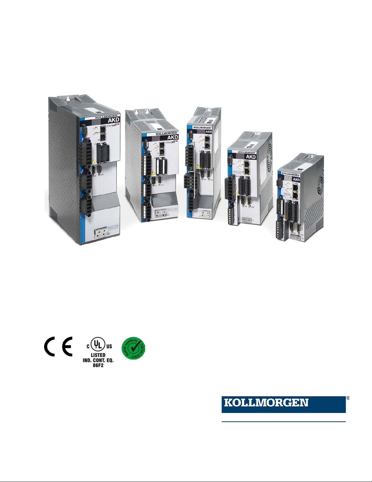
AKD™
Installation Manual
Edition March 2010
Valid for Hardware Revision A
Original Document
Patents Pending
Keep all manuals as a product component
during the life span of the product. Pass all manuals to
future users/owners of the product.
Page 2

Record of Document Revisions:
Revision Remarks
11/2009 Beta launch version
12/2009 Digital I/O corrections, several updates
03/2010
CAN terminationconnector "optional", data dynamic brake updated, resolver signals renamed,
CE certificate, X9 description updated, technical data completed
Hardware Revision (HR)
Hardware Revision Firmware WorkBench Remarks
A M_01-02-00-000 1.2.0
EnDat is a registered trademark of Dr. Johannes Heidenhain GmbH
EtherCAT is a registered trademark of EtherCAT Technology Group
HIPERFACE is a registeredtrademark of Max Stegmann GmbH
WINDOWS is a registeredtrademark of Microsoft Corporation
AKD is a registered trademark of Kollmorgen Corporation
Current patents:
US Patent 5,646,496 (used in control card R/D and1 Vp-p feedback interface)
US Patent 5,162,798 (used in control card R/D)
US Patent 6,118,241 (used in control card simple dynamic braking)
Technical changes which improve the performance of the device may be made without prior notice!
Printedin the United States of America
This document is the intellectual property of Kollmorgen™. All rights reserved. No part of this work may be
reproduced in any form (by photocopying, microfilm or any other method) orstored, processed, copied or distributed by electronic means without the written permission of Kollmorgen™.
2 Kollmorgen | March 2010
Page 3

Table of Contents
1 General 11
1.1 About this Manual 12
1.2 Target Group 12
1.3 Using the PDF Format 12
1.4 Abbreviations 13
1.5 Warning Symbols 14
1.6 Standards Used 15
2 Safety 16
2.1 Safety Instructions 17
2.2 Use as Directed 18
AKD Installation|
2.3 ProhibitedUse 18
3 Approvals 19
3.1 Conformance with UL/cUL 20
3.1.1 UL Markings 20
3.2 CE Conformance 22
3.2.1 EuropeanDirectives and Standards for the machinebuilder 23
3.2.2 EC Declaration of Conformity 24
3.3 Safe TorqueOff (STO) 25
4 Handling 26
4.1 Transport 27
4.2 Packaging 27
4.3 Storage 27
4.4 Maintenance andCleaning 28
4.5 Uninstalling 28
4.6 Repair and Disposal 28
5 Package 29
5.1 Package Supplied 30
5.2 Nameplate 30
5.3 Part numberscheme 31
6 Technical description and data 32
Kollmorgen | March 2010 3
Page 4

AKD Installation|
6.1 The AKD Family of Digital Drives 33
6.2 Ambient Conditions, Ventilation, and Mounting Position 35
6.3 Mechanical Data 35
6.4 Inputs/Outputs 36
6.5 Electrical Data AKD-xzzz06 37
6.6 Electrical Data AKD-xzzz07 38
6.7 Performance Data 39
6.8 Recommended tightening torques 39
6.9 Fusing 40
6.9.1 External Power Supply fusing 40
6.9.2 External 24 V supply fusing 40
6.9.3 External Brake Resistor fusing 40
6.10 Connectors 41
6.10.1 AKD-xzzz06 Types (120V to 240V Mains Voltage Supply) 41
6.10.2 AKD-xzzz07 Types (240V to 480V Mains Voltage Supply) 41
6.11 Cable and Wire Requirements 42
6.11.1 General 42
6.11.2 Cable Cross Sections and Requirements 42
6.12 LED display 43
6.13 Grounding System 43
6.14 Dynamic Braking 44
6.14.1 Functional description 44
6.14.2 Technical Data for AKD-xzzz06 45
6.14.3 Technical Data for AKD-xzzz07 46
6.15 Switch-on and Switch-off Behavior 47
6.15.1 Behavior in Standard Operation 48
6.15.2 Behavior in the event of a fault (with standard setting) 49
6.16 Stop-/Emergency Stop- Function 50
6.16.1 Stop: Standards 50
6.16.2 Emergency Stop: Standards 51
6.16.3 Implementation of the Stop Category 0 52
6.16.4 Implementation of Stop Category 1 53
4 Kollmorgen | March 2010
Page 5

AKD Installation|
6.16.5 Implementation of Stop Category 2 54
6.17 Safe Torque Off (STO) 55
6.17.1 Safety instructions 56
6.17.2 Use as directed 56
6.17.3 Prohibited Use 57
6.17.4 Technical data and pinning 57
6.17.5 Enclosure 57
6.17.6 Wiring 57
6.17.7 Functional description(in process) 58
6.17.7.1 Signal diagram (sequence) 59
6.17.7.2 Control circuit (example) 60
6.17.7.3 Functional test 61
6.17.7.4 Mains supply circuit (example) 61
6.18 Shock-hazard Protection 62
6.18.1 LeakageCurrent 62
6.18.2 Residual Current Protective Device (RCD) 62
6.18.3 Isolating Transformers 63
7 Mechanical Installation 64
7.1 Safety Instructions 65
7.2 Guide to Mechanical Installation 65
7.3 Control Cabinet Layout AKD-xzzz06 66
7.4 Control Cabinet Layout AKD-xzzz07 67
7.5 Dimensions, AKD-x00306 to x00606 68
7.6 Dimensions, AKD-x01206 69
7.7 Dimensions, AKD-x02406 70
7.8 Dimensions, AKDx00307 to 01207 71
7.9 Dimensions, AKDx02407 72
8 Electrical Installation 73
8.1 Safety Instructions 74
8.2 Guide to electrical installation 75
8.3 Wiring 76
8.4 Components of a servosystem 77
Kollmorgen | March 2010 5
Page 6

AKD Installation|
8.5 Connector Assignments, AKD-x00306 to x00606 78
8.6 Connector Assignments, AKD-x01206 78
8.7 Connector Assignments, AKD-x02406 andAKD-xzzz07 79
8.8 Connection Diagram, AKD-x00306 to x00606 80
8.9 Connection Diagram, AKD-x01206 81
8.10 Connection Diagram, AKD-x02406and AKD-xzzz07 82
8.11 EMI Noise Reduction 83
8.11.1 Recommendations for EMI Noise Reduction 83
8.11.2 Shielding with External Shielding Busbar 84
8.11.2.1 Shielding Concept 84
8.11.2.2 Shielding Busbar 85
8.11.3 Shielding Connection to the Drive 86
8.11.3.1 Grounding Plates 86
8.11.3.2 Shieldconnection clamps 86
8.11.3.3 MotorConnector X2 with shieldingconnection 87
8.12 Electrical Supply Connection 88
8.12.1 Connection to Various Mains Supply Networks AKD-xzzz06 (120V to 240V) 88
8.12.2 Connection to Various Mains Supply Networks AKD-xzzz07 (240V to 480V) 89
8.12.3 24 V Auxiliary Supply (X1) 90
8.12.4 Mains Supply Connection (X3, X4) 91
8.12.4.1 Three Phase connection (all AKD types) 91
8.12.4.2 Singlephase connection (AKD-xzzz06 only) 92
8.12.5 External Brake Resistor (X3) 93
8.12.6 DC Bus Link (X3) 94
8.13 Motor Connection 96
8.13.1 Motor Power (X2) 97
8.13.1.1 Cable Length ≤ 25 m 97
8.13.1.2 Cable length >25 m 97
8.13.2 Motor Holding Brake (X2) 98
8.14 Feedback Connection 99
8.14.1 Feedback Connector (X10) 100
8.14.2 Resolver 101
6 Kollmorgen | March 2010
Page 7

AKD Installation|
8.14.3 SFD 102
8.14.4 Encoder with BiSS 103
8.14.5 Sine Encoder with EnDat 2.1 104
8.14.6 Encoder with EnDat 2.2 105
8.14.7 Sine Encoder with Hiperface 106
8.14.8 Sine Encoder with Hall Encoder 107
8.14.9 Incremental Encoder with Hall Switches 108
8.15 Encoder Emulation Connector (X9) 109
8.15.1 Input Modes 109
8.15.1.1 Pinout Input X9 109
8.15.1.2 Pulse/Direction input (5 V) 110
8.15.1.3 Up/Down input (5 V) 111
8.15.1.4 Incremental Encoder (A quadB and Index) input (5 V) 111
8.15.2 Output Modes 112
8.15.2.1 Pinout Output X9 112
8.15.2.2 Emulated Encoder Output (EEO) - A quad B 113
8.15.3 Master-Slave Control 114
8.16 I/O Connection 115
8.16.1 I/O Connectors (X7 and X8) 115
8.16.2 Analog Input (X8) 116
8.16.3 Analog Output (X8) 117
8.16.4 Digital Inputs (X7/X8) 118
8.16.4.1 Digital Inputs 1 and 2 120
8.16.4.2 Digital Inputs 3 to 7 120
8.16.4.3 Digital Input 8 (ENABLE) 120
8.16.5 Digital Outputs (X7/X8) 121
8.16.5.1 Digital Outputs 1 and2 121
8.16.5.2 FAULT relay contacts 122
8.17 Service Interface (X11) 123
8.17.1 Possible Network Configurations 123
8.17.2 Setting the IP Address with Rotary Switches 124
8.18 CANbus Interface (X12/X13) 125
Kollmorgen | March 2010 7
Page 8

AKD Installation|
8.19 Motion Bus Interface (X5/X6) 129
8.18.1 Transmission Rate for CANbus 125
8.18.2 Node Address for CANbus 126
8.18.3 CANbus Termination 126
8.18.4 CAN Bus Wiring 127
8.18.5 CANbus Cable 128
8.19.1 Pinout X5/X6 129
8.19.2 Optional Motion Bus Protocols 129
8.19.3 EtherCAT 130
8.19.4 SynqNet (in process) 130
8.19.5 Motion Busses in Process 130
8.19.5.1 PROFINET CBA/RT/IRT (in process) 130
8.19.5.2 SERCOS III (in process) 130
8.19.5.3 Ethernet IP (A-B, in process) 130
8.19.5.4 Powerlink (in process) 130
8.19.5.5 Modbus TCP/IP (in process) 130
9 Setup 131
9.1 Safety Instructions 132
9.2 Setup software (WorkBench) 133
9.2.1 Use as directed 133
9.2.2 Software description 134
9.2.3 Hardware requirements 134
9.2.4 Operating systems 134
9.2.5 Installation under WINDOWS 2000/XP/VISTA/7 135
9.3 Basic Drive Test 136
9.3.1 Unpacking, Mounting, andWiring the Drive 136
9.3.2 Minimum Wiring for Drive Test without Load 136
9.3.3 Testing Procedure 137
9.3.3.1 Confirm Connections 137
9.3.3.2 Install and Start WorkBench 137
9.3.3.3 Set Drive IP Address in WorkBench 138
9.3.3.4 Enable the Drive Using the Setup Wizard. 138
8 Kollmorgen | March 2010
Page 9

AKD Installation|
9.4 Fault and Warning Messages 139
9.5 Troubleshooting the AKD 146
10 Option Cards 147
11 Order Codes 148
11.1 Cables, brake resistors, filters, chokes 148
11.2 Drives 148
11.3 Mating connectors 148
11.3.1 AKD-xzzz06 148
11.3.2 AKD-xzzz07 148
12 Index 149
Kollmorgen | March 2010 9
Page 10

This page intentionally left blank.
10 Kollmorgen | March 2010
Page 11

AKD Installation| 1 General
1 General
1.1 About this Manual 12
1.2 Target Group 12
1.3 Using the PDF Format 12
1.4 Abbreviations 13
1.5 Warning Symbols 14
1.6 Standards Used 15
Kollmorgen | March 2010 11
Page 12

AKD Installation| 1 General
1.1 About this Manual
This manual, AKD Installation Manual, describes the AKD series of digital drives and includes information
needed to safely install an AKD. A digital version of this manual (pdf format) is available on the CD-ROM
included with your drive. Manual updates can be downloaded from the Kollmorgen website (www.kol-
lmorgen.com).
This document fulfills all requirements for an "Instructions Manual" underthe EC Machinery Directive
(2006/42/EC).
Additional documents on the accompanying CD-ROM include the following:
l AKD Quick Start (also provided in hardcopy). This guide provides instructions for basic drive setup
andconnection to a network.
l AKD Users Manual. This manual describes how to use your drive in common applications. It also pro-
vides tips for maximizing your system performance with the AKD.
l AKD Parameter and Command Reference Guide. This guide provides documentationfor the param-
eters andcommands used to program the AKD.
l AKD Accessories Manual. This manual includes technical data anddimensional drawings of acces-
sories such as cables, brake resistors, andmains supplies.
1.2 Target Group
This manual addresses personnel with the following qualifications:
l Transport: only by personnel with knowledge of handling electrostatically sensitive components.
l Unpacking: only by electrically qualified personnel.
l Installation: only by electrically qualified personnel.
l Basic tests: only by qualified personnel with extensive knowledge of electrical engineering and drive
technology
The qualified personnel must know and observe the following standards:
l ISO 12100, IEC 60364 andIEC 60664
l National accident preventionregulations
During operation, hazards exist that can cause death, severe injury, or material
damage. To safely operate the AKD, you must follow all safety instructions in
this manual. The operator of systems using the AKD must require that all personnel who work with the drive read and understand the manual before using the
drive.
1.3 Using the PDF Format
This document includes several features for ease of navigation
Cross References Table of contents and index include active cross references.
Table of contents and index Lines are active cross references. Click on the line andthe appropriate page
Page/chapter numbers in
the text
12 Kollmorgen | March 2010
is accessed.
Page/chapternumbers with cross references are active links.
Page 13

1.4 Abbreviations
Abbreviation Meaning
AGND Analog ground
CE Communité Européenne
COM Serial interface for a personal computer
DCOMx Communication line for digital inputs (with x=7 or 8)
Disk Magnetic storage (diskette, hard disk)
EEPROM Electrically erasable programmable memory
EMC Electromagnetic compatibility
F-SMA Fiber optic cable connector according to IEC 60874-2
LED Light-emitting diode
LSB Low significant byte (orbit)
MSB Main significant byte (or bit)
NI Zero pulse
PC Personal computer
PE Protective earth
PLC Programmable logic control
PWM Pulse-width modulation
RAM Random access memory (volatile memory)
R
Brake/RB
RBext External brake resistor
RBint Internal brake resistor
RCD Residual current device
RES Resolver
ROD Incremental encoder (A quad B)
S1 Continuous operation
STO Safe torque off
Vac Volts, alternating current
Vdc Volts, direct current
Brake resistor (also called a regen resistor)
AKD Installation| 1 General
Kollmorgen | March 2010 13
Page 14
AKD Installation| 1 General
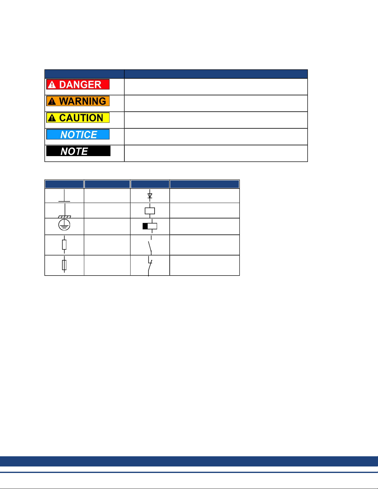
1.5 Warning Symbols
Symbol Indication
Drawing symbols
Symbol Description Symbol Description
Signal ground Diode
Indicates a hazardous situation which, if not avoided, will result in
death or serious injury.
Indicates a hazardous situation which, if not avoided, could result in
death or serious injury.
Indicates a hazardous situation which, if not avoided, could result in
minor or moderate injury.
Indicates situations which, if not avoided, couldresult in property
damage.
This is not a safety symbol.
This symbol indicates important notes.
Chassis ground Relays
Protective earth Relays switch off
delayed
Resistor Normal open contact
Fuse Normal closed contact
14 Kollmorgen | March 2010
Page 15

AKD Installation| 1 General
1.6 Standards Used
Standard Content
ISO 4762 Hexagon socket head cap screws
ISO 11898 Road vehicles — Controller area network (CAN)
ISO 12100 Safety of machinery: Basic concepts, general principles for design
ISO 13849 Safety of machinery: Safety-related parts of control systems
IEC 60085 Electrical insulation - Thermal evaluation anddesignation Maintenance
IEC 60204 Safety of Machinery: Electrical equipment of machinery
IEC 60364 Low-voltage electrical installations
IEC 60439 Low-Voltage Switchgear and Controlgear Assemblies
IEC 60529 International protection rating (IP code)
IEC 60664 Insulationcoordinationfor equipment within low-voltage systems
IEC 60721 Classification of environmental conditions
IEC 61000 Electromagnetic compatibility (EMC)
IEC 61131 Programmable controllers
IEC 61491 Electrical equipment of industrial machines – Serial data link for real-time com-
munications between controls anddrives.
IEC 61508 Functional safety of electrical/electronic/programmableelectronic safety-related sys-
tems
IEC 61800 Adjustable speed electrical power drive systems
IEC 62061 Functional safety of electrical/electronic/programmableelectronic safety-related sys-
tems
IEC 62079 Preparationof instructions - Structuring, content and presentation
ANSI Z535 Product safety (symbols, colors, information)
UL 840 UL Standard for Safety for InsulationCoordination Including Clearances and Creep-
ageDistances for Electrical Equipment
UL 508C UL Standard for Safety Power Conversion Equipment
ANSI - AmericanNational StandardInstitute, Inc.
IEC - International Electrotechnical Commission
ISO - International Organizationfor Standardization
UL - Underwriters Laboratories
Kollmorgen | March 2010 15
Page 16

AKD Installation| 2 Safety
2 Safety
2.1 Safety Instructions 17
2.2 Use as Directed 18
2.3 Prohibited Use 18
16 Kollmorgen | March 2010
Page 17

2.1 Safety Instructions
Duringoperation, hazards exist that can cause death, severe injury, or material
damage. Do not open or touch the equipment during operation. Keep all covers
andcabinet doors closed during operation. Only properly qualified persons may
handle the equipment during installation and commissioning .
l Duringoperation, drives may have uncovered live components, depend-
ing on their level of enclosureprotection.
l Control and power connections may be live, even though the motoris not
rotating.
l Drives may have hot surfaces during operation. The heat sink can reach
temperatures above 80°C.
The danger of electrical arcing is present. Electrical arcing can damage contacts and injure personnel. Never undo any electrical connections to the drive
while it is live.
Wait at least 7 minutes after disconnecting the drive from the main supply
powerbefore touching potentially live sections of the equipment (such as contacts) or removing any connections.
Capacitors can have dangerous voltages present up to seven minutes after
switching off the supply power. Always measurethe voltagein the DC bus link
andwait until the voltage is below 40 V before handling components.
Incorrect handling of the drive can lead to personnel injury or material damage.
Read this documentation before installing and commissioning the drive. It is
vital that you keep to the technical data and information on connection requirements (nameplate and documentation).
Only properly qualified personnel may perform activities such as transport,
installation, commissioning, andmaintenance. Properly qualified persons are
those who are familiar with the transport, assembly, installation, commissioning
andoperation of the product, and who have the appropriate qualifications for
their job. The qualified personnel must know and observe the following standards:
AKD Installation| 2 Safety
l IEC 60364 and IEC 60664
l national accident preventionregulations
The manufacturer of the machine must produce a hazard analysis for the
machine and take appropriate measures to ensure that unforeseen movements
do not result in personnel injury or material damage.
It is not allowed to modify this device without permission by the manufacturer.
Check the Hardware Revision Number of the product (see product label). This
revision number must match the Hardware Revision Number on the cover page
of the manual.
The drives contain electrostatically sensitive components which may be damaged by incorrect handling. Electrostatically discharge your body before touching the drive. Avoid contact with highly insulating materials (artificial fabrics,
plastic film etc.). Place the drive on a conductive surface.
Kollmorgen | March 2010 17
Page 18

AKD Installation| 2 Safety
2.2 Use as Directed
Drives arecomponents that are built into electrical plants or machines and can only be operated as integral
components of these plants or machines. The manufacturer of the machine used with a drive must generate a
hazard analysis for the machine and take appropriate measures to ensure that unforeseen movements cannot
cause personnel injury or property damage.
Cabinet and wiring
Drives must only be operated in a closed control cabinet suitablefor the ambient conditions see page 32. Ventilation or coolingmay be necessary to keepthe temperaturewithin the cabinet below 40 °C.
Use only copper conductors for wiring. The conductor cross-sections can be derived from the standard IEC
60204 (alternatively for AWG cross-sections: NEC Table 310-16, 75 °C column).
Power supply
Drives in the AKD series can be supplied as follows:
l AKD-xzzz06: 1 or 3 phase industrial supply networks
(not more than 42 kA symmetrical rated current at 120 V and 240 V).
l AKD-xzzz07: 3 phase industrial supply networks
(not more than 42 kA symmetrical rated current at 240 V, 400 V and 480 V).
Connection to other voltage types of supply networks is possible with an additional isolating transformer (see
page 88).
Periodic overvoltages between phases (L1, L2, L3) and the housing of the drive must not exceed 1000V peak.
In accordance with IEC 61800, voltage spikes (< 50 µs) between phases must not exceed 1000 V. Voltage
spikes (< 50 µs) between a phase and the housing must not exceed 2000 V.
EMC filter measures must be implemented by the user.
Motor voltage rating
The AKD family of drives is exclusively intended for driving suitable synchronous servomotors with closedloopcontrol of torque, speed, and/or position. The rated voltage of the motors must be at least as high as the
DC bus link voltage divided by √2 producedby the drive (U
nMotor
>=UDC/√2).
Safe torque off and restart lock
Review the section "Use as Directed" in the safe torqueoff (STO) chapter (see page56) before using the personnel safe restart lock (accordingto ISO 13849 category 3).
2.3 Prohibited Use
Otheruse than that described in chapter “Use as directed” is not intended andcan lead to personnel injuries
andequipment damage. The drive may not be used with a machine that does not comply with appropriate
national directives or standards. The use of the drive in the following environments is also prohibited:
l potentially explosive areas
l environments with corrosive and/orelectrically conductive acids, alkaline solutions, oils, vapors, dusts
l ships or offshore applications
18 Kollmorgen | March 2010
Page 19

AKD Installation| 3 Approvals
3 Approvals
3.1 Conformance with UL/cUL 20
3.2 CE Conformance 22
3.3 Safe Torque Off (STO) 25
Kollmorgen | March 2010 19
Page 20

AKD Installation| 3 Approvals
3.1 Conformance with UL/cUL
This drive is listed under UL (Underwriters Laboratories Inc.) file number E141084 Vol.3 Sec.5.
USL, CNL – Power conversion equipment (NMMS, NMMS7) – Models AKD followed by B,P,S,M or F, followed by 003, 006, 012, and024, followedby 06 or 07, followed by additional suffixes.
USL
Indicates Investigated to United States Standard for Power Conversion Equipment, UL 508C, Third Edition,
Revised February 15, 2008.
CNL
Indicates investigation to Canadian Standard for Industrial Control Equipment, CAN/CSA - C22.2 No. 142005, Second Edition, Revised April 2008.
Note:
CNL = Canadian National Standards - Listed.
USL = United States Standards - Listed.
3.1.1 UL Markings
l These drives are open type adjustable frequency motor drives that providevariable speed control to
motors andprovides overload protection andcurrent limit control.
l These devices are intended to be used in a pollution degree2 environment.
l Identification of the terminals on the controller are codedso they may be identified in the instructions.
The instructions shall identify powerconnections for power supply, load, control, and ground.
l Integral solid state short circuit protection does not provide branch circuit protection. Branch circuit pro-
tection must be provided in accordance with the National Electrical Code and any additional local
codes, or the equivalent.
l This product is suitable for use on a circuit capable of delivering not more than 200,000rms sym-
metrical amperes, 240 V (AKD-xzzz06) / 480 V (AKD-xzzz07) volts maximum, when protected by ”
Fuses", or equivalant.
l The following fuse types arerecommended:
Model Fuse class Rating Max. Fuse Rating
AKD-x00306 J 600 Vac, 200 kA 10 A
AKD-x00606 J 600 Vac, 200 kA 15 A
AKD-x01206 J 600 Vac, 200 kA 15 A
AKD-x02406 J 600 Vac, 200 kA 30 A
AKD-x00307 J 600 Vac, 200 kA 6 A
AKD-x00607 J 600 Vac, 200 kA 10 A
AKD-x01207 J 600 Vac, 200 kA 15 A
AKD-x02407 J 600 Vac, 200 kA 30 A
l These drives provide solid state motor overload protection at 125% of the rated FLA Current.
l Use minimum 75°C copper wire.
20 Kollmorgen | March 2010
Page 21

AKD Installation| 3 Approvals
l The following tableillustrates the torque requirements for the field wiring connectors:
Model Mains Connector Motor Phase Connector 24 Vdc Input Connector
AKD-x00306 5-7in-lbs 5-7 in-lbs 4 in-lbs
AKD-x00606 5-7in-lbs 5-7 in-lbs 4 in-lbs
AKD-x01206 5-7in-lbs 7 in-lbs 4 in-lbs
AKD-x02406 7 in-lbs 7 in-lbs 4 in-lbs
AKD-x00307 7 in-lbs 7 in-lbs 4 in-lbs
AKD-x00607 7 in-lbs 7 in-lbs 4 in-lbs
AKD-x01207 7 in-lbs 7 in-lbs 4 in-lbs
AKD-x02407 7 in-lbs 7 in-lbs 4 in-lbs
l Maximum surrounding air temperature of 40°C” or equivalent.
Kollmorgen | March 2010 21
Page 22
AKD Installation| 3 Approvals
3.2 CE Conformance
Conformance with the EC EMC Directive 2004/108/EC and the Low Voltage Directive 2006/95/EC is mandatory for the supply of drives within the European Community.
The drives have been tested by an authorized testing laboratory in a defined configuration, using the system
components that are described in this documentation. Any divergence from the configuration and installation
described in this documentationmeans that the user will be responsiblefor carrying out new measurements to
ensure conformance with regulatory requirements.
AKD-xzzz06
With external EMC filters for noise emission the drives meet the noise immunity requirements of the second
environmental category (industrial environment) to a product of the category C2 (motor cable < 10 m).
Withamotorcablelengthof10morlongerandexternalEMC filters,thedrivemeetstherequirementofcategoryC3.
AKD-xzzz06 drives do not have integrated EMC filters. These drives can cause
high-frequency interferences and may require measures for interference suppression (such as additional external EMC filters).
AKD-xzzz07
AKD-xzzz07 drives have integrated EMC filters.
The drive meets the noise immunity requirements to the 2nd environmental category (industrial environment).
For noise emission the drive meets the requirement to a product of the Category C2 (motor cable < 10 m).
With a motor cable length of 10 m or longer, the servo drive meets the requirement to the Category C3.
22 Kollmorgen | March 2010
Page 23
AKD Installation| 3 Approvals
3.2.1 European Directives and Standards for the machine builder
Drives arecomponents that are intendedto be incorporated into electrical plant and machines for industrial
use. Whenthe drives are built into machines or plant, the drive must not be used until it has been established
that the machine or equipment fulfills the requirements of the
l EC Machinery Directive (2006/42/EC)
l EC EMC Directive (2004/108/EC)
l EC Low Voltage Directive (2006/95/EC)
Standards to be applied for conformance with the EC Machinery Directive (2006/42/EC)
l IEC 60204-1 (Safety and Electrical Equipment in Machines)
l ISO 12100(Safety of Machines)
The manufacturer of the machine must generate a hazard analysis for the
machine, and must implement appropriate measures to ensure that unforeseen
movements cannot cause injury or damage to any person or property.
Standards to be applied for conformance with the EC Low VoltageDirective(2006/95/EC)
l IEC 60204-1 (Safety and Electrical Equipment in Machines)
l IEC 60439-1 (Low-voltage switchgear and controlgear assemblies)
Standards to be applied for conformance with the EC EMC Directive (2004/108/EC)
l IEC 61000-6-1/2 (Interference Immunity in Residential & Industrial Areas)
l IEC 61000-6-3/4 (Interference Generation in Residential & Industrial Areas)
The manufacturer of the machine/plant is responsible for ensuring that it meets the limits required by the EMC
regulations. Advice on the correct installation for EMC (such as shielding, grounding, treatment of connectors
andcable layout) is shown in this manual.
The machine/plant manufacturer must check whether other standards or EC Directives must be applied to the machine/plant.
Kollmorgen only guarantees the conformance of the servosystem with the standards cited in this chapter if the
components (motor, cables, chokes etc.) are those supplied by Kollmorgen.
Kollmorgen | March 2010 23
Page 24
AKD Installation| 3 Approvals
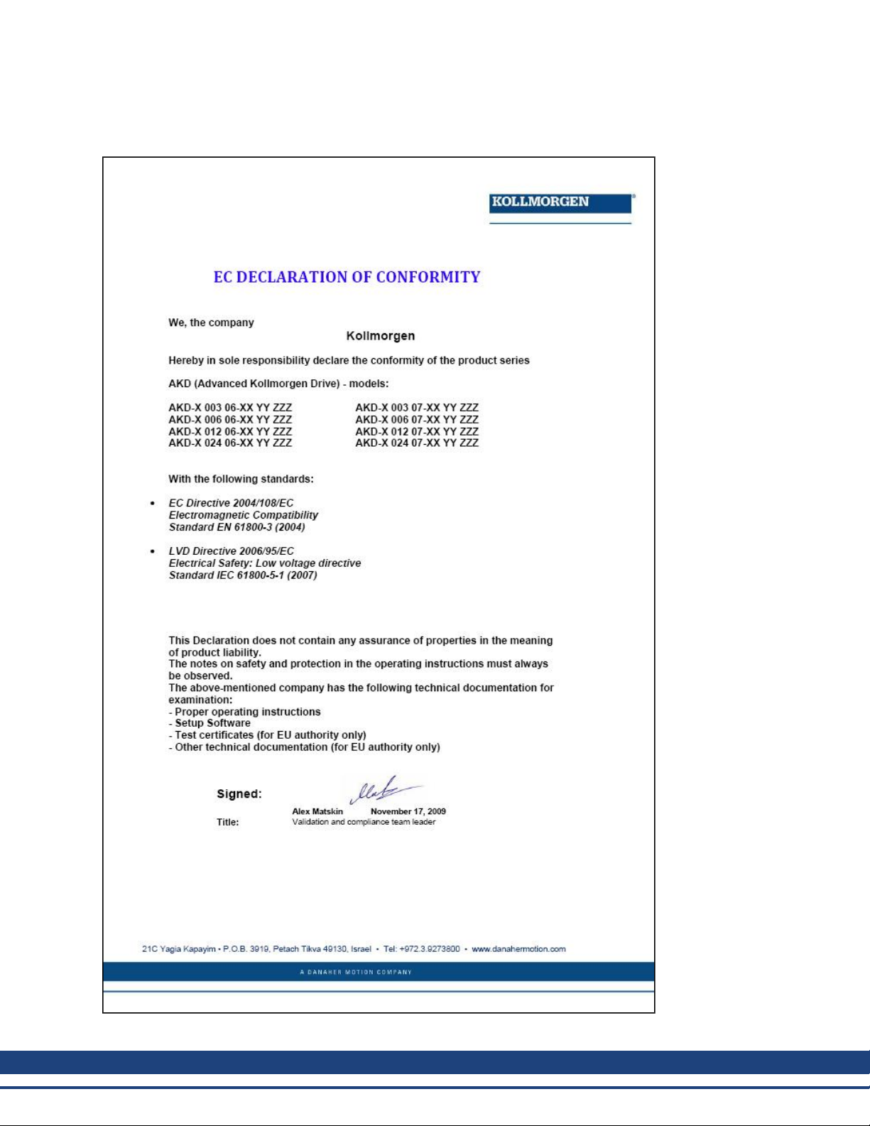
3.2.2 EC Declaration of Conformity
24 Kollmorgen | March 2010
Page 25

AKD Installation| 3 Approvals
3.3 Safe Torque Off (STO)
STO Input X1/3
TheAKD drive’s STO functionality is not certified, yet. The circuit concept is going to be examinedby theTÜV.
We cannot ensure the functionality of the STO function until the certification
process is complete.
We expect theSTO functionality certified in July 2010.To ensureproduct is certified, pleasecontact Kollmorgenfor updatedinformation. Connect the STO input X1/3 with +24Vdc. This deactivates theSTO function.
STO Eingang X1/3
Die STO Funktionalität des AKD Servoverstärkers ist nicht zertifiziert. Das Schaltungskonzept wird zur Zeit
vom TÜV geprüft.
Bis zum Abschluss der Prüfung können wir die Funktionalität der STO Funktion
nicht gewährleisten.
Wir erwarten dieZertifizierung der STO Funktionalität im Juli 2010. Setzen Sie sich mit Kollmorgenfür
aktuelle Informationen zur Zertifizierung in Verbindung. Verbinden Sie den STO Eingang X1/3 fest mit +24
VDC. Dies deaktiviert die STO Funktion.
Ingresso STO X1/3
La funzionalità STO del servoazionamento AKD non è ancora certificata. Il principio di collegamento verrà
esaminato dal TÜV.
Fino a quando non sarà concluso il procedimento di certificazione non possiamo garantire la funzionalità della funzione STO.
La certificazione della funzionalità STO è prevista per il mese di luglio 2010. Per accertarsi che il prodotto sia
certificato, metta in contatto con Kollmorgen per riceverele informazioni aggiornate. Collegare l'ingresso STO
X1/3 a +24 Vdc. In questo modo la funzione STO viene disattivata.
Entrée STO X1/3
La fonctionnalité STO du variateur AKD n’est pas encore certifiée. Le concept du circuit va être examinépar le
TÜV.
Nous ne pouvons garantir la fonctionnalité pour la fonction STO, tant que le
processus de certification n’est pas achevé.
Nous prévoyons que la fonctionnalité STO sera certifiée en juillet 2010. Pours'assurer quele produit est certifié, entrez en contact avec Kollmorgen pour l'information mise à jour. Connectez l’entrée STO X1/3 avec +24
Vcc. Ceci désactive la fonction STO.
Kollmorgen | March 2010 25
Page 26

AKD Installation| 4 Handling
4 Handling
4.1 Transport 27
4.2 Packaging 27
4.3 Storage 27
4.4 Maintenance and Cleaning 28
4.5 Uninstalling 28
4.6 Repair and Disposal 28
26 Kollmorgen | March 2010
Page 27
AKD Installation| 4 Handling
4.1 Transport
Transport the AKD in accordance with IEC 61800-2 as follows:
l Transport only by qualified personnel in the manufacturer’s original recyclable packaging.
l Avoid shocks while transporting.
l Transport only within specified temperature ranges: -25 to +70 °C, max. rate of change20 K/hour,
class 2K3.
l Transport only within specifiedhumidity: max. 95% relative humidity, no condensation, class 2K3.
The drives contain electrostatically sensitive components that can be damaged
by incorrect handling. Electrostatically discharge yourself before touching the
drive. Avoid contact with highly insulating materials, such as artificial fabrics
and plastic films. Place the drive on a conductive surface.
If the packagingis damaged, check the unit for visible damage. Inform the shipperand the manufacturer of
any damage to the package or product.
4.2 Packaging
The AKD packaging consists of recyclable cardboard with inserts and a label on the outside of the box.
Model
Package Dimensions (mm)
HxWxL
Total Weight (kg)
AKD-x00306 and AKD-x00606 77 x 280 x 222 1.7
AKD-x01206 153x 394x 229 3.4
AKD-x02406 153x 394x 229 5
AKD-x00307 and AKD-x00607 153x 394x 229 4.3
AKD-x01207 153x 394x 229 4.3
AKD-x02407 153x 394x 229 6.7
4.3 Storage
Store the AKD in accordance with IEC 61800-2 as follows:
l Store only in the manufacturer’s original recyclable packaging.
l Store at or below maximum stacking height:
l AKD-x0306to 0606 models: 8 cartons
l All other models: 6 cartons
l Store only within specified temperature ranges: -25to +55 °C, max.rate of change 20 K/hour, class
1K4.
l Storage only within specified humidity: 5 to 95% relative humidity, no condensation, class 1K3.
l Store in accordance with the following duration requirements:
l Less than 1 year: without restriction.
l More than 1 year: capacitors must be re-formed before setting up and operating the drive. To re-
form the capacitors, remove all electrical connections andapply single-phase 120 Vac for about 30
minutes to the L1/L2 terminals.
Kollmorgen | March 2010 27
Page 28
AKD Installation| 4 Handling
4.4 Maintenance and Cleaning
The drive does not require maintenance. Opening the drive voids the warranty.
The inside of the unit can only be cleaned by the manufacturer. To clean the drive exterior:
l Casing: Cleanwith isopropanol or similar cleaningsolution.
l Protective grill on fan: Clean with a dry brush.
4.5 Uninstalling
If a drive must be uninstalled (such as for replacement), remove the drive as follows:
1. Switch off the main switch of the switchgear cabinet andthe fuses that supply the system.
Do not immerse or spray the drive.
Wait at least seven minutes after disconnecting the drive from the main supply
power before touching potentially live sections of the equipment (e.g. contacts)
or undoing any connections. Always measure the voltage in the DC bus link and
wait until the voltage is below 40 V before touching or handling the drive.
2. Remove the connectors. Disconnect the potential earth connection last.
3. Check temperature.
During operation, the heat sink of the drive may reach temperatures above 80°C
(176°F). Before touching the device, check the temperature and wait until it has
cooled below 40°C (104°F).
4. Uninstall. Remove the drive andpower supply from the conductive, grounded mounting plate in the cabinet.
4.6 Repair and Disposal
Onlythe manufacturercan repairthe drive.Opening thedevice voidsthe warranty. Uninstall the drive as
describedin "Uninstalling" (page28)andsend it in theoriginal packagingto themanufacturer (seetable below).
In accordance with the WEEE-2002/96/EC-Guidelines andsimilar, the manufactureraccepts returns of old
devices and accessories for professional disposal. Transport costs are the responsibility of the sender. Send
the devices to the manufacturer addresses shown in the table below.
USA Europe
Kollmorgen
201West Rock Road
Radford, VA 24141
DanaherMotion GmbH
Wacholderstr. 40-42
D-40489Düsseldorf
28 Kollmorgen | March 2010
Page 29

AKD Installation| 5 Package
5 Package
5.1 Package Supplied 30
5.2 Nameplate 30
5.3 Part number scheme 31
Kollmorgen | March 2010 29
Page 30

AKD Installation| 5 Package
5.1 Package Supplied
WhenadrivefromtheAKD seriesis ordered(seepage148), thefollowingitemsareincludedinthedrivepackage:
l AKD drive
l Printedcopy of AKD Installation Manual (EU only)
l Printedcopy of AKD Quick Start
l Printedcopy of fault and warning card
l CD-ROM containing the setup software, WorkBench, and all product documentation in digital format.
l Mating connectors X1, X2, X3, X4 (if required), X7, andX8
l Grounding plate, L-shape or Flat depending on AKD voltage tye
Accessories Sold Separately
Accessories must be orderedseparately if required; refer to your regional accessories manual:
l EMC filters for 24 V andmains supply voltage, categories C2 or C3
l External brake resistor
l Motor cable. Assembled motor cables are available for all regions. EU customers may also order motor
cable at custom lengths and assemble the cable with power connectors ordered separately.
l Feedback cable. Assembled feedback cables areavailable for all regions. EU customers may also
orderfeedback cable at custom lengths and assemble the cablewith power connectors ordered separately.
l Motor choke, for motor cables longer than 25m
l CAN terminationconnector (with CAN drives only)
l Service cable to the network
l Power cable, control cables, and fieldbus cables (as cutoff lengths)
The mating SubD and RJ45 connectors are not included in the package.
5.2 Nameplate
The nameplate depicted below is attached to the side of the drive, sample data entries are for a 12A type.
30 Kollmorgen | March 2010
Page 31

5.3 Part number scheme
The part number is identical to the ordercode.
AKD Installation| 5 Package
Customization code includes language versionof printed material for Europeancountries:
l D000 for German
l E000 for English
l F000 for French
l I000 for Italian
Presently the AKD-xzzz07 models only support operation at levels above 270Vac. Updates to the AKD firmware are in process to allow the operation of the AKD-xzzz07 models drives at 240Vac. These updates will
only requirea firmware modification and will be backwards compatible with all AKD-xzzz07 hardware."
Kollmorgen | March 2010 31
Page 32

AKD Installation| 6 Technical description and data
6 Technical description and data
6.1 The AKD Family of Digital Drives 33
6.2 Ambient Conditions, Ventilation, and Mounting Position 35
6.3 Mechanical Data 35
6.4 Inputs/Outputs 36
6.5 Electrical Data AKD-xzzz06 37
6.6 Electrical Data AKD-xzzz07 38
6.7 Performance Data 39
6.8 Recommended tightening torques 39
6.9 Fusing 40
6.10 Connectors 41
6.11 Cable and Wire Requirements 42
6.12 LED display 43
6.13 Grounding System 43
6.14 Dynamic Braking 44
6.15 Switch-on and Switch-off Behavior 47
6.16 Stop-/Emergency Stop- Function 50
6.17 Safe Torque Off (STO) 55
6.18 Shock-hazard Protection 62
32 Kollmorgen | March 2010
Page 33

AKD Installation| 6 Technical description and data
6.1 The AKD Family of Digital Drives
Standard features
l Supply voltage range 95 Vac to 480 Vac ±10%.
l Several housingdimensions, dependingon current and hardware options.
l Motion bus onboard.
l TCP/IP service channel onboard.
l SFD, Resolver, Comcoder, 1Vp-p Sin-Cos encoders, incremental encoders support onboard.
l Support for ENDAT 2.1 & 2.2, BISS or HIPERFACE protocols onboard.
l Encoder emulation onboard.
l Secondfeedback support.
l Safe Torque Off (STO) according to IEC 61508 SIL 2 onboard.
l Use with Synchronous servomotors, linear motors, and induction machines can be used.
Available AKD versions
l B - Base drive is controlledby analog torque andvelocity commands (electronic gearing).
l P - Position Indexer drive adds the ability to command multiple motions, process I/O, make decisions,
addtime delays, andmodify drive process variables to the base drive.
l T - (in process) Structured Text drive adds simple programmability (similar to Basic) to the base drive.
l S - (in process) Single Axis KMS is a one-axis programmable drive features KMS software built in to
the drive. Includes all five IEC 61131 languages, PLC Open and Pipes Network.
l M - (in process) Multi Axis KMS master drive runs two to four axes. Includes all five IEC 61131lan-
guages, PLC Open and Pipes Network.
Power section
l Oneorthree phase supply, voltage range95to 480 V, 50/60 Hz.
l Connection to highervoltage mains only via isolatingtransformer, see page 89
l B6 bridge rectifier, integral soft-start circuit.
l Single phase supply possible with output power derating.
l Fusing to be provided by the user.
l Shielding star point close to the drive.
l DC bus link voltage range 120 to 375Vdc, can be connected in parallel.
l Output stage IGBT module with floatingcurrent measurement.
l Brake circuit with dynamic distribution of the generated power between several drives on the same
DC bus link circuit.
l Internal brake resistor for all 240/480 Vac AKD-xzzz07 models (only 120/240 Vac 3 A and 6 A AKD-
xzzz06 models lack internal brake resistors.), external brake resistors if required.
Kollmorgen | March 2010 33
Page 34

AKD Installation| 6 Technical description and data
Integrated safety
l Appropriate insulation/creepage distances and electrical isolation for safe electrical separation, per
IEC 61800-5-1, between the power input/motor connections and the signal electronics.
l Soft-start, overvoltage detection, short-circuit protection, phase-failure monitoring.
l Temperature monitoring of the drive and motor.
l Motor overload protection: foldback mechanism
l SIL 2 safe torque off in accordance with IEC 61508, see page 55.
l Optional safety functions for the safe operation of drive shafts in accordance with IEC 61800-5-2 (in
process).
Auxiliary supply voltage 24V DC
l From an external, safety approved24 V ±10% power supply.
Operation and parameter setting
l Using the setup softwareWorkBench, for setup via TCP/IP.
Full digital control
l Digital current controller (670 ns)
l Adjustabledigital velocity controller (62.5 µs)
l Software optionposition controller (125 µs)
Inputs/Outputs
l 1 programmable analog input see page 116
l 1 programmable analog output see page 117
l 7 programmable digital inputs see page 118
l 2 programmable digital outputs see page 121
l 1 Enableinput see page 118
l 1 STO input see page 55
Option Cards (in process)
Several option cards arein process. These options will affect the device width.
Connectivity
l Analog +/- 10 V control with encoder feedback output.
Onboard Serial Interface (see page 125), optional
l CANopen see page 125
Onboard Ethernet interface (see page129), optional
l SynqNet see page 129
l EtherCAT see page129
34 Kollmorgen | March 2010
Page 35

AKD Installation| 6 Technical description and data
6.2 Ambient Conditions, Ventilation, and Mounting Position
Storage see page 26
Transport seepage 26
Ambient temperature
in operation
Humidity in operation Relative humidity 5 to 85%, no condensation, class 3K3
Site altitude Up to 1000meters AMSL without restriction
Pollution level Pollution level 2 as per IEC 60664-1
Vibrations Class 3M1 according to IEC 60721-3-3
Enclosure protection IP 20 according to IEC 60529
Mounting position Vertical, see page 66
Ventilation Built-in fan
0 to +40 °C underrated conditions
+40 to +55 °C with continuous current derating 4 % per °C
1,000 to 2,500 meters AMSL with power derating 1.5%/100 m
The drive shuts down (fault F234, see page 139, motor has no
torque) in case of excessively high temperature in the control cabinet. Make sure sufficient forced ventilation is supplied within the
control cabinet.
AMSL = above mean sea level
6.3 Mechanical Data
Mechanical data Units AKD-x00306 AKD-x00606 AKD-x01206 AKD-x02406
Weight, standard kg 1.1 2 3.7
Weight, delivery package kg 1.7 3.4 5
Height, without connectors mm 168 195 250
Height, with service connector mm 200 225 280
Width front/back, standard mm 53/57 74/76 97/100
Depth, without connectors mm 153 186 230
Depth, with connectors mm < 205 < 255 <300
Mechanical data Units AKD-x00307 AKD-x00607 AKD-x01207 AKD-x02407
Weight, standard kg 2.7 5.3
Weight, delivery package kg 4.3 6.7
Height, without connectors mm 256 306
Height, with service connector mm 290 340
Width front/back, standard mm 65/70 100/105
Depth, without connectors mm 185 228
Depth, with connectors mm <225 <265
Kollmorgen | March 2010 35
Page 36

AKD Installation| 6 Technical description and data
6.4 Inputs/Outputs
Interface Electrical Data
Analog input (resolution16 bit) ±10Vdc
Max. common-mode voltage ±10 Vdc
Analog output (resolution 16 bit) ±10 Vdc
Digital inputs min. 3.5 Vdc, max. 30 Vdc
Digital outputs max. 30 Vdc, 100 mA
FAULT output, relay contacts max. 30 Vdc, max 42 Vac, 1 A
min. 2 mA, max. 15 mA
36 Kollmorgen | March 2010
Page 37

AKD Installation| 6 Technical description and data
6.5 Electrical Data AKD-xzzz06
Electrical Data Units AKD-x00306 AKD-x00606 AKD-x01206 AKD-x02406
Rated supply voltage, 50/60 Hz V~
Rated input powerfor S1 operation kVA 1.2 2.38 3.82 7.6
Rated input current
at 1x120 V A 5.0 9.9 12 N/A
at 1x240 V A 5.0 9.9 12 N/A
at 3x120 V A 2.3 4.6 9.2 N/A
at 3x240 V A 2.3 4.6 9.2 18.3
Permitted switch on/off frequency 1/h 30
Max. inrush current A 10 10 10 20
Rated DC bus link voltage
(Bus Turn onDelay 3ph 1 sec)
Continuous output current ( ± 3%)
at 120 V Arms 3 6 12 N/A
at 240 V Arms 3 6 12 24
Peak output current (for approx.5 s, ± 3%) Arms 9 18 30 48
Continuous output power
at 1x120 V W 312.5 625 1250 N/A
at 1x240 V W 625 1250 2500 N/A
at 3x120 V W 312.5 625 1250 N/A
at 3x240 V W 625 1250 2500 5000
Peak output power(for approx.5 s)
at 1x120 V kVA 0.937 1.875 3.125 N/A
at 1x240 V kVA 1.875 3.750 6.250 N/A
at 3x120 V kVA 0.937 1.875 3.125 N/A
at 3x240 V kVA 1.875 3.750 6.250 10
Technical data for brake circuit — see page 44
Motor inductance min.
at 120 V mH 1.3 0.6 0.5 0.3
at 240 V mH 2.5 1.3 1 0.6
Motor inductance max. mH 250 125 100 60
Thermal dissipation, output stage disable W max. 20 max. 20 max. 20 max. 25
Thermal dissipation at rated current W 31 57 137 175
Noise emission (low speed/high speed fan) dB(A) N/A 33/39 37/43 41/56
Aux. voltage supply V 24 V (±10%, check voltage drop)
-current w/o motor brake, w/o option card A 0.5 0.6 0.7 1.0
-current w/o motor brake with option card A 1.2 1.3 1.4 1.7
-current with motor brake, w/o option card A 1.7 1.8 1.9 2.5
-current with motor brake and option card A 2.4 2.5 2.6 3.2
V 170 to 340
3 x 120 V to 240 V ±10%
1 x 120 V to 240 V ±10%
3x240 V
±10%
Kollmorgen | March 2010 37
Page 38

AKD Installation| 6 Technical description and data
6.6 Electrical Data AKD-xzzz07
Electrical data Units AKD-x00307 AKD-x00607 AKD-x01207 AKD-x02407
Rated supply voltage, 50/60Hz V~ 3 x 240 V to 480 V ±10%
Rated input powerfor S1 operation kVA 2.24 4.49 7.65 15.2
Rated input current
at 3x240 V A 2.7 5.4 9.2 18.3
at 3x400 V A 2.7 5.4 9.2 18.3
at 3x480 V A 2.7 5.4 9.2 18.3
Permitted switch on/off frequency 1/h 30
Max. inrush current A 10 10 10 20
Rated DC bus link voltage
(Bus Turn onDelay 3ph 1 sec)
Continuous output current ( ± 3%)
at 240 V Arms 3 6 12 24
at 400 V Arms 3 6 12 24
at 480 V Arms 3 6 12 24
Peak output current (for approx.5 s, ± 3%) Arms 9 18 30 48
Continuous output power
at 3x240 V kVA 0.6 1.25 2.5 5
at 3x400 V kVA 1 2 4.2 8.3
at 3x480 V kVA 1.2 2.5 5 10
Peak output power(for approx.5 s)
at 3x240 V kVA 1.8 3.75 6.25 10
at 3x400 V kVA 3 6.75 10.4 16.7
at 3x480 V kVA 3.6 7.5 12.5 20
Technical data for brake circuit — see page 44
Motor inductance min.
at 240 V mH 3.2 1.6 1.3 0.6
at 400 V mH 5.3 2.6 2.1 1
at 480 V mH 6.3 3.2 2.5 1.2
Motor inductance max. mH 600 300 250 120
Thermal dissipation, output stage disable W max. 20 max. 20 max. 20 max. 25
Thermal dissipation at rated current W 102 129 153 237
Noise emission (low speed/high speed fan) dB(A) 34/43 34/43 44/52 48/58
Aux. voltage supply V= 24 V (±10%, check voltage drop)
- current w/o motor brake, w/o option card A= 1 1 1 2
- current w/o motor brake with option card A= 1.7 1.7 1.7 2.7
- current with motor brake, w/o optioncard A= 2.5 2.5 2.5 4
- current with motor brake and optioncard A= 3.2 3.2 3.2 4.7
V= 340 to 680
Presently the AKD-xzzz07 models only support operation at levels above 270Vac. Updates to the AKD firmware are in process to allow the operation of the AKD-xzzz07 models drives at 240Vac.
38 Kollmorgen | March 2010
Page 39

6.7 Performance Data
AKD-xzzz06
AKD Installation| 6 Technical description and data
Performance Data Units
Switching frequency of output stage kHz 10 10 8 8
Voltagerise speed dU/dt kV/µs 2.5 4.3
Bandwidth of current controller kHz 2.5 to 4 2 to 3
Bandwidth of velocity controller (scalable) Hz 0 to 1000 0 to 800 0 to 600
Bandwidth of position controller (scalable) Hz 1 to 250
AKD-xzzz07
Performance Data Units
Switching frequency of output stage kHz 8 8 6 8
Voltagerise speed dU/dt kV/µs 7.2
Bandwidth of current controller kHz 2.5 to 4 2 to 3
Bandwidth of velocity controller (scalable) Hz 0 to 800 0 to 600
Bandwidth of position controller (scalable) Hz 1 to 250
AKDx
00306
AKDx
00307
AKDx
00606
AKDx
00607
AKDx
01206
AKDx
01207
AKDx
02406
AKDx
02407
6.8 Recommended tightening torques
TighteningTorque/Nm
Connector AKD-x00306 to 00606 AKD-x01206 AKD-x02406 and AKD-xzzz07
X1 0.22 to 0.25 0.22 to 0.25 0.7 to 0.8
X2 0.5 to 0.6 0.7 to 0.8 0.7 to 0.8
X3 0.5 to 0.6 0.5 to 0.6 0.7 to 0.8
X4 - - 0.7 to 0.8
X7, X8 0.2 to 0.25 0.2 to 0.25 0.2 to 0.25
PE block 1.7 1.7 1.7
See "Conformance with UL/cUL" (page 20) for in-lbs values.
Kollmorgen | March 2010 39
Page 40

AKD Installation| 6 Technical description and data
6.9 Fusing
US fuses:
Class J, 600 Vac 200 kA, time-delay. The fuse must be UL and CSA listed, UL recognized is not sufficient.
EU fuses:
types gRL or gL, 400 V/500 V, time-delay
Fuse holders
Combined with the standard fuse blocks, finger safe fuse holders must be used according to IEC 60529.
Examples:
Bussmann: CH Series Modular Fuse Holders, fuse size 0 to 30A class J, 3 poles: CH30J3
Ferraz: Ultrasafe Fuse holders, fuse size 0 to 30A class J, 3 poles: US3J3I
6.9.1 External Power Supply fusing
Drive
Model
AKD-X00306 10A (Time-Delay) LPJ101/DFJ102 AJT101/HSJ102
AKD-X00606 15A (Time-Delay) LPJ151/DFJ152 AJT151/HSJ152
AKD-X01206 15A (Time-Delay) LPJ151/DFJ152 AJT151/HSJ152
AKD-X02406 30A (Time-Delay) LPJ301/DFJ302 AJT301/HSJ302
AKD-X00307 6A (Time-Delay) LPJ61/DFJ62 AJT61/HSJ62
AKD-X00607 10A (Time-Delay) LPJ101/DFJ102 AJT101/HSJ102
AKD-X01207 15A (Time-Delay) LPJ151/DFJ152 AJT151/HSJ152
AKD-X02407 30A (Time-Delay) LPJ301/DFJ302 AJT301/HSJ302
6.9.2 External 24 V supply fusing
Drive
Model
all AKD 8A (Time-Delay) LPJ81/DFJ82 AJT81/HSJ82
6.9.3 External Brake Resistor fusing
Drive
Model
all AKD 6A (Time-Delay) in process
Max.
Ampere rating
Max.
Ampere rating
Max.
Ampere rating
Example class J
Cooper Bussmann
Example class J
Cooper Bussmann
Example class KLM-xx
Cooper Bussmann
Example class J
Ferraz Shawmut
Example class J
Ferraz Shawmut
40 Kollmorgen | March 2010
Page 41

AKD Installation| 6 Technical description and data
6.10 Connectors
Given voltage and current data are the lowest values allowed by UL andCE. Order codes see page 148
6.10.1 AKD-xzzz06 Types (120V to 240V Mains Voltage Supply)
Connector Type Max. Cross Sec-
1
tion
Allowed
Current
2
Allowed
Voltage
Control signals X7, X8 Weidmüller BL3.5/10F SN 1.5 mm², 16 awg 10 A 250 V
Aux. voltage X1 Phoenix, MC1.5/3-STF-3.81 1.5 mm², 16 awg 8 A 160 V
Motor X2 (3 to 6 A) Phoenix, IC 2.5/6-STF-5.08 2.5 mm², 14 awg 10 A 300V
Motor X2 (12to 24A) Phoenix, PC 5/6-STF-7.62 10 mm², 10 awg 30 A 600 V
Power X3 (3 to 6A) Phoenix, MVSTBW2.5/7-STF-5.08 2.5 mm², 12 awg 10 A 300 V
Power X3 (12A) Phoenix, MSTB2,5HC/8-STF-5,08 2,5 mm², 12 awg 16 A 300 V
Power X3 (24A) Phoenix, PC 5/4-STF-7,62 10 mm², 10 awg 30 A 600V
Power X4 (24A) Phoenix, PC 5/4-STF-7,62 10 mm², 10 awg 30 A 600V
Feedback X10 SubD 15pinHD (female) 0,5 mm², 21 awg 1 A <100 V
Service Port X11 RJ45 0,5 mm², 21 awg 1 A <100 V
Motion Bus X5, X6 RJ45 0,5 mm², 21 awg 1 A <100V
CAN In/Out X12/13 RJ25 0,5 mm², 21 awg 1 A <100 V
Encoder EmulationX9 SubD 9pin (male) 0,5 mm², 21 awg 1 A <100V
1
single-line connection
2
single-line connection with recommendedconductor cross section (see page 42)
3
rated voltage with pollution level 2
6.10.2 AKD-xzzz07 Types (240V to 480V Mains Voltage Supply)
3
Connector Type Max. Cross Sec-
1
tion
Allowed Cur-
2
rent
Allowed Volt-
age
Control signals X7, X8 Weidmüller BL3.5/10F SN 1.5 mm², 16 awg 10 A 250 V
Aux. voltage X1 Phoenix, MC1.5/3-STF-3.81 1.5 mm², 16 awg 8 A 160 V
Motor X2 Phoenix, PC 5/6-STF-7.62 10 mm², 10 awg 30 A 600 V
Power X3 Phoenix, PC 5/4-STF-7,62 10 mm², 10 awg 30 A 600 V
Power X4 Phoenix, PC 5/4-STF-7,62 10 mm², 10 awg 30 A 600 V
Feedback X10 SubD 15pinHD (female) 0,5 mm², 21 awg 1 A <100 V
Service Port X11 RJ45 0,5 mm², 21 awg 1 A <100 V
Motion Bus X5, X6 RJ45 0,5 mm², 21 awg 1 A <100 V
CAN In/Out X12/13 RJ25 0,5 mm², 21 awg 1 A <100 V
Encoder EmulationX9 SubD 9pin (male) 0,5 mm², 21 awg 1 A <100V
1
single-line connection
2
single-line connection with recommendedconductor cross section (see page 42)
3
rated voltage with pollution level 2
Kollmorgen | March 2010 41
3
Page 42

AKD Installation| 6 Technical description and data
6.11 Cable and Wire Requirements
6.11.1 General
For informationon the chemical, mechanical, and electrical characteristics of the cables please refer to the
accessories manual or contact customer support.
To reach the maximum permitted cable length, you must use cable material with
the following capacitance (phase to shield) requirements:
l Motor cable: less than 150 pF/m
l Resolver/Encoder cable: less than 120 pF/m
Motor cables longer than 25 m may require the use of a motor choke.
6.11.2 Cable Cross Sections and Requirements
The table below describes the recommended interface cross sections and cable requirements for single-axis
systems in accordance with IEC 60204. For multi-axis systems, observe the specific operating conditions for
your system.
Interface Cross Section CableRequirements
AC connection AKD-x003 to 6: 1.5 mm² (16 awg)
600V,minimum 75°C
AKD-x012: 2.5 mm² (14 awg)
AKD-x024: 4 mm² (12 awg)
DC bus link,
Brake resistor
Motor cables without
choke, max. 25 m
AKD-x003 to 6: 1.5 mm² (16 awg)
AKD-x012 to 24: 2.5 mm² (14 awg)
AKD-x003 to 6: 1.5 mm² (16 awg)
AKD-x012: 2.5 mm² (14 awg)
1000 V, minimum 75°C, shielded
for lengths >0.20 m
600V,minimum 75°C, shielded,
capacitance <150 pF/m
AKD-x024: 4 mm² (12 awg)
Motor cables with
choke, 25 - 50 m
AKD-x003 to 6: 1.5 mm² (16 awg)
AKD-x012: 2.5 mm² (14 awg)
600V,minimum 75°C, shielded,
capacitance <150 pF/m
AKD-x024: 4 mm² (12 awg)
Resolver, max.100 m 4x2x0.25 mm² (24awg) twisted pairs, shielded,
capacitance <120 pF/m
SFD, max. 50 m 1x2x0.25 mm² (24 awg)
twisted pairs, shielded
1x2x0.25 mm² (21 awg)
Encoder, max. 50 m 7x2x0.25 mm² (24 awg) twisted pairs, shielded
ComCoder, max. 25 m 8x2x0.25mm² (24 awg) twisted pairs, shielded
Analog I/Os, max. 30 m 0.25 mm² (24 awg) twisted pairs, shielded
Digital I/Os, max. 30 m 0.5 mm² (21 awg) single line
Holdingbrake (motor) min. 0.75 mm² (19 awg) 600 V,minimum 75°C, shielded
+24 V/GND, max 30 m max. 2.5 mm² (14 awg) single line
42 Kollmorgen | March 2010
Page 43

AKD Installation| 6 Technical description and data
6.12 LED display
A two-character, LED seven-segment display indicates the status of the drive after the 24 V supply is
switched on. Fault codes or warning codes are displayed constantly if present. The IP address can be flashed
across the LED display if the B1 button is pressed, or if the RJ45 cable is re-inserted into the X11 connection.
6.13 Grounding System
There are four ground networks in the drive:
AGND analog ground
DCOMx commonlinefor digital inputs (with x=7 or 8 coding the I/O connectors X7/X8)
GND 24 V supply, STO input, holding brake
0 V internal digital ground, encoder emulation output, service channel
Kollmorgen | March 2010 43
Page 44

AKD Installation| 6 Technical description and data
6.14 Dynamic Braking
Dynamic braking is a normal operation for a servo system with a large load to decelerate. The AKD uses a
dynamic braking resistor (also called a regen resistor) for dynamic braking whenthe energy required to decelerate the load exceeds the voltage threshold of the DC bus. In this situation, the AKD braking resistor circuit
engages, and the excess energy is output to an internal or external braking resistor. The AKD can also use a
braking resistor during anemergency stop if the drive disablemode (DRV.DISMODE2) is used to perform a
controlled stop or dynamic brake action.
AKD-x00306 to AKD-x00606
These units do not have an internal brake resistor. Depending on the application requirements, an external
resistor can be connected.
AKD-x01206 to AKD-x02406 and AKD-xzzz07
These units have an internal resistor plus the capability to connect an external resistor.
Suitable external brake resistors are described in the AKD Accessories Manual.
6.14.1 Functional description
1. Individual drives, not coupled through the DC bus link circuit (+DC, -DC)
When the energy fed back from the motor has an averageorpeak power that exceeds the preset level for the
brake power rating, the drive generates the warning "n521Regen Over power”. After the warning is issued, if
the power increases past the fault level, the brake circuit will switch off.
With the braking circuit switched off, the drive internal DC bus link voltage is checked. The drive reports an
over-voltage fault if the DC bus threshold is exceeded. The drive power stageis disabled and the load coasts
to a stop with the fault message “F501 Bus Over voltage" (see page 139). The Fault contact (terminals X8/9-
10)is opened (see page 122) dueto this fault.
2. Several drives coupled through the DC bus link (+DC, -DC)
Using the built-in brake circuit, several drives of the same series can be operatedfrom a common DC-bus link
(see page 94), without any additional measures. 90% of the combined power of all the coupled drives is
always available for peak and continuous power. The switch-off on over voltage takes place as described
under 1. (above) for the drive that has the lowest switch-off threshold (resulting from tolerances).
Observe the regeneration time (some minutes) for the dynamic brake circuit after
full load with peak brake power.
44 Kollmorgen | March 2010
Page 45

AKD Installation| 6 Technical description and data
6.14.2 Technical Data for AKD-xzzz06
Technical data for the brake circuits depends on the drive type and the mains voltage.
Supply voltages, capacitances, and switch-on voltages are all nominal values.
Brake circuit Supply voltage
Type Rated data Units 120 V / 240 V
AKD-xzzz06
all types
Switch-on threshold of brake circuit V 400
Switch-off threshold of brake circuit V 420
Maximum brake duty cycle % 15*
Type Rated data Units 120 V / 240 V
AKD-x00306 External brake resistor Ohm 33
Maximum continuous brake power, external resistor kW 0.77
Peak brake power, external (1s) kW 5.4
Storeable energy in capacitors (+/- 20%) Ws 60 / 20
DC Bus Capacitance µF 940
AKD-x00606 External brake resistor Ohm 33
Maximum continuous brake power, external resistor kW 1.5
Peak brake power, external resistor (1s) kW 5.4
Storeable energy in capacitors (+/- 20%) Ws 60 / 20
DC Bus Capacitance µF 940
AKD-x01206 Internal brake resistor Ohm 15
Continuous power, internal resistor W 100
Peak brake power, internal resistor (0.5s) kW 11.7
External brake resistor Ohm 33
Maximum continuous brake power, external resistor kW 3
Peak brake power, external resistor (1s) kW 5.4
Storeable energy in capacitors (+/- 20%) Ws 160 / 55
DC Bus Capacitance µF 2460
AKD-x02406 Internal brake resistor Ohm 8
Continuous power, internal resistor W 200
Peak brake power, internal resistor (0.5s) kW 22
External brake resistor Ohm 15
Maximum continuous brake power, external resistor kW 6
Peak brake power, external resistor (1s) kW 11.8
Storeable energy in capacitors (+/- 20%) Ws 180 / 60
DC Bus Capacitance µF 2720
* depends on connected brake resistor power
Kollmorgen | March 2010 45
Page 46

AKD Installation| 6 Technical description and data
6.14.3 Technical Data for AKD-xzzz07
Brake circuit Supply voltage
Type Rated data Units 240 V 400 V / 480V
AKD-xzzz07
all types
Switch-on threshold of brake circuit V 400 800
Switch-off threshold of brake circuit V 420 840
Maximum brake duty cycle % 15*
Type Rated data Units 240 V 400 V / 480 V
AKD-x00307 Internal brake resistor Ohm 32
Continuous power, internal resistor W 80
Peak brake power, internal resistor (0.5s) kW 5.5 22.1
External brake resistor Ohm 33
Maximum continuous brake power, external resistor kW 0.77 1.5
Peak brake power, external (1s) kW 5,4 21.4
Storeable energy in capacitors (+/- 20%) Ws 5 35 / 20
DC Bus Capacitance µF 235
AKD-x00607 Internal brake resistor Ohm 33
Continuous power, internal resistor W 100
Peak brake power, internal resistor (0.5s) kW 5.4 21.4
External brake resistor Ohm 33
Maximum continuous brake power, external resistor kW 1.5 3
Peak brake power, external resistor (1s) kW 5.4 21.4
Storeable energy in capacitors (+/- 20%) Ws 5 35 / 20
DC Bus Capacitance µF 235
AKD-x01207 Internal brake resistor Ohm 33
Continuous power, internal resistor W 100
Peak brake power, internal resistor (0.5s) kW 5.4 21.4
External brake resistor Ohm 33
Maximum continuous brake power, external resistor kW 3 6
Peak brake power, external resistor (1s) kW 5.4 21.4
Storeable energy in capacitors (+/- 20%) Ws 10 70 / 40
DC Bus Capacitance µF 470
AKD-x02407 Internal brake resistor Ohm 23
Continuous power, internal resistor W 200
Peak brake power, internal resistor (0.5s) kW 7.7 30.6
External brake resistor Ohm 23
Maximum continuous brake power, external resistor kW 6 12
Peak brake power, external resistor (1s) kW 7.7 30.6
Storeable energy in capacitors (+/- 20%) Ws 15 110 / 60
DC Bus Capacitance µF 680
* depends on connected brake resistor power
Presently the AKD-xzzz07 models only support operation at levels above 270Vac. Updates to the AKD firmware are in process to allow the operation of the AKD-xzzz07 models drives at 240Vac."
46 Kollmorgen | March 2010
Page 47

AKD Installation| 6 Technical description and data
6.15 Switch-on and Switch-off Behavior
This chapter describes the switch-on and switch-off behavior of the AKD and the steps required to achieve
operational stopping or emergency stop behavior that complies with standards.
The drive’s 24 V supply must remain constant. The command DRV.DISMODE
dictates how the drive behaves.
DRV.DISMODE Disable mode. Consult the AKD User Guide for configuring this parameter.
0 Disable axis immediately, if velocity drops below threshold brake is closed.
2 Use active disable to disable drive, if velocity drops below threshold brake is closed.
In all cases, the holding brake is appliedif velocity drops below the threshold (CS.VTHRESH).
Behavior when undervoltage threshold is reached
The behavior in an undervoltage conditiondepends on the VBUS.UVMODE setting.
VBUS.UVMODE DC Bus Undervoltage Mode. Consult the AKDUser Guide for configuring the parameter.
0 The drive will report a F502undervoltage fault any time an undervoltage condition occurs.
1 (default) The drive will report a warning n502 if not enabled. The drive will report a fault if the drive
is enabled when the condition occurs, or an attempt is made to enablewhile an under voltagecondition occurs.
Behavior with enabled “holding brake” function
Drives with an enabled holding brake function have a special procedure for switching off the output stage (see
page 98). Removingthe ENABLE signal triggers electrical braking. As with all electronic circuits, the general
ruleapplies that there is a possibility of the internal holding brake module failing. Bringing a motor to a standstill using a holdingbrake in a way that is personnel safe also requires an electromechanical “make” contact
for the holding equipment and a suppressor device for the brake.
Behavior of the restart lock STO
With the personnel safe restart lock STO, the drive can be secured on standstill using its internal electronics
so that even when power is beingsupplied, the drive shaft is protected against unintentional restart. The chapter “Personnel Safe Restart Lock STO” describes how to use the restart lock STO (see page55).
Kollmorgen | March 2010 47
Page 48

AKD Installation| 6 Technical description and data
6.15.1 Behavior in Standard Operation
The behavior of the drive always depends on the current setting of a number of different parameters (DRV.DISMODE, VBUS.UVFTHRESH, CS.VTHRESH and others; see the AKDUser Guide or WorkBench help for
more details). The diagram below illustrates the correct functional sequence for switching the drive on andoff.
Devices which areequipped with a selected “brake” function use a special sequence for switching off the output stage (see page 98).
The built-in restart lock STO can be used to switch off the drive, to provide personnel safety at the motor shaft
(see page 55).
48 Kollmorgen | March 2010
Page 49

AKD Installation| 6 Technical description and data
6.15.2 Behavior in the event of a fault (with standard setting)
The behavior of the drive always depends on the current setting of a number of different parameters
(DRV.DISMODE, VBUS.UVFTHRESH, CS.VTHRESH, and others; see the AKDUser Guide or Work-
Bench helpfor moredetails). The diagram shows the startupprocedure and the procedurethat the internal control system follows in the event of one or more electrical supply phases failing, assuming that the standard
parameter settings apply.
When main power drops out, the drive continues to operate until the DC bus reaches VBUS.UVFTHRESH,
which causes an undervoltage condition (F502).
Kollmorgen | March 2010 49
Page 50

AKD Installation| 6 Technical description and data
6.16 Stop-/Emergency Stop- Function
With the personnel safe, approved restart lock STO (see page 55) the drive can
be secured on standstill (torque-free) using its internal electronics so that even
when power is being supplied, the drive shaft is protected against unintentional
restart (IEC 61508 SIL 2).
If the “Safety” option card is integrated, it provides safe drive functions in
accordance with IEC 61800-5-2 (in process)
6.16.1 Stop: Standards
The stop function shuts down the machine in normal operation. The following stop functions aredefinedby
IEC 60204:
l Category 0:
Shut-down by immediate switching-off the energy supply to the drive machinery (this is an uncontrolled
shut-down).
l Category 1:
A controlled shut-down, whereby the energy supply to the drive machinery is maintained to perform the
shut-down, and the energy supply is only interrupted when the shut-down has been completed.
l Category 2:
A controlled shut-down, whereby the energy supply to the drive machinery is maintained.
The parameter DRV.DISMODE must be set to 2 to implement the different stop
categories. Consult the User Guide for configuring the parameter.
The stop category must be determined by a risk evaluation of the machine. In addition, suitable means must
be providedto guarantee a reliable shut-down.
Category 0 andCategory 1 stops must be operable independently of the operating mode, whereby a Category
0 stop must have priority. Stop functions must be implemented by disconnection of the appropriate circuitry
andhave priority over assigned start functions.
If necessary, provision must be made for the connection of protective devices andlock-outs. If applicable, the
stop function must signal its status to the control logic. A reset of the stop function must not create a hazardous situation.
50 Kollmorgen | March 2010
Page 51

AKD Installation| 6 Technical description and data
6.16.2 Emergency Stop: Standards
The emergency stop function is used for the fastest possible shutdown of the machine in a dangerous situation. The emergency stop function can be triggered by the actions of a singleperson. It must be fully functional and available at all times. The user must understand instantly how to operate this mechanism (without
consulting references or instructions).
The emergency stop function is defined by IEC 60204.
In addition to the requirements for stop, the emergency stop must fulfil the following requirements:
l Emergency stop must have priority over all other functions and controls in all operating situations.
l The energy supply to any drive machinery that could cause dangerous situations must be switched off
as fast as possible, without causing any further hazards (such as by using mechanical latching
devices that do not require an external supply of energy or by counter-current braking in Stop Category
1).
l The reset must not initiate a restart.
If necessary, provisionmust bemade forthe additionalconnection of emergency stopdevices (seeIEC 60204,
"Requirements for emergency stop devices"). The emergencystop must be effective as a stop of eitherCategory0 orCategory 1. The emergency stop categorymust bedetermined bya risk evaluation of the machine.
Category 0
Only hard-wired, electromechanical components may be used for the Category 0 Emergency Stop function. It
must not be triggered using switching logic (hardware or software), by transferring commands via a communication network, or via a data link.
The drive must be shut down using anelectromechanical circuit. If the connected servomotor has an integrated brake, this brake must always be controlled by an electromechanical circuit as well.
Category 1
With the Category 1 emergency stop function, the final power supply switch-off must be ensured by using
electromechanical components. Additional external emergency stop equipment may be connected. The motor
is stoppedby interruptingthe mains supply and usingcontrolledelectronic braking. The 24 V supply for the
drive must remain constant. The issue of which circuit shouldbe used highly depends on the requirements of
the application at hand.
In most servomotors, a brake has only the function of a holdingbrake. To ensure an emergency stop function,
the braking torque that is requiredmust be checked. If the holding brake fulfills the dynamic requirements, it
must be taken into account that this application will cause increased wear.
The parameter DRV.DISMODE must be set to 2 to implement the different stop
categories. Consult the AKD User Guide for configuring the parameter.
Kollmorgen | March 2010 51
Page 52

AKD Installation| 6 Technical description and data
6.16.3 Implementation of the Stop Category 0 Bringing the motor to a standstill by immediately switching off the drive powersupply (DRV.DISMODE must
be set to 2). The switching sequence is precisely determined by this circuit in order to avoid undesirable fault
messages anddrive failures.
It is not possible to achieve a Category 0 shut-down with the drive alone, since hard-wiredelectromechanical
components arecompulsory for this type of disconnection.
A brake that is built into the motor must have an additional electromechanical control circuit, as well as the
control through the AKD, in order to meet Category 0.
In most servomotors a brake has only the function of a holding brake. To ensure an emergency stop function,
the braking torque that is requiredmust be checked. If the holding brake fulfills the dynamic requirements, it
must be taken into account that this application will cause increased wear.
Circuit suggestion (with EMERGENCY STOP Category 0, control function with contactor relays)
52 Kollmorgen | March 2010
Page 53

AKD Installation| 6 Technical description and data
6.16.4 Implementation of Stop Category 1
Bringing the motor to a standstill by interrupting the mains supply andusing controlled electronic braking
(DRV.DISMODE must be set to 2). The 24 V supply for the AKD must remain constant.
The drive is braked in a controlled manner during the stopping (disabling) procedure. If the speed
CS.VTHRESH (sequence diagram: see page1)is undershot, the holding brake is applied and the output
stage is disabled. As soon as two separate time periods (set at the time relay) have elapsed, the mains supply
andthe holding brake are electrically isolated.
Should an internal AKD fault occur, the motor is forced to a standstill once the
AKD drops out. Make sure that the machinery cannot be damaged by forced braking. Forced braking with the built-in motor holding brake can damage the brake.
Circuit suggestion (with EMERGENCY STOP Category 1, control function with contactor relays)
Kollmorgen | March 2010 53
Page 54

AKD Installation| 6 Technical description and data
6.16.5 Implementation of Stop Category 2
The machine receives an operational stop (disable) command and brakes the drive using the set braking ramp
(DRV.DISMODE must be set to 2).
The drive is braked in a controlled manner during the stopping (disabling) procedure. If the speed
CS.VTHRESH (sequence diagram: see page96is undershot, the holding brake is applied and the output
stage is disabled. In this case, there is no interruption of the electrical supply.
If the electrical supply is switched off, not only will thecontrolled brakingprocedurebeperformed, butthe mains
supply and theholding brakewill alsobe electrically isolated followinga time period set at thetime relay.
Circuit suggestion (with EMERGENCY STOP Category 1, control function with contactor relays)
54 Kollmorgen | March 2010
Page 55

AKD Installation| 6 Technical description and data
6.17 Safe Torque Off (STO)
STO Input X1/3
TheAKD drive’s STO functionality is not certified, yet. The circuit concept is going to be examinedby theTÜV.
We cannot ensure the functionality of the STO function until the certification
process is complete.
We expect theSTO functionality certified in July 2010.To ensureproduct is certified, pleasecontact Kollmorgenfor updatedinformation. Connect the STO input X1/3 with +24Vdc. This deactivates theSTO function.
STO Eingang X1/3
Die STO Funktionalität des AKD Servoverstärkers ist nicht zertifiziert. Das Schaltungskonzept wird zur Zeit
vom TÜV geprüft.
Bis zum Abschluss der Prüfung können wir die Funktionalität der STO Funktion
nicht gewährleisten.
Wir erwarten dieZertifizierung der STO Funktionalität im Juli 2010. Setzen Sie sich mit Kollmorgenfür
aktuelle Informationen zur Zertifizierung in Verbindung. Verbinden Sie den STO Eingang X1/3 fest mit +24
VDC. Dies deaktiviert die STO Funktion.
Ingresso STO X1/3
La funzionalità STO del servoazionamento AKD non è ancora certificata. Il principio di collegamento verrà
esaminato dal TÜV.
Fino a quando non sarà concluso il procedimento di certificazione non possiamo garantire la funzionalità della funzione STO.
La certificazione della funzionalità STO è prevista per il mese di luglio 2010. Per accertarsi che il prodotto sia
certificato, metta in contatto con Kollmorgen per riceverele informazioni aggiornate. Collegare l'ingresso STO
X1/3 a +24 Vdc. In questo modo la funzione STO viene disattivata.
Entrée STO X1/3
La fonctionnalité STO du variateur AKD n’est pas encore certifiée. Le concept du circuit va être examinépar le
TÜV.
Nous ne pouvons garantir la fonctionnalité pour la fonction STO, tant que le
processus de certification n’est pas achevé.
Nous prévoyons que la fonctionnalité STO sera certifiée en juillet 2010. Pours'assurer quele produit est certifié, entrez en contact avec Kollmorgen pour l'information mise à jour. Connectez l’entrée STO X1/3 avec +24
Vcc. Ceci désactive la fonction STO.
Kollmorgen | March 2010 55
Page 56

AKD Installation| 6 Technical description and data
An additional digital input (STO) releases the power output stage of the drive as long as a 24 V signal is
applied to this input. If the STO input goes open-circuit, then powerwill no longer be supplied to the motor, and
the drive will lose all torque and coast to a stop.
Input STO (X1/3)
— Floating, reference groundis GND
— 24 V ±10%, 20 mA
This input is not compatible with IEC 61131-2.
You can thus achieve a restart lock-out for personnel safety by using the STO input in conjunction with an
external safety circuit.
Advantages of the restart lock STO:
l The DC bus link remains charged up, since the mains supply line remains active.
l Only low voltages are switched, so there is no contact wear.
l Very little wiringis required.
6.17.1 Safety instructions
If the restart lock STO is automatically activated by a control system, then make
sure that the output of the control is monitored for possible malfunction. The
monitoring can be used to prevent a faulty output from unintentionally activating
the restart lock STO. Since the restart lock is a single-channel system, erroneous
engaging will not be recognized.
Use the following functional sequence when the restart lock STO is used:
1. Brake the drive in a controlled manner (speed setpoint = 0 V).
2. When speed = 0 rpm, disable the drive (enable = 0 V).
3. If a suspended load is present, block the drive mechanically.
4. Activate the restart lock STO.
6.17.2 Use as directed
Do not use the STO function until the functionality is approved. The (STO) input
is functional but is not independently certified. Kollmorgen is working on the
final circuit design updates and will submit for formal SIL 2 STO certification
soon. These updates will not change the wiring or functional operation.
The restart lock STO is exclusively intended to provide safety for personnel by preventingthe restart of a system. To achieve this personnel safety, the wiring of the safety circuits must meet the safety requirements of
IEC 60204, ISO 12100 andISO 13849.
The STO restart lock must only be activated whenthe motoris no longerrotating (setpoint = 0 V, speed = 0
rpm, enable = 0 V).
Drives with a suspended load must have an additional safe mechanical blocking
(for instance, by a motor-holding brake). The drive cannot hold the load when
STO is active. Serious injury could result when load is not properly blocked.
56 Kollmorgen | March 2010
Page 57

AKD Installation| 6 Technical description and data
6.17.3 Prohibited Use
The STO restart lock must not be used if the drive is to be made inactive for the following reasons:
1. Cleaning, maintenance and repair operations, long inoperative periods. In such cases, the entire system should be disconnected from the supply and secured (main switch).
2. Emergency-stop situations. In an emergency-stop situation, the main contactor is switched off (by the
emergency-stop button).
6.17.4 Technical data and pinning
Pin Signal Description
1 +24 +24 Vdc Auxiliary voltage
2 GND 24V Supply GND
3 STO STO enable (Safe Torque Off)
6.17.5 Enclosure
Since the drive meets IP20, you must select an enclosure that permits safe operation of the drive. The enclosure must at least meet IP54 .
6.17.6 Wiring
If you are wiring leads that are outside the specified enclosure (IP54), the cables must be laid durably (firmly),
protected from outside damage(e.g. laying in a cableduct), in different sheathed cables or protected individually by grounding connection.
Wiring remaining within the specified enclosure must meet the requirements of the standard IEC 60204-1.
Kollmorgen | March 2010 57
Page 58

AKD Installation| 6 Technical description and data
6.17.7 Functional description (in process)
When restart lock STO (Safe Torque Off) is not needed, then the input STO must be connected directly with
+24 V. The restart lock is then bypassed and cannot be used.
In caseof useof the restartlocktheinput STOmust beconnectedto theexit of a security controlora safety relay,
which atleast meets therequirements of PLd, CAT 3accordingto ISO 13849(connectiondiagram: seepage60).
Possible states of the drive referring to restart lock STO:
STO ENABLE Display Motor has Torque Safety Cat. 3
0 V 0 V F602 no yes
0 V +24 V F602 no yes
+24 V 0 V opmode no no
+24 V +24 V opmode with 'dot' yes no
When restart lock is engaged duringoperation by separating input STO from 24 V, the motor slows down without control andthe drive displays the fault F602.
It is not possible to perform a controlled brake of the drive controlled STO-Enable is off. If controlled braking before the use of the restart lock is necessary, the
drive must be braked and the input STO must be separated from +24 V timedelayed.
The restart lock STO does not provide an electrical separation from the power
output. If access to the motor power terminals is necessary, the drive must be
disconnected from mains supply considering the discharging time of the intermediate circuit. There is a danger of electrical shock and personnel injury.
Since the restart lock is a single-channel system, erroneous engaging will not be recognized. When wiring the
input STO within oneenclosure it must be paid attention to the fact that the used cables and the enclosure
meet the requirements of IEC 60204-1.
If you are wiring leads outside the specified enclosure,then the cables must be laid durably and protected from
outside damage.
58 Kollmorgen | March 2010
Page 59

AKD Installation| 6 Technical description and data
6.17.7.1 Signal diagram (sequence)
Thediagram belowshows how to use restart lock STO fora safedrive stop andfault freeoperation of the drive.
1. Brake the drive in a controlledmanner (speed setpoint = 0 V).
2. When speed = 0 rpm, disable the drive (Enable = 0 V).
3. Activate the restart lock STO (STO = 0 V).
Suspended loads can set themselves in motion on motors without a brake,
because the motor loses all torque when restart lock STO is engaged (STO open
and/or 0 V). Use motors with a built-in holding brake.
Kollmorgen | March 2010 59
Page 60

AKD Installation| 6 Technical description and data
6.17.7.2 Control circuit (example)
The example shows a control circuit with two separated work areas connected to one emergency stop circuit
(mains supply circuit: see page61). For each work area, "safe stop" of the drives is switched by a protective
screen. The safety switchgears used in the example are manufactured by Pilz and fulfill at least the PLd
according to ISO 13849-1 or SIL CL2 according to IEC 62061. Safety switchgears from other manufacturers
may also be used.
Review the wiring instructions; see page 57.
60 Kollmorgen | March 2010
Page 61

AKD Installation| 6 Technical description and data
6.17.7.3 Functional test
With initial starting and after each interference into the wiring of the drive or after
exchange of one or several components of the drive the function of the restart
lock must be tested.
First Method:
1. Stop drive, with setpoint 0 V, keep drive enabled.
DANGER: Do not enter hazardous area!
2. Activate the restart lock STO for exampleby opening protective screen(voltage at X1/3 0 V).
3. The fault contact opens, the net contactor releases and the drive displays fault F602.
Second Method:
1. Stop all drives, with setpoint 0 V, disable drive.
2. Activate the restart lock STO for exampleby opening protective screen(voltage at X1/3 0 V)
3. The drive displays F602.
6.17.7.4 Mains supply circuit (example)
Corresponding control circuit see page 60.
Kollmorgen | March 2010 61
Page 62

AKD Installation| 6 Technical description and data
6.18 Shock-hazard Protection
6.18.1 Leakage Current
Leakagecurrent via the PE conductor results from the combination of equipment and cable leakage currents.
The leakage current frequency pattern includes a number of frequencies, whereby the residual-current circuit
breakers definitively evaluate the 50 Hz current. For this reason, the leakage current cannot be measured
using a conventional multimeter.
As a rule of thumb, the following assumptioncan be madefor leakage current on our low-capacity cables at a
mains voltage of 400 V, depending onthe clock frequency of the output stage:
I
= n x 20 mA + L x 1 mA/m at 8 kHz clock frequency at the output stage
leak
I
= n x 20 mA + L x 2 mA/m at a 16 kHz clock frequency at the output stage
leak
(where Ileak=leakage current, n=number of drives, L=length of motor cable)
At othermains voltageratings, the leakage current varies in proportion to the voltage.
Example: 2 x drives + a 25m motor cable at a clock frequency of 8 kHz:
2 x 20 mA + 25 m x 1 mA/m = 65 mA leakage current.
Since the leakage current to PE is more than 3.5 mA, in compliance with
IEC61800-5-1 the PE connection must either be doubled or a connecting cable
with a cross-section >10 mm² must be used. Use the PE terminal and the PE connection screws in order to fulfill this requirement.
The following measures can be used to minimize leakage currents:
l Reduce the length of the engine cable.
l Use low-capacity cables (see page42).
6.18.2 Residual Current Protective Device (RCD)
In conformity with IEC 60364-4-41 – Regulations for installation and IEC 60204– Electrical equipment of
machinery, residual current protective devices (RCDs) can be used provided the requisite regulations are compliedwith.
The AKD is a 3-phase system with a B6 bridge. Therefore, RCDs which are sensitive to all currents must be
used in order to detect any DC fault current. Refer to the chapter above for the ruleof thumb for determining
the leakage current.
Rated residual currents in the RCDs:
10 to 30 mA Protection against "indirect contact" (personal fire protection) for stationary and mobile equip-
ment, as well as for "direct contact".
50 to 300 mA Protection against "indirect contact" (personal fire protection) for stationary equipment
Recommendation: In order to protect against direct contact (with motor cables
shorter than 5 m) Kollmorgen recommends that each drive be protected individually using a 30 mA RCD which is sensitive to all currents.
If you use a selective RCD, the more intelligent evaluation process will prevent spurious tripping of the RCD.
62 Kollmorgen | March 2010
Page 63

AKD Installation| 6 Technical description and data
6.18.3 Isolating Transformers
When protection against indirect contact is absolutely essential despite a higher leakage current, or whenan
alternative form of shock-hazard protection is sought, the AKD can also be operated via an isolating transformer (schematic connection see page 88).
A ground-leakage monitor can be used to monitor for short circuits.
Keep the length of wiring between the transformer and the drive as short as possible.
Kollmorgen | March 2010 63
Page 64

AKD Installation| 7 Mechanical Installation
7 Mechanical Installation
7.1 Safety Instructions 65
7.2 Guide to Mechanical Installation 65
7.3 Control Cabinet Layout AKD-xzzz06 66
7.4 Control Cabinet Layout AKD-xzzz07 67
7.5 Dimensions, AKD-x00306 to x00606 68
7.6 Dimensions, AKD-x01206 69
7.7 Dimensions, AKD-x02406 70
7.8 Dimensions, AKDx00307 to 01207 71
7.9 Dimensions, AKDx02407 72
64 Kollmorgen | March 2010
Page 65

7.1 Safety Instructions
There is a danger of electrical shock by high EMC level which could result in
injury, if the drive (or the motor) is not properly EMC-grounded. Do not use
painted (i.e. non-conductive) mounting plates.
Protect the drive from impermissible stresses. In particular, do not let any components become bent or any insulation distances altered during transport and
handling. Avoid contact with electronic components and contacts.
The drive will switch itself off in case of overheating. Ensure that there is an
adequate flow of cool, filtered air into the bottom of the control cabinet, or use a
heat exchanger ("Ambient Conditions, Ventilation, and Mounting Position" (page
35)).
Do not mount devices that produce magnetic fields directly beside the drive.
Strong magnetic fields can directly affect internal components. Install devices
which produce magnetic field with distance to the drives and/or shield the magnetic fields.
AKD Installation| 7 Mechanical Installation
7.2 Guide to Mechanical Installation
The following tools are required(at a minimum)to install the AKD; your specific installation may require additional tools:
l M4 hexagon socket-cap screws (ISO 4762)
l 3 mm T-handle Allen key
l No. 2 Phillips head screwdriver
l Small slotted screwdriver
Install the drive unit as follows:
1. Prepare the site.
Mount the drive in a closed control cabinet (see page 35). The site must be free from conductive or corrosive materials. For the mounting position in the cabinet see page 66 respectively see page 67.
2. Check ventilation.
Check that the ventilationof the drive is unimpeded, and keep within the permitted ambient temperature see page 35. Keep the required space clearance above and below the drive see page 66
respectively see page 67.
3. Check cooling system.
If cooling systems are used for the control cabinet, position the cooling system so that condensation
water cannot drip onto the drive or peripheral devices.
4. Mount the drive.
Assemble the drive and power supply near each otheronthe conductive, grounded mounting plate in
the cabinet.
5. Ground the drive.
For EMC-compliant shieldingand grounding, see page 83. Ground the mounting plate, motor housing
andCNC-GND of the control system. For notes on connection techniques, see page76.
Kollmorgen | March 2010 65
Page 66

AKD Installation| 7 Mechanical Installation
7.3 Control Cabinet Layout AKD-xzzz06
Material: M4 hexagon socket screws to ISO 4762, 3 mm T-handle Allen key
66 Kollmorgen | March 2010
Page 67

7.4 Control Cabinet Layout AKD-xzzz07
Material: M4 hexagon socket screws to ISO 4762, 3 mm T-handle Allen key
AKD Installation| 7 Mechanical Installation
Kollmorgen | March 2010 67
Page 68

AKD Installation| 7 Mechanical Installation
7.5 Dimensions, AKD-x00306 to x00606
68 Kollmorgen | March 2010
Page 69

7.6 Dimensions, AKD-x01206
AKD Installation| 7 Mechanical Installation
Kollmorgen | March 2010 69
Page 70

AKD Installation| 7 Mechanical Installation
7.7 Dimensions, AKD-x02406
70 Kollmorgen | March 2010
Page 71

7.8 Dimensions, AKDx00307 to 01207
AKD Installation| 7 Mechanical Installation
Kollmorgen | March 2010 71
Page 72

AKD Installation| 7 Mechanical Installation
7.9 Dimensions, AKDx02407
72 Kollmorgen | March 2010
Page 73

AKD Installation| 8 Electrical Installation
8 Electrical Installation
8.1 Safety Instructions 74
8.2 Guide to electrical installation 75
8.3 Wiring 76
8.4 Components of a servosystem 77
8.5 Connector Assignments, AKD-x00306 to x00606 78
8.6 Connector Assignments, AKD-x01206 78
8.7 Connector Assignments, AKD-x02406 and AKD-xzzz07 79
8.8 Connection Diagram, AKD-x00306 to x00606 80
8.9 Connection Diagram, AKD-x01206 81
8.10 Connection Diagram, AKD-x02406 and AKD-xzzz07 82
8.11 EMI Noise Reduction 83
8.12 Electrical Supply Connection 88
8.13 Motor Connection 96
8.14 Feedback Connection 99
8.15 Encoder Emulation Connector (X9) 109
8.16 I/O Connection 115
8.17 Service Interface (X11) 123
8.18 CANbus Interface (X12/X13) 125
8.19 Motion Bus Interface (X5/X6) 129
Kollmorgen | March 2010 73
Page 74

AKD Installation| 8 Electrical Installation
8.1 Safety Instructions
Never remove electrical connections to the drive while it is live. There is a
danger of electrical arcing with damage to contacts and serious personal injury.
Wait at least seven minutes after disconnecting the drive from the main supply
power before touching potentially live sections of the equipment (e.g. contacts)
or undoing any connections.
Capacitors can still have dangerous voltages present up to 7 minutes after
switching off the supply power. To be sure, measure the voltage in the DC bus
link and wait until it has fallen below 40 V.
Control and power connections can still be live, even if the motor is not rotating.
Wrong mains voltage, unsuitable motor or wrong wiring will damage the drive.
Check the combination of drive and motor. Compare the rated voltage and current of the units. Implement the wiring according to the connection diagram: see
page 80.
Make sure that the maximum permissible rated voltage at the terminals L1, L2,
L3 or +DC, –DC is not exceeded by more than 10% even in the most unfavorable
circumstances (see IEC 60204-1).
Excessively high external fusing will endanger cables and devices. The fusing of
the AC supply input and 24 V supply must be installed by the user, best values
see page 40. Hints for use of Residual-current circuit breakers (RCD) see page
62.
The drive status must be monitored by the PLC to acknowledge critical situations. Wire the FAULT contact in series into the emergency stop circuit of the
installation. The emergency stop circuit must operate the supply contactor.
It is permissible to use the setup software to alter the settings of the drive. Any
other alterations will invalidate the warranty.
74 Kollmorgen | March 2010
Page 75

AKD Installation| 8 Electrical Installation
8.2 Guide to electrical installation
Install the drive electrical system as follows:
1. Select cables in accordance with IEC 60204 see page42.
2. Install shielding andground the drive.
For EMC-compliant shieldingand grounding, see page 83 , "EMI Noise Reduction" (page 83)& "Connection Diagram, AKD-x00306 to x00606" (page 80)and following. Groundthe mounting plate, motor
housing andCNC-GND of the control system.
3. Wire the drive and connectors. Observe the "Recommendations for EMI noise reduction": see page 83
l Wire the FAULT contact in series into the emergency stop circuit of the system.
l Connect the digital control inputs and outputs.
l Connect up analog ground (also if fieldbuses are used).
l Connect the analog input source, if required.
l Connect the feedback device.
l Connect the hardware option.
l Connect the motor cable
l Connect shielding at both ends. Use a motor choke if cable > 25m.
l Connect motor-holding brake, connect shielding at both ends.
l If required, connect the external brake resistor (with fusing).
l Connect the auxiliary supply (maximum permissible voltage values see electrical data (see page 37
or see page 38).
l Connect the mains filter (shielded lines between filter anddrive).
l Connect the main electrical supply. Check maximum permitted voltage value (see page37 or see
page 38). Check proper use of residual-current circuit breakers (FI); see page 62
l Connect the PC (see page123) for setting up the drive.
4. Check the wiring against the wiring diagrams.
Kollmorgen | March 2010 75
Page 76

AKD Installation| 8 Electrical Installation
8.3 Wiring
The installationprocedure is described as an example. A different proceduremay be appropriate or necessary,
depending on the applicationof the equipment. Kollmorgen can provide training courses for this procedure
upon request.
There is a danger of electrical arcing which can cause serious personnel injury.
Only install and wire the equipment when it is not live, that is, when neither the
electrical supply nor the 24 V auxiliary voltage nor the supply voltages of any
other connected equipment is switched on.
Make sure that the cabinet is safely disconnected (for instance, with a lock-out
and warning signs). The individual voltages are switched on for the first time during setup.
Only professional staff who are qualified in electrical engineering are allowed to
install the drive.
Wires with color green with one or more yellow stripes must not be used other
than for protective earth (PE) wiring.
The ground symbol, which you will find in all the wiring diagrams, indicates that
you must take care to provide an electrically conductive connection with the largest feasible surface area between the unit indicated and the mounting plate in the
control cabinet. This connection is for the effective grounding of HF interference,
and must not be confused with the PE-symbol (PE = protective earth, safety
measure as per IEC 60204).
Use the following connection diagrams:
Overview (all connections):
- AKD-x00306 to x00606
- AKD-x01206
- AKD-x02406 and xzzz07
Shielding:
Mains power:
Motor:
Feedback:
Encoder emulation:
Electronic gearing:
Digital and analog inputs and outputs:
Service interface:
CANbus interface:
Motion bus interface:
Hardware options:
see page 80
see page 81
see page 82
see page 91
see page 96
see page 99
see page 109
see page 111
see page 115
see page 123
see page 125
see page 129
see page 147
76 Kollmorgen | March 2010
Page 77

8.4 Components of a servosystem
Cables drawn bold are shielded. Electrical ground is drawn with dash-dotted
lines. Optional devices are connected with dashed lines to the drive. The
required accessories are described in the accessories manual.
AKD Installation| 8 Electrical Installation
Kollmorgen | March 2010 77
Page 78

AKD Installation| 8 Electrical Installation
8.5 Connector Assignments, AKD-x00306 to x00606
8.6 Connector Assignments, AKD-x01206
78 Kollmorgen | March 2010
Page 79

8.7 Connector Assignments, AKD-x02406 and AKD-xzzz07
AKD Installation| 8 Electrical Installation
Kollmorgen | March 2010 79
Page 80

AKD Installation| 8 Electrical Installation
8.8 Connection Diagram, AKD-x00306 to x00606
80 Kollmorgen | March 2010
Page 81

8.9 Connection Diagram, AKD-x01206
AKD Installation| 8 Electrical Installation
Kollmorgen | March 2010 81
Page 82

AKD Installation| 8 Electrical Installation
8.10 Connection Diagram, AKD-x02406 and AKD-xzzz07
82 Kollmorgen | March 2010
Page 83

AKD Installation| 8 Electrical Installation
8.11 EMI Noise Reduction
8.11.1 Recommendations for EMI Noise Reduction
The following guidelines will help you to reduce problems with electrical noise in your application.
l Ensuregood connections between the cabinet components.
Connect the back panel andcabinet door to the cabinet body using several conductive braids. Never
rely on hinges or mounting bolts for ground connections. Provide an electrical connection across the
entire back surface of the drive panel. Electrically-conductive panels such as aluminum or galvanized
steel are preferred. For painted and othercoated metal panels, remove all coating behind the drive.
l Ensuregood ground connection.
Connect from cabinet to proper earth ground. Ground leads should be the same gauge as the leads to
main power or onegauge smaller.
l Use Kollmorgen™ cables.
Experience has shown that customers who use Kollmorgen™’s power and feedback cables have far
fewer problems than customers who build cables.
Route power and control cables separately, Kollmorgen™recommends a distance of at least 200 mm
to improve interference immunity.
If a motor power cable is used that includes cores for brake control, the brake control cores must be
separately shielded.
l Ground the shieldingat both ends.
Ground all shielding with large areas (low impedance), with metalized connector housings or shield connection clamps wherever possible. For cables entering a cabinet, connect shields on all 360° of the
cable. Never connect a simple “pigtail.” For moreinformation onshielding concepts, see page 84.
l With separate mains filter, maintain separation of leads entering and exiting the mains filter (line power
filter).
Locate the filter as close as possible to the point wherethe incomingpower enters the cabinet. If it is
necessary for input powerand motor leads to cross, cross them at 90°.
l Feedback lines may not be extended, since the shielding would be interrupted andthe signal proc-
essing may be disturbed. Install all feedback cables with an adequate cross-section, per IEC 60204
(see page 42) and use the requested cablematerial to reach maximum cable length.
l Splice cables properly.
If you need to divide cables, use connectors with metal backshells. Ensure that both shells connect
along the full 360° of the shields. No portion of the cabling should be unshielded. Never divide a cable
across a terminal stripe
l Use differential inputs for analog signals.
Noise susceptibility in analog signals is greatly reduced by using differential inputs. Use twisted-pair,
shielded signal lines, connecting shields on both ends.
l Lines between drives and filters and external brake resistor must be shielded.
Install all power cables with an adequate cross-section, as per IEC 60204 (see page 42) and use the
requested cable material to reach maximum cable length.
Kollmorgen | March 2010 83
Page 84

AKD Installation| 8 Electrical Installation
8.11.2 Shielding with External Shielding Busbar
EMC filtering must be done externally by the user if necessary, which requires the use of shielded cables.Kollmorgenrecommends a star point shield connection, for example, with a shielding busbar.
8.11.2.1 Shielding Concept
84 Kollmorgen | March 2010
Page 85

8.11.2.2 Shielding Busbar
AKD Installation| 8 Electrical Installation
The power cable shields (line in, motor cable, external brake resistor)
can be routed to an additional busbar via shield clamps.
Kollmorgen recommends using Weidmüller KLBÜ shield clamps.
A possible scenario for setting up a busbar for the above shield
clamps is describedbelow.
1. Cut a busbar of the required
length from a brass rail (cross-section 10 x 3 mm) and drill holes in it
as indicated. All shield clamps
required must fit betweenthe drill
holes.
Risk of injury due to the
spring force of the coil
spring. Use pincers.
2. Squeeze together the coil
spring and the supportingplate
andpush the busbar through the
opening in the holder.
3. Mount the busbarwith the
shield clamps fitted on the
assembly plate. Use either metal
spacer bushes or screws with
nuts and accessories to maintain
a spacing of 50 mm. Earth the
busbar using a single conductor
with a cross-section of at least
2.5 mm².
4. Strip the external cable sheath
to a length of approx. 30 mm, taking care not to damage the
braided shield. Push the shield
clamp up androute the cable to it
via the busbar.
Make sure there is good contact between the shield clamp
and the braided shield.
Kollmorgen | March 2010 85
Page 86

AKD Installation| 8 Electrical Installation
8.11.3 Shielding Connection to the Drive
You can connect cable shielding directly to the drive by using groundingplates, shield connection clamps, and
a motor connector with strain relief and grounding plate.
8.11.3.1 Grounding Plates
Mount the grounding plates to the drive as shown in the photos below.
AKD-x0306 to x1206 types:
L-shape grounding plate
AKD-x02406 & zzz07 types:
flat grounding plate
8.11.3.2 Shield connection clamps
Use shield connection clamps (see accessories manual). These hook into the
grounding plate and ensureoptimum contact between the shield and the grounding
plate.
Kollmorgen recommends using Phoenix Contact SK14 shield clamps with clamp
range of 6-13mm.
86 Kollmorgen | March 2010
Page 87

AKD Installation| 8 Electrical Installation
8.11.3.3 Motor Connector X2 with shielding connection
Alternative connection for the motor powerconnection by mating connector with strain relief.
Strip the external cable sheath to a length of
approx. 120 mm, taking care not to damage the
braided shield. Push the braided shield (1)back
over the cable and secure with a rubbersleeve (2)
or shrink sleeve.
Shorten all the wires apart from the protective
earth (PE) wire (green/yellow) by about 20 mm so
that the PE wire is now the longest wire. Strip all
wires and fit wire end ferrules.
Securethe braided shield of the cable to the
shroud with a cable tie (3) and use a second tie (4)
to fasten the cable over the rubber sleeve.
Wire the connector as shown in the connection diagram. Plug in the connector to the socket on the
front of the .
Screw the connector in place. This ensures that
there is conductive contact over a largesurface
area between the braided shield and the front
panel.
Kollmorgen | March 2010 87
Page 88

AKD Installation| 8 Electrical Installation
8.12 Electrical Supply Connection
8.12.1 Connection to Various Mains Supply Networks AKD-xzzz06 (120V to 240V)
This page illustrates all the possible connection variations for different electrical supply networks.
There is a danger of electrical shock with serious personnel injury if the drive is
not properly grounded. An isolating transformer is always required for 400 to 480
V networks to get a maximum voltage of 240 V +10%.
88 Kollmorgen | March 2010
Page 89

AKD Installation| 8 Electrical Installation
8.12.2 Connection to Various Mains Supply Networks AKD-xzzz07 (240V to 480V)
This page illustrates all the possible connection variations for different electrical supply networks.
There is a danger of electrical shock with serious personnel injury if the drive is
not properly grounded. An isolating transformer is always required for 120V networks to get a minimum voltage of 240 V +10%.*
*Presently the AKD-xzzz07 models only support operation at levels above 270 Vac. Updates to the AKD firmware are in process to allow the operation of the AKD-xzzz07 models drives at 240Vac.
Kollmorgen | March 2010 89
Page 90

AKD Installation| 8 Electrical Installation
8.12.3 24 V Auxiliary Supply (X1)
The following diagram describes external 24 Vdc power supply, electrically isolated, for example, via an isolating transformer. The required current rating depends on the use of motor brake and option card see page 37
or following).
90 Kollmorgen | March 2010
Pin Signal Description
1 +24 +24 Vdc Auxiliary voltage
2 GND 24V Supply GND
3 STO STO enable (Safe TorqueOff)
Page 91

8.12.4 Mains Supply Connection (X3, X4)
8.12.4.1 Three Phase connection (all AKD types)
l Directly to 3-phase supply network, supply networks see page 88
l Filtering to be provided by the user.
l Fusing (such as fusible cut-outs) to be provided by the user see page 40
AKD Installation| 8 Electrical Installation
AKD-x00306 to AKD-x00606 (X3)
Pin Signal Description
4 L1 Line1
5 L2 Line2
6 L3 Line3
7 PE Protective Earth
AKD-x01206 (X3)
Pin Signal Description
5 L1 Line 1
6 L2 Line 2
7 L3 Line 3
8 PE Protective Earth
AKD-x02406 & AKD-xzzz07 (X4)
Pin Signal Description
1 L1 Line 1
2 L2 Line 2
3 L3 Line 3
4 PE Protective Earth
Kollmorgen | March 2010 91
Page 92

AKD Installation| 8 Electrical Installation
8.12.4.2 Single phase connection (AKD-xzzz06 only)
l Directly to single-phase supply network(see page88
l Supply networks see page 88
l Leave L3 open circuit
l Filtering to be provided by the user.
l Fusing (such as fusible cut-outs) to be provided by the user see page 40
AKD-x00306 to AKD-x00606 (X3)
Pin Signal Description
4 L1 Line1
5 L2 (N) Neutral
7 PE Protective Earth
AKD-x01206 (X3)
Pin Signal Description
5 L1 Line 1
6 L2(N) Neutral
8 PE Protective Earth
92 Kollmorgen | March 2010
Page 93

AKD Installation| 8 Electrical Installation
8.12.5 External Brake Resistor (X3)
For technical data on the brake circuit "Fusing" (page 40). Fusing (such as fusible cut-outs) to be providedby
the user see page 40.
AKD-x00306 to AKD-x00606 (X3)
Pin Signal Description
1 -RB External Brake Resistor negative
3 +RB External Brake Resistor positive
AKD-x01206 (X3)
Pin Signal Description
1 +Rbint Internal Brake Resistor positive
2 -RB External Brake Resistor negative
4 +RB External Brake Resistor positive
AKD-x02406 & AKD-xzzz07 (X3)
Pin Signal Description
2 -RB External Brake Resistor negative
4 +RB External Brake Resistor positive
Kollmorgen | March 2010 93
Page 94

AKD Installation| 8 Electrical Installation
8.12.6 DC Bus Link (X3)
The DC bus link can be connected in parallel so that the brake power is divided between all the drives that are
connected to the same DC bus link circuit.
Every drive must have it's own power connection to mains voltage, even if the DC bus link is used.
The drive can be destroyed if DC bus link voltages are different. Only drives with
mains supply from the same mains (identical mains supply voltage) may be connected by the DC bus link. Use unshielded single cores (cross section see page
42 ) with a maximum length of 200 mm. Use shielded cables for longer lengths.
94 Kollmorgen | March 2010
Page 95

AKD Installation| 8 Electrical Installation
AKD-x00306 to AKD-x00606 (X3)
Pin Signal Description
2 -DC DC-Link Bus negative
3 +DC (+RB) DC-Link Bus positive
AKD-x01206 (X3)
Pin Signal Description
3 -DC DC-Link Bus negative
4 +DC (+RB) DC-Link Bus positive
AKD-x02406 & AKD-xzzz07 (X3)
Pin Signal Description
3 -DC DC-Link Bus negative
4 +DC (+RB) DC-Link Bus positive
Kollmorgen | March 2010 95
Page 96

AKD Installation| 8 Electrical Installation
8.13 Motor Connection
Togetherwith themotorsupply cableandmotorwinding, thepoweroutputofthe driveforms anoscillatingcircuit.
Characteristics suchas cablecapacity, cablelength, motorinductance,andfrequency ("ElectricalDataAKDxzzz06" (page37)or"Electrical DataAKD-xzzz07"(page38))determinethemaximumvoltagein thesystem.
The dynamic voltage rise can lead to a reduction in the motor operating life and,
on unsuitable motors, to flashovers in the motor winding.
l Only install motors with insulation class F (acc. to IEC60085) or above.
l Only install cables that meet the requirements "Wiring" (page 76).
Connector X2 AKD-xzzz06
Pin Signal Description
1 -BR Motor holding brake, negative
2 +BR Motor holdingbrake, positive
3 PE Protective earth (motor housing)
4 U Motor phase U
5 V Motor phase V
6 W Motor phase W
Connector X2 AKD-xzzz07
Pin Signal Description
1 -BR Motor holding brake, negative
2 +BR Motor holdingbrake, positive
3 PE Protective earth (motor housing)
4 U Motor phase U
5 V Motor phase V
6 W Motor phase W
96 Kollmorgen | March 2010
Page 97

8.13.1 Motor Power (X2)
8.13.1.1 Cable Length ≤ 25 m
AKD Installation| 8 Electrical Installation
8.13.1.2 Cable length >25 m
With long motor cables leakage currents endanger the output stage of the drive.
For cable lengths from 25 m to 50 m, a motor choke must be wired into the
motor cable (near the drive).
Kollmorgen | March 2010 97
Page 98

AKD Installation| 8 Electrical Installation
8.13.2 Motor Holding Brake (X2)
A 24 V holding brake in the motor can be controlled directly by the drive.
The brake only works with sufficient 24 V voltage level (see page 37 or see page
38). Check voltage drop, measure the voltage at brake input and check brake
function (brake and no brake). This function does not ensure personnel safety.
The brake function must be enabled through the motorbrake. The diagram below shows the timing and functional relationships between the Enablesignal, speed setpoint, speed, and braking force. All values can be
adjusted with parameters; values in the diagram are default values.
Duringthe internal ENABLE delay time of 40 ms (CS.DEC), the speed setpoint of the drive is internally driven
down an adjustable ramp to 0 V. The output for the brake is switched onwhen the speed has reached 5 rpm
(CS.VTHRESH), at the latest after 5 s (CS.TO). The rise (t
built into the motor are different for the various types of motor (see motor manual). Operation of the brake in a
mannerthat provides personnel safety requires an additional “make”contact in the brake circuit and a suppressor device, such as a varistor, for the brake circuit. The recommended circuit is shown below:
98 Kollmorgen | March 2010
) and fall (t
brH
) times of the holding brake that is
brL
Page 99

AKD Installation| 8 Electrical Installation
8.14 Feedback Connection
Every closed servo system normally requires at least one feedback device for sending actual values from the
motor to the drive. Depending on the type of feedback device used, information will be fed back to the drive
using digital or analog means.
AKD supports the most common types of feedback device. Two feedback devices can be used at the same
time, and all feedbacks are connected to X10. Feedback functions areassigned with parameters in WorkBench, the setup software. Scaling and other settings arealso performed in WorkBench. For a detailed
description of the parameters, please referto the WorkBench online help.
The table below provides an overview of the supported feedback types, their corresponding parameters, and a
reference to the relevant connection diagram in each case.
Feedback Types Wiring Connector FBTYPE
Resolver see page 101 X10 40
SFD see page 102 X10 41
SinCos Encoder BiSS see page 103 X10 32
SinCos Encoder ENDAT 2.1 see page 104 X10 30
SinCos Encoder ENDAT 2.2 see page 105 X10 31
SinCos Encoder Hiperface see page 106 X10 33
Analog Encoder + Hall see page 107 X10 20
Incremental Encoder + Hall see page 108 X10 10
Kollmorgen | March 2010 99
Page 100

AKD Installation| 8 Electrical Installation
8.14.1 Feedback Connector (X10)
Pin SFD
Resolver
BiSS
(analog)
EnDAT
2.1
EnDAT
2.2
Hiper-
face
Sine Encoder
+Hall
Incremental Encoder
+Hall
1 - - - - - - Hall U Hall U
2 - - CLOCK+ CLOCK+ CLOCK+ - Hall V Hall V
3 - - CLOCK- CLOCK- CLOCK- - Hall W Hall W
4 SENSE+ - SENSE+ SENSE+ SENSE+ SENSE+ SENSE+ SENSE+
5 SENSE- - SENSE- SENSE- SENSE- SENSE- SENSE- SENSE6 COM+ R1 Ref+ DATA+ DATA+ DATA+ DATA+ Zero+ Zero+
7 COM- R2 Ref- DATA- DATA- DATA- DATA- Zero- Zero8 - Thermal control (PTC)
9 - Thermal control (PTC, GND)
10 +5 V - +5 V +5 V +5 V +8 to +9 V +5 V +5 V
11 0 V - 0 V 0 V 0 V 0 V 0 V 0 V
12 - S1 SIN+ A+ A+ - SIN+ A+ A+
13 - S3 SIN- A- A- - SIN- A- A14 - S2 COS+ B+ B+ - COS+ B+ B+
15 - S4 COS- B- B- - COS- B- B-
100 Kollmorgen | March 2010
 Loading...