

Kollmorgen AKD series, AKD PDMM series Installation Manual

AKD™ and AKD PDMM™
Installation Manual
Edition: G, March 2012
Valid for HardwareRevision D
Part Number 903-200003-00
Original Document
Patents Pending
Keep all manuals as a product component duringthelife span of the product.
Pass all manuals to future users and owners of the product.

Record of Document Revisions:
Revision Remarks
-, 11/2009 Beta launch version
-, 12/2009 Digital I/O corrections, several updates
A, 03/2010
CAN termination connector "optional", data dynamic brake updated, resolver signals renamed,
CE certificate, X9 descriptionupdated, technical data completed
B, 06/2010 Several updates, typos, dimensions corrected, switch on/off timing diagrams
C, 07/2010 Switch on/off timing diagrams,typos, cover layout
D, 01/2011 Hardware Revison C, STO certified, voltage level digital inputs changed
E, 04/2011 Analog In/Out specification extended, single-/two phase mains supply updated
F, 10/2011 PROFINET RT, Modbus TCP, several updates, cover layout updated
G, 03/2012
AKD PDMM added, 270Vac mains supply restriction removed, part number schemeextended,
EnDat 2.2 @ X9, STOP chapter updated, dimension drawings
Hardware Revision (HR)
AKD
HR
AKD PDMM
HR
Firmware WorkBench KAS IDE Remarks
A - 01.03.xx.yyy 1.3.0.zzzzz - AKD Start revision
C - 01.05.xx.yyy 1.5.0.zzzzz - STO certified, PROFINET RT released
D DA 01.06.xx.yyy 1.6.0.zzzzz 2.5.0.zzzzz
Control board revision 9, AKD PDMM Start
revision
EtherCAT is a registered trademark and patented technology, licensed by Beckhoff Automation GmbH”
PROFINET is a registered trademark of PROFIBUS and PROFINET International (PI)
Ethernet/IP is a registeredtrademark of ODVA, Inc.
Ethernet/IP Communication Stack: copyright (c) 2009, Rockwell Automation
EnDat is a registered trademark of Dr. Johannes Heidenhain GmbH
HIPERFACE is a registered trademark of Max StegmannGmbH
SIMATIC is a registered trademark of SIEMENS AG
Windows is a registered trademark of Microsoft Corporation
AKD is a registered trademark of Kollmorgen™ Corporation
Current patents:
US Patent 5,646,496 (used in control card R/D and 1 Vp-p feedback interface)
US Patent 5,162,798 (used in control card R/D)
US Patent 6,118,241 (used in control card simple dynamic braking)
Technical changes which improve the performance of the device may be made without prior notice!
Printedin the United States of America
This document is the intellectual property of Kollmorgen™. All rights reserved. No part of this work may be
reproduced in any form (by photocopying, microfilm or any othermethod) or stored, processed, copied ordistributed by electronic means without the written permission of Kollmorgen™.
2 Kollmorgen™ | March 2012

AKD Installation | Table of Contents
Table of Contents
1 General 9
1.1 About this Manual 10
1.2 Target Group 10
1.3 Using the PDF Format 10
1.4 Abbreviations used 11
1.5 Symbols used 12
1.6 Standards Used 13
2 Safety 14
2.1 Safety Instructions 15
2.2 Use as Directed 16
2.3 Prohibited Use 16
3 Approvals 17
3.1 Conformance with UL/cUL 18
3.1.1 UL Markings 18
3.2 CE Conformance 20
3.2.1 EuropeanDirectives and Standards for the machinebuilder 21
3.2.2 EC Declarationof Conformity 22
3.3 Safe Torque Off (STO) 23
4 Handling 24
4.1 Transport 25
4.2 Packaging 25
4.3 Storage 25
4.4 Maintenance and Cleaning 26
4.5 Uninstalling 26
4.6 Repair and Disposal 26
5 Package 27
5.1 Package Supplied 28
5.2 Nameplate 28
5.3 Part number scheme 29
6 Technical description and data 30
6.1 The AKD Family of Digital Drives 31
6.2 Ambient Conditions, Ventilation, and Mounting Position 33
6.3 Mechanical Data 33
6.4 Inputs/Outputs 33
6.5 Electrical Data AKD-xzzz06 34
6.6 Electrical Data AKD-xzzz07 35
6.7 Performance Data 36
6.8 Recommended tightening torques 36
6.9 Fusing 37
6.9.1 External Power Supply fusing 37
6.9.2 External 24 V supply fusing 37
6.9.3 External regen resistor fusing 37
6.10 Grounding System 37
Kollmorgen™ | March 2012 3

AKD Installation | Table of Contents
6.11 Connectors 38
6.11.1 AKD-xzzz06 Types (120V to 240V Mains Voltage Supply) 38
6.11.2 AKD-xzzz07 Types (240V to 480V Mains Voltage Supply) 38
6.12 Cable and Wire Requirements 39
6.12.1 General 39
6.12.2 Cable Cross Sections and Requirements 39
6.13 Dynamic Braking 40
6.13.1 Regen Circuit 40
6.13.1.1 Functional description 40
6.13.1.2 Technical Data for AKD-xzzz06 41
6.13.1.3 Technical Data for AKD-xzzz07 42
6.14 Switch-on and Switch-off Behavior 43
6.14.1 Switch-on behaviorin standard operation 44
6.14.2 Switch-off behavior 45
6.14.2.1 Switch-off behavior using theDRV.DIS command 45
6.14.2.2 Switch-off behavior using a digital input (controlled stop) 46
6.14.2.3 Switch-off behavior using HW Enable input (uncontrolledstop) 46
6.14.2.4 Switch-off behavior in the event of a fault 47
6.15 Stop / Emergency Stop / Emergency Off 50
6.15.1 Stop 50
6.15.2 Emergency Stop 51
6.15.3 Emergency Off 51
6.16 Safe Torque Off (STO) 52
6.16.1 Safety characteristic data 52
6.16.2 Use as directed 52
6.16.3 Prohibited Use 52
6.16.4 Safety instructions 53
6.16.5 Technical data andpinning 53
6.16.6 Enclosure 53
6.16.7 Wiring 53
6.16.8 Functional description 54
6.16.8.1 Signal diagram (sequence) 54
6.16.8.2 Control circuit (example) 55
6.16.8.3 Functional test 56
6.16.8.4 Mains supply circuit (example) 56
6.17 Shock-hazard Protection 57
6.17.1 Leakage Current 57
6.17.2 Residual Current Protective Device (RCD) 57
6.17.3 Isolating Transformers 57
7 Mechanical Installation 58
7.1 Safety Instructions 59
7.2 Guide to Mechanical Installation 59
7.3 Mechanical Drawings Standard Width 60
7.3.1 Control Cabinet Layout AKD-xzzz06, Standard Width 60
7.3.2 Control Cabinet Layout AKD-xzzz07, Standard Width 61
7.3.3 Dimensions AKD-xzzz06, standardwidth 62
4 Kollmorgen™ | March 2012

AKD Installation | Table of Contents
7.3.4 Dimensions AKD-xzzz07, standardwidth 63
7.4 Mechanical Drawings Extended Width 64
7.4.1 Control Cabinet Layout, Example with AKD-M00306 64
7.4.2 Control Cabinet Layout, Example with AKD-M00307 65
7.4.3 Dimensions AKD-xzzz06, extendedwidth 66
7.4.4 Dimensions AKD-xzzz07, extendedwidth 67
8 Electrical Installation 68
8.1 Safety Instructions 69
8.2 Guide to electrical installation 70
8.3 Wiring 71
8.4 Components of a servosystem 72
8.5 Connection Overview AKD-B, AKD-P, AKD-T 74
8.5.1 Connector assignment AKD-x00306, AKD-x00606 74
8.5.2 Connector assignment AKD-x01206 74
8.5.3 Connector assignment AKD-x02406 and AKD-xzzz07 75
8.5.4 Connection Diagram AKD-x00306, AKD-x00606 76
8.5.5 Connection Diagram AKD-x01206 77
8.5.6 Connection Diagram AKD-x02406 and AKD-xzzz07 78
8.6 Connection Overview AKD-M 79
8.6.1 Connector assignment AKD-M00306, AKD-M00606 79
8.6.2 Connector assignment AKD-M01206 79
8.6.3 Connector assignment AKD-M00307, AKD-M00607, AKD-M01207 80
8.6.4 Connection Diagram AKD-M00306, AKD-M00606 81
8.6.5 Connection Diagram AKD-M01206 82
8.6.6 Connection Diagram AKD-M00307, AKD-M00607, AKD-M01207 83
8.7 EMI Noise Reduction 84
8.7.1 Recommendations for EMI Noise Reduction 84
8.7.2 Shieldingwith External Shielding Busbar 85
8.7.2.1 Shielding Concept 85
8.7.2.2 Shielding Busbar 86
8.7.3 ShieldingConnection to the Drive 87
8.7.3.1 Grounding Plates 87
8.7.3.2 Shield connection clamps 87
8.7.3.3 Motor Connector X2 with shielding connection 87
8.8 Electrical Supply Connection 88
8.8.1 Connection to Various Mains Supply Networks AKD-xzzz06 (120V to 240V) 88
8.8.2 Connection to Various Mains Supply Networks AKD-xzzz07 (240V to 480V) 89
8.8.3 24 V Auxiliary Supply (X1) 90
8.8.4 Mains Supply Connection (X3, X4) 91
8.8.4.1 Three Phase connection (all AKD types) 91
8.8.4.2 Single phase connection (AKD-xzzz06 only) 92
8.9 External Regen Resistor (X3) 93
8.10 DC Bus Link (X3) 94
8.11 Motor Connection 95
8.11.1 Motor Power(X2) 96
8.11.1.1 Cable Length ≤ 25 m 96
Kollmorgen™ | March 2012 5

AKD Installation | Table of Contents
8.11.1.2 Cable length >25 m 96
8.11.2 Motor Holding Brake (X2) 97
8.12 Feedback Connection 98
8.12.1 Feedback Connector (X10) 99
8.12.2 Resolver 100
8.12.3 SFD 101
8.12.4 Encoder with BiSS 102
8.12.5 Sine Encoder with EnDat 2.1 103
8.12.6 Encoder with EnDat 2.2 104
8.12.7 Sine Encoder with Hiperface 105
8.12.8 Sine Encoder 106
8.12.9 Incremental Encoder 107
8.13 Electronic gearing, Master-slave operation 108
8.13.1 Technical characteristics and pinout 108
8.13.1.1 Connector X7 Input 108
8.13.1.2 Connector X9 Input 109
8.13.1.3 Connector X9 Output 109
8.13.2 Commandencoder signal connection 110
8.13.2.1 Incremental encoder input 5 V (X9) 110
8.13.2.2 Incremental encoder input 24 V (X7) 110
8.13.2.3 Encoder with EnDat 2.2 input 5 V (X9) 111
8.13.3 Pulse / Direction signal connection 112
8.13.3.1 Pulse / Direction input 5 V (X9) 112
8.13.3.2 Pulse / Direction Input 5V (X7) 112
8.13.4 Up / Down signal connection 113
8.13.4.1 Up / Down input 5 V (X9) 113
8.13.4.2 Up / Down input 24 V (X7) 113
8.13.5 Emulated Encoder Output (EEO) 114
8.13.6 Master-Slave Control 115
8.14 I/O Connection 116
8.14.1 I/O Connectors X7 and X8 (all AKD variants) 116
8.14.2 I/O Connectors X35 and X36 (AKD-M only) 117
8.14.3 AnalogInput (X8) 118
8.14.4 AnalogOutput (X8) 119
8.14.5 Digital Inputs (X7/X8) 120
8.14.5.1 Digital Inputs 1 and 2 122
8.14.5.2 Digital Inputs 3 to 7 122
8.14.5.3 Digital Input 8 (ENABLE) 122
8.14.6 Digital Outputs (X7/X8) 123
8.14.6.1 Digital Outputs 1 and 2 123
8.14.6.2 FAULT relay contacts 124
8.14.7 Digital Inputs (X35/X36) with AKD-M 125
8.14.8 Digital Outputs (X35/X36) with AKD-M 127
8.14.8.1 Digital Outputs 21 and 22 127
8.15 LED display 128
8.16 Pushbuttons (B1, B2, B3) 129
6 Kollmorgen™ | March 2012

AKD Installation | Table of Contents
8.16.1 Pushbutton B1 with AKD-B, -P, -T 129
8.16.2 Pushbuttons B1, B2, B3 with AKD-M 129
8.17 SD Card Slot AKD-M 130
8.17.1 Supported SD card types 130
8.17.2 Features 130
8.18 Service Interface (X11, X32) 131
8.18.1 Pinout X11, X32 131
8.18.2 Service Bus Protocols X11, X32 131
8.18.3 Possible Network Configurations 131
8.18.4 Setting the IP Address AKD-B, AKD-P, AKD-T 132
8.18.5 Setting the IP Address AKD-M 134
8.18.6 Modbus TCP 135
8.19 CAN-Bus Interface (X12/X13) 135
8.19.1 CAN-Bus activation with AKD-CC models 136
8.19.2 Baudrate for CAN-Bus 137
8.19.3 Node Address for CAN-Bus 138
8.19.4 CAN-Bus Termination 138
8.19.5 CAN-Bus Cable 138
8.19.6 CAN-Bus Wiring 139
8.20 Motion Bus Interface (X5/X6/X11) 140
8.20.1 Pinout X5, X6, X11 140
8.20.2 Bus Protocols X5, X6, X11 140
8.20.3 EtherCAT 141
8.20.3.1 EtherCAT activation with AKD-CC models 141
8.20.4 SynqNet 142
8.20.5 PROFINET 142
8.20.6 Ethernet/IP 142
9 Setup 143
9.1 Safety Instructions 144
9.2 Setup AKD-B, AKD-P, AKD-T 145
9.2.1 Setup softwareWorkBench 145
9.2.2 Use as directed 145
9.2.3 Software description 146
9.2.4 Hardwarerequirements 146
9.2.5 Operating systems 146
9.2.6 Installation under Windows 2000/XP/VISTA/7 147
9.2.7 Initial Drive Test AKD-B, AKD-P, AKD-T 148
9.2.7.1 Unpacking, Mounting, andWiring the AKD 148
9.2.7.2 Minimum Wiring for Drive Test without Load 148
9.2.7.3 Set IP Address 149
9.2.7.4 Confirm Connections 149
9.2.7.5 Install and Start WorkBench 150
9.2.7.6 Set Drive IP Address in WorkBench 150
9.2.7.7 Enable the Drive Using the Setup Wizard 150
9.3 Setup AKD-M 151
9.3.1 Setup softwareKAS IDE 151
Kollmorgen™ | March 2012 7

AKD Installation | Table of Contents
9.3.2 Use as directed 151
9.3.3 Software description 152
9.3.4 Hardwarerequirements 152
9.3.5 Operating systems 152
9.3.6 Installation under Windows XP/7 153
9.3.7 Initial Drive Test AKD-M 154
9.3.7.1 Unpacking, Mounting, andWiring the AKD PDMM 154
9.3.7.2 Minimum Wiring for Drive Test without Load 154
9.3.7.3 Set IP Address 155
9.3.7.4 Confirm Connections 155
9.3.7.5 Install and Start KAS IDE 156
9.3.7.6 Set Drive IP Address in KAS IDE 157
9.3.7.7 Starting new project 158
9.4 Fault and Warning Messages 161
9.5 Error and Alarm Messages AKD-M 173
9.5.1 Errors 173
9.5.2 Alarms 175
9.6 Troubleshooting the AKD 176
10 Index 177
8 Kollmorgen™ | March 2012

AKD Installation | 1 General
1 General
1.1 About this Manual 10
1.2 Target Group 10
1.3 Using the PDF Format 10
1.4 Abbreviations used 11
1.5 Symbols used 12
1.6 Standards Used 13
Kollmorgen™ | March 2012 9

AKD Installation | 1 General
1.1 About this Manual
This manual, AKD Installation Manual, describes the AKD series of digital drives and includes information
needed to safely install an AKD. A digital versionof this manual (pdf format) is available on the CD-ROM
included with your drive. Manual updates can be downloadedfrom the Kollmorgen™ website (www.kollmorgen.com).
This document fulfills all requirements for an "Instructions Manual" under the EC Machinery Directive
(2006/42/EC).
Additional documents onthe accompanying CD-ROM include the following:
l AKD User Guide. This manual describes how to use your drive in common applications. It also provides
tips for maximizing your system performance with the AKD. The User Guide includes the Parameter and
Command Reference Guide. This guide provides documentation for the parameters and commands used
to program the AKD.
l AKD CAN-BUS Communication. This manual describes how to use yourdrive in CANopen applications.
l AKD EtherCAT Communication. This manual describes how to use your drive in EtherCAT applications.
l AKD PROFINET RT Communication. This manual describes how to use yourdrive in PROFINET RT
applications.AKD
l AKD Ethernet/IP Communication. This manual describes how to use your drive in Ethernet/IP appli-
cations.
l AKD SynqNet Communication. This manual describes how to use your drive in SynqNet appli-
cations.AKD
l Accessories Manual. This manual provides documentationfor accessories like cables andregen resist-
ors used with AKD. Regional variants of this manual exist.
1.2 Target Group
This manual addresses personnel with the following qualifications:
l Transport: only by personnel with knowledge of handlingelectrostatically sensitive components.
l Unpacking: only by electrically qualified personnel.
l Installation: only by electrically qualified personnel.
l Basic tests: only by qualified personnel with knowledgeof electrical engineering anddrive technology
The qualifiedpersonnel must know andobserve the followingstandards:
l ISO 12100, IEC 60364 andIEC 60664
l National accident preventionregulations
During operation, hazards exist that can cause death, severe injury, or material
damage. To safely operate the AKD, you must follow all safety instructions in this
manual. The operator of systems using the AKD must require that all personnel
who work with the drive read and understand the manual before using the drive.
1.3 Using the PDF Format
This document includes several features for ease of navigation
Cross References Table of contents and index includeactive cross references.
Table of contents and index Lines are active cross references. Click on the line and the appropriate
page is accessed.
Page/chapter numbers in the text Page/chapternumbers with cross references are active links.
10 Kollmorgen™ | March 2012

AKD Installation | 1 General
1.4 Abbreviations used
Abbreviation Meaning
AGND Analog ground
CE Communité Européenne
COM Serial interface for a personal computer
DCOMx Communication line for digital inputs (with x=7 or 8)
Disk Magnetic storage(diskette, hard disk)
EEPROM Electrically erasable programmablememory
EMC Electromagnetic compatibility
F-SMA Fiber optic cable connector according to IEC 60874-2
KAS KollmorgenAutomation Suite
KAS IDE Setup software (Kollmorgen Automation Suite Integrated Development Envi-
ronment) used for AKD PDMM drives
LED Light-emitting diode
LSB Low significant byte (orbit)
MSB Main significant byte (or bit)
NI Zero pulse
PC Personal computer
PE Protective earth
PLC Programmable logic control
PWM Pulse-width modulation
RAM Random access memory (volatile memory)
R
Brake/RB
Regenresistor (also called a brake resistor)
RBext External regen resistor
RBint Internal regenresistor
RCD Residual current device
RES Resolver
ROD Incremental encoder (A quad B)
S1 Continuous operation
STO Safe torque off
Vac Volts, alternating current
Vdc Volts, direct current
Kollmorgen™ | March 2012 11
AKD Installation | 1 General
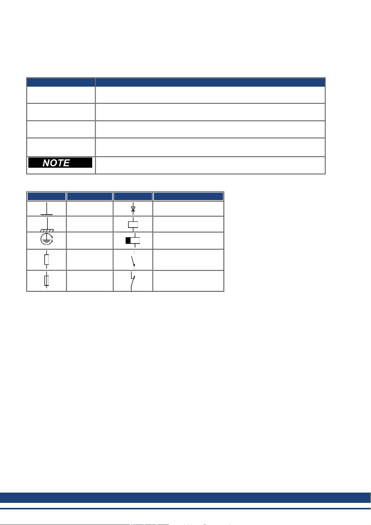
1.5 Symbols used
Warning Symbols
Symbol Indication
Indicates a hazardous situation which, if not avoided, will result in death orserious
injury.
Indicates a hazardous situation which, if not avoided, could result in death or serious
injury.
Indicates a hazardous situation which, if not avoided, could result in minor or moderate injury.
Indicates situations which, if not avoided, could result in property damage.
This is not a safety symbol.
This symbol indicates important notes.
Drawing symbols
Symbol Description Symbol Description
Signal ground Diode
Chassis ground Relays
Protective earth Relays switch off
delayed
Resistor Normal opencontact
Fuse Normal closed contact
12 Kollmorgen™ | March 2012

AKD Installation | 1 General
1.6 Standards Used
Standard Content
ISO 4762 Hexagon socket headcap screws
ISO 11898 Road vehicles — Controller area network (CAN)
ISO 12100 Safety of machinery: Basic concepts, general principles for design
ISO 13849 Safety of machinery: Safety-related parts of control systems
IEC 60085 Electrical insulation - Thermal evaluation and designation Maintenance
IEC 60204 Safety of Machinery: Electrical equipment of machinery
IEC 60364 Low-voltage electrical installations
IEC 60439 Low-Voltage Switchgear andControlgear Assemblies
IEC 60529 International protection rating(IP code)
IEC 60664 Insulation coordination forequipment within low-voltage systems
IEC 60721 Classification of environmental conditions
IEC 61000 Electromagnetic compatibility (EMC)
IEC 61131 Programmablecontrollers
IEC 61491 Electrical equipment of industrial machines – Serial data link for real-time communications
between controls and drives.
IEC 61508 Functional safety of electrical/electronic/programmableelectronic safety-related systems
IEC 61800 Adjustable speed electrical power drive systems
IEC 62061 Functional safety of electrical/electronic/programmableelectronic safety-related systems
IEC 62079 Preparation of instructions - Structuring, content andpresentation
ANSI Z535 Product safety (symbols, colors, information)
UL 840 UL Standardfor Safety for Insulation CoordinationIncluding Clearances and Creepage Distances
for Electrical Equipment
UL 508C UL Standard for Safety Power Conversion Equipment
ANSI - American National Standard Institute, Inc.
IEC - International Electrotechnical Commission
ISO - International Organizationfor Standardization
UL - Underwriters Laboratories
Kollmorgen™ | March 2012 13

AKD Installation | 2 Safety
2 Safety
2.1 Safety Instructions 15
2.2 Use as Directed 16
2.3 Prohibited Use 16
14 Kollmorgen™ | March 2012

2.1 Safety Instructions
During operation, hazards exist that can cause death, severe injury, or material
damage. Do not open or touch the equipment during operation. Keep all covers
and cabinet doors closed during operation. Only properly qualified persons may
handle the equipment during installation and commissioning .
l During operation, drives may have uncovered live components, depending
l Control and power connections may be live, even though the motor is not
l Drives may have hot surfaces during operation. The heat sink can reach tem-
The danger of electrical arcing is present. Electrical arcing can damage contacts
and injure personnel. Never undo any electrical connections to the drive while it is
live.
Wait at least 7 minutes after disconnecting the drive from the main supply power
before touching potentially live sections of the equipment (such as contacts) or
removing any connections.
Capacitors can have dangerous voltages present up to seven minutes after switching off the supply power. Always measure the voltage in the DC bus link and wait
until the voltage is below 40 V before handling components.
AKD Installation | 2 Safety
on their level of enclosure protection.
rotating.
peratures above 80°C.
Incorrect handling of the drive can lead to personnel injury or material damage.
Read this documentation before installing and commissioning the drive. It is vital
that you keep to the technical data and information on connection requirements
(nameplate and documentation).
Only properly qualified personnel may perform activities such as transport, installation, commissioning, and maintenance. Properly qualified persons are those who
are familiar with the transport, assembly, installation, commissioning and operation of the product, and who have the appropriate qualifications for their job. The
qualified personnel must know and observe the following standards:
l IEC 60364 and IEC 60664
l national accident prevention regulations
The manufacturer of the machine must produce a risk assessment for the machine
and take appropriate measures to ensure that unforeseen movements do not result
in personnel injury or material damage.
It is not allowed to modify this device without permission by the manufacturer.
Check the Hardware Revision Number of the product (see product label). This
revision number must match the Hardware Revision Number on the cover page of
the manual.
The drives contain electrostatically sensitive components which may be damaged
by incorrect handling. Electrostatically discharge your body before touching the
drive. Avoid contact with highly insulating materials (artificial fabrics, plastic film
etc.). Place the drive on a conductive surface.
Kollmorgen™ | March 2012 15

AKD Installation | 2 Safety
2.2 Use as Directed
Drives are components that are built into electrical plants or machines and can only be operated as integral components of these plants or machines. The manufacturer of the machine used with a drive must generate a risk
assessment for the machine andtake appropriate measures to ensure that unforeseen movements cannot cause
personnel injury or property damage.
Cabinet and wiring
Drives must only be operated in a closed control cabinet suitablefor the ambient conditions => p. 30. Ventilation
or cooling may be necessary to keep the temperaturewithin the cabinet below 40 °C.
Use only copperconductors for wiring. The conductor cross-sections can be derived from the standard IEC
60204 (alternatively for AWG cross-sections: NEC Table 310-16, 75 °C column).
Power supply
Drives in the AKD series can be supplied as follows:
l AKD-xzzz06: 1 or 3 phase industrial supply networks
(not more than 200 kA symmetrical ratedcurrent at 120 V and 240 V).
l AKD-xzzz07: 3 phase industrial supply networks
(not more than 200 kA symmetrical ratedcurrent at 240 V, 400 V and 480 V).
Connection to other voltage types of supply networks is possible with an additional isolating transformer (=> p.
88).
Periodic overvoltages between phases (L1, L2, L3) and the housing of the drive must not exceed 1000 V peak. In
accordance with IEC 61800, voltage spikes (< 50 µs) between phases must not exceed1000 V. Voltage spikes
(< 50 µs) between a phase and the housingmust not exceed2000 V.
EMC filter measures for AKD-xzzz06 must be implemented by the user.
Motor voltage rating
The AKD family of drives is exclusively intended for driving suitable synchronous servomotors with closed-loop
control of torque, speed, and/or position. The rated voltage of the motors must be at least as high as the DC bus
link voltage divided by √2 produced by the drive (U
nMotor
>=UDC/√2).
Safe torque off
Review the section "Use as Directed" in the STO chapter (=> p. 52) beforeusing this safety function (according
to ISO 13849category 3).
2.3 Prohibited Use
Otheruse than that described in chapter “Use as directed” is not intended and can lead to personnel injuries and
equipment damage. The drive may not be used with a machine that does not comply with appropriate national
directives orstandards. The use of the drive in the following environments is also prohibited:
l potentially explosive areas
l environments with corrosive and/or electrically conductive acids, alkaline solutions, oils, vapors, dusts
l ships or offshore applications
16 Kollmorgen™ | March 2012

AKD Installation | 3 Approvals
3 Approvals
3.1 Conformance with UL/cUL 18
3.2 CE Conformance 20
3.3 Safe Torque Off (STO) 23
Kollmorgen™ | March 2012 17
AKD Installation | 3 Approvals
3.1 Conformance with UL/cUL
This drive is listed underUL (Underwriters Laboratories Inc.) file number E141084 Vol.3 Sec.5.
USL, CNL – Power conversionequipment (NMMS, NMMS7) – Models AKD followedby B,P,S,M or F, followed
by 003, 006, 012, and 024, followed by 06 or 07, followedby additional suffixes.
USL
Indicates Investigated to United States Standard for PowerConversion Equipment, UL 508C, Third Edition,
Revised February 15, 2008.
CNL
Indicates investigation to Canadian Standardfor Industrial Control Equipment, CAN/CSA - C22.2 No. 14-2005,
SecondEdition, Revised April 2008.
Note:
CNL = Canadian National Standards - Listed.
USL = United States Standards - Listed.
3.1.1 UL Markings
l These drives areopen type adjustable frequency motordrives that provide variable speedcontrol to
motors and provides overload protection and current limit control.
l These devices are intended to be usedin a pollution degree 2 environment.
l Identification of the terminals on the controller are coded so they may be identified in the instructions. The
instructions shall identify power connections for power supply, load, control, and ground.
l Integral solid state short circuit protection does not provide branch circuit protection. Branch circuit pro-
tection must be provided in accordance with the National Electrical Code andany additional local codes,
or the equivalent.
l This product is suitable for use ona circuit capableof delivering not more than 200,000 rms symmetrical
amperes, 240 V (AKD-xzzz06) / 480 V (AKD-xzzz07) volts maximum, when protected by ” Fuses", or
equivalant.
l The following fuse types are recommended:
Model Fuse class Rating Max. Fuse Rating
AKD-x00306 J 600Vac, 200 kA 10 A
AKD-x00606 J 600Vac, 200 kA 15 A
AKD-x01206 J 600Vac, 200 kA 15 A
AKD-x02406 J 600Vac, 200 kA 30 A
AKD-x00307 J 600Vac, 200 kA 6A
AKD-x00607 J 600Vac, 200 kA 10 A
AKD-x01207 J 600Vac, 200 kA 15 A
AKD-x02407 J 600Vac, 200 kA 30 A
l These drives provide solid state motor overload protection at 125% of the rated FLA Current.
l Use minimum 75°C copperwire.
18 Kollmorgen™ | March 2012

AKD Installation | 3 Approvals
l The following table illustrates the torque requirements for the field wiring connectors:
Model Mains Connector Motor Phase Connector 24 Vdc Input Connector
AKD-x00306 5-7in-lbs 5-7 in-lbs 4 in-lbs
AKD-x00606 5-7in-lbs 5-7 in-lbs 4 in-lbs
AKD-x01206 5-7in-lbs 7 in-lbs 4 in-lbs
AKD-x02406 7 in-lbs 7 in-lbs 4 in-lbs
AKD-x00307 7 in-lbs 7 in-lbs 4 in-lbs
AKD-x00607 7 in-lbs 7 in-lbs 4 in-lbs
AKD-x01207 7 in-lbs 7 in-lbs 4 in-lbs
AKD-x02407 7 in-lbs 7 in-lbs 4 in-lbs
l Maximum surrounding air temperature of 40°C” or equivalent.
Kollmorgen™ | March 2012 19
AKD Installation | 3 Approvals
3.2 CE Conformance
Conformance with the EC EMC Directive 2004/108/EC and the Low Voltage Directive 2006/95/EC is mandatory
for the supply of drives within the European Community.
The drives have been tested by an authorized testing laboratory in a defined configuration, using the system components that aredescribed in this documentation. Any divergence from the configuration and installation
described in this documentationmeans that the user will be responsible for carrying out new measurements to
ensure conformance with regulatory requirements.
AKD-xzzz06
AKD-xzzz06 drives do not have integrated EMC filters. These drives can cause highfrequency interferences and may require measures for interference suppression
(such as additional external EMC filters).
With external EMC filters for noise emission the drives meet the noise immunity requirements of the second environmental category (industrial environment) to a product of the category C2 (motorcable < 10 m).
With a motor cable length of 10 m or longer and external EMC filters, the drive meets the requirement of category
C3.
AKD-xzzz07
AKD-xzzz07 drives have integrated EMC filters.
The drive meets the noise immunity requirements to the 2nd environmental category (industrial environment). For
noise emission the drive meets the requirement to a product of the Category C2 (motorcable < 10 m).
With a motor cable length of 10 m or longer, the servo drive meets the requirement to the Category C3.
20 Kollmorgen™ | March 2012
AKD Installation | 3 Approvals
3.2.1 European Directives and Standards for the machine builder
Drives are components that are intended to be incorporated into electrical plant and machines for industrial use.
When the drives are built into machines or plant, the drive must not be used until it has been established that the
machine or equipment fulfills the requirements of the
l EC Machinery Directive (2006/42/EC)
l EC EMC Directive (2004/108/EC)
l EC Low Voltage Directive (2006/95/EC)
Standards to be applied for conformance with the EC Machinery Directive (2006/42/EC)
l IEC 60204-1(Safety and Electrical Equipment in Machines)
l ISO 12100 (Safety of Machines)
The manufacturer of the machine must generate a risk assessment for the machine,
and must implement appropriate measures to ensure that unforeseen movements
cannot cause injury or damage to any person or property.
Standards to be applied for conformance with the EC Low Voltage Directive(2006/95/EC)
l IEC 60204-1(Safety and Electrical Equipment in Machines)
l IEC 60439-1(Low-voltage switchgear and controlgearassemblies)
Standards to be applied for conformance with the EC EMC Directive (2004/108/EC)
l IEC 61000-6-1/2 (Interference Immunity in Residential & Industrial Areas)
l IEC 61000-6-3/4 (Interference Generationin Residential & Industrial Areas)
The manufacturerof the machine/plant is responsible for ensuring that it meets the limits required by the EMC
regulations. Advice on the correct installation for EMC (such as shielding, grounding, treatment of connectors
andcable layout) is shown in this manual.
The machine/plant manufacturer must check whether other standards or EC Directives must be applied to the machine/plant.
Kollmorgen™ only guarantees the conformance of the servosystem with the standards cited in this chapter if the
components (motor, cables, chokes etc.) are those supplied by Kollmorgen™.
Kollmorgen™ | March 2012 21

AKD Installation | 3 Approvals
3.2.2 EC Declaration of Conformity
22 Kollmorgen™ | March 2012

AKD Installation | 3 Approvals
3.3 Safe Torque Off (STO)
An additional digital input (STO) releases the power output stage of the drive as long as a 24 V signal is appliedto
this input. If the STO input goes open-circuit, then power will no longerbe supplied to the motor, and the drive will
lose all torque and coast to a stop.
The STO safety implementation on the AKD is certified by the IFA (Institut für Arbeitsschutz der Deutschen
Gesetzlichen Unfallversicherung). The safety circuit implementation for realizingthe safety function "Safe
TorqueOff" in the drive is suited for SIL2 according to IEC 61508-2 and PLd, Cat.3 according to ISO 13849-1.
The subsystems (AKD drives) aretotally described for safety technics with the characteristic data :
Device Operation Mode ISO 13849-1 IEC 61508-2 PFH [1/h] SFF[%]
STO STO single channel PLd, Cat.3 SIL2 0 20
Kollmorgen™ | March 2012 23

AKD Installation | 4 Handling
4 Handling
4.1 Transport 25
4.2 Packaging 25
4.3 Storage 25
4.4 Maintenance and Cleaning 26
4.5 Uninstalling 26
4.6 Repair and Disposal 26
24 Kollmorgen™ | March 2012
AKD Installation | 4 Handling
4.1 Transport
Transport the AKD in accordance with IEC 61800-2as follows:
l Transport only by qualifiedpersonnel in the manufacturer’s original recyclable packaging.
l Avoid shocks while transporting.
l Transport only within specified temperature ranges: -25 to +70 °C, max. rate of change20 K/hour, class
2K3.
l Transport only within specifiedhumidity: max. 95% relative humidity, nocondensation, class 2K3.
The drives contain electrostatically sensitive components that can be damaged by
incorrect handling. Electrostatically discharge yourself before touching the drive.
Avoid contact with highly insulating materials, such as artificial fabrics and plastic
films. Place the drive on a conductive surface.
If the packagingis damaged, check the unit for visible damage. Inform the shipper and the manufacturerof any
damageto the package or product.
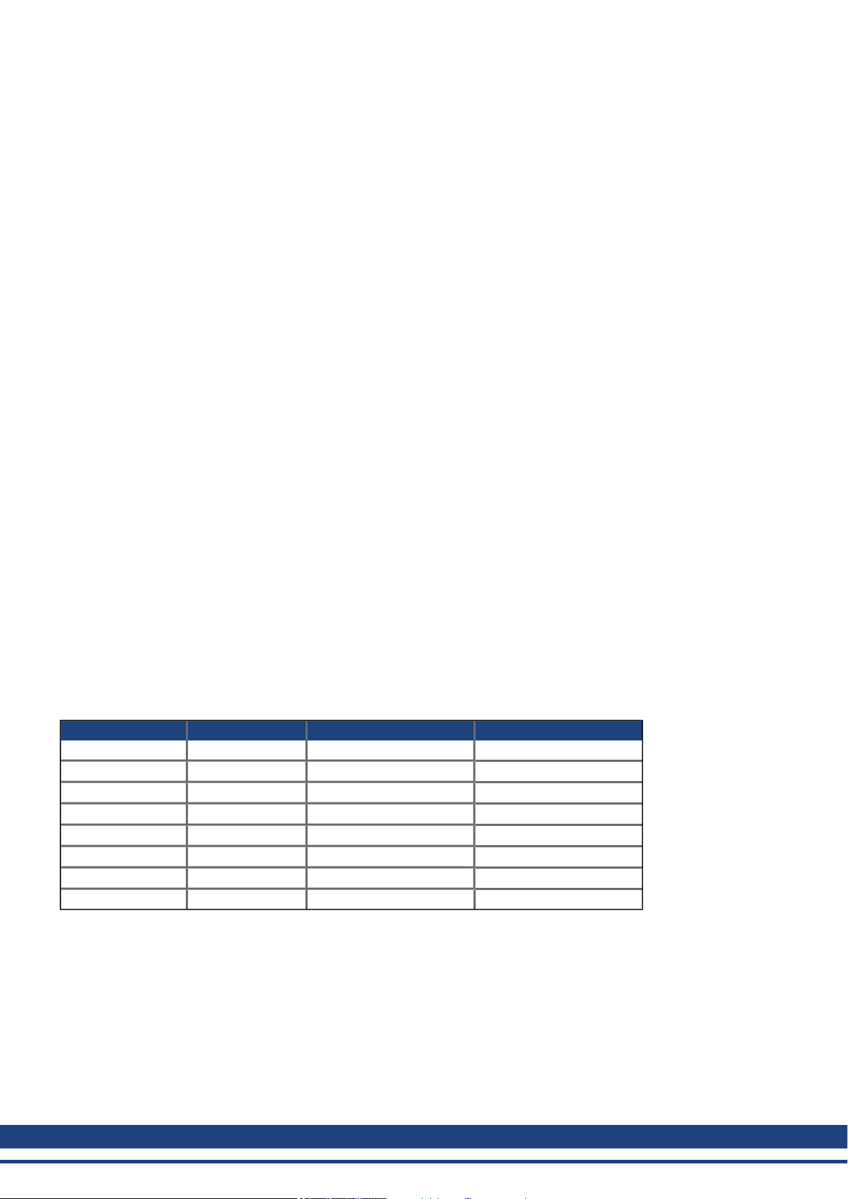
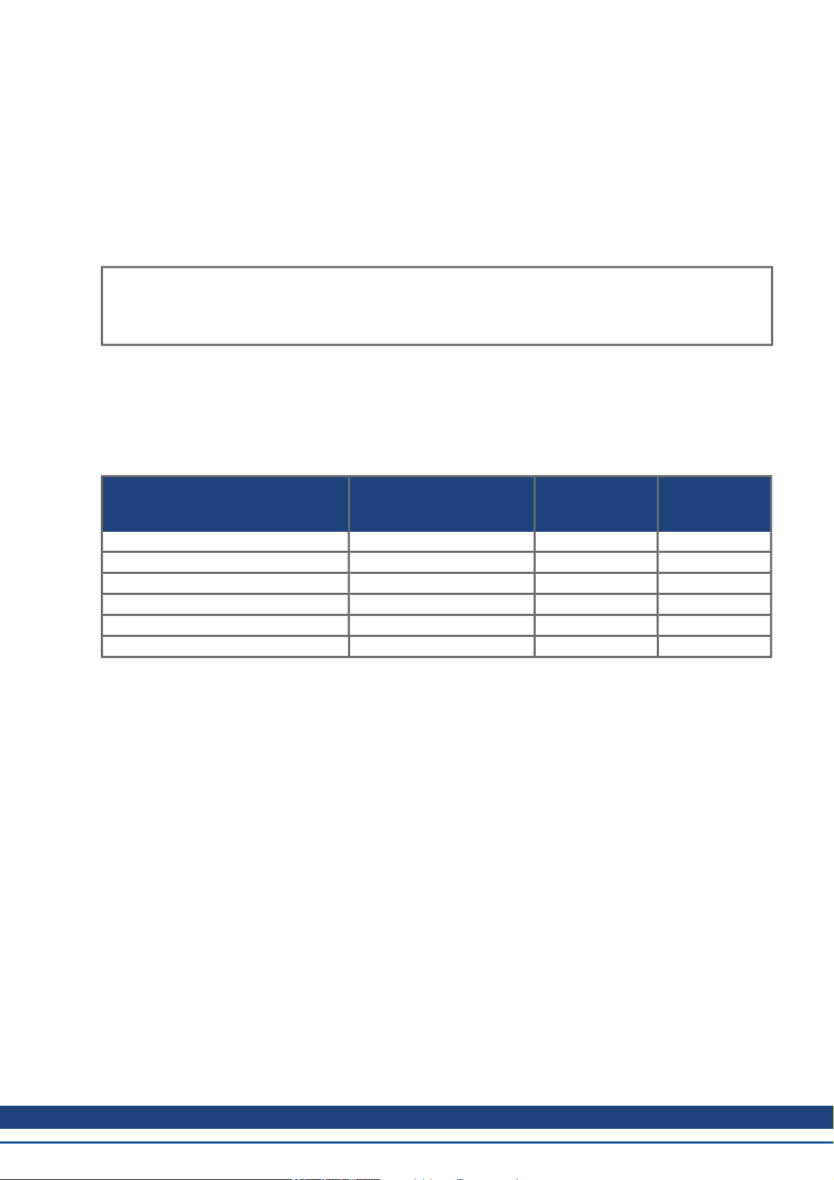
4.2 Packaging
The AKD packagingconsists of recyclablecardboard with inserts and a label on the outside of the box.
Model AKD
Package Dimensions
(mm) HxWxL
Total Weight
AKD-B, -P, -T
(kg)
Total Weight
AKD-M
(kg)
AKD-x00306 and AKD-x00606 113 x 250 x 222 1.7 1.9
AKD-x01206 158x 394 x 292 3.4 3.6
AKD-x02406 158x 394 x 292 5 AKD-x00307 and AKD-x00607 158 x 394 x 292 4.3 4.5
AKD-x01207 158x 394 x 292 4.3 4.5
AKD-x02407 158x 394 x 292 6.7 -
4.3 Storage
Store the AKD in accordance with IEC 61800-2 as follows:
l Store only in the manufacturer’s original recyclablepackaging.
l Store at or below maximum stacking height:
l AKD-x0306to 0606 models: 8 cartons
l All other models: 6 cartons
l Store only within specified temperature ranges: -25 to +55 °C, max.rate of change20 K/hour, class 1K4.
l Storage only within specified humidity: 5 to 95% relative humidity, no condensation, class 1K3.
l Store in accordance with the following durationrequirements:
l Less than1 year: without restriction.
l More than 1 year: capacitors must be re-formed before setting upand operating the drive. To re-form
the capacitors, remove all electrical connections and apply single-phase 120 Vac for about 30 minutes
to the L1/L2terminals.
Kollmorgen™ | March 2012 25
AKD Installation | 4 Handling
4.4 Maintenance and Cleaning
The drive does not requiremaintenance. Opening the drive voids the warranty.
The inside of the unit can only be cleanedby the manufacturer. To cleanthe drive exterior:
l Casing: Clean with isopropanol or similar cleaning solution.
l Protective grill onfan: Clean with a dry brush.
Do not immerse or spray the drive.
4.5 Uninstalling
If a drive must be uninstalled (such as for replacement), remove the drive as follows:
1. Switch off the main switch of the switchgearcabinet and the fuses that supply the system.
Wait at least seven minutes after disconnecting the drive from the main supply
power before touching potentially live sections of the equipment (e.g. contacts) or
undoing any connections. Always measure the voltage in the DC bus link and wait
until the voltage is below 40 V before touching or handling the drive.
2. Remove the connectors. Disconnect the potential earth connection last.
3. Check temperature.
During operation, the heat sink of the drive may reach temperatures above 80°C
(176°F). Before touching the device, check the temperature and wait until it has
cooled below 40°C (104°F).
4. Uninstall. Remove the drive and power supply from the conductive, grounded mountingplate in the cabinet.
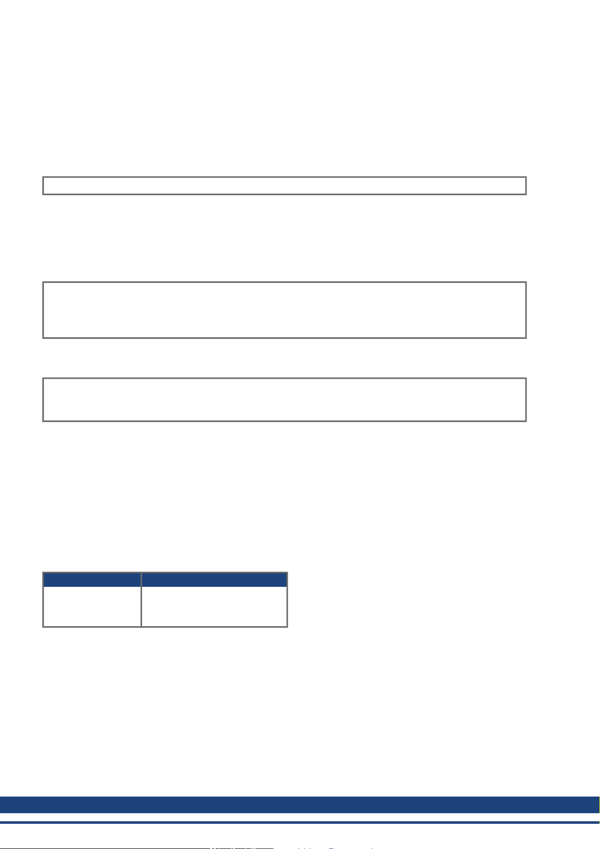
4.6 Repair and Disposal
Only the manufacturer can repair the drive. Opening the device voids the warranty. Uninstall the drive as
described in "Uninstalling" (=> p. 26)and send it in the original packaging to the manufacturer (see table below).
In accordance with the WEEE-2002/96/EC-Guidelines andsimilar, the manufacturer accepts returns of old
devices and accessories for professional disposal. Transport costs are the responsibility of the sender. Send the
devices to the manufactureraddresses shown in the table below.
USA Europe
Kollmorgen™
201West Rock Road
Radford, VA 24141
KOLLMORGEN Europe GmbH
Pempelfurtstr. 1
D-40880Ratingen
26 Kollmorgen™ | March 2012

AKD Installation | 5 Package
5 Package
5.1 Package Supplied 28
5.2 Nameplate 28
5.3 Part number scheme 29
Kollmorgen™ | March 2012 27
AKD Installation | 5 Package
5.1 Package Supplied
When a drive from the AKD series is ordered, the following items are included in the drive package:
l AKD
l Printed copy of AKD Installation Manual (EU only)
l Printed copy of AKD Quick Start (not in EU)
l Printed copy of fault and warning card(not in EU)
l CD-ROM containingthe setup software, WorkBench, and all product documentation in digital format.
l Mating connectors X1, X2, X3, X4 (if required), X7 and X8, X35 andX36 (if required)
l Grounding plate, with AKD voltage type 07, with voltage type 06 for EU only
The mating SubD and RJ45 connectors are not included in the package.
Accessories Sold Separately
Accessories must beorderedseparately if required; refer to your regional accessories manual:
l EMC filters for 24 V and mains supply voltage, categories C2 or C3
l External regen resistor
l Motorcable. Assembled motor cables are available for all regions.
l Feedback cable. Assembled feedback cables are available forall regions.
l Motorchoke, for motorcables longer than 25 m
l CAN terminationconnector (with CAN drives only)
l Service cable to the network
l Power cable, control cables, and fieldbus cables (as cutoff lengths)
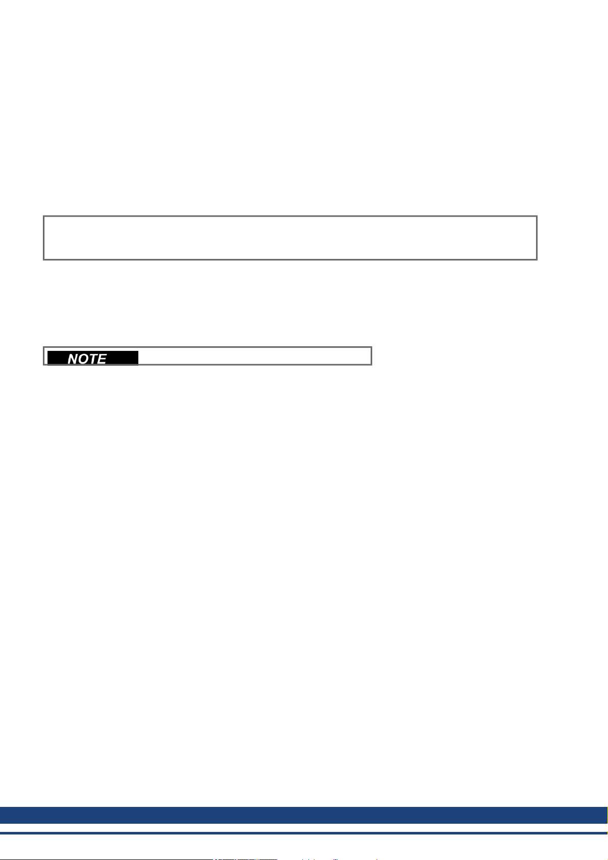
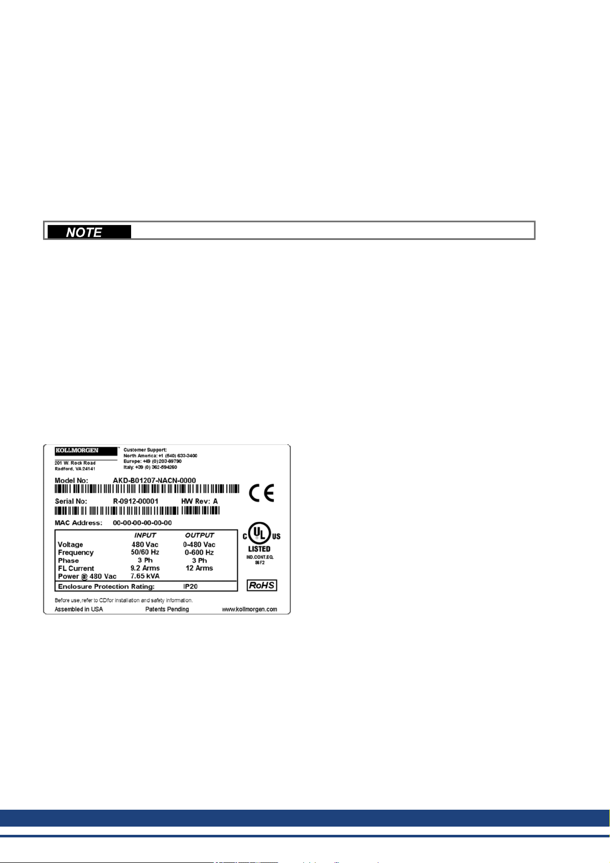
5.2 Nameplate
The nameplate depicted below is attached to the side of the drive, sample data entries are for a 12A type.
28 Kollmorgen™ | March 2012
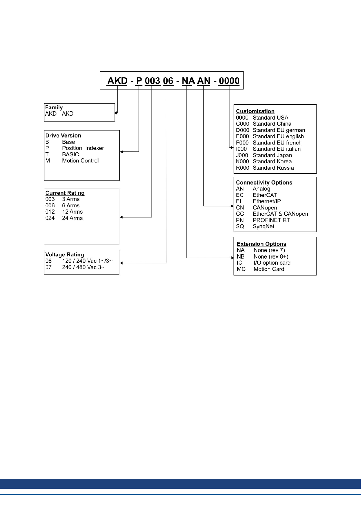
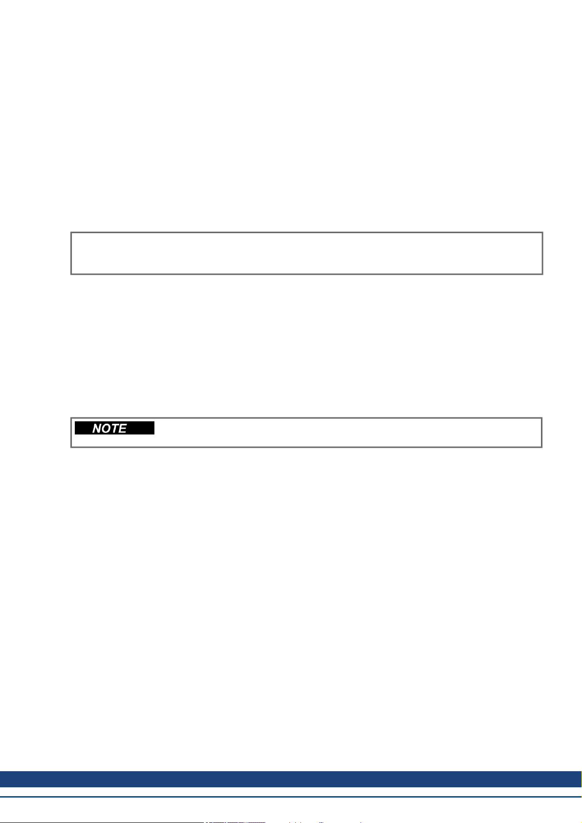
5.3 Part number scheme
The part number is identical to the order code.
AKD Installation | 5 Package
Version: "T" (BASIC version)is not available in Europe
Customization: this code includes language version of printedmaterial and customer specials.
Connectivity Options: The drive models with connectivity optionCC are fitted with both the EtherCAT ( X5 and
X6) and CANopen (X12 and X13) fieldbus connectors. A software parameter (DRV.TYPE) allows you to select
what features the drive supports; you cannot use EtherCAT and CANopen at the same time. PROFINET is possible with Position Indexer drives only (P version).
Kollmorgen™ | March 2012 29

AKD Installation | 6 Technical descriptionand data
6 Technical description and data
6.1 The AKD Family of Digital Drives 31
6.2 Ambient Conditions, Ventilation, and Mounting Position 33
6.3 Mechanical Data 33
6.4 Inputs/Outputs 33
6.5 Electrical Data AKD-xzzz06 34
6.6 Electrical Data AKD-xzzz07 35
6.7 Performance Data 36
6.8 Recommended tightening torques 36
6.9 Fusing 37
6.10 Grounding System 37
6.11 Connectors 38
6.12 Cable and Wire Requirements 39
6.13 Dynamic Braking 40
6.14 Switch-on and Switch-off Behavior 43
6.15 Stop / Emergency Stop / Emergency Off 50
6.16 Safe Torque Off (STO) 52
6.17 Shock-hazard Protection 57
30 Kollmorgen™ | March 2012
 Loading...