

Page 1
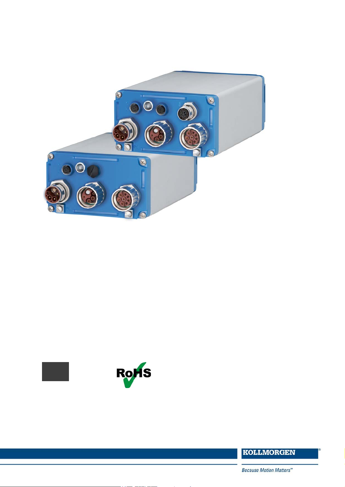
AKD
®
Near Servo Drive
Installation Manual
Edition: C, December 2014
Valid for AKD-N, Hardware Revision B
Part Number 903-200018-00
Original Document
Keep all manuals as a product component duringthelife span of the product.
Pass all manuals to future users and owners of the product.
Page 2
Record of document revisions
Revision Remarks
A, 11/2013 First edition
B, 05/2014 STO section updated
C, 12/2014 Patents updated, typos corrected, HR changed acc. to export control
Hardware Revision (HR)
AKD-N AKD-C
Firmware/
WorkBench
Export
Classification
Remarks
A A from 1.11 3A225 AKD-C and AKD-N start revisions
B A from 1.13 -
AKD-N Hardware Revision for export classification
tracebility purposes
Trademarks
l AKD is a registered trademark of Kollmorgen Corporation
l EnDat is a registeredtrademark of Dr. Johannes Heidenhain GmbH
l EtherCAT is a registered trademark and patented technology, licensed by Beckhoff AutomationGmbH
l HIPERFACE is a registered trademark of Max Stegmann GmbH
l Windows is a registeredtrademark of Microsoft Corporation
Current patents
l US Patent 5.162.798 (used in control card R/D)
l US Patent 5.646.496 (used in control card R/D and1 Vp-p feedback interface)
l US Patent 6.118.241 (used in control card simple dynamic braking)
l US Patent 8.154.228 (Dynamic Braking For Electric Motors)
l US Patent 8.214.063 (Auto-tune of a Control System Based on Frequency Response)
l US Patent 8.566.415 (Safe Torque Off over network wiring)
Patents referring to fieldbus functions are listed in the matching fieldbus manual.
Technical changes which improve the performance of the device may be made without prior notice!
Printedin Germany
This document is the intellectual property of Kollmorgen. All rights reserved. No part of this work may be reproduced in any form (by photocopying, microfilm or any other method) or stored, processed, copied or distributed
by electronic means without the written permission of Kollmorgen.
2 Kollmorgen | December 2014
Page 3

AKD-N Installation | Table of Contents
1 Table of Contents
1 Table of Contents 3
2 General 7
2.1 About this Manual 8
2.2 Using the PDF Format 8
2.3 Notes for the Printed Edition (paper version) 8
2.4 Symbols Used 9
2.5 Abbreviations Used 9
3 Safety 10
3.1 You should pay attention to this 11
3.2 Use as Directed 13
3.3 Prohibited Use 13
3.4 Handling 14
3.4.1 Packaging 14
3.4.2 Transport 14
3.4.3 Storage 14
3.4.4 Maintenance and cleaning 14
3.4.5 Uninstalling 15
3.4.6 Repair and disposal 15
4 Approvals 16
4.1 Conformance with UL/cUL 17
4.2 Conformance with EC Low Voltage and EMC Directives 17
4.3 Conformance with EC Machinery Directive, Functional Safety 17
5 Package 18
5.1 Package Supplied 19
5.2 Nameplate 19
5.3 Part Number Scheme 20
6 Technical description and data 21
6.1 The AKD-N Family of Digital Drives 22
6.2 Mechanical Data 23
6.3 Electrical Data 23
6.4 Performance Data 23
6.5 Ambient Conditions, Ventilation, and Mounting Position 24
6.6 Inputs/Outputs 24
6.7 Connectors 25
6.8 Cable Requirements 25
6.9 Cable length definition 26
6.10 Dynamic Braking 27
6.11 Regen circuit 27
6.11.1 Functional description 27
6.11.2 Technical data 27
6.12 LED Codes 28
6.13 Switch-On and Switch-Off Behavior 29
Kollmorgen | December 2014 3
Page 4

AKD-N Installation | Table of Contents
6.13.1 Switch-onbehaviorin standard operation 29
6.13.2 Switch-off behavior 30
6.13.2.1 Switch-off behaviorusing a digital input (controlled stop) 30
6.13.2.2 Switch-off behaviorusing the DRV.DIS command 31
6.13.2.3 Switch-off behaviorusing HW Enable input on AKD-C (uncontrolled stop) 32
6.13.2.4 Switch-off behaviorin the event of a fault 33
6.14 Safe Torque Off (STO) 36
6.14.1 Global STO, control via AKD-C 36
6.14.2 Local STO, control via digital input on AKD-N-DS 36
6.14.3 Safety characteristic data 36
6.14.4 Response Time 37
6.14.5 Use as directed 37
6.14.6 Prohibited use 37
6.14.7 Enclosure, wiring 37
6.14.8 Local STO safety instructions 38
6.14.9 Technical data and pinout local STO 39
6.14.10 Functional description local STO 40
6.14.10.1 Signal diagram (sequence) 40
6.14.11 Functional test 41
6.14.11.1 Global STO 41
6.14.11.2 Local STO 41
6.14.11.3 Local STO application example 42
7 Mechanical Installation 43
7.1 Important Notes 44
7.2 Temperature Management 44
7.3 Mechanical Drawings 45
7.3.1 Dimensions AKD-N, preferred mounting 45
7.3.2 Dimensions AKD-N with optional heat sink, preferred mounting 46
8 Electrical Installation 47
8.1 Important Notes 48
8.2 Guide to Electrical Installation 48
8.3 System Topology of a Decentralized Servo System 49
8.3.1 System limits 49
8.3.2 Example 49
8.4 Wiring 50
8.5 Connection Overview 51
8.5.1 Connector assignment AKD-Nzzz07-DB 51
8.5.2 Connector assignment AKD-Nzzz07-DF/DS 51
8.5.3 Connection diagram AKD-Nzzz07-DB 52
8.5.4 Connection diagram AKD-Nzzz07-DF/DS 53
8.6 Hybrid Connection (X1, X2) 54
8.7 I/O Connection (X3) 54
8.7.1 Digital Inputs 55
8.7.2 Digital Output 56
8.8 Motor Power Connection (X4) 57
8.8.1 Connector X4 AKD-Nzzz07-DB/DS/DF, hybrid, single line 57
4 Kollmorgen | December 2014
Page 5

AKD-N Installation | Table of Contents
8.8.2 Connector X4 AKD-Nzzz07-DF/DS, dual line 57
8.9 Motor Brake Connection (X4) 58
8.10 Motor Feedback Connection (X4, X5) 59
8.10.1 Connector X4 AKD-Nzzz07-DB/DS/DF, hybrid, single line 59
8.10.2 Connector X5 AKD-Nzzz07-DF/DS, dual line 60
8.11 Optional Connector (X6) 61
8.11.1 Pinout AKD-Nzzz07-DF 61
8.11.2 Pinout AKD-Nzzz07-DS 61
9 Setup 62
9.1 Important Notes 63
9.2 Setup software WorkBench 64
9.3 Initial System Test 65
9.3.1 Unpacking, mounting, and wiring 65
9.3.2 Set IP address 65
9.3.3 Confirm connections 65
9.3.4 Install and start WorkBench 66
9.3.5 Enable the drive using the setup wizard 66
9.4 Fault and Warning Messages 66
10 Index 67
Kollmorgen | December 2014 5
Page 6

AKD-N Installation | Table of Contents
This page intentionally left blank.
6 Kollmorgen | December 2014
Page 7

AKD-N Installation | 2 General
2 General
2.1 About this Manual 8
2.2 Using the PDF Format 8
2.3 Notes for the Printed Edition (paper version) 8
2.4 Symbols Used 9
2.5 Abbreviations Used 9
Kollmorgen | December 2014 7
Page 8
AKD-N Installation | 2 General
2.1 About this Manual
This manual, AKD-N Installation Manual ("Instructions Manual" according to EC Machinery
Directive 2006/42/EC), describes the AKD-N series of digital drives and includes information
needed to safely install an AKD-N. A digital version of this manual (pdf format) is availableon
the DVD included with your drive. Manual updates can be downloadedfrom the Kollmorgen
website (www.kollmorgen.com).
Additional documents include the following:
l Decentralized System Projecting Guide: describes how to build a decentralized drive sys-
tem with AKD-C and AKD-N. It provides tips for system topology, cooling, and maximizing the system performance. This document is expected to be published in April
2015.
l AKD-C Installation Manual: describes the AKD-C series of intelligent power supply for
Kollmorgen decentralized drive system and includes information needed for safe assembling, installation andsystem setup.
l Decentralized System User Guide: describes how to use yourdrive in common applic-
ations. It also provides tips for maximizing your system performance. The User Guide
includes the Parameter and Command Reference Guide which provides documentation
for the parameters and commands used to program the AKD-N.
l EtherCAT Communication: describes how to use your system in EtherCAT applications.
l Accessories Manual.It provides documentation for accessories like cables andregen res-
istors used with AKD-C and AKD-N. Regional variants of this manual exist.
2.2 Using the PDF Format
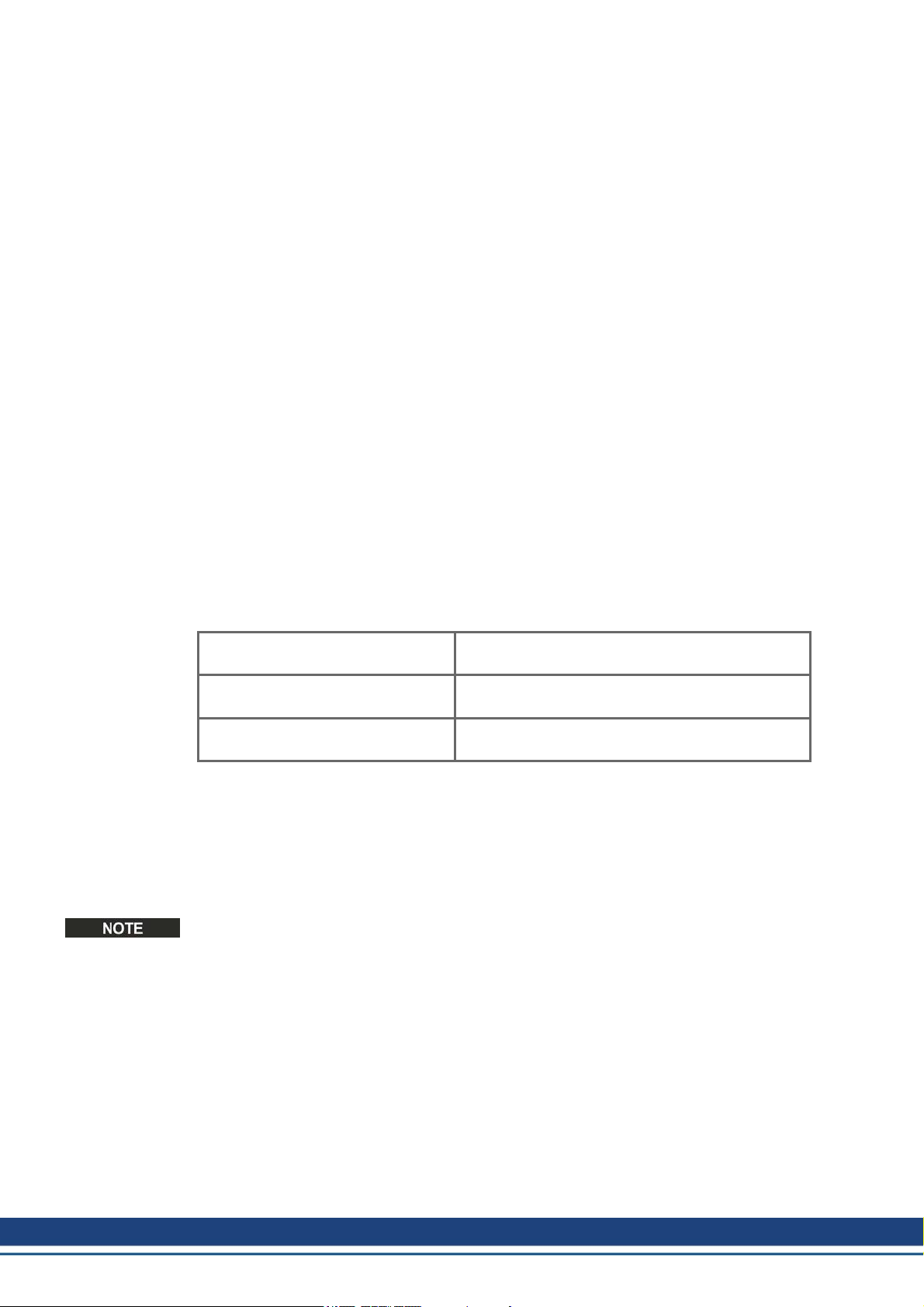
This document includes several features for ease of navigation
Cross References Table of contents and index includeactive cross ref-
erences.
Table of contents and index Lines are active cross references. Click on the line
andthe appropriate pageis accessed.
Page/chapter numbers in the text Page/chapter numbers with cross references are act-
ive links.
2.3 Notes for the Printed Edition (paper version)
A printed version of the manual is enclosed with each product. For
environmental reasons, the document was reduced in size and printed on DIN A5.
Should you experience difficulties reading the font size of the
scaled-down printed version, you can print and use the PDF version in DIN A4 format 1:1. You can find the PDF version on the
DVD accompanying the product and on the Kollmorgen website.
8 Kollmorgen | December 2014
Page 9
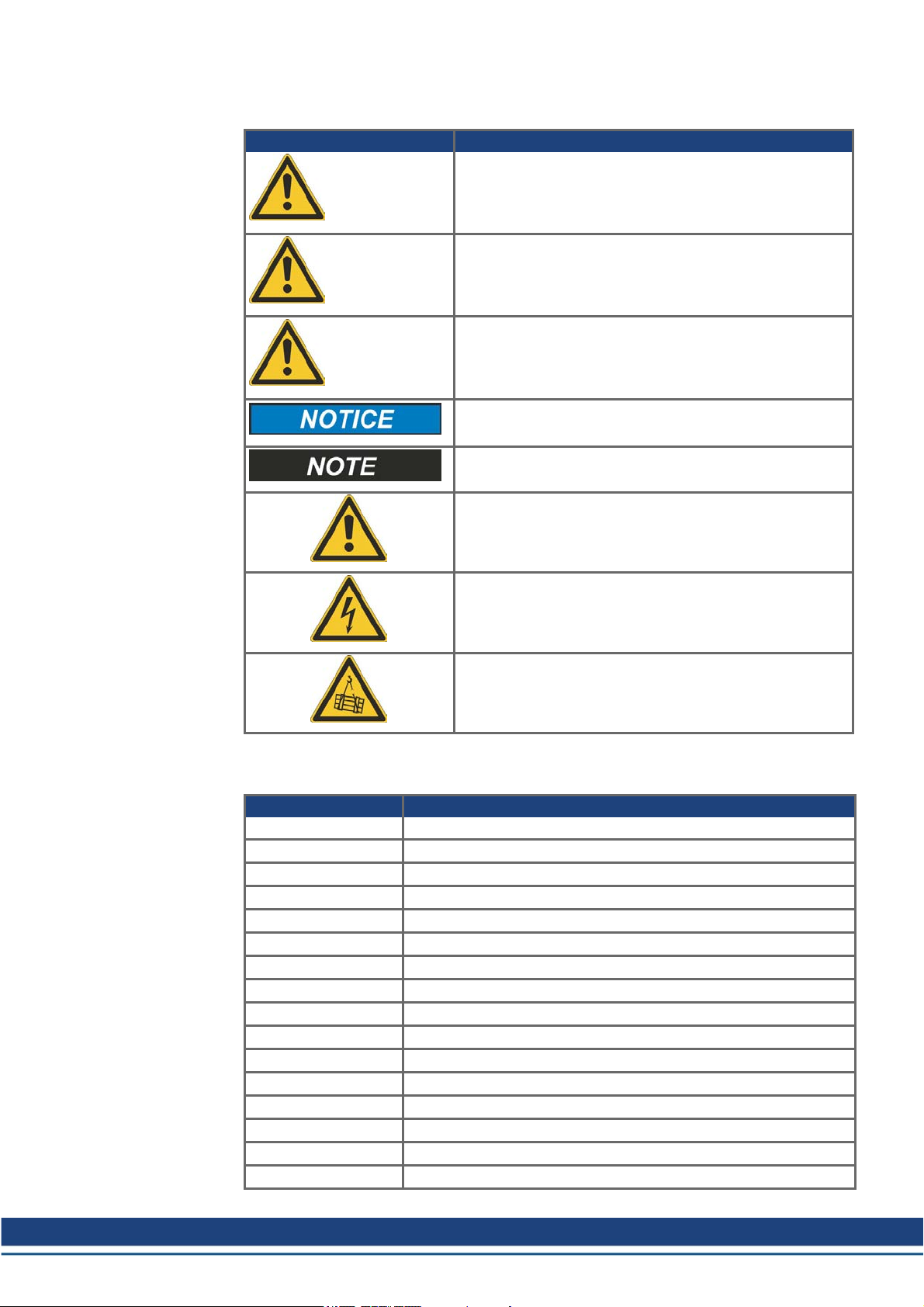
2.4 Symbols Used
Symbol Indication
AKD-N Installation | 2 General
Indicates a hazardous situation which, if not avoided, will
result in death or serious injury.
DANGER
Indicates a hazardous situation which, if not avoided, could
result in death or serious injury.
WARNING
Indicates a hazardous situation which, if not avoided, could
result in minor or moderate injury.
CAUTION
Indicates situations which, if not avoided, could result in
property damage.
This symbol indicates important notes.
2.5 Abbreviations Used
Abbreviation Meaning
CE Communité Européenne
EMC Electromagnetic compatibility
LED Light-emitting diode
OSSD Output signals Switching Device
PC Personal computer
PE Protective earth
PELV Protective extra low voltage
PLC Programmable logic control
PWM Pulse-width modulation
RAM Random access memory (volatile memory)
ROD Incremental encoder (A quad B)
Rth Specific thermal resistance
SELV Safety Extra Low Voltage
STO Safe torque off
VAC Volts, alternatingcurrent
VDC Volts, direct current
Warning of a danger (general). The type of danger is specified by the text next to the symbol.
Warning of danger from electricity and its effects.
Warning of suspendedloads.
Kollmorgen | December 2014 9
Page 10

AKD-N Installation | 3 Safety
3 Safety
3.1 You should pay attention to this 11
3.2 Use as Directed 13
3.3 Prohibited Use 13
3.4 Handling 14
10 Kollmorgen | December 2014
Page 11
3.1 You should pay attention to this
This section helps you to recognize and avoid dangers to peopleand objects.
Read the documentation!
Read the availabledocumentation before installation and commissioning. Improper handling
of the drive can cause harm to people or damage to property. The operator of systems using
the AKD-N must requirethat all personnel who work with the drive read and understand the
manual beforeusing the drive.
Check Hardware Revision!
Check the Hardware Revision Number of the product (see product label). This number is the
link between your product and the manual. The product Hardware Revision Number must
match the Hardware Revision Number on the coverpage of the manual.
Pay attention to the technical data!
Adhere to the technical data and the specifications on connection conditions (rating plate and
documentation). If permissible voltagevalues or current values are exceeded, the drives can
be damaged.
Perform a risk assessment!
The manufacturerof the machine must generate a risk assessment for the machine, and
take appropriate measures to ensure that unforeseen movements cannot cause injury or damageto any person orproperty. Additional requirements on specialist staff may also result
from the risk assessment.
Automatic Restart!
The drive might restart automatically after power on, voltage dip orinterruption of the supply
voltage, depending on theparameter setting.
Risk of death or serious injury for humans working in the machine.
If the parameter DRV.ENDEFAULT is set to 1, then place a warning sign to the machine
(Warning: Automatic Restart at Power On) and ensure, that power onis not possible, while
humans are in a dangerous zone of the machine. In case of using an undervoltage protection
device, you must observe EN 60204-1:2006 chapter 7.5 .
Specialist staff required!
Only properly qualified personnel are permitted to perform such tasks as transport,
assembly, setup and maintenance. Qualified specialist staff arepersons who are familiar
with the transport, installation, assembly, commissioning andoperation of drives and who
bring theirrelevant minimum qualifications to bear on their duties:
l Transport: only by personnel with knowledge of handling electrostatically sensitive com-
ponents.
l Unpacking: only by electrically qualified personnel.
l Installation: only by electrically qualified personnel.
l Basic tests / Setup: only by qualified personnel with knowledge of electrical engineering
anddrive technology
AKD-N Installation | 3 Safety
The qualifiedpersonnel must know and observe ISO 12100/ IEC 60364 / IEC 60664 and
national accident prevention regulations.
Observe electrostatically sensitive components!
The drives contain electrostatically sensitive components which may be damagedby incorrect handling. Electrostatically discharge yourbody before touching the drive. Avoid contact
with highly insulating materials (artificial fabrics, plastic film etc.). Place the drive on a conductive surface.
Kollmorgen | December 2014 11
Page 12
AKD-N Installation | 3 Safety
Hot surface!
Drives may have hot surfaces during operation. The housing can reach temperatures above
80°C. Risk of minor burns! Measure the temperature, andwait until the housinghas cooled
down below 40 °C before touching it.
Earthing!
It is vital that you ensurethat the drive is safely earthed to the PE (protective earth) system
in the maschine. Risk of electric shock. Without low-resistance earthing no personal protection can be guaranteed.
Leakage Current!
Since the leakage current to PE is morethan 3.5 mA, in compliance with IEC61800-5-1 the
PE connection must either be doubled or a connecting cable with a cross-section >10 mm²
must be used. Deviating measures accordingto regional standards might be possible.
High voltages!
The equipment produces highelectric voltages up to 900 V. Do not open or touch the equipment during operation. Keep all covers closed. The built-in LED does not safely indicate the
real voltage level.
Duringoperation, drives may have uncovered live sections, accordingto their level of enclosureprotection. Wait at least seven minutes after disconnecting the drive from the main supply power before touching potentially live sections of the equipment (such as contacts) or
removing any connections.
Capacitors can have dangerous voltages present up to seven minutes after switching off the
supply power. Always measure the voltagein the DC bus link at connector X14 at AKD-C
andwait until the voltage is below 60 V before handling components.
Never undo any electrical connections to the drive while it is live. There is a danger of electrical arcing with damage to contacts and personal injury.
Reinforced Insulation
Thermal sensors, motor holdingbrakes and feedback systems built into the connected motor
must have reinforcedinsulation (according to IEC61800-5-1) against system components
with power voltage, accordingto the required application test voltage. All Kollmorgen components meet these requirements.
Never modify the drive!
It is not allowed to modify the drive without permission by the manufacturer. Openingthe
housing causes loss of warranty.
12 Kollmorgen | December 2014
Page 13

3.2 Use as Directed
The AKD-N family of drives is exclusively intended for driving suitable synchronous servomotors with closed-loop control of torque, speed, and/or position.
Drives are components that are built into electrical plants or machines and can only be operated as integral components of these plants or machines. The manufacturer of the machine
must generate a risk assessment for the machine.
When the drives are built into machines or plant, the drive must not be used until it has been
established that the machine or plant fulfills the requirements of the regional directives.
Kollmorgen Decentralized Drive System
AKD-N series drives must only be operatedin a motion system with components from Kollmorgen. Required additional Kollmorgen components are the intelligent power supply AKDC, CCx series of hybrid cables, motor power and feedback cables, servomotors.
Assembling
AKD-N drives must only be operated in environments suitable for the ambient conditions
defined on➜ p. 24. Optional finned heat sink may be necessary to keep the drive flange temperature below 85 °C.
Wiring
Use only Kollmorgen CCx series of hybrid cables for connecting AKD-N and AKD-C
devices.
Power supply
AKD-N series drives must be powered by AKD-C intelligent powersupplies with DC voltage
from 55 VDC up to 800 VDC.
Motor voltage rating
The rated voltage of the motors must be at least as high as the DC bus link voltage divided
by √2 produced by the drive (U
Safe torque off
Review the section "Use as Directed" in the STO chapter(➜ p. 36) before using this safety
function (SIL2, PLd, category 3 according to ISO 13849).
The 24 VDC supply unit for local STO supply must accord to PELV/SELV (EN 60204-1)
requirements.
nMotor
AKD-N Installation | 3 Safety
>=UDC/√2).
3.3 Prohibited Use
Otheruse thanthat described in chapter “Use as directed” is not intended and can lead to personnel injuries and equipment damage.
The device may not be used
l with a machine that does not comply with appropriate national directives or standards,
l for driving elevators,
l in applications with continuous, operational short circuits to the motor power contacts.
The use of the device in the following environments is also prohibited:
l potentially explosive areas
l environments with corrosive and/or electrically conductive acids, alkaline solutions, oils,
vapors, dusts
l ships or offshoreapplications
Wiring the system with hybrid cables from other manufacturers than Kollmorgen is not
allowed. Changing Kollmorgen cables or connectors is not allowed.
Kollmorgen | December 2014 13
Page 14

AKD-N Installation | 3 Safety
3.4 Handling
3.4.1 Packaging
The AKD-N packaging consists of recyclable cardboardwith inserts and a label on the outside of the box.
3.4.2 Transport
Model Package Dimensions
(mm) HxWxL
Total Weight
(kg)
AKD-N00307 120x 295 x 370 3.2
AKD-N00607 120x 295 x 370 3.2
Transport the AKD-N in accordance with IEC 61800-2 as follows:
l Transport only by qualified personnel in the manufacturer’s original recyclable packaging.
l Avoid shocks while transporting.
l Store at or below maximum stacking height of 8 cartons
l Transport only within specified temperature ranges: -25 to +70 °C, max. rate of change 20
K/hour, class 2K3.
l Transport only within specified humidity: maximum 95% relative humidity, no con-
densation, class 2K3.
The drives contain electrostatically sensitive components that can be damaged by incorrect
handling. Electrostatically discharge yourself before touching the drive. Avoid contact with
highly insulating materials, such as artificial fabrics and plastic films. Place the drive on a
conductive surface.
If the packaging is damaged, check the unit for visible damage. Inform the shipper and the
manufacturer of any damageto the package or product.
3.4.3 Storage
Store the AKD-N in accordance with IEC 61800-2as follows:
l Store only in the manufacturer’s original recyclable packaging.
l Store at or below maximum stacking height of 8 cartons
l Store only within specified temperatureranges: -25 to +55 °C, max.rate of change20
K/hour, class 1K4.
l Storage only within specified humidity: 5 to 95% relative humidity, no condensation, class
1K3.
3.4.4 Maintenance and cleaning
The drive does not requiremaintenance. Opening the drive voids the warranty.
The inside of the unit can only be cleanedby the manufacturer. To clean the drive exterior:
l Casing: Clean with isopropanol or similar cleaning solution.
l Coolingfins: Clean with a dry brush.
14 Kollmorgen | December 2014
Page 15
3.4.5 Uninstalling
AKD-N Installation | 3 Safety
If a drive must be uninstalled (such as for replacement), remove the drive as follows:
1. Switch off the main switch of the switchgear cabinet and the fuses that supply the system.
WARNING
Contacts can still have dangerous voltage present up to seven minutes
after switching off mains voltage. Risk of electrical shock! Wait at least
seven minutes after disconnecting the drive from the main supply power
before touching potentially live sections of the equipment (e.g. contacts)
or undoing any connections. Always measure the voltage in the DC bus
link at connector X14 at AKD-C and wait until the voltage is below 60 V
before handling components.
2. Remove the connectors. Disconnect the potential earth connection last.
3. Check temperature.
CAUTION
During operation, the heat sink of the drive may reach temperatures
above 80°C (176°F). Risk of minor burns. Before touching the device,
check the temperature and wait until it has cooled below 40°C (104°F).
4. Uninstall. Remove the AKD-N.
3.4.6 Repair and disposal
Only the manufacturer can repair the drive. Opening the device voids the warranty. Uninstall
the drive as described in "Uninstalling" (➜ p. 15), then send thedrive in the original packaging to the manufacturer (seetable below). Transport costs are the responsibility of the
senders.
In accordance with the WEEE-2002/96/EC-Guidelines and similar, the manufacturer
accepts returns of old devices and accessories for professional disposal. Transport costs
arethe responsibility of the sender. Sendthe devices to the manufacturer addresses shown
in the table below.
USA Europe
Kollmorgen
201West Rock Road
Radford, VA 24141
KOLLMORGEN Europe GmbH
Pempelfurtstr. 1
D-40880Ratingen
Kollmorgen | December 2014 15
Page 16

AKD-N Installation | 4 Approvals
4 Approvals
4.1 Conformance with UL/cUL 17
4.2 Conformance with EC Low Voltage and EMC Directives 17
4.3 Conformance with EC Machinery Directive, Functional Safety 17
16 Kollmorgen | December 2014
Page 17

4.1 Conformance with UL/cUL
Planned.
4.2 Conformance with EC Low Voltage and EMC Directives
CE Declarations of Conformity can be found on the Kollmorgenwebsite.
Conformance with the EC EMC Directive 2004/108/EC and the Low Voltage Directive
2006/95/EC is mandatory for the supply of drives within the European Community.
The drives have been tested by an authorized testing laboratory in a defined configuration,
using the system components that are describedin this documentation. Any divergence from
the configuration and installation described in this documentation means that the user will be
responsiblefor carrying out new measurements to ensure conformance with regulatory
requirements.
Kollmorgen declares the conformity of the product series AKD-Nzzz07 with the following directives:
l EC Directive 2006/95/EC, low voltage
Used harmonized standard EN61800-5-1 (2007)
l EC Directive 2004/108/EC, electromagnetic compatibility
Used harmonized standard EN 61800-3 (2004)
AKD-N Installation | 4 Approvals
The AKD-Nzzz07 meet the noise immunity requirements to the 2nd environmental category
(industrial environment). For noise emission theAKD-Nzzz07 meet the requirement to a
product of the Category C2 (motor cable up to 5 m).
These devices can cause high-frequency interferences in non industrial environments and
may require measures for interference suppression (such as additional external EMC filters).
4.3 Conformance with EC Machinery Directive, Functional Safety
Conformance with the EC Machinery Directive 2006/42/EC is mandatory for the supply of
safety components within the European Community.
Safe Torque Off (STO) string type
Certification in process.
Safe Torque Off (STO) single drive type
Certification in process.
Kollmorgen | December 2014 17
Page 18

AKD-N Installation | 5 Package
5 Package
5.1 Package Supplied 19
5.2 Nameplate 19
5.3 Part Number Scheme 20
18 Kollmorgen | December 2014
Page 19
5.1 Package Supplied
When a drive from the AKD-N series is ordered, the following items are included in the drive
package:
l AKD-N
l Printedcopy of AKD-N Installation Manual
l DVD containing the setup software, WorkBench, and all product documentation in digital
format.
l Two connector covers M12 (forunused X3 and X6)
The mating connectors arenot included in the package.
The M23 connector cover for protecting X2 of the last AKD-N in a string is part of delivery of
the AKD-C package.
Accessories Sold Separately
Accessories must be ordered separately if required; refer to your regional accessories
manual:
l Heatsink 40 mm or 50 mm
l Heat conducting film
l Motor cable, feedback cable
l Hybrid cable for connection to next AKD-N
l Cable for digital I/O connection
l Cable for local STO connection (AKD-N-DS only)
l Cable for tertiary fieldbus (AKD-N-DF only)
AKD-N Installation | 5 Package
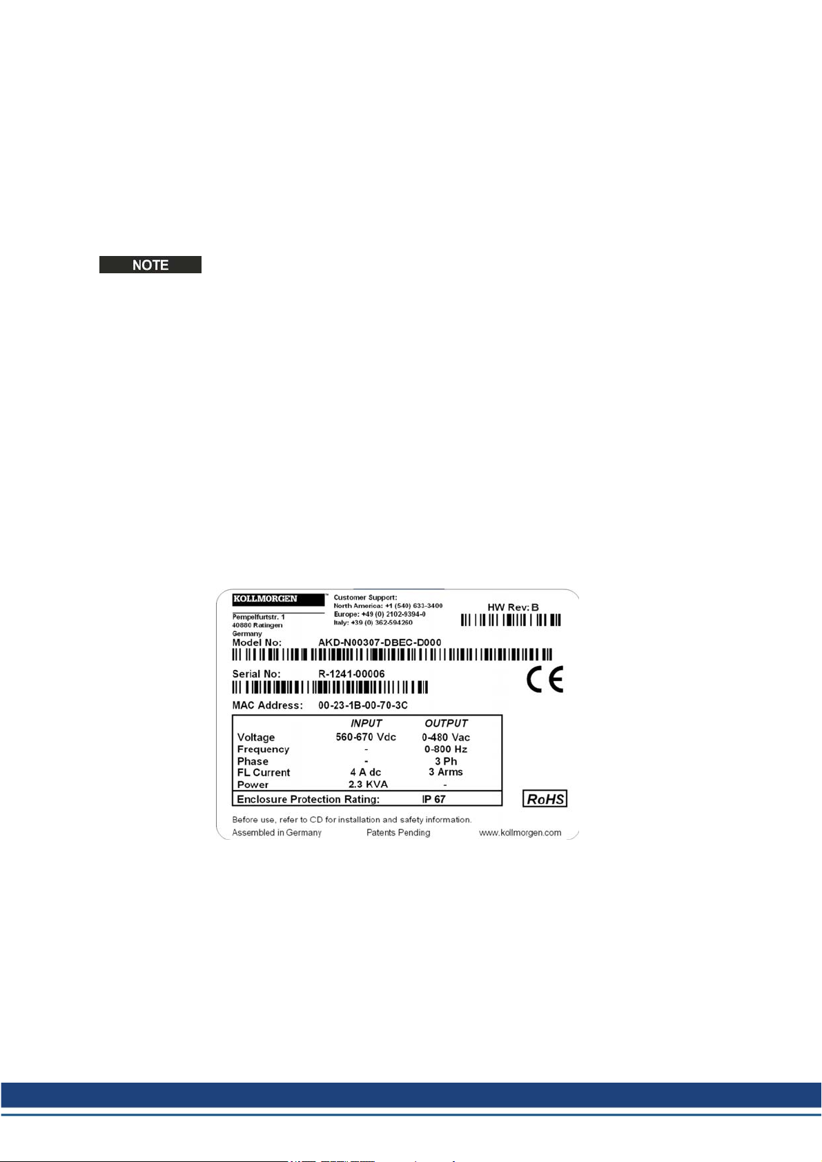
5.2 Nameplate
The nameplate depicted below is attached to the side of the drive, sample data entries are for
a 6A type.
Kollmorgen | December 2014 19
Page 20
AKD-N Installation | 5 Package
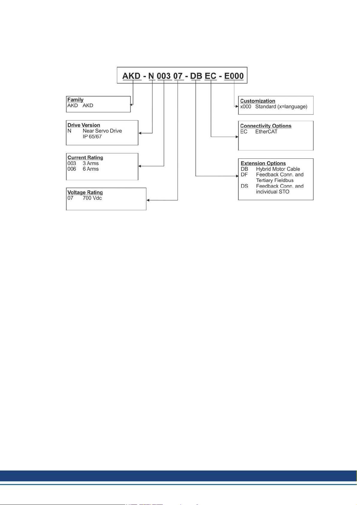
5.3 Part Number Scheme
Use for part numberscheme for product identification only, not for the order process,
because not all combinations of features arepossible, always.
Customization code includes language version of printedmaterial and customer specials.
20 Kollmorgen | December 2014
Page 21

AKD-N Installation | 6 Technical description and data
6 Technical description and data
6.1 The AKD-N Family of Digital Drives 22
6.2 Mechanical Data 23
6.3 Electrical Data 23
6.4 Performance Data 23
6.5 Ambient Conditions, Ventilation, and Mounting Position 24
6.6 Inputs/Outputs 24
6.7 Connectors 25
6.8 Cable Requirements 25
6.9 Cable length definition 26
6.10 Dynamic Braking 27
6.11 Regen circuit 27
6.12 LED Codes 28
6.13 Switch-On and Switch-Off Behavior 29
6.14 Safe Torque Off (STO) 36
Kollmorgen | December 2014 21
Page 22

AKD-N Installation | 6 Technical description and data
6.1 The AKD-N Family of Digital Drives
Available AKD-N versions
Variant (short) Description Current Connectivity
AKD-N-DB
AKD-N-DF
AKD-N-DS
Standard features
l Supply voltage range55 VDC to 800VDC
l Motion bus onboard.
l SFD, Hiperface DSL, Comcoder, ENDAT 2.1 & 2.2, BiSS, HIPERFACE, 1Vp-p Sin-Cos
encoders, incremental encoders support onboard.
l Safe TorqueOff (STO) according to IEC 62061 SIL 2 onboard.
l Use with synchronous servomotors, linear motors, and induction machines.
Hybrid DC power andfieldbus connection.
Hybrid motorpower andfeedback connection.
Hybrid DC power andfieldbus connection.
Hybrid or dual line motor power and feedback
connection. Local tertiary fieldbus interface.
Hybrid DC power andfieldbus connection.
Hybrid or dual line motor power and feedback
connection. Local drive STO input.
3 to 6 A EtherCAT, I/O
3 to 6 A
3 to 6 A
EtherCAT, I/O,
Local Fieldbus
EtherCAT, I/O,
Local STO
Power section
l DCpower supply, voltage range 55VDC to 800 VDC.
l Output stageIGBT module with floating current measurement.
Integrated safety
l Appropriate insulation/creepage distances andelectrical isolationfor safe electrical sep-
aration, per IEC 61800-5-1, between the power input/motor connections and the signal
electronics.
l Temperature monitoring of the drive and motor.
l Motor overload protection: foldback mechanism
l SIL 2 safe torqueoff in accordance with IEC 62061
Operation and parameter setting
l Using the setup softwareWorkBench for system setup via TCP/IP connected to X18 of
the intelligent power supply AKD-C.
Full digital control
l Digital current controller (670 ns)
l Adjustabledigital velocity controller (62.5 µs)
l Software option position controller (250 µs)
Inputs/Outputs
l 3 programmable digital inputs ➜ p. 54
l 1 programmable digital outputs ➜ p. 54
Extensions
l Optional Feedback Connector X5 and Local fieldbus port X6, drive variant "DF", ➜ p. 61
l Optional Feedback Connector X5 and Local STO input X6, drive variant "DS", ➜ p. 61
22 Kollmorgen | December 2014
Page 23

6.2 Mechanical Data
AKD-N Installation | 6 Technical description and data
6.3 Electrical Data
Electrical data Units AKD-N00307 AKD-N00607
Rated supply voltage V= 560 to 680
Standby supply voltage V= 55
Rated input power for continuous operation kVA 1.5 3
Rated input current A 2.8 5.5
Permitted switch on/off frequency 1/h 30
Continuous output current (± 3%):
Continuous output power:
Peak output current (for 5 s, ± 3%) Arms 9 18
Peak output power (for 1 s) kW 2.6 5.2
Motor inductance min. mH 6.3 3.2
Motor inductance max. mH 600 300
Thermal dissipation, output stage disable W max. 6 max. 6
Thermal dissipation at ratedcurrent W 37 71
Efficiency factor % 97 97
Technical data for regen circuit — ➜ p. 27
Motor holding brake current A max. 0.9 max. 1.2
1)
cold plate: (LxWxT) 240x240x10, surrounding temperature: 40°C, supply voltage: 680V
2)
cold plate: (LxWxT) 500x500x10, surrounding temperature: 40°C, supply voltage: 680V
Mechanical data Units AKD
-N00307
Weight kg 1.6
Height mm 75
Width mm 130
Length, housing mm 201
Length, with connectors
andmounting clamps
Optimum cooling situation
(cold plate size definition fulfilled)
Free convection cooling, unmounted Arms 1.8 1.7
Optimum cooling situation
(cold plate size definition fulfilled)
Free convection cooling, unmounted kVA 0.8 0.7
mm 247
Arms 3
kVA 1.3 2.6
1)
AKD
-N00607
2)
6
6.4 Performance Data
Performance Data Units AKD
Switching frequency of output stage kHz 10 8
Voltagerise speed dU/dt kV/µs 7.2
Bandwidth of current controller kHz 2.5
Bandwidth of velocity controller (scalable) Hz 0 to 750
Bandwidth of position controller (scalable) Hz 1 to 250
AKD-
N00307
Kollmorgen | December 2014 23
N00607
Page 24

AKD-N Installation | 6 Technical description and data
6.5 Ambient Conditions, Ventilation, and Mounting Position
Storage ➜ p. 14
Transport ➜ p. 14
Ambient temperature
in operation
Humidity in operation Relative humidity 5 to 95%, no condensation, class 3K4
Site altitude Up to 1000 meters above mean sea level without restriction
Pollution level Pollutionlevel 3 as perIEC 60664-1
Vibrations Class 3M5 according to IEC 60721-3-2
Environmental area IP65/IP67 according to IEC 60529, UL Type 4x
Mounting position All orientations allowed, observe preferred position, ➜ p. 45
Cold plate size Aluminum cold plate minimum size:
Ventilation Free air convection
-10°C to +40 °C under rated conditions
+40 °C to +55 °C with continuous current derating 4 % perKelvin
1,000 to 2,000 meters above meansea level with current derating
1.5%/100 m
AKD-N00307: 350x350x10 mm
AKD-N00607: 500x500x10 mm
The drive operates to full ratings, if the mounting surface for the
cold plate is between -10°C and +85°C and the ambient air temperature is between -10°C and +40°C.
6.6 Inputs/Outputs
Interface Electrical Data
Digital inputs (X3) l as per IEC61131-2 type 1
Digital outputs (X3) l as per IEC61131-2 type 1
STO input (optionDS) l ON: 18 VDC to 30 VDC, 50 mA to 100 mA
STO outputs (X3, option DS) l as per IEC61131-2 type 1
l ON: 15 VDC to 30 VDC, 2 mA to 15 mA
l OFF: -3 VDC to 5 VDC, < 1 mA
l galvanic isolation for 30 VDC
l 2 highspeed inputs: update rate 2 µs
l 1 standard input: update rate 250 µs
l max. 30 VDC, 100 mA
l short circuit proof
l galvanic isolation for 30 VDC
l Update rate 250 µs
l OFF: 0 VDC to 12 VDC, < 50 mA
l galvanic isolation for 60 VDC
l max. 30 VDC, 100 mA
l short circuit proof
l galvanic isolation for 30 VDC
l Update rate 62.5 µs
24 Kollmorgen | December 2014
Page 25

6.7 Connectors
Given voltage andcurrent data arethe lowest values allowed by UL and CE.
* Rated voltage with pollution level 2, use Kollmorgencables only.
AKD-N Installation | 6 Technical description and data
Connector Type Max. Cross Section Current Voltage*
Hybrid IN, X1 Hybrid Connector
(male), 7 poles
Hybrid OUT, X2 Hybrid Connector
(female), 7 poles
Digital I/O, X3 Connector (female),
4 x 0.34mm², 22 awg
3 x 2.5 mm², 14 awg
4 x 0.34mm², 22 awg
3 x 2.5 mm², 14 awg
0.5 A
18 A
0.5 A
18 A
30 V
850V
30 V
850V
8 x 0.34 mm², 22 awg 2 A 30 V
8 poles
Motor, X4 Connector (female),
8 poles
Feedback X5 Connector (male),
4 x 2.5 mm², 14 awg
4 x 1.0 mm², 18 awg
15 A
10 A
630V
30 V
17 x 0.75 mm², 20 awg 3.6 A 63 V
17 poles
STO/Fieldbus, X6 Connector (female),
4 x 0.34 mm², 22 awg 1 A 50 V
4 poles
6.8 Cable Requirements
For information on thechemical, mechanical, and electrical characteristics of the cables
please referto the accessories manual orcontact customer support.
Use Kollmorgen hybrid, motor, and feedback cables only. You will loss system warranty, if
you use hybrid, motor orfeedback cables from a manufacturerother than Kollmorgen.
Cable from Cable type Cable to Cross
AKD-C X20/X21 CCNCN1-0251)AKD-N X1, hybrid 3 x 2.5 mm²
AKD-N X2 CCNNN1-0251)AKD-N X1, hybrid 3 x 2.5 mm²
AKD-N X3 Phoenix SAC-
AKD-N-DB/DS/DF X4 CCJNA1-0151)Motor Power with brake and
AKD-N-DS/DF X4 CM0NA1-0151)Motor Power without brake 4 x 1.5 mm²
AKD-N-DS/DF X4 CM1NA1-0151)Motor Power with brake 4x 1.5 mm²
AKD-N-DS/DF X5 CFSNA1-0021)Motor Feedback SFD 4 x 2 x 0.25 mm²
AKD-N-DS/DF X5 CFCNA1-0021)Motor Feedback Comcoder 7 x 2 x 0.25 mm²
AKD-N-DS/DF X5 CFENA1-0021)Motor Feedback EnDat/BiSS 7 x 2 x 0.25 mm²
AKD-N-DS/DF X5 CFHNA1-0021)Motor Feedback Hiperface 7 x 2 x 0.25 mm²
AKD-N-DF X6 Phoenix NBC-
AKD-N-DS X6 Phoenix SAC-
1)
Followed by length coding. Contact your Kollmorgen sales representative.
2)
Example, similar cables are available from otherdistributors.
8P-M12MS
2)
MSD/5,0-93E
4P-M12MS
2)
section
4 x 0.25 mm²
4 x 0.25 mm²
Digital I/O 8 x 0.25 mm²
4 x 1.5 mm²
Hiperface DSL feedback,
hybrid
2 x 0.75 mm²
2 x 0.34 mm²
2 x 0.75 mm²
Tertiary Fieldbus 2 x 2 x 0.14 mm²
2)
Single Drive STO switch 4 x 0.34 mm²
Kollmorgen | December 2014 25
Page 26

AKD-N Installation | 6 Technical description and data
6.9 Cable length definition
AKD-C offers two separate strings to connect up to 8 AKD-N to each of them. Maximum
total cable length for each string is 100 m. For system topology information refer to ➜ p. 49
Cable
Type
CCNCN1 AKD-C to AKD-N,
CCNNN1 AKD-N to AKD-N,
CCJNA1 AKD-N to Motor,
CMxNA1 AKD-N to Motor
CFyNA1 AKD-N to Motor
Cable usage Available Length (m) Max.
hybrid
hybrid
hybrid
Power
Feedback
Length (m)
3, 6, 12, 24, 36 40
0.25, 0.5, ... , 2.0 (steps 0.25m up to 2m)
2.5, 3.0, ... , 25 (steps 0.5m up to 25m)
0.2, 0.3, ... , 1.0 (steps 0.1m up to 1m)
1.25, 1.5, ... , 2.0 (steps 0.25m up to 2m)
0.2, 0.3, ... , 1.0 (steps 0.1m up to 1m)
1.25, 1.5, ... , 2.0 (steps 0.25m up to 2m)
0.2, 0.3, ... , 1.0 (steps 0.1m up to 1m)
1.25, 1.5, ... , 2.0 (steps 0.25m up to 2m)
25
5
5
5
26 Kollmorgen | December 2014
Page 27

6.10 Dynamic Braking
Dynamic brakingis a method to slow down a servo system by dissipatingthe mechanical
energy driven by the motorback EMF. The AKD-N has a built in advanced dynamic braking
mode which operates fully in hardware. Whenactivated, the drive shorts the motor terminals
in phase with the back EMF (q axis) but continues to operate the non-force producingcurrent
loop(d-axis) with 0 current. This forces all of the dynamic braking current to be stopping current and insures the fastest stopping/amp of motor terminal current.
l When current is not being limited, the mechanical energy is being dissipatedin the motor
resistance.
l When current is being limited, energy is returned to the drive bus capacitors.
l The drive also limits the maximum dynamic braking motorterminal current via the
DRV.DBILIMIT parameter to insure that the drive, motor, and customer load do not see
excessive currents/forces.
Whether andhow the AKD-N uses dynamic brakingdepends on (DRV.DISMODE).
6.11 Regen circuit
When the amount of returned energy builds the bus capacitor voltage up enough theAKD-C
activates the regen circuit to start dumping the returnedenergy in the regen resistor (also
called regenerative or brake resistor). The AKD-C has an internal regen resistor is resistor,
an additional external one can be connected to X14.
External regen resistors are described in the regional AKD Accessories Manual.
AKD-N Installation | 6 Technical description and data
6.11.1 Functional description
When the amount of returned energy builds the bus capacitor voltage up enough theAKD-C
activates the brake chopper to start dumping the returned energy in the regenresistor at the
AKD-C (internally or connected to terminal X14).
90% of the combined power of all the coupled drives is always available for peak and continuous power.
Switch-off on over voltage
The drive that has the lowest switch-off threshold(resulting from tolerances) reports an overvoltage fault if the DC bus threshold is exceeded. The drive power stageis disabled and the
loadcoasts to a stop with the fault message “F501 Bus Over voltage". The AKD-C fault relay
contact (terminals X15/5-6) is openeddue to this fault.
6.11.2 Technical data
Technical data are listed in the AKD -C Installation Manual.
Kollmorgen | December 2014 27
Page 28

AKD-N Installation | 6 Technical description and data
6.12 LED Codes
The built-in LED indicates the status of the drive after the 24 V supply for AKD-C is switched
on. If the AKD-C service connection to the PC or to the PAC doesn't work, then the LED is
the only way to get information.
DANGER
The built-in LED does not safely indicate the real voltage level.
If connectors are unplugged or contacts are touched, there is a danger of
electrical arcing with damage to contacts and serious personal injury.
Always measure the voltage in the DC bus link at connector X14 at AKD-
C and wait until the voltage is below 60 V before handling any component in the decentral servo system.
The LED delivers information with three colors (red, green, yellow) and blink frequency. Specialist can analyze the blink frequency, moreinformation to that can be found in the
WorkBench online help.
Basic information
Color Remarks
Green Enabled and running
blink green/orange Enabledand running with warning
blink orange Safe bus voltage
blink red/orange/green Fault
28 Kollmorgen | December 2014
Page 29

6.13 Switch-On and Switch-Off Behavior
Behavior of “holding brake” function
Drives with an enabled holdingbrake function have a special timing for switching on and off
the output stage. Events that remove the DRV.ACTIVE signal trigger the holding brake to
apply. As with all electronic circuits, the general rule applies that thereis a possibility of the
internal holding brake module failing.
Functional safety, for example with hanging load (vertical axes), requires an additional mechanical brake which must be safely operated, for example by a safety control.
If velocity drops below threshold CS.VTHRESH or timeout occurs duringa stop procedure,
the brake is applied. Set parameter MOTOR.BRAKEIMM to 1 with vertical axes, to apply the
motor holding brake immediately after faults or Hardware Disable.
Safety function STO
With the functional safe function STO, the drive can be securedon standstill using its
internal electronics so that even when power is being supplied, the drive shaft is protected
against unintentional restart. The chapter“Safe Torque Off (STO)” describes how to use the
STO function (➜ p. 36).
6.13.1 Switch-on behavior in standard operation
The diagram below illustrates the correct functional sequence for switchingthe drive on.
AKD-N Installation | 6 Technical description and data
Kollmorgen | December 2014 29
Page 30

AKD-N Installation | 6 Technical description and data
6.13.2 Switch-off behavior
The AKD-C 24 V supply must remain constant. Hardware Enableinput disables all AKD-N
powerstages immediately. Configured Digital Inputs andfieldbus commands can be used to
perform controlled stops.
The control functions Stop, Emergency Stop andEmergency Off are defined by IEC 60204.
Notes for safety aspects of these functions can be found in ISO 13849 and IEC 62061.
The parameter DRV.DISMODE must be set to 2 to implement the different stop categories.
Consult the AKD-N User Guide for configuring the parameter.
WARNING
With vertical load the load could fall. Serious injury could result when the
load is not properly blocked. Functional safety, e.g. with hanging load (vertical axes), requires an additional mechanical brake which must be safely
operated, for example by a safety control.
Set parameter MOTOR.BRAKEIMM to 1 with vertical axes, to apply the
motor holding brake immediately after faults or Hardware Disable.
6.13.2.1 Switch-off behavior using a digital input (controlled stop)
This is a category 2 stop according to IEC 60204. A digital input can beconfigured to bring
the motorto a controlled stop andthendisable the drive and apply the holding brake (if
present). See the AKD-N User Guide forinformation on configuring Digital Inputs.
If velocity drops below threshold CS.VTHRESH or timeout occurs brake is applied.
30 Kollmorgen | December 2014
Page 31

AKD-N Installation | 6 Technical description and data
6.13.2.2 Switch-off behavior using the DRV.DIS command
The enable/disable button in WorkBench issues a drv.dis command internally to the drive.
See AKD-N User Guide for configuring inputs and software commands. Sometimes this
enable signal is called"Software Enable" (SW-Enable).
DRV.DISMODE0Disable axis immediately, if velocity drops below threshold
CS.VTHRESH or timeout occurs brake is applied. Category 0 stop
according to IEC 60204(➜ p. 36).
DRV.DISMODE2Use controlled stop to disable drive, if velocity drops below threshold
CS.VTHRESH or timeout occurs brake is applied. Category 1 stop
according to IEC 60204(➜ p. 36).
If velocity drops below threshold CS.VTHRESH or timeout occurs brake is applied.
Kollmorgen | December 2014 31
Page 32

AKD-N Installation | 6 Technical description and data
6.13.2.3 Switch-off behavior using HW Enable input on AKD-C (uncontrolled stop)
This is a category 0 stop according to IEC 60204. The hardwareenableinput disables the
AKD-N power stage immediately.
If velocity drops below threshold CS.VTHRESH or timeout occurs the motor holding brake is
applied. Set parameter MOTOR.BRAKEIMM to 1 with vertical axes, to apply the motor holding brake immediately after HardwareDisable.
32 Kollmorgen | December 2014
Page 33

6.13.2.4 Switch-off behavior in the event of a fault
The behavior of the drive always depends on the fault type and the setting of a number of different parameters (DRV.DISMODE, VBUS.UVFTHRESH, CS.VTHRESH, and others; see
the AKD-NUser Guide or WorkBench help for more details).See the Drive Fault and Warning
Messages and Remedies section of the AKD-NUser Guide for a table describing the specific behavior of each fault. The follwingpages show examples for the possible fault behaviors.
Switch-off behavior for faults that cause an immediate power stage disable
This is a category 0 stop according to IEC 60204.
AKD-N Installation | 6 Technical description and data
If velocity drops below threshold CS.VTHRESH or timeout occurs the motor holding brake is
applied. Set parameter MOTOR.BRAKEIMM to 1 with vertical axes, to apply the motor holding brake immediately after faults.
Kollmorgen | December 2014 33
Page 34

AKD-N Installation | 6 Technical description and data
Switch-off behavior for faults that cause dynamic braking
This is a category 0 stop according to IEC 60204.
If velocity drops below threshold CS.VTHRESH or timeout occurs brake is applied .
34 Kollmorgen | December 2014
Page 35

AKD-N Installation | 6 Technical description and data
Switch-off behavior for faults that cause a controlled stop
This is a category 1 stop according to IEC 60204.
If velocity drops below threshold CS.VTHRESH or timeout occurs brake is applied .
Kollmorgen | December 2014 35
Page 36

AKD-N Installation | 6 Technical description and data
6.14 Safe Torque Off (STO)
The STO functionality of AKD-N with option "DB" or "DF" is controlledby the AKD-C smart
powersupply via the specific string, where the AKD-N is connected to. This STO topology is
called "Global STO" or "String STO".
AKD-N drives with option "DS" offer an additional connector X6 with a digital STO-Enable
input. This STO functionality is called "Local STO". These drive variants cannot be safety
controlled by the global STO functionality.
6.14.1 Global STO, control via AKD-C
Connector X16 onthe AKD-C offers access to all STO (Safe Torque Off) signals of the
decentral drive system powered by this AKD-C . There is one STO-Enable input andone
STO-Status output for each DC Power string.
The global STO function is described in the AKD-C Installation Manual. Application
examples can be found in the Decentralized System Projecting Guide.
The global STO function uses the following devices: AKD-C, AKD-N without option "DS",
Kollmorgen hybrid connection cable.
In case of using an AKD-N with option "DS" (local STO input), the global STO-Enable signal
will have not influence to this specific drive. The local STO-Status of this drive nevertheless
is monitored in the string STO-Status.
6.14.2 Local STO, control via digital input on AKD-N-DS
Option"DS" on the AKD-N offers local STO-Enable functionality. There is one STO-Enable
input on X6 and one STO-Status output on X3 for the drive. The STO-Status outputs on X3
areavailable only with AKD-N drives with option "DS".
6.14.3 Safety characteristic data
The subsystems are describedwith the following characteristics:
Device Operation
Mode
STO STO single
channel
A very unlikely but possible event can happen, if within a very short time 2 not adjacent
IGBTs will have a short circuit. In such case a movement of maximum an angleof 120° (electrical) can happen. This effect can only happen if the drive is in the function STO. If the total
failurerate of the IGBT is 120 fit normally for such short circuit 60 fit will be valid (50:50
model). By such event 2 specific IGBTs have to fail at same time. The calculation shows a
probability of 1.5 * 10
will be issued fora whole year, this event will only happen every 100 Billionyears.
ISO 13849-1 IEC 62061 PFH
PL d, CAT 3 SIL 2 i.p. i.p. i.p.
-15
perhour (without common cause failure). Even if the STO function
[1/h]
TM[Years] SFF
[%]
36 Kollmorgen | December 2014
Page 37

6.14.4 Response Time
Global STO
The delay from falling edge at global STO Enable input until energy supply to the motors is
interrupted, depends on the number of connected AKD-N to the string. Maximum reaction
time is 10 ms. The more AKD-N are connected to the string, the shorter is the reaction time.
Local STO
The delay from falling edge at local STO Enableinput until energy supply to the motor is interrupted is maximum 10 ms.
6.14.5 Use as directed
The STO function is exclusively intended to provide a functional safe torqueoff of the drive.
To achieve this functional safety, the wiring of the safety circuits must meet the safety
requirements of IEC 60204, ISO 12100 andISO 13849.
If the local STO function is in use, thenthe input STO must be connected to the exit of a
safety control or a safety relay, which at least meets the requirements of PLd, CAT 3 according to ISO 13849.
The 24 VDC supply unit for local STO supply must accord to PELV/SELV (EN 60204-1)
requirements.
AKD-N Installation | 6 Technical description and data
6.14.6 Prohibited use
The STO function must not be used if the drive is to be made inactive for the followingreasons:
l Cleaning, maintenance andrepairoperations, longinoperative periods. In such cases, the
entire system should be disconnected from the supply and secured (main switch).
l Emergency-Off situations. In an Emergency-Off situation, the main contactor is switched
off (by the Emergency-Off button).
l Wiring the system with hybrid cables from other manufacturers than Kollmorgen is not
allowed.
l Changing cables or connectors is not allowed.
l Do not use STO Status signals for functional safety.
6.14.7 Enclosure, wiring
Observe the requiredambient conditions as describedin chapter "Ambient Conditions, Ventilation, and Mounting Position" (➜ p. 24). The AKD-N can beused in an environment that
meets IP67.
The cables must be laid durably (firmly), protected from outside damage (forexample, by laying the cable in a duct), placed in different sheathed cables, or protected individually by
grounding connection.
Wiring must meet the requirements of the standard IEC 60204-1.
Kollmorgen | December 2014 37
Page 38

AKD-N Installation | 6 Technical description and data
6.14.8 Local STO safety instructions
WARNING
The drive cannot hold a vertical load when STO is active. Serious injury
could result when load is not properly blocked. Drives with a suspended
load must have an additional safe mechanical blocking (for instance, by a
motor-holding brake).
The drives have not to be used for driving elevators.
CAUTION
In case of a specific double fault within a very short time (see ➜ p. 36) a
single movement of maximum an angle of 120° (electrical) can happen.
This effect can only happen if the drive is in the function STO.
Even if the STO function will be issued for a whole year, this event will
only happen every 100 Billion years.
CAUTION
The drive might restart automatically after power on, voltage dip or interruption of the supply voltage, depending on the parameter setting.
Risk of death or serious injury for humans working in the machine.
If the parameter DRV.ENDEFAULT is set to 1, then place a warning sign
to the machine (Warning: Automatic Restart at Power On) and ensure,
that power on is not possible, while humans are in a dangerous zone of
the machine. In case of using an undervoltage protection device, you
must observe EN 60204-1:2006 chapter 7.5 .
CAUTION
The STO function does not provide an electrical separation from the
power output. There is a danger of electrical shock and personnel injury.
If access to the motor power terminals is necessary, the drive must be disconnected from AKD-C considering the DC Bus discharging time.
If the safety function STO is automatically activated by a control system, then make sure
that the output of the control is monitored for possible malfunction. The monitoring canbe
used to prevent a faulty output from unintentionally activating the STO function. Since the
local STO function is a single-channel system, erroneous engagingwill not be recognized.
It is not possible to perform a controlled brake if the drive controlledSTO-Enable is off. If controlledbraking before the use of the STO function is necessary, the drive must be braked and
the input STO must be separated time-delayed from +24 V .
The STO Status signals areinformal and not relevant for functional safety.
38 Kollmorgen | December 2014
Page 39

6.14.9 Technical data and pinout local STO
The local STO input is not compatible with IEC 61131-2.
STO-Enable input l Input does not match IEC61131-2
l ON: 18 VDC to 30 VDC, 100mA
l OFF: 0 VDC to 12 VDC, < 50 mA
l Galvanic isolation for 250 VDC
l Tolerated OSSD pulse duration 0.3 ms
STO-Status outputs l As per IEC61131-2 type 1
l Max. 30 VDC, 100 mA
l Galvanic isolation for 250 VDC
24 VDC Power supply l PELV/SELV acc. to EN 60204-1
l Output 24 VDC +/-10%
Wiring diagram local STO-Enable
M12, A-coded X6 Pinout Description
1 STO-Enable+
2 STO-Enable -
AKD-N Installation | 6 Technical description and data
3 n.c.
4 n.c.
Wiring diagram local STO-Status
M12, A-coded X3 Pinout Description
1,2 see "Digital Output" (➜ p. 56)
3 STO Status -
4 STO Status +
5,6,7,8 see "Digital Output" (➜ p. 56)
Kollmorgen | December 2014 39
Page 40

AKD-N Installation | 6 Technical description and data
6.14.10 Functional description local STO
With AKD-N with option DS, an additional digital input (STO) releases the power output
stage of the drive as long as a 24 V signal is appliedto this input. Whenthe local STO function (Safe Torque Off) is not needed, then the input STO must be connected directly to +24
VDC. The function is then bypassed and cannot be used.
The global STO signal will have no influence to this drive. The local STO input on the AKD-N
has no influence to the global STO as well.
Local
STO-Enable
0 V no high yes no
0 V yes high yes no
+24 V no low no no
+24 V yes low no yes
When STO function is engaged during operation by separating input STO-Enable from 24 V,
the connected motorslows down without control.
Use the followingfunctional sequence whenthe STO function is used:
1. Brake the drive in a controlled manner (speed setpoint = 0 V).
2. When speed = 0 rpm, disable the drive (enable = 0 V).
3. If a suspended load is present, block the drive mechanically.
4. Activate the STO function.
It is not possible to perform a controlled brake if the drive STO-Enable is off.
If controlled brakingprior to the use of the STO function is necessary, the drive must be
braked first and the input STO must be separated from +24 V time-delayed.
6.14.10.1 Signal diagram (sequence)
The diagram below shows how to use STO function for a safe drive stop and fault free operation of the drive. This sequence is valid for local and global STO functionality.
1. Brake the drive in a controlled manner (speedsetpoint = 0 V).
2. When speed = 0 rpm, disable the drive (Enable = 0 V).
3. Activate the STO function (local STO-Enable= 0 V)
4. For restart you must reset the safety device.
HW Enable
String
Local
STO-Status
Safety acc.
to SIL2
Drive can
produce Torque
40 Kollmorgen | December 2014
Page 41

6.14.11 Functional test
You must test the safe torque off function after initial start of the drive, after each interference
into the wiring of the drive, or after exchangeof oneor several components of the drive.
6.14.11.1 Global STO
First Method:
1. Stop drives in the string with setpoint 0 V. Keepdrives enabled.
DANGER: Do not enter hazardous area!
2. Activate the global STO function forexample by openingprotective screen of the string,
where the drives are connected (voltage at AKD-C X16/6 or X16/8 0V).
3. The AKD-C fault contact opens, the corresponding string STO-Status message (X16/1 or
X16/2)changes the voltage level, the drives lose torque and slow down to zero speed
without control.
Second Method:
1. Stop all drives in the string with setpoint 0 V, disable the string.
2. Activate the global STO function, for example, by opening protective screen (voltage at
AKD-C X16/6 or X16/8 0V)
3. The corresponding string STO-Status message (X16/1 or X16/2) changes the voltage
level, the string cannot be enabled.
AKD-N Installation | 6 Technical description and data
6.14.11.2 Local STO
First Method:
1. Stop the drive with setpoint 0 V. Keep drive enabled.
2. Activate the local STO function for example by opening protective screen of the drive,
3. The drive lose toque and slows down to zerospeed without control.
Second Method:
1. Stop the drive with setpoint 0 V, disable drive.
2. Activate the STO function, for example, by opening protective screen(voltage at AKD-N
3. The drive cannot be enabled.
DANGER: Do not enter hazardous area!
(voltage at AKD-N X6/1 0V).
X6/1 0V)
Kollmorgen | December 2014 41
Page 42

AKD-N Installation | 6 Technical description and data
6.14.11.3 Local STO application example
The sample application below shows door guarding and emergency stop, controlledby KollmorgenKSM safety module to switch the local STO-Enable input of an AKD-N-DS drive
according to SIL2, PLd.
For detailledapplication examples refer to the Decentralized System Projecting Guide.
Refer to the KSM safety modules documentation forpinout andfunctionality of the KollmorgenKSM Modules. These documents can be downloaded from the Kollmorgen website.
42 Kollmorgen | December 2014
Page 43

AKD-N Installation | 7 Mechanical Installation
7 Mechanical Installation
7.1 Important Notes 44
7.2 Temperature Management 44
7.3 Mechanical Drawings 45
Kollmorgen | December 2014 43
Page 44

AKD-N Installation | 7 Mechanical Installation
7.1 Important Notes
CAUTION
There is a danger of electrical shock by high EMC level which could result in injury, if the drive (or the motor) is not properly EMC-grounded.
CAUTION
AKD-N Drives may have hot surfaces during operation. The housing can
reach temperatures above 80°C. Risk of minor burns! Measure the temperature, and wait until the housing has cooled down below 40°C before
touching it.
Ensure free space of minimum 50 mm to all sides of the drive.
Protect the drive from impermissible stresses. In particular, do not let any components
become bent or any insulation distances altered during transport and handling. Avoid contact
with electronic components and contacts.
The drive will switch itself off in case of overheating. Ensure that the mountingspace
matches the requirements (➜ p. 24).
Do not mount devices that produce magnetic fields directly beside the drive. Strong magnetic
fields can directly affect internal components. Install devices which produce magnetic field
with distance to the drives and/orshield themagnetic fields.
An optimized thermal strategy is mandatory for AKD-N performance. Observe the information given in the Decentralized System Projecting Guideand in chapter "Temperature Man-
agement" (➜ p. 44)
7.2 Temperature Management
The possible continuous output current andoutput powerdepends on the cooling situation for
the AKD-N. For a detailedcalculationof temperature behavior of the decentralized drive system based on the special machinery architecture, please contact the Kollmorgen customer
support.
Optimum cooling situation to reach rated power:
Cold plate requirements with 40°C surrounding temperature at 680 VDC supply voltage:
l AKD-N 3 A : 240mm x 240 mm x 10 mm
l AKD-N 6 A : 500mm x 500 mm x 10 mm
For a rough overview the three level rating below may help.
1. Optimum cooling situation
Cold plate size definition fulfilled, no additional heat sink required
2. Medium cooling situation
Example: 65% cooling plate available
Use the optional small heat sink (40mm height) to reach optimum situation
3. Bad cooling situation
Example: 50% cooling plate available
Use the optional big heat sink (50mm height) to reach optimum situation.
The heat sink variants are described in the regional accessories manual.
44 Kollmorgen | December 2014
Page 45

7.3 Mechanical Drawings
7.3.1 Dimensions AKD-N, preferred mounting
Material:
l Four mounting clamps (part of delivery)
l Four M5 hexagon socket screws to ISO 4762, use 4 mm T-handle Allenkey
l Heat conducting film(order code 849-373000-04)
Ensurefreespace of minimum 50 mm to all sides of the AKD-N.
AKD-N Installation | 7 Mechanical Installation
Kollmorgen | December 2014 45
Page 46

AKD-N Installation | 7 Mechanical Installation
7.3.2 Dimensions AKD-N with optional heat sink, preferred mounting
Material:
l Four mounting clamps (part of delivery)
l Four M5 hexagon socket screws to ISO 4762, use 4 mm T-handle Allenkey
l Four M4x16 hexagon socket screws to ISO 4762 (part of delivery), use 3 mm T-handle
Allen key
l Heat conducting film (order code849-373000-04)
l Heat sink 40 mm (option, see regional Accessories Manual)
l Heat sink 50 mm (option, see regional Accessories Manual)
Ensurefreespace of minimum 50 mm to all sides of the AKD-N.
46 Kollmorgen | December 2014
Page 47

AKD-N Installation | 8 Electrical Installation
8 Electrical Installation
8.1 Important Notes 48
8.2 Guide to Electrical Installation 48
8.3 System Topology of a Decentralized Servo System 49
8.4 Wiring 50
8.5 Connection Overview 51
8.6 Hybrid Connection (X1, X2) 54
8.7 I/O Connection (X3) 54
8.8 Motor Power Connection (X4) 57
8.9 Motor Brake Connection (X4) 58
8.10 Motor Feedback Connection (X4, X5) 59
8.11 Optional Connector (X6) 61
Kollmorgen | December 2014 47
Page 48

AKD-N Installation | 8 Electrical Installation
8.1 Important Notes
DANGER
Never remove electrical connections to the drive while it is live. There is a
danger of electrical arcing with damage to contacts and serious personal
injury. Capacitors can still have dangerous voltages present up to 7
minutes after switching off the supply power. Always measure the voltage
in the DC bus link at connector X14 at AKD-C and wait until the voltage is
below 60 V before handling components. Control and power connections
can still be live, even if the motor is not rotating.
The built-in LED does not indicate the real voltage level.
CAUTION
Since the leakage current to PE is more than 3.5 mA, in compliance with
IEC 61800-5-1 the PE connection must either be doubled or a connecting
cable with a cross-section >10 mm² must be used. There is a danger of
electrical shock with possible personal injury. Deviating measures according to regional standards might be possible.
WrongDC Bus link voltage, unsuitable motor or wrong wiring will damage the drive. Check
the combination of drive and motor. Compare the rated voltage and current of the units. Implement the wiringaccording to the connection diagrams: ➜ p. 51.
It is permissible to use the setup software to alter the settings of the drive. Any other alterations will invalidate the warranty.
8.2 Guide to Electrical Installation
Install the drive electrical system as follows:
1. Select cables (➜ p. 25.)in accordance with the planned system topology (➜ p. 49).
2. Install grounding (PE) and groundthe drive.
Ground the mountingplate, motor housing and CNC-GND of the control system.
3. Wire the drive:
The connectors are close to each other on the drive. To ensure simple handling, observe the
connector mounting sequence: X2 - X1 - X4 - X5 - X3 - X6
o
Connect the hybrid power cable betweenAKD-C X20 orX21 and AKD-N X1, max.
length 40 m.
o
Connect the hybrid power cables between the AKD-N drives X1/X2, max. length 25 m.
o
Dual line connection:
Connect the motor cable to X4, max. length 5 m.
Connect the feedback device to X5 , max. length 5 m.
o
Single line connection:
Connect the hybrid motor cable to X4, max. length 5 m.
4. Check the wiring against the plannedsystem topology diagrams (➜ p. 49).
48 Kollmorgen | December 2014
Page 49

AKD-N Installation | 8 Electrical Installation
8.3 System Topology of a Decentralized Servo System
8.3.1 System limits
String length: maximum 100 m total cable length perstring
Number of AKD-N: maximum 8 per string
observe total power/current restrictions described in the Decentralized System Projecting Guide
Sum of output current of
string 1 and string 2: 17 A, calculate coincidence factor of the axes
Standby Power: Standby power is limited to 260 W at 24 V for both strings. This
powermust supply all AKD-N (8 W each) and the remaining
powercan beused for motor holding brakes.
8.3.2 Example
Kollmorgen | December 2014 49
Page 50

AKD-N Installation | 8 Electrical Installation
8.4 Wiring
DANGER
There is a danger of electrical arcing which can cause serious personnel
injury. Only install and wire the equipment when it is not live, that is, when
neither the electrical supply nor the 24 V auxiliary voltage nor the supply
voltages of any other connected equipment is switched on.
Make sure that the cabinet is safely disconnected (for instance, with a
lock-out and warning signs). The individual voltages are switched on for
the first time during setup.
The built-in LED does not safely indicate the real voltage level. Always
measure the voltage in the DC bus link at connector X14 at AKD-C and
wait until the voltage is below 60 V before handling any component in the
decentral servo system.
Only professional staff who are qualified in electrical engineering are allowedto install the
drive. Wires with color green with one or more yellow stripes must not be used other than for
protective earth (PE) wiring.
The groundsymbol, which you will find in all the wiring diagrams, indicates that you must
take care to provide anelectrically conductive connection with the largest feasible surface
area between the unit indicated and the mounting plate in the control cabinet. This connection
is for the effective grounding of HF interference, and must not be confused with the PE-symbol (PE = protective earth, safety measure as perIEC 60204).
Use the followingconnection diagrams:
Overview AKD-N variant DB ➜ p. 52
Overview AKD-N variant DS/DF ➜ p. 53
DC powerand Fieldbus connection ➜ p. 54
Digital inputs and outputs ➜ p. 54
Motor Power ➜ p. 57
Motor Brake ➜ p. 58
Motor Feedback ➜ p. 59
Tertiary motion bus interface ➜ p. 61
Local STO ➜ p. 61
50 Kollmorgen | December 2014
Page 51

8.5 Connection Overview
8.5.1 Connector assignment AKD-Nzzz07-DB
AKD-N Installation | 8 Electrical Installation
8.5.2 Connector assignment AKD-Nzzz07-DF/DS
Kollmorgen | December 2014 51
Page 52

AKD-N Installation | 8 Electrical Installation
8.5.3 Connection diagram AKD-Nzzz07-DB
52 Kollmorgen | December 2014
Page 53

8.5.4 Connection diagram AKD-Nzzz07-DF/DS
AKD-N Installation | 8 Electrical Installation
Kollmorgen | December 2014 53
Page 54

AKD-N Installation | 8 Electrical Installation
8.6 Hybrid Connection (X1, X2)
Connector X1 (Hybrid In) Connector X2 (Hybrid Out)
Pinout
Pin Usage X1 Usage X2
A not connected not connected
B - DC_ST - DC_ST
C +DC_ST +DC_ST
PE PE PE
1 Receive - Transmit 2 Transmit - Receive 3 Receive + Transmit+
4 Transmit + Receive +
8.7 I/O Connection (X3)
M12, A-coded X3 Description Abbreviation Function
* STO-Status signals areavailable for AKD-N with option "DS" only.
The DCOM3 line should be connected to the 0V of the I/O supply when using sensors of type
"Source" with digital inputs.
The DCOM3 line should be connected to the 24V of the I/O supply when using sensors of
type "Sink" with digital inputs.
1 Digital Input 1 DIGITAL-IN 1 Programmable
2 Digital Input 2 DIGITAL-IN 2 Programmable
3* STO-Status - STO-Status - local STO-Status
4* STO-Status + STO-Status + local STO-Status
5 Digital Input 3 DIGITAL-IN 3 Programmable
6 Digital Common DCOM3 Common line
for pins 1, 2, 5
7 Digital Output 1- DIGITAL-OUT1- Programmable
8 Digital Output 1+ DIGITAL-OUT1+ Programmable
54 Kollmorgen | December 2014
Page 55

8.7.1 Digital Inputs
The drive provides 3 digital inputs. These can be used to initiate pre-programmed functions
that are stored in the drive. A list of these pre-programmed functions is included in the
WorkBench. If an input is programmed, it must be saved to the drive. By default,all inputs are
not programmed (off). For more information refer to the setup software.
Depending on the selected function, the inputs are highor low active. The inputs can be used
with switched +24V (source type) or switched GND (sink type).
Digital Input Wiring Diagram:
AKD-N Installation | 8 Electrical Installation
Digital Inputs 1 and 2
These inputs are particularly fast andare therefore suitable forlatch functions, for example.
Technical characteristics:
l Floating, reference common lineis DCOM3
l Sink or Source type sensors possible
l High: 15 to 30 V / 2 to 15 mA , Low: -3 to +5 V / <1 mA
l Update rate: Hardware 2 µs
Digital Input 3
Choose the function you require in WorkBench.
Technical characteristics:
l Floating, reference common lineis DCOM3
l Sink or Source type sensors possible
l High: 15 to 30 V / 2 to 15 mA , Low: -3 to +5 V / <1 mA
l Update rate: Software 250µs
Kollmorgen | December 2014 55
Page 56

AKD-N Installation | 8 Electrical Installation
8.7.2 Digital Output
The drive supplies one programmable digital output and the permanent STO-Status output for
drives with "DS" option. For the programmable output choose the required function in the
setup software. Messages from pre-programmed functions stored in the drive can be output
here. A list of these pre-programmed functions can be foundin the setup software. If an output is to be assigned to a pre-programmed function, thenthe parameterset must be saved in
the drive. By default,the output is not programmed (off). For more informationrefer to the
setup software.
Technical characteristics:
l STO-Status signal is available for AKD-N with option "DS" only.
l 24 V , 20 VDC to 30 VDC
l All digital outputs are floating, max.100 mA
l Can be wiredas active low or active high(see examples below)
l Update rate: 250 µs
Wiring diagram:
56 Kollmorgen | December 2014
Page 57

AKD-N Installation | 8 Electrical Installation
8.8 Motor Power Connection (X4)
Together with the motor supply cable and motor winding, the poweroutput of the drive forms
an oscillating circuit. Characteristics such as cable capacity, cablelength, motor inductance, and frequency determine the maximum voltage in the system.
The AKD-N drive is able to protect the connected motor from overloading, if the parameters
areset correctly and the thermal protection sensor is connected and supervised. With Kollmorgenmotors the valid data are automatically set by the internal motor database. With
motors from other manufacturers the data from the nameplate must be entered to the referringfields in the motor view of the Kollmorgen setupsoftware WorkBench.
The dynamic voltage rise can lead to a reduction in the motor operating life and, on unsuitable
motors, to flashovers in the motor winding.
l Only install motors with insulation class F (acc. to IEC60085) orabove.
l Only install Kollmorgen cables that meet the requirements ➜ p. 25.
8.8.1 Connector X4 AKD-Nzzz07-DB/DS/DF, hybrid, single line
Motors with single line connection (motor power lines, motor holding brake lines and motor
feedback lines combined in one hybrid cable)can beconnected to X4 of the AKD-Nzzz07DB or -DS variants.
X4 Signal Description
A, B, C, D ... Feedback (➜ p. 59), Brake (➜ p. 58)
1 U Motor phase U
2 PE Protective earth (motor housing)
3 W Motorphase W
4 V Motor phase V
8.8.2 Connector X4 AKD-Nzzz07-DF/DS, dual line
Motors with dual lineconnection (motor power lines and motorholdingbrake lines in one
cable, motorfeedback lines in a separate cable) can be connected to X4 and X5 of the AKDNzzz07-DF and -DS variants.
X4 Signal Description
A, B, C, D ... Brake (➜ p. 58)
1 U Motor phase U
2 PE Protective earth (motorhousing)
3 W Motor phase W
4 V Motor phase V
Kollmorgen | December 2014 57
Page 58

AKD-N Installation | 8 Electrical Installation
8.9 Motor Brake Connection (X4)
A 24 V holding brake in the motor canbe controlled directly by the drive. The brake only
works with sufficient 24 V voltage level. Check voltagedrop, measure thevoltage at brake
input and check brake function (brake and nobrake). Maximum current for the motor brake is
1 A with AKD-N00307and 1.5 A with AKD-N00607.
The stand-by power supply from AKD-C limits the number of brakes in the system. Observe
the projecting hints for system topology and limits in the Projecting Guide.
CAUTION
This function does not ensure functional safety. Functional safety requires
and additional, external mechanical brake, operated by a safety controller. Set parameter MOTOR.BRAKEIMM to 1 with vertical axes, to
apply the brake immediately after faults or Hardware Disable.
The brake function must be enabledand configured with parameter using WorkBench, for
details refer to the online help.
Single line hybrid cable and dual line motor power cable use two lines for motorholdingbrake
connection.
Single Line Dual Line
X4 Signal Description
A +BR Motor holdingbrake, positive
B -BR Motor holding brake, negative
C, D ... SingleLine: Feedback (➜ p.
1,2,3,4 ... Motor power (➜ p. 57)
59)
Dual Line: unused
58 Kollmorgen | December 2014
Page 59

AKD-N Installation | 8 Electrical Installation
8.10 Motor Feedback Connection (X4, X5)
Every closed servo system normally requires at least one feedback device for sending actual
values from the motor to the drive. Depending on thetype of feedback device used, information will be fed back to the drive using digital or analog means.
AKD-N supports the most common types of feedback device. Feedback functions are
assigned with parameters in WorkBench, the setup software. Scalingand other settings are
also performed in WorkBench. For a detailed description of the parameters, please refer to
the WorkBench onlinehelp.
Motors with single line connection (motor power lines, motor holding brake lines and motor
feedback lines combined in one hybrid cable)can beconnected to X4 of the AKD-Nzzz07DB or -DS variants.
Motors with dual lineconnection (motor power lines and motorholdingbrake lines in one
cable, motorfeedback lines in a separate cable) can be connected to X4 and X5 of the AKDNzzz07-DF and -DS variants.
8.10.1 Connector X4 AKD-Nzzz07-DB/DS/DF, hybrid, single line
X4 Signal Description
A,B ... Brake (➜ p. 58)
C COM- Feedback, negative
D COM+ Feedback, positive
1,2,3,4 ... Motor power (➜ p. 57)
Support for SFD3 and Hiperface DSL feedback systems.
Kollmorgen | December 2014 59
Page 60

AKD-N Installation | 8 Electrical Installation
8.10.2 Connector X5 AKD-Nzzz07-DF/DS, dual line
X5 SFD
(4 lines)
BiSS B
(analog)
BiSS C
(digital)
EnDAT
2.1
EnDAT
2.2
Hiper-
face
Sine
Enc.
+Hall
Incr.
Enc.
+Hall
1 - - - - - - Hall U Hall U
2 - CLK+ CLK+ CLK+ CLK+ - Hall V Hall V
3 - CLK- CLK- CLK- CLK- - Hall W Hall W
4 - - - - - *1 - 5 - - - - - *1 - 6 COM+ DAT+ DAT+ DAT+ DAT+ DAT+ Zero+ Zero+
7 COM- DAT- DAT- DAT- DAT- DAT- Zero- Zero8 - Thermal control (+)
9 - Thermal control (-)
10 +5 V +5 V +5 V +5 V +5 V +8 to +9 V +5 V +5 V
11 0 V 0 V 0V 0 V 0 V 0 V 0 V 0 V
12 - A+ - A+ - SIN+ A+ A+
13 - A- - A- - SIN- A- A14 - B+ - B+ - COS+ B+ B+
15 - B- - B- - COS- B- B16
17
CLK = CLOCK, DAT = DATA
BiSS Mode C interface from Renishaw (model Resolute RA26B)
Hiperface *1=pins 4 and 5 externally connected
60 Kollmorgen | December 2014
Page 61

8.11 Optional Connector (X6)
8.11.1 Pinout AKD-Nzzz07-DF
The additional connector X6 with AKD-N-DF device variants allows connection to fieldbus
slave devices that are controlled by the system master.
M12, D-coded X6 Description
AKD-N Installation | 8 Electrical Installation
1 Transmit +
2 Receive+
3 Transmit -
4 Receive-
8.11.2 Pinout AKD-Nzzz07-DS
An additional digital input (STO-Enable) releases the power output stage of the drive as long
as a 24V signal is applied to this input. The local STO-Enableinput is galvanically isolated
andneed external 24 VDC supply (PELV/SELF).
For detailleddescription of STO interface and functionality refer to "Safe TorqueOff (STO)"
(➜ p. 36).
Wiring diagram local STO-Enable
M12, A-coded X6 Description
1 STO-Enable+
2 STO-Enable -
3 n.c.
4 n.c.
Kollmorgen | December 2014 61
Page 62

AKD-N Installation | 9 Setup
9 Setup
9.1 Important Notes 63
9.2 Setup software WorkBench 64
9.3 Initial System Test 65
9.4 Fault and Warning Messages 66
62 Kollmorgen | December 2014
Page 63

9.1 Important Notes
Beforetesting andsetup, the manufacturer of the machine must generate a risk assessment
for the machine and take appropriate measures so that unforeseen movements cannot cause
injury or damageto any person orproperty.
Only professional personnel with extensive knowledge in the fields of electrical engineering
anddrive technology are allowed to test and set up the drive.
DANGER
The equipment produces potentially lethal voltages up to 900 V. Risk of
electrical shock.
Check that all connection components that are live in operation are safely
protected against bodily contact.
Never remove the electrical connections to the drive while it is live.
Capacitors can still have dangerous residual charges up to 7 minutes
after switching off the supply voltage.
AKD-N Installation | 9 Setup
WARNING
The drive might restart automatically after power on, depending on the
parameter setting. Risk of death or serious injury for humans working in
the machine. If parameter DRV.ENDEFAULT is set to 1, then place a
warning sign to the machine (Warning: Automatic Restart at Power On)
and ensure, that power on is not possible, while humans are in a dangerous zone of the machine.
CAUTION
The heat sink of the drive can reach temperatures up to 80°C in operation. Risk of light burns. Check the heat sink temperature before handling the drive. Wait until the heat sink has cooled down to 40 °C before
touching it.
Additional informationon setting upthe equipment:
l Programming parameters andcontrol loop behavior are describedin the online help of the
setup software.
l Kollmorgencan provide training courses for the decentral drive system upon request.
Kollmorgen | December 2014 63
Page 64

AKD-N Installation | 9 Setup
9.2 Setup software WorkBench
The setupsoftware WorkBench for AKD-N and AKD-C devices is intended to be used for
altering and saving the operatingparameters for the decentral drive system. The attached
device can be set up with the help of this software, and duringthis procedure the drive can be
controlled directly by the service functions.
You can find the setupsoftware on the accompanying DVD andin the download area of the
Kollmorgen website.
Kollmorgen offers training and familiarization courses on request.
Only professional personnel who have the relevant expertise (➜ p. 11) are permitted to carry
out online parametersetting for a drive that is running. Sets of data that have beenstoredon
data media are not safe against unintended alteration by otherpersons. Unexpected move
could bethe result if you use unchecked data. After loadinga set of data you must therefore
always check all parameters before enabling the drive.
For most applications, you can use a PC and WorkBench (the drive setup software) to set up
the operating conditions andparameters for your drive. The PC is connected to the AKD-C
by an Ethernet cable (see AKD-C Installation Manual). The setup software provides the com-
munication between the PC, the AKD-C and the AKD-N.
With WorkBench every drive that is connected to the same AKD-C as the PC is visible. and
controllable
You can select a drive out of the list, alter parameters, and instantly observe the effect on the
drive, since thereis a continuous (online)connection to the drive. You can also read important actual values from the selected drive, which aredisplayed on the monitor of the PC (oscilloscope functions).
You can save sets of data ondata media (archiving) and load them into other drives or use
them for backup. You can also print out the data sets.
64 Kollmorgen | December 2014
Page 65

9.3 Initial System Test
9.3.1 Unpacking, mounting, and wiring
l Unpack the drive and accessories. Observe the safety instructions in the documentation.
l Mount the drive (➜ p. 43ff).
l Connect the AKD-N via the hybrid cables to the AKD-C (➜ p. 47ff).
l Connect Motor (➜ p. 57) and feedback (➜ p. 59)(single line ordual line connection
depending on motor and AKD-N version).
l Make sure youhave on hand the following information about the drive components:
o
rated mains supply voltage
o
motor type (motor data, if the motortype is not listed in the motordatabase)
o
feedback unit built into the motor (type, poles/lines/protocol)
o
moment of inertia of the load
l Connect a PC with the installed WorkBench setup software to the AKD-C connector
X18. See AKD-C Installation Manual for more information.
9.3.2 Set IP address
The Node address can be set with the WorkBench setup software or via the used fieldbus.
AKD-N Installation | 9 Setup
9.3.3 Confirm connections
Switch on 24 VDC logic power for the system through the AKD-C X13 connector (mains supply voltage is not needed forcommunications).
Confirm that the link LEDs on the AKD-C are both illuminated.
While the PC is connecting, yourstatusbar will show the followingacquiring icon:
Wait for this icon to changeto the limited functionality icon (this process can take up to one
minute).
Although Windows displays this limited functionality icon for the drive connection, the PC
can communicate fully with the drive. Using WorkBench, you can now configure the drive
throughthis connection.
Kollmorgen | December 2014 65
Page 66

AKD-N Installation | 9 Setup
9.3.4 Install and start WorkBench
WorkBench installs automatically from the DVD included with the drive. WorkBench is also
available on theKollmorgen Web site: www.kollmorgen.com.
Once installation is complete, click the WorkBench icon to start the program. WorkBench
will show a list of all the drives that it can find connected to the AKD-C. Select the drive you
wish to configure and thenclick Next.
If multiple drives are detected, a drive can be uniquely identified usingone of the following
methods:
1. The MAC address of the drive. This address is printed on the sticker on theside of the
drive.
2. The name of the drive. The drive name is set using WorkBench. A new drive defaults to
“No_Name.”
3. Blinking the display. Select a drive and click Blink to force the LED of the drive to blink on
andoff for 20 seconds.
9.3.5 Enable the drive using the setup wizard
Once a connection to the drive has been established, the AKD Overview screen appears.
Yourdrive appears in the navigationarea on the left of the screen. Right click on yourdrive
name andselect Setup Wizard from the drop-down menu. The Setup Wizard guides you
throughthe initial drive configuration, which includes a simple test motion.
After completingthe Setup Wizard, yourdrive should be enabled. If the drive is not enabled,
check the following:
1. The hardware enable (HW) for the drive strings must be in the enabled state (pin 3 on
AKD-C X15 connector).
2. The software enable (SW) must be in the enabled state. Activate using the Enable/Dis-
able button on the upper toolbar on WorkBench or in the Overview screen.
3. No faults may be present (click the Clear Fault button on the upper tool bar to clear any
faults).
The status of HW enable, SW enable, andFaults is displayed in the lowertoolbar of the
WorkBench software. The drive is connected if the lower right corner shows Online.
You can now use the Settings View in WorkBench to complete advanced configuration of
your drive.
9.4 Fault and Warning Messages
When a fault occurs, the AKD-C fault relay is opened, the output stage is switched off (motor
loses all torque), or the load is dynamically braked. If a warning is issuedprior to the fault, the
warning has the same number as the associated fault. Warnings do not trip the powerstage
of the drive or fault relay output.
Within a stringseveral drives might show warnings or faults. All actual faults and warnings
can be monitored with the WorkBench setup software via the AKD-C service interface or
with the usedmotion controller software connected via the AKD-C motionbus interface.
More information about fault messages, remedy and clearing faults can be found in the
WorkBench online help.
66 Kollmorgen | December 2014
Page 67

10 Index
AKD-N Installation | 10Index
Installation
Electrical 47
Mechanical 43
A
Abbreviations 9
AKD Family 22
Ambient temperature 24
C
Cable and Wire Requirements 25
CE conformance 17
Connection Diagrams
DB Variant 52
DF/DS Variants 53
Connection Overview 51
Connector Assignments
DB Variant 51
Connectors 25
D
Digital inputs 55
Digital Outputs 56
Disposal 15
Dynamic Braking 27
E
Enclosure protection 24
M
Maintenance 14
Motor-holding brake 58
Motor interface 57
Motor overload protection 57
Mounting position 24
N
Nameplate 19
Noise Emission 24
O
Outputs
Basic Data 24
Programmable 56
P
Package supplied 19
Packaging 14
Part number scheme 20
Pollution level 24
Prohibited Use
General 13
STO 37
F
Fault messages 66
Feedback 59
G
Grounding 48
H
Humidity
in operation 24
Storage 14
Transport 14
Hybrid Connection 54
I
I/O Connection 54
Initial Drive Test 65
Inputs
Basic Data 24
Programmable 55
STO 36
R
Regen circuit 27
Repair 15
Response Time STO 37
S
Safe Torque Off (STO) 36
Safety 10
Safety Instructions
Local STO 38
Setup 63
Setup Software
WorkBench 64
Site altitude 24
Stacking height 14
Stacking Height
Transport 14
Stacking Height, Storage 14
STO 36
Global STO 36
Local STO 36
Response Time 37
Storage 14
Kollmorgen | December 2014 67
Page 68

AKD-N Installation | 10Index
Switch-on/switch-off behavior 29
Symbols used 9
T
Temperature
in operation 24
Storage 14
Transport 14
Transport 14
U
Uninstalling 15
Use as directed
Drive 13
STO 37
V
Ventilation
Ambient Conditions 24
Vibrations 24
W
Warnings 66
Wiring 50
68 Kollmorgen | December 2014
Page 69

AKD-N Installation | 10Index
This page intentionally left blank.
Kollmorgen | December 2014 69
Page 70

About KOLLMORGEN
Kollmorgen is a leading providerof motion systems and components for machine builders. Throughworldclass knowledge in motion, industry-leading quality and deepexpertise in linking and integrating standard and
custom products, Kollmorgen delivers breakthrough solutions that are unmatched in performance, reliability
andease-of-use, giving machine builders an irrefutable marketplace advantage.
For assistance with your application needs, visit www.kollmorgen.com or contact us at:
North America
KOLLMORGEN
203A West Rock Road
Radford, VA 24141 USA
Web: www.kollmorgen.com
Mail: support@kollmorgen.com
Tel.: +1 - 540 - 633 - 3545
Fax: +1 - 540 - 639 - 4162
Europe
KOLLMORGEN Europe GmbH
Pempelfurtstraße1
40880 Ratingen, Germany
Web: www.kollmorgen.com
Mail: technik@kollmorgen.com
Tel.: +49 - 2102 - 9394- 0
Fax: +49 - 2102 - 9394- 3155
Asia
KOLLMORGEN
Rm 2205, Scitech Tower, China
22 JianguomenWai Street
Web: www.kollmorgen.com
Mail: sales.asia@kollmorgen.com
Tel.: +86 - 400 666 1802
Fax: +86 - 106515 0263
 Loading...