

Kollmorgen AKD-C, AKD-N Installation Manual

AKD
®
Central Power Supply
Installation Manual
Edition: H, February 2018
Valid for AKD-C, Hardware Revision A
Part Number 903-200019-00
Original Document
Keep allmanuals as a product component during the life span of the product. Pass all manualsto
future users and owners of the product.
Record of Document Revisions
Revision Remarks
...
F, 09/2016
Table with lifecycle information of this document see (➜ # 91)
Warning notes updated, projecting guide notes, warning labels described, UL Markings updated,
circuit breaker removed from UL approval, mains frequency 40-70Hz, SCCR 42kA
G, 10/2017 Safety characteristic value MTTFd added, reference to safe slip rings (Stemmann)
H, 02/2018 Part number scheme (Mx types removed), Trademark list updated
Hardware Revision (HR)
AKD-N AKD-C
Firmware/
WorkBench
Export
Classification
Remarks
A A from 1.11 3A225 AKD-C and AKD-N start revisions
B A from 1.13 -
AKD-N Hardware Revision for export classification
tracebility purposes
Trademarks
AKD is a registered trademark of Kollmorgen Corporation
EnDat is a registered trademark of Dr. Johannes Heidenhain GmbH
EtherCAT is a registered trademark and patented technology, licensed by Beckhoff Automation GmbH
HIPERFACE is a registered trademark of Max Stegmann GmbH
SpeedTec is a registered trademark of TE Connectivity Ltd.
Windows is a registeredtrademark of Microsoft Corporation
Current patents
US Patent 8.154.228 (Dynamic BrakingFor Electric Motors)
US Patent 8.214.063 (Auto-tune of a Control System Based on Frequency Response)
US Patent 8.566.415 (Safe Torque Off over network wiring)
Patents referring to fieldbus functions are listed in the matching fieldbus manual.
Technical changes which improve the performance of the device may be made without prior notice!
Printed in Germany
This document is the intellectual property of Kollmorgen. All rights reserved. No part of this work may be reproduced in any form (by photocopying, microfilm or any other method)or stored, processed, copied or distributed
by electronic means without the written permission of Kollmorgen.
2 Kollmorgen | kdn.kollmorgen.com | February 2018

AKD-C Installation | Table of Contents
1 Table of Contents
1 Table of Contents 3
2 General 7
2.1 About thisManual 8
2.2 Using the PDF Format 8
2.3 Notes for the Printed Edition (paper version) 8
2.4 SymbolsUsed 9
2.5 AbbreviationsUsed 10
2.6 Standards Used 11
3 Safety 12
3.1 You should payattention to this 13
3.2 Use asDirected 15
3.3 Prohibited Use 16
3.4 Warning notes placed on the product 16
4 Handling 17
4.1 Packaging 18
4.2 Transport 18
4.3 Storage 18
4.4 Decommissioning 18
4.5 Maintenance and cleaning 19
4.6 Disassemble 19
4.7 SystemRepair 19
4.8 Disposal 20
5 Approvals 21
5.1 Conformance with UL/cUL 22
5.1.1 UL Markings/ Marquages UL 22
5.2 Conformance with EC Low Voltage and EMC Directives 23
5.3 Conformance with EC Machinery Directive, FunctionalSafety 23
5.4 Conformance with EAC 24
5.5 Conformance with RoHS 24
5.6 Conformance with REACH 24
6 Package 25
6.1 Package Supplied 26
6.2 Nameplate 26
6.3 Part Number Scheme 27
7 Technical description and data 28
7.1 The AKD-C Central Power Supply 29
7.2 MechanicalData 30
7.3 Electrical Data 30
7.4 Fusing 31
7.4.1 External power supplyfusing 31
7.4.2 External regen resistor fusing 31
7.5 Ambient Conditions, Ventilation, and Mounting Position 31
7.6 Grounding System 32
7.7 SignalInputs/Outputs 32
7.8 Connectors 33
7.9 Recommended Tightening Torques 33
7.10 Cable Requirements 33
7.11 Cable Length Definition 34
7.12 Dynamic Braking 35
7.13 Regen circuit 35
Kollmorgen | kdn.kollmorgen.com | February 2018 3

AKD-C Installation | Table of Contents
7.13.1 Functional description 35
7.13.2 Technicaldata 35
7.14 Switch-On and Switch-Off Behavior 36
7.14.1 Switch-on behavior in standard operation 36
7.14.2 Switch-off process, standard operation 37
7.15 GlobalSafe Torque Off(STO) 38
7.15.1 STO Safetyinstructions 38
7.15.2 Use as directed 39
7.15.3 Prohibited use 39
7.15.4 Safety characteristicdata 39
7.15.5 Response Time 39
7.15.6 General information 40
7.15.7 Enclosure, wiring 41
7.15.8 Technicaldata and connection 42
7.15.9 Functional description 43
7.15.9.1 Signal diagram (sequence) 44
7.15.9.2 Functional test 44
7.15.9.3 GlobalSTO application example with KSM 45
7.15.9.4 OSSD testpulses 45
7.16 Shock-hazard Protection 46
7.16.1 Leakage current 46
7.16.2 Residualcurrent protectivedevice (RCD) 46
7.16.3 Isolating transformers 46
7.17 LED Display 46
8 Mechanical Installation 47
8.1 Important Notes 48
8.2 Dimension Drawing 49
8.3 Mounting Example 50
9 Electrical Installation 51
9.1 Important Notes 52
9.2 Guide to ElectricalInstallation 53
9.3 EMI Noise Reduction 54
9.3.1 Recommendations for EMI noise reduction 54
9.3.2 Shielding connection to the device 55
9.3.2.1 Shield connection clamps for X12, X13, X14, X15, X16 55
9.3.2.2 Ethernet connectors X10, X11, X18 55
9.3.2.3 DC power connector X20A, X21A (cable CCNCN1) 55
9.3.2.4 Local fieldbus connectors X20B, X21B (cable CCNCN1) 55
9.4 SystemTopology of a Decentralized Servo System 56
9.4.1 System limits 56
9.4.2 Examplefor one AKD-C 56
9.4.3 Examplefor several AKD-C 57
9.5 Wiring 58
9.6 Connection Overview 59
9.6.1 Connector assignment 59
9.6.2 Connection diagram 60
9.7 Electrical Supply Connection 61
9.7.1 Connection to various mainssupplynetworks 61
9.7.2 Mainssupply connection (X12) 62
9.7.2.1 Three phase connection 62
9.7.3 24 VDC supply voltage (X13) 63
9.8 DC Bus link (X14) 64
9.8.1 Regen resistor (X14) 65
9.8.1.1 Internal regen resistor 65
4 Kollmorgen | kdn.kollmorgen.com | February 2018

AKD-C Installation | Table of Contents
9.8.1.2 External regen resistor 65
9.8.2 Capacitor Modules(X14) 66
9.8.2.1 Technical Data 66
9.8.2.2 Example installationwith KCM-S and KCM-E 67
9.8.2.3 Example installationwith KCM-P and KCM-E 68
9.8.2.4 Discharging KCM modules 69
9.9 Drive String Connection 70
9.9.1 String assignment 71
9.9.2 DC power (X20A, X21A) 72
9.9.3 LocalFieldbus (X20B, X21B) 72
9.10 I/O Connection 73
9.10.1 I/O connectors X15 and X16 73
9.10.2 DigitalInput (ENABLE, X15) 74
9.10.3 DigitalOutput (X15) 75
9.10.4 FAULT relaycontacts 76
9.10.5 STO signals(X16) 76
9.11 Motion BusInterface (X10/X11) 77
9.11.1 Pinout 77
9.11.2 BusProtocols 77
9.11.3 Network configuration 77
9.11.4 EtherCAT 77
9.12 Service Interface (X18) 78
9.12.1 Pinout 78
9.12.2 ServiceBus Protocols 78
9.12.3 PossibleNetwork Configurations 78
9.13 Push-button (B1) 79
9.14 Rotary Switches(S1), Setting IP address 79
10 Setup 80
10.1 Important Notes 81
10.2 Setup software WorkBench 82
10.2.1 Use as directed 82
10.2.2 Software description 83
10.2.3 Hardware requirements 83
10.2.4 Operating systems 83
10.2.5 Installation under Windows 84
10.3 InitialSystem Test 85
10.3.1 Unpacking,mounting, and wiring 85
10.3.2 Set IP address 85
10.3.3 Confirm connections 85
10.3.4 Installand start WorkBench 86
10.3.5 Enable the drive using the setup wizard 86
10.4 Fault and Warning Messages 87
10.5 Troubleshooting the AKD-C 88
11 Index 89
12 Record of Document Revisions 91
Kollmorgen | kdn.kollmorgen.com | February 2018 5

AKD-C Installation |
---/ ---
6 Kollmorgen | kdn.kollmorgen.com | February 2018

AKD-C Installation | 2 General
2 General
2.1 About this Manual 8
2.2 Using the PDF Format 8
2.3 Notes for the Printed Edition (paper version) 8
2.4 Symbols Used 9
2.5 Abbreviations Used 10
2.6 Standards Used 11
Kollmorgen | kdn.kollmorgen.com | February 2018 7

AKD-C Installation | 2 General
2.1 About this Manual
This manual, AKD-C Installation Manual ("Instructions Manual" accordingto EC Machinery
Directive 2006/42/EC), describes the AKD-C (Central Power Supply) and includes information needed to safely install decentral drive system with an AKD-C and several AKD-N
drives. A digital version of this manual (pdf format) is available onthe DVD included with your
device. Manual updates can be downloaded from the Kollmorgen website (www.kollmorgen.com).
Additional documents include the following:
Decentralized Drive System Projecting Guide: describes how to build a decentralized
drive system with AKD-C and AKD-N. It provides tips for system topology, cooling, and
maximizing the system performance.
AKD-N Installation Manual: describes the AKD-N series of drives for Kollmorgen decentralizeddrive system and includes information needed for safe assembling and installation
of the drives.
WorkBench Online Help: describes how to use your drive in common applications. It also
provides tips for maximizing your system performance. The Online Help includes the Para-
meter and Command Reference Guide which provides documentation for theparameters
andcommands used to program the drive.
EtherCAT Communication: describes how to use yoursystem in EtherCAT applications.
Accessories Manual.It provides documentation for accessories like cables and regen res-
istors used with AKD-C and AKD-N. Regional variants of this manual exist.
2.2 Using the PDF Format
This document includes several features for ease of navigation
Cross References Table of contents andindex include active cross references.
Table of contents and
index
Page/chapter numbers
in the text
Lines are active cross references. Click on the line and the appropriate page is accessed.
Page/chapternumbers with cross references are active links.
2.3 Notes for the Printed Edition (paper version)
A printed version of the manual is enclosed with each product. For
environmental reasons, the document was reduced in size and printed on DIN A5.
Should you experience difficulties reading the font size of the
scaled-down printed version, you can print and use the PDF version in DIN A4 format 1:1. You can find the PDF version on the
DVD accompanying the product and on the Kollmorgen website.
8 Kollmorgen | kdn.kollmorgen.com | February 2018
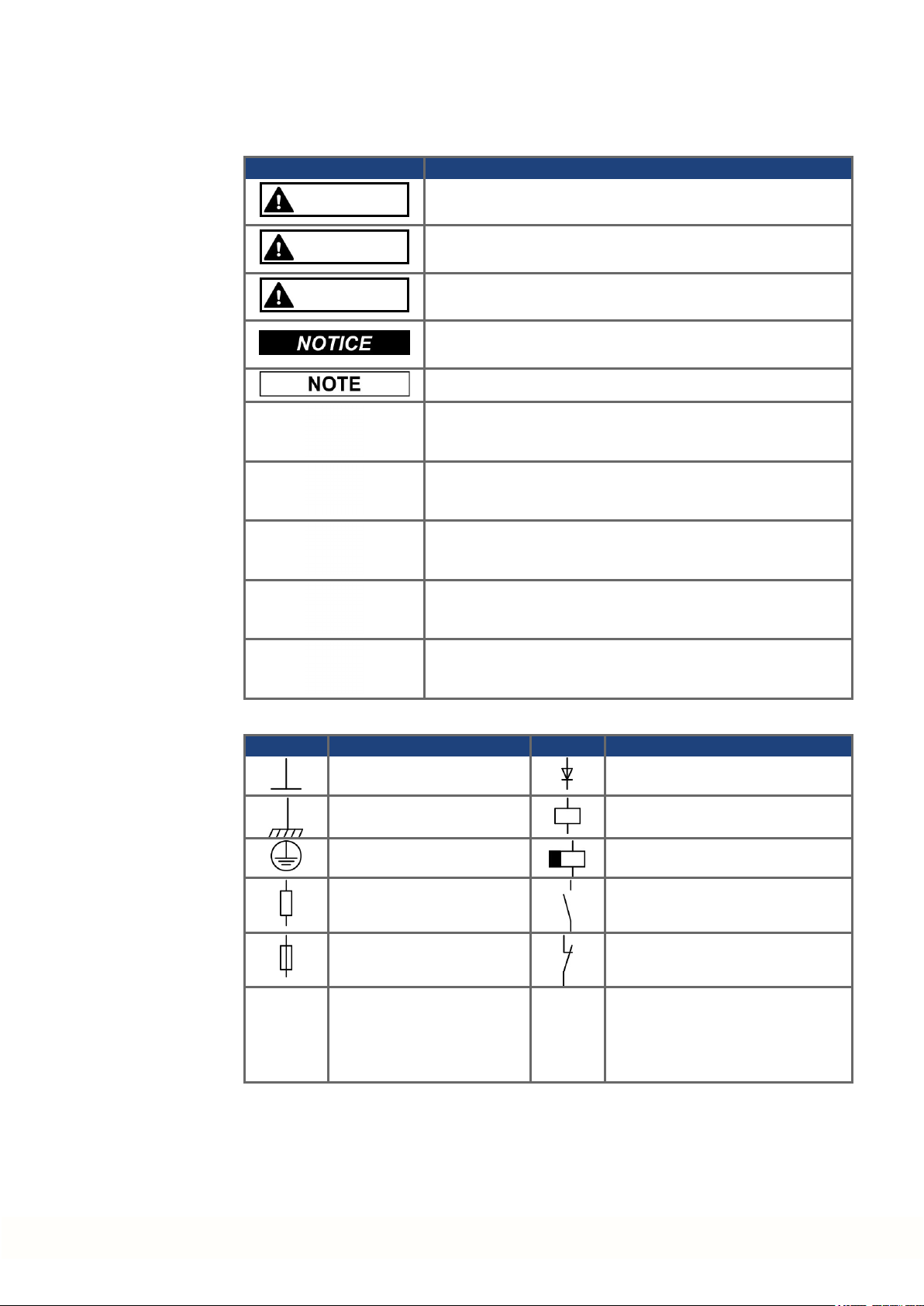
2.4 Symbols Used
Warning Symbols
Symbol Indication
DANGER
Indicates a hazardous situation which, if not avoided, will result
in death or serious injury.
AKD-C Installation | 2 General
WARNING
CAUTION
Indicates a hazardous situation which, if not avoided, could result in death or serious injury.
Indicates a hazardous situation which, if not avoided, could result in minor or moderate injury.
Indicates situations which, if not avoided, could result in property damage.
This symbol indicates important notes.
Warning of a danger (general). The type of danger is specified
by the text next to the symbol.
Warning of danger from electricity and its effects.
Warning of danger from hot surface.
Warning of danger from suspended loads.
Warning of danger from automatic start.
Drawing symbols
Symbol Description Symbol Description
Signal ground Diode
Chassis ground Relay
Protective earth Relay switch off delayed
Resistor Normally open contact
Fuse Normally closed contact
State-of-the-art firewall
Kollmorgen | kdn.kollmorgen.com | February 2018 9
AKD-C Installation | 2 General
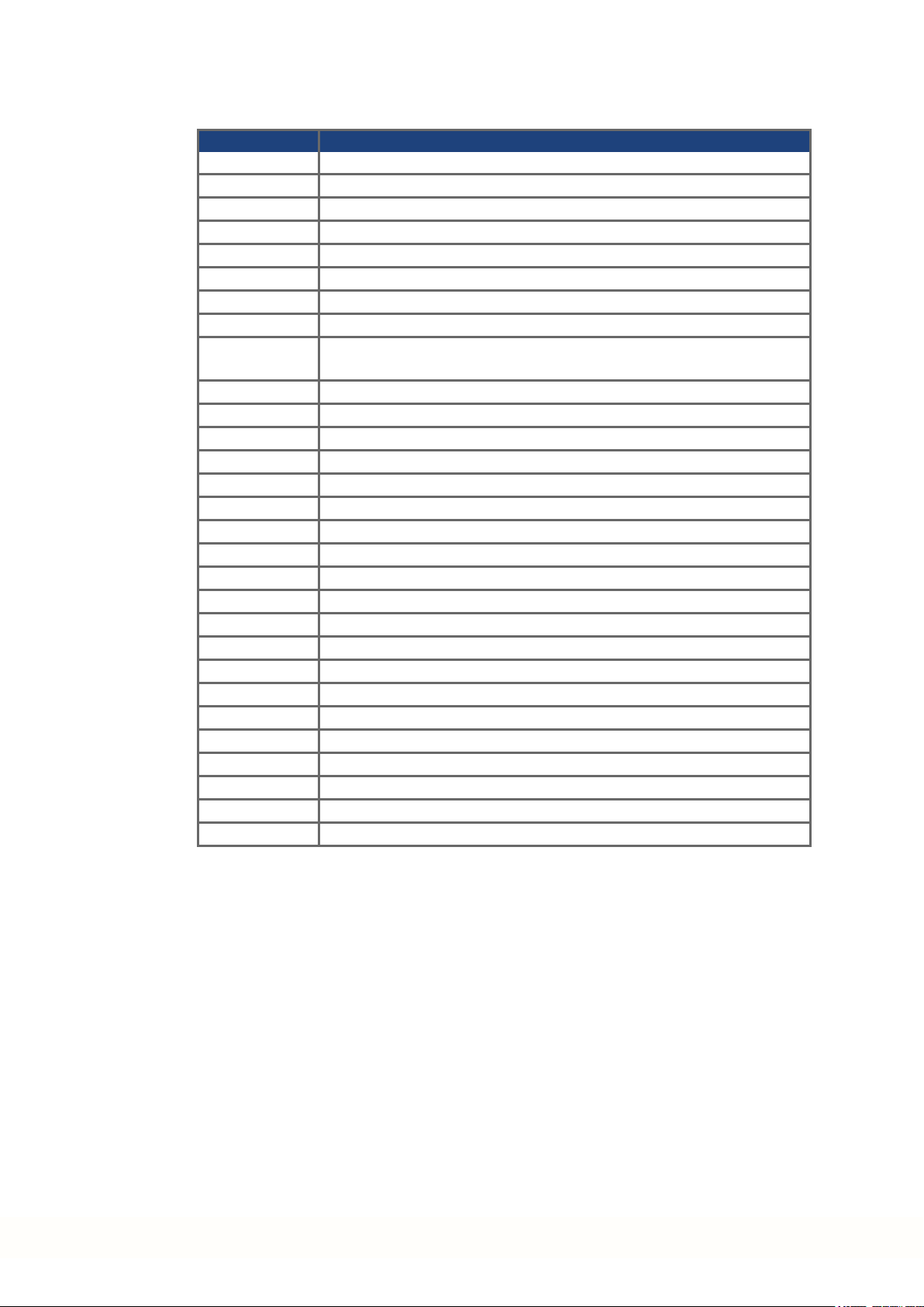
2.5 Abbreviations Used
Abbreviation Meaning
(➜ # 53) "see page 53" in this document
CE Communité Européenne
COM Serial interface for a personal computer
DCOM Communication line for digital inputs
Disk Magnetic storage (diskette, hard disk)
EEPROM Electrically erasable programmable memory
EMC Electromagnetic compatibility
KAS Kollmorgen Automation Suite
KAS IDE Setup software (KollmorgenAutomation Suite Integrated Development
LED Light-emitting diode
LSB Low significant byte (or bit)
MSB Main significant byte (or bit)
NI Zero pulse
OSSD Output signals Switching Device
PC Personal computer
PE Protective earth
PELV Protective extra low voltage
PLC Programmable logic control
PWM Pulse-width modulation
RAM Random access memory (volatile memory)
RBrake/RB Regenresistor (also called a brake resistor)
RBext External regen resistor
RBint Internal regen resistor
RCD Residual current device
RES Resolver
ROD Incremental encoder (A quad B)
STO Safe torque off
VAC Volts, alternating current
VDC Volts, direct current
Environment)
10 Kollmorgen | kdn.kollmorgen.com | February 2018
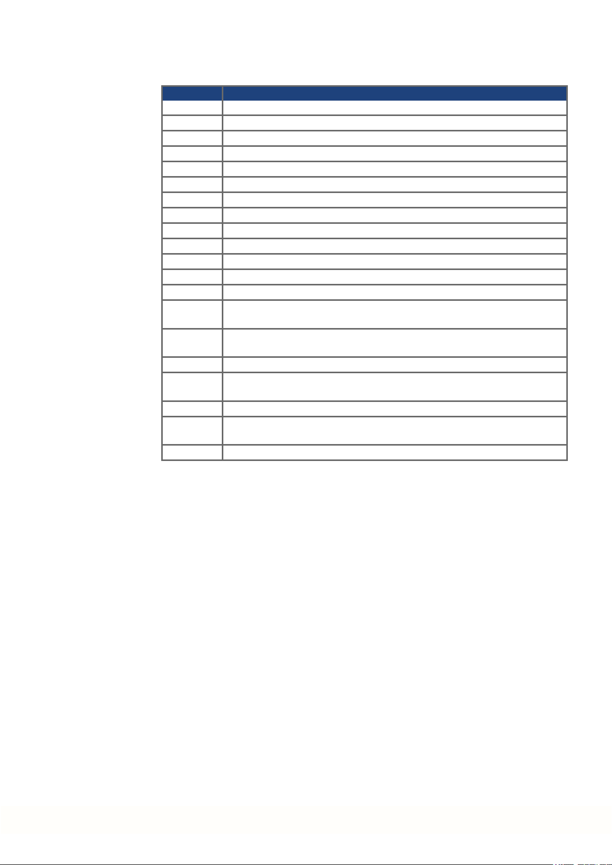
2.6 Standards Used
Standard Content
ISO 4762 Hexagon socket head cap screws
ISO 11898 Road vehicles — Controller area network (CAN)
ISO 12100 Safety of machinery: Basic concepts, general principles for design
ISO 13849 Safety of machinery: Safety-related parts of control systems
IEC 60085 Electrical insulation - Thermal evaluation and designation Maintenance
IEC 60204 Safety of Machinery: Electrical equipment of machinery
IEC 60364 Low-voltage electrical installations
IEC 60439 Low-Voltage Switchgear and Controlgear Assemblies
IEC 60529 International protection rating (IP code)
IEC 60664 Insulation coordination for equipment within low-voltage systems
IEC 60721 Classification of environmental conditions
IEC 61000 Electromagnetic compatibility (EMC)
IEC 61131 Programmable controllers
IEC 61491 Electrical equipment of industrial machines – Serial data link for real-time com-
IEC 61508 Functional safety of electrical/electronic/programmable electronic safety-
IEC 61800 Adjustable speed electrical power drive systems
IEC 62061 Functional safety of electrical/electronic/programmable electronic safety-
IEC 82079 Preparation of instructions for use - Structuring, content and presentation
UL 840 UL Standard for Safety for Insulation Coordination Including Clearances and
UL 508C UL Standard for Safety Power Conversion Equipment
AKD-C Installation | 2 General
munications between controls and drives.
related systems
related systems
Creepage Distances for Electrical Equipment
ANSI - American National StandardInstitute, Inc.
IEC - International Electrotechnical Commission
ISO - International Organization forStandardization
UL - Underwriters Laboratories
Kollmorgen | kdn.kollmorgen.com | February 2018 11

AKD-C Installation | 3 Safety
3 Safety
3.1 You should pay attention to this 13
3.2 Use as Directed 15
3.3 Prohibited Use 16
3.4 Warning notes placed on the product 16
12 Kollmorgen | kdn.kollmorgen.com | February 2018

3.1 You should pay attention to this
This section helps you to recognize and avoid dangers to people and objects.
Specialist staff required!
Only properly qualified personnel are permitted to perform such tasks as transport,
assembly, setup and maintenance. Qualified specialist staff are persons who are familiar
with the transport, installation, assembly, commissioningand operation of drive technology
andwho bring their relevant minimum qualifications to bear on their duties:
Transport: only by personnel with knowledge of handling electrostatically sensitive components.
Unpacking: only by electrically qualified personnel.
Installation: only by electrically qualified personnel.
Basic tests / Setup: only by qualified personnel with knowledge of electrical engineering
anddrive technology
The qualified personnel must know and observe ISO 12100 / IEC 60364 / IEC 60664 and
national accident prevention regulations.
Read the documentation!
Read the available documentationbefore installation and commissioning. Improper handling
of the device can cause harm to people ordamage to property. The operatorof systems
using the AKD-C must ensure that all personnel who work with the system read and understand the manual before using the device.
AKD-C Installation | 3 Safety
Check Hardware Revision!
Check the Hardware Revision Number of the product (see product label). This number is the
link between your product and the manual. The product Hardware Revision Numbermust
match the Hardware Revision Number on the cover page of the manual.
Pay attention to the technical data!
Adhere to the technical data and the specifications on connection conditions. If permissible
voltage values or current values are exceeded, the devices can be damaged. Unsuitable
motor or wrong wiring will damage the system components. Check the combination of drive
andmotor. Compare the rated voltage and current of the units.
Perform a risk assessment!
The manufacturer of the machine must generate a risk assessment for the machine, and take
appropriate measures to ensure that unforeseen movements cannot cause injury or damage
to any person or property. Additional requirements on specialist staff may also result from the
risk assessment.
Automatic Restart!
The drive might restart automatically after power on, voltagedip or interruption of the supply
voltage, depending on the parameter setting.
Risk of death or serious injury for humans working in the machine.
If the parameter DRV.ENDEFAULT for one AKD-N is set to 1, then place a warning sign to
the machine (Warning: Automatic Restart at Power On) and ensure, that power on is not possible, while humans are in a dangerous zone of the machine. In case of using an undervoltage protection device, you must observe EN 60204-1:2006 chapter 7.5 .
Kollmorgen | kdn.kollmorgen.com | February 2018 13

AKD-C Installation | 3 Safety
Observe electrostatically sensitive components!
The devices containelectrostatically sensitive components which may be damaged by incorrect handling. Electrostatically discharge your body before touching the device. Avoid contact with highly insulating materials (artificial fabrics, plastic film etc.). Place the device on a
conductive surface.
Earthing!
It is vital that you ensure that the device is safely earthed to the PE (protective earth) busbar
in the switch cabinet. Risk of electric shock. Without low-resistance earthing no personal protection can be guaranteed.
Leakage Current!
Since the leakage current to PE is more than 3.5 mA, in compliance with IEC61800-5-1 the
PE connection must either be doubled or a connecting cable with a cross-section >10 mm²
must be used. Deviating measures according to regional standards might be possible.
Residual current protective or monitoring devices!
AKD-C with AKD-N can cause a d.c. current in the protective earthing conductor. Where a
residual current-operated protective (RCD) or monitoring (RCM) device is used for protection
in case of direct or indirect contact, only an RCD or RCM of Type B is allowed on the supply
side of AKD-C.
Lethal voltages!
The equipment produces high electric voltages up to 900V. Do not open or touch the equipment duringoperation. Keep all covers closed.
Duringoperation, AKD-C may have uncovered live sections, according to their level of
enclosure protection.
Lethal danger exists at live parts of the device. Built-in protection measures such as insulation orshielding may not be removed. Work on the electrical installation may only be performed by trained and qualified personnel, in compliance with the regulations for safety at
work, and only with switched off mains supply, and secured against restart.
Never undo any electrical connections to the AKD-C while it is live. There is a danger of electrical arcing with damage to contacts and personal injury. Wait at least 7 minutes after disconnecting the product from the supply voltages (mains supply and 24V supply) before
touching potentially live sections of the equipment (such as contacts) or removing any connections.
Always measure the voltage in the DC bus link at connector X14 and wait until the voltage is
below 50 V before handling components.
Functional Safety
The STO safety implementation on the AKD is certified. The safety circuit implementation
used for the safety function "Safe Torque Off" in the drive is suited for SIL 2 accordingto IEC
62061 and PLd/ CAT3 according to ISO 13849-1. The assessment of the safety functions
according to EN13849 or EN 62061 must finally be done by the user.
Never modify the product!
It is not allowed to modify the product without permission by the manufacturer. Opening the
housing causes loss of warranty.
14 Kollmorgen | kdn.kollmorgen.com | February 2018

3.2 Use as Directed
The AKD-C series power supplies are exclusively intendedfor operating AKD-N series
drives within a decentralized drive system.
AKD-C are components that arebuilt into electrical plants or machines and can only be operated as integral components of these plants or machines. The manufacturer of the machine
must generate a risk assessment for the machine.
When the devices are built into machines or plant, the drive must not be used until it has been
established that the machine or plant fulfills the requirements of the regional directives.
Kollmorgen Decentral drive system
AKD-C series power supply must only be operated in a motion system with components
from Kollmorgen. Required additional Kollmorgen components are the "near servo drives"
AKD-N, hybrid cables, motor power and feedback cables, servomotors.
Assembling
AKD-C devices must only be operated in environments suitable for the ambient conditions
defined on (➜ # 31). Observe the information givenin the Decentralized System Projecting
Guide.
Wiring
Use only Kollmorgen CCNxN1 series of hybrid cables for connecting AKD-N and AKD-C
devices.
AKD-C Installation | 3 Safety
Power supply
AKD-C must be powered from a 3 phase industrial supply network
(not more than 42 kA symmetrical rated current at 400 V and 480 V).
For the cases of group installations and of DC powered drives
AKD has not been evaluated by Kollmorgen, UL, or TÜV for group installations nor are ratings defined for DC input voltage.
Group installations must be reviewed and evaluated by the user for branch circuit protection*,
wire size, wire voltage rating, fuse protection, system dielectric requirements, overvoltage
andinput** current rating.
In case of DC supplied drives the built-in EMC filter will not work. The user is responsible to
keep the conducted emissions and the immunity of the drive within the required noise levels.
* Special care must be taken in branch circuit design with mixed rating drives to avoid the
smaller drives becoming the effective ‘fuse’ rather than the circuit protective fuse.
** The power supply system design must ensure inrush current protection by limiting input
current during power up. DC supply polarity must be properly wired. Improper polarity of DC
powerwill damage the drive and void warranty.
Auxiliary voltage supply, Standby power
Standby power for the drive strings must only be used for supplying the AKD-N electronics.
24 VDC supply unit must accord to PELV (EN 60204-1) requirements.
Safe torque off
Review the section "Use as Directed" in the STO chapter(➜ # 38) beforeusing this safety
function (SIL2, PLd, category 3 according to ISO 13849).
24 VDC supply unit for global STO supply must accord to PELV (EN 60204-1) requirements.
Kollmorgen | kdn.kollmorgen.com | February 2018 15
AKD-C Installation | 3 Safety
3.3 Prohibited Use
Otheruse than that described in chapter “Use as directed”is not intended and can lead to personnel injuries and equipment damage.
The device may not be used
with a machine that does not comply with appropriate national directives or standards,
for driving elevators,
in applications with continuous, operational short circuits to the external regen resistor
contacts.
in applications with any short circuits to the DC-Bus link contacts.
The use of the device in the following environments is also prohibited:
potentially explosive areas
environments with corrosive and/or electrically conductive acids, alkaline solutions, oils,
vapors, dusts
ships or offshoreapplications
Wiring the system with hybrid cables from other manufacturers than Kollmorgen is not
allowed. Changing Kollmorgen cables or connectors is not allowed.
3.4 Warning notes placed on the product
Wait 7 minutes
after removing power
before servicing.
If these signs are damaged, they must be replaced immediately.
The minimum size of the protective earth
conductor shall comply with the local safety
regulations for high protective earthing
conductor current.
16 Kollmorgen | kdn.kollmorgen.com | February 2018

AKD-C Installation | 4 Handling
4 Handling
4.1 Packaging 18
4.2 Transport 18
4.3 Storage 18
4.4 Decommissioning 18
4.5 Maintenance and cleaning 19
4.6 Disassemble 19
4.7 System Repair 19
4.8 Disposal 20
Kollmorgen | kdn.kollmorgen.com | February 2018 17
AKD-C Installation | 4 Handling
4.1 Packaging
The AKD-C packaging consists of recyclable cardboard with inserts and a label onthe outside of the box.
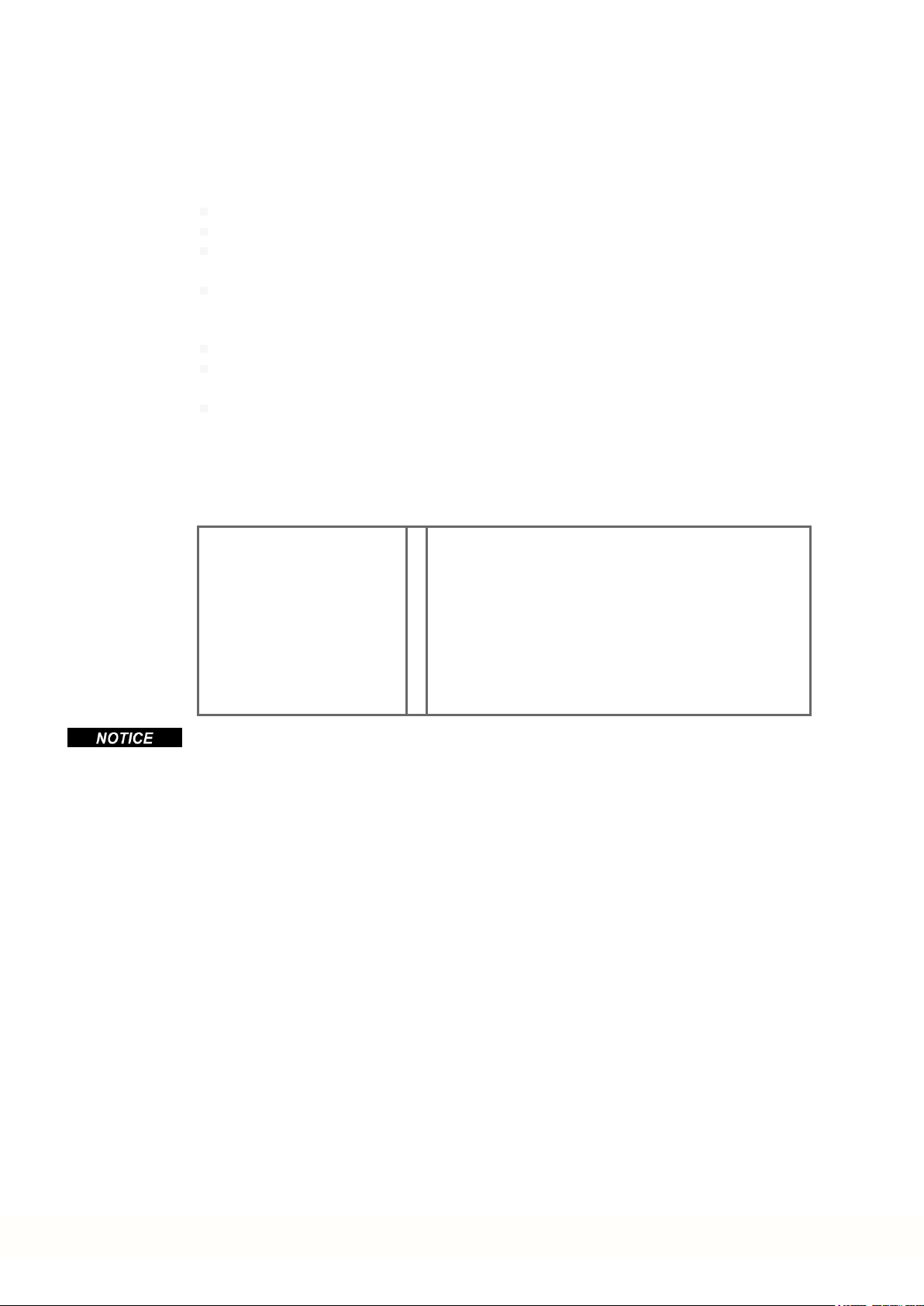
4.2 Transport
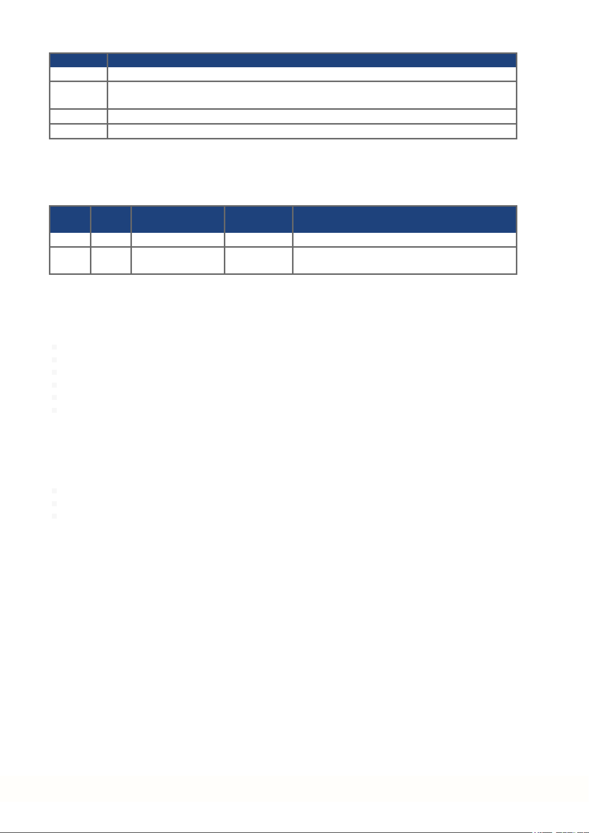
Model Package Dimensions
(mm) HxWxL
AKD-C01007 125x 410 x 295 5
Transport the AKD-C in accordance with IEC 61800-2 as follows:
Transport only by qualified personnel in the manufacturer’s original recyclable packaging.
Avoid shocks while transporting.
Store at or below maximum stacking height of 8 cartons
Transport only within specified temperature ranges: -25 to +70 °C, max. rate of change 20
K/hour, class 2K3.
Transport only within specified humidity: maximum 95% relative humidity, no condensation, class 2K3.
The devices containelectrostatically sensitive components that can be damaged by incorrect handling. Electrostatically discharge yourself before touching the device. Avoid contact
with highly insulating materials, such as artificial fabrics and plastic films. Place the device
on a conductive surface.
If the packaging is damaged, check the unit for visible damage. Inform the shipper and the
manufacturer of any damage to the package or product.
Total Weight
(kg)
4.3 Storage
Store the AKD-C in accordance with IEC 61800-2 as follows:
Store only in the manufacturer’s original recyclable packaging.
Store at or below maximum stacking height of 8 cartons
Store only within specified temperature ranges: -25to +55 °C, max.rate of change 20
K/hour, class 1K4.
Storage only within specified humidity: 5 to 95% relative humidity, no condensation, class
1K3.
Store in accordance with the following duration requirements:
Less than 1 year: without restriction.
More than 1 year: capacitors must be re-formed before setting up andoperating the
drive. Re-forming procedures are described in the Kollmorgen DeveloperNetwork
(Forming).
4.4 Decommissioning
Only professional staff who are qualified in electrical engineering are allowed to decommission parts of the system.
DANGER: Lethal Voltages!
There is a danger of serious personal injury or death by electrical shock or electrical arcing.
Switch off the main switch of the switchgear cabinet.
Secure the system against restarting.
Block the main switch.
Wait at least 7 minutes after disconnecting.
18 Kollmorgen | kdn.kollmorgen.com | February 2018

4.5 Maintenance and cleaning
The device does not require maintenance. Opening the device voids the warranty. The inside
of the unit can only be cleaned by the manufacturer.
Do not immerse orspray the device. Avoid that liquid enters the device.
To clean the device exterior:
1. Decommission the device (see chapter 4.4 "Decommissioning").
2. Casing: Clean with isopropanol or similar cleaning solution.
Caution : Highly Flammable! Risk of injury by explosion and fire.
Observe the safety notes given on the cleaning liquid package.
Wait at least 30 minutes after cleaningbefore putting the device back into operation.
3. Protective grill on fan: Clean with a dry brush.
4.6 Disassemble
Only professional staff who are qualified in electrical engineering are allowed to disassemble
parts of the system.
AKD-C Installation | 4 Handling
1. Decommission the device (see chapter 4.4 "Decommissioning").
2. Remove the connectors. Disconnect the potential earth connection last.
3. Demount: loosen the fastening screws. Remove the device.
4.7 System Repair
Only professional staff who are qualified in electrical engineering are allowed to exchange
parts of the drive system.
CAUTION: Automatic Start! During replacement work a combination of hazards and mul-
tiple episodes may occur.
Exchange of AKD-C
Only the manufacturer can repair the device. Opening the device voids the warranty.
1. Decommission the device (see chapter 4.4 "Decommissioning").
2. Demount the device (see chapter 4.6 "Disassemble").
3. Send the device to the manufacturer.
4. Install a new device as described in this manual.
5. Setup the system as described in this manual.
Work on the electrical installationmay only be performed by trained and qualified personnel, in compliance with the regulations for safety at work, and only with use of prescribed personal safety equipment.
Exchange of other drive system parts
If parts of the drive system (for example cables) must be replaced, proceed as follows:
1. Decommission the device (see chapter 4.4 "Decommissioning").
2. Exchangethe parts.
3. Check all connections for correct fastening.
4. Setup the system as described in this manual.
Kollmorgen | kdn.kollmorgen.com | February 2018 19
AKD-C Installation | 4 Handling
4.8 Disposal
To dispose the unit properly, contact a certified electronic scrap disposal merchant.
In accordance with the WEEE-2002/96/EC-Guidelines and similar, the manufacturer accepts
returns of old devices andaccessories for professional disposal. Transport costs are the
responsibility of the sender.
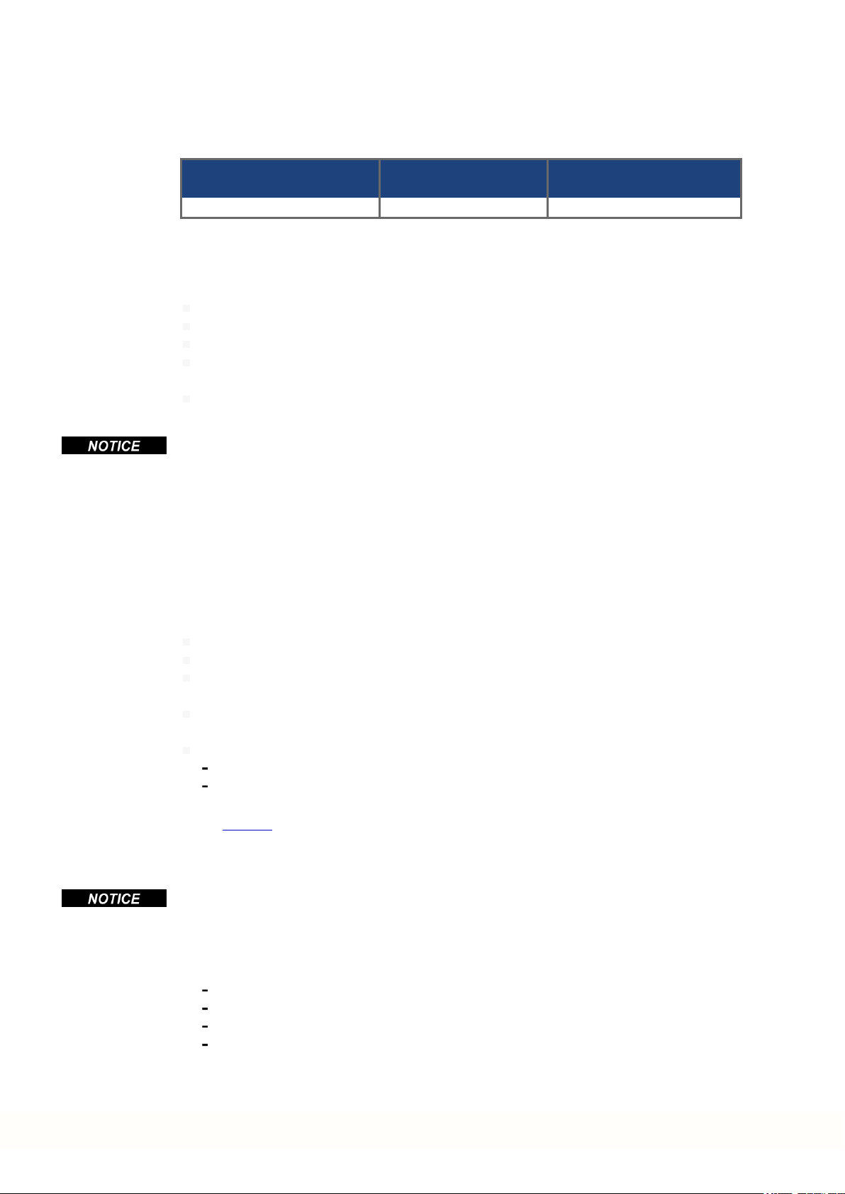
Send the devices in the original packaging to the manufacturer address:
North America South America
KOLLMORGEN
201West Rock Road
Radford, VA 24141, USA
Europe Asia
KOLLMORGEN Europe GmbH
Pempelfurtstr. 1
40880 Ratingen, Germany
KOLLMORGEN
Avenida Tamboré - 1077 Tamboré
Barueri - SP Brasil
CEP:06460-000, Brazil
KOLLMORGEN
Floor 4, Building 9, No. 518,
North Fuquan Road, Changning District,
Shanghai 200335, China
20 Kollmorgen | kdn.kollmorgen.com | February 2018

AKD-C Installation | 5 Approvals
5 Approvals
5.1 Conformance with UL/cUL 22
5.2 Conformance with EC Low Voltage and EMC Directives 23
5.3 Conformance with EC Machinery Directive, Functional Safety 23
5.4 Conformance with EAC 24
5.5 Conformance with RoHS 24
5.6 Conformance with REACH 24
Kollmorgen | kdn.kollmorgen.com | February 2018 21
AKD-C Installation | 5 Approvals
5.1 Conformance with UL/cUL
This device is listed under UL (Underwriters Laboratories Inc.) file number E217428. UL Markings are combined
for both AKD-C and AKD-N in one section.
5.1.1 UL Markings / Marquages UL
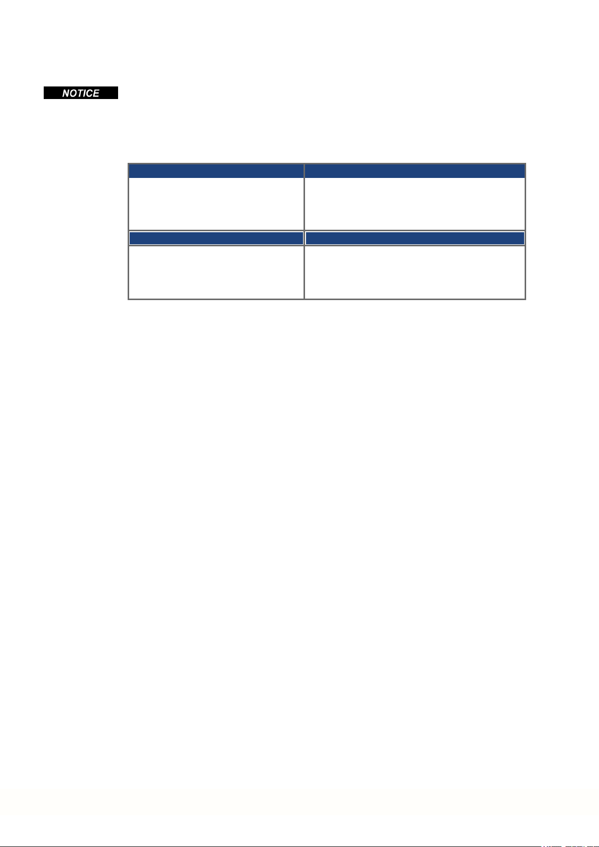
English Français
This product is suitable for use on a circuit capable of delivering not more than 42,000 rms symmetrical amperes, 480 V maximum.
Maximum surrounding airtemperature 40°C. La température maximale de l'air ambiant de 40°C.
AKD-C are intended to beused in a pollution
degree 2 environment.
AKD-C : Use 60/75°C copperwire only. AKD-C: Utilisez seulement un fil cuivre 60/75°C.
AKD-C :CAUTION Risk of Electrical Shock!
Capacitors can have dangerous voltages present
up to 7 minutes after switching off the supply
power. For increased safety, measurethe
voltage in the DC bus link and wait until the
voltage is below 50 V.
For use in Canada:
Transient surge suppression shall be installed on
the line side of this equipment and shall be rated
277V (phase to ground), 480 V (phase to phase),
suitable for overvoltage category III, and shall
provide protection for a rated impulse withstand
voltage peak of 2 kV.
Ce produit est conçu pour une utilisation sur un circuit
capable de fournir 42.000 ampères symétriques (rms)
maximum pour 480 V maximum.
AKD-C sont prévus pour une utilisation dans un
environnement de pollution de niveau 2.
AKD-C :ATTENTION: Risque de choc électrique!
Des tensions dangereuses peuvent persister dans les
condensateurs jusqu'à 7 minutes après la mise hors
tension. Pour plus de sécurité, mesurez la tension
dans la liaison de bus CC et attendez qu'elle soit
inférieure à 50 V.
Pour utilisation au Canada:
Suppression de surtension transitoire doit être installé
sur le côté de la ligne de ce matériel et doit être évalué
277 V (phase à terre) , 480 V (entre phases) , adapté à
la catégorie de surtension III , et doit fournir une protection pour un choc nominale supporter la tension de
crête de 2 kV.
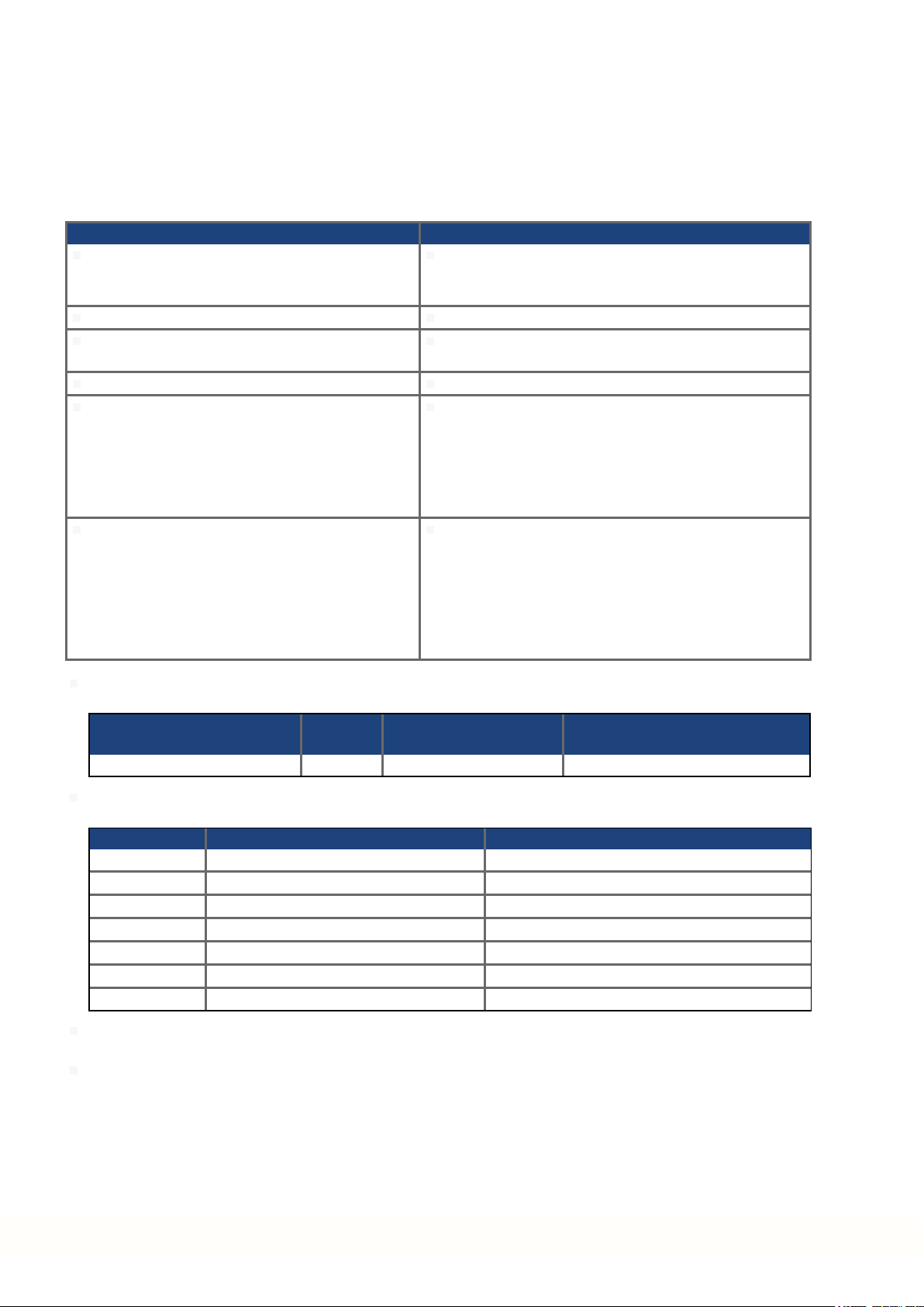
The following fuse types are recommended for branch circuit protection for AKD-C01007-CBXX:
Les types de fusibles suivants sont recommandés pour protection de secteur pour AKD-C01007-CBXX:
Model/
Modèle
Nonrenewable Cartridge fuse CC, J 600 VAC 20 A, 200 kA
The following table illustrates the torque requirements for the field wiring connectors :
Le tableau suivant indique les spécifications de couple pour les connecteurs de câblage sur site:
Model/Modèle Torque/Couple serrage, LBIN (Nm) Wire size/Section de fil, AWG (mm²)
AKD-C X12 6.2 - 7.1 (0.7 - 0.8) 12 - 8 (4- 10)
AKD-C X20A 6.2 - 7.1 (0.7 - 0.8) 12 - 8 (4 - 10)
AKD-C X21A 6.2 - 7.1 (0.7 - 0.8) 12 - 8 (4 - 10)
AKD-C X14 6.2 - 7.1 (0.7 - 0.8) 12 - 8 (4- 10)
AKD-C X13 1.8 - 2.2 (0.2 - 0.25) 14 - 12(2.5 - 4)
AKD-C X15 1.8 - 2.2 (0.2 - 0.25) 20 - 18(0.5 - 0.8)
AKD-C X16 1.8 - 2.2 (0.2 - 0.25) 20 - 18(0.5 - 0.8)
Split gage of AKD-N screwed connectors: max. 2.8 mm.
Le gage de split des connecteurs vissé d'AKD-N: 2,8 mm max.
Cold plate for AKD-N: at 40°C surrounding air temperature and 680 VDC supply voltage:
Plaque froide pour AKD-N: à température ambiante 40°C et tension d'alimentation 680 VDC:
- AKD-N00307: 240 mm x 240 mm x 10 mm or equivalent (LxWxT, Aluminum cold plate, uncoated)
- AKD-N00607: 500 mm x 500 mm x 10 mm or equivalent (LxWxT, Aluminum cold plate, uncoated)
- AKD-N01207: 480 mm x 400 mm x 84 mm or equivalent (LxWxT, 31 vertical fins, Aluminum heat sink,
uncoated)
Class/
Classe
Voltage Rating/
Niveau de tension
Max. Fuse&SCC Rating/
Niveau maximum & SCC
22 Kollmorgen | kdn.kollmorgen.com | February 2018
5.2 Conformance with EC Low Voltage and EMC Directives
EU Declarations of Conformity can be found on the Kollmorgen website.
Conformance with the EC EMC Directive 2014/30/EC and the Low Voltage Directive
2014/35/EC is mandatory for the supply of drives within the European Community.
The devices have been tested by an authorized testing laboratory in a defined configuration,
using the system components that are described in this documentation. Any divergence from
the configuration andinstallation described in this documentation means that the user will be
responsible for carrying out new measurements to ensure conformance with regulatory
requirements.
Kollmorgen declares the conformity of the product series AKD-C01007 with the following directives:
EC Directive 2006/42/EC, Machinery Directive
Used harmonized standard EN13849-1 (2008)
EC Directive 2014/35/EC, Low Voltage Directive
Used harmonized standard EN61800-5-1 (2007)
EC Directive 2014/30/EC, EMC Directive
Used harmonized standard EN 61800-3 (2004)
The AKD-C01007 meet the noise immunity requirements to the 2nd environmental category
(industrial environment). For noise emission the AKD-C01007 meet the requirement to a
product of the Category C2.
AKD-C Installation | 5 Approvals
These devices can cause high-frequency interferences in non industrial environments and
may requiremeasures for interference suppression (such as additional external EMC filters).
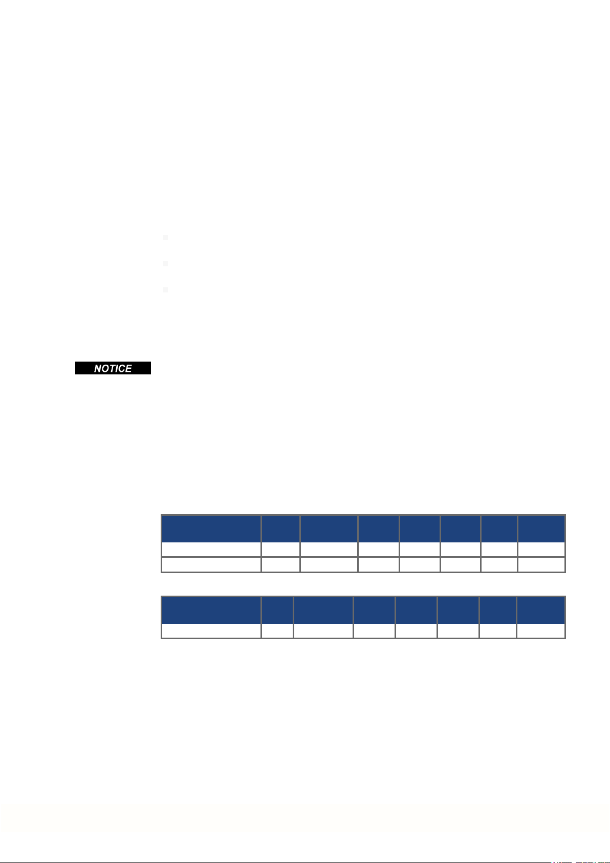
5.3 Conformance with EC Machinery Directive, Functional Safety
Conformance with the EC Machinery Directive 2006/42/EC is mandatory for the supply of
safety components within the European Community. The STO safety implementationon the
AKD-N is certified by TÜV. The safety circuit implementation used for thesafety function
"Safe Torque Off" in the drives is suited for SIL 2 according to IEC 62061 and PLd / CAT3
according to ISO 13849-1.
Safe Torque Off (STO) string type (global)
Structure STO ISO
13849-1
AKD-C + 1 x AKD-N global PL d, CAT 3 ≥ 100 SIL 2 2.9E-08 97.08 20
AKD-C + 8 x AKD-N global PL d, CAT 3 ≥ 100 SIL 2 2.9E-08 99.44 20
Safe Torque Off (STO) single drive type (local)
Structure STO ISO
13849-1
1 x AKD-N-DS/DT local PL d, CAT 3 ≥ 100 SIL 2 2.9E-08 97.12 20
See AKD-N Installation Manual for detailed information.
MTTF
MTTF
d
d
IEC
62061
IEC
62061
PFH
[1/h]
PFH
[1/h]
SFF
[%]
SFF
[%]
T
M
[Years]
T
M
[Years]
Kollmorgen | kdn.kollmorgen.com | February 2018 23

AKD-C Installation | 5 Approvals
5.4 Conformance with EAC
EAC is the abbreviation for Eurasian Conformity. The mark is used in the states of the Eurasian Customs Union (Russia, Belarus, Kazakhstan) similar to the European CE mark.
Kollmorgen declares, that the AKD has passed all requiredconformity procedures in a memberstate of the Eurasian Customs Union, and that the AKD meets all technical requirements
requested in the member states of the Eurasian Customs Union:
Low voltage (TP TC 020/2011)
Electromagnetic Compatibility (TP TC 004/2011)
Contact: Intelisys LLC. , Bakuninskaya Str. d 14, Building 10, RU-105005 Moskau
5.5 Conformance with RoHS
Directive 2011/65/EC of the European Union on the restriction of the use of certain hazardous substances in electrical and electronic equipment (RoHS) becameoperative as from
the 3rd of January, 2013. Following substances namely are involved
Lead (Pb), Cadmium (Cd), Hexavalent chromium (CrVI), Polybrominated biphenyls (PBB),
Polybrominated diphenyl ethers (PBDE), Mercury (Hg)
The AKD is manufactured in conformance with RoHS.
5.6 Conformance with REACH
EU Regulation no. 1907/2006 deals with the registration, evaluation, authorization and restriction of chemical substances 1 (abbreviated to "REACH").
AKD does not contain any substances (CMR substances, PBTsubstances, vPvB substances and similar hazardous substances stipulatedin individual cases based on scientific
criteria) above 0.1 mass percent per product that are included onthe candidate list.
24 Kollmorgen | kdn.kollmorgen.com | February 2018

AKD-C Installation | 6 Package
6 Package
6.1 Package Supplied 26
6.2 Nameplate 26
6.3 Part Number Scheme 27
Kollmorgen | kdn.kollmorgen.com | February 2018 25

AKD-C Installation | 6 Package
6.1 Package Supplied
When a device from the AKD-C series is ordered,, the following items are included in the
package:
AKD-C
Printed copy of AKD-C Installation Manual
DVD containing the setup software, WorkBench, and all product documentation in digital
format.
Mating connectors X12, X13, X14, X15, X16
Two connector covers M23
The M23 connector covers are required for protecting X2 of the last AKD-N in the strings.
Accessories Sold Separately
Accessories must be ordered separately if required; refer to your regional accessories
manual:
Hybrid cables for connection to first AKD-N
External regen resistor
EtherCAT cable to the network
Power cable, control wires
Cabinet grommets
Slip rings
6.2 Nameplate
Spare parts
Spare parts are described in the regional accessories manual:
Connector Kit (X12...16)
Shield clamp SK14
The nameplate depicted below is attachedto the side of the device. Picture similar to the
nameplate on the device.
26 Kollmorgen | kdn.kollmorgen.com | February 2018

6.3 Part Number Scheme
Use the part number scheme for product identification only, not for the order process,
because not all combinations of features are possible, always.
AKD-C Installation | 6 Package
Customization code includes language version of printed material and not safety relevant
customer specials.
Kollmorgen | kdn.kollmorgen.com | February 2018 27

AKD-C Installation | 7 Technical description and data
7 Technical description and data
7.1 The AKD-C Central Power Supply 29
7.2 Mechanical Data 30
7.3 Electrical Data 30
7.4 Fusing 31
7.5 Ambient Conditions, Ventilation, and Mounting Position 31
7.6 Grounding System 32
7.7 Signal Inputs/Outputs 32
7.8 Connectors 33
7.9 Recommended Tightening Torques 33
7.10 Cable Requirements 33
7.11 Cable Length Definition 34
7.12 Dynamic Braking 35
7.13 Regen circuit 35
7.14 Switch-On and Switch-Off Behavior 36
7.15 Global Safe Torque Off (STO) 38
7.16 Shock-hazard Protection 46
7.17 LED Display 46
28 Kollmorgen | kdn.kollmorgen.com | February 2018
 Loading...