

Page 1
AKD
®
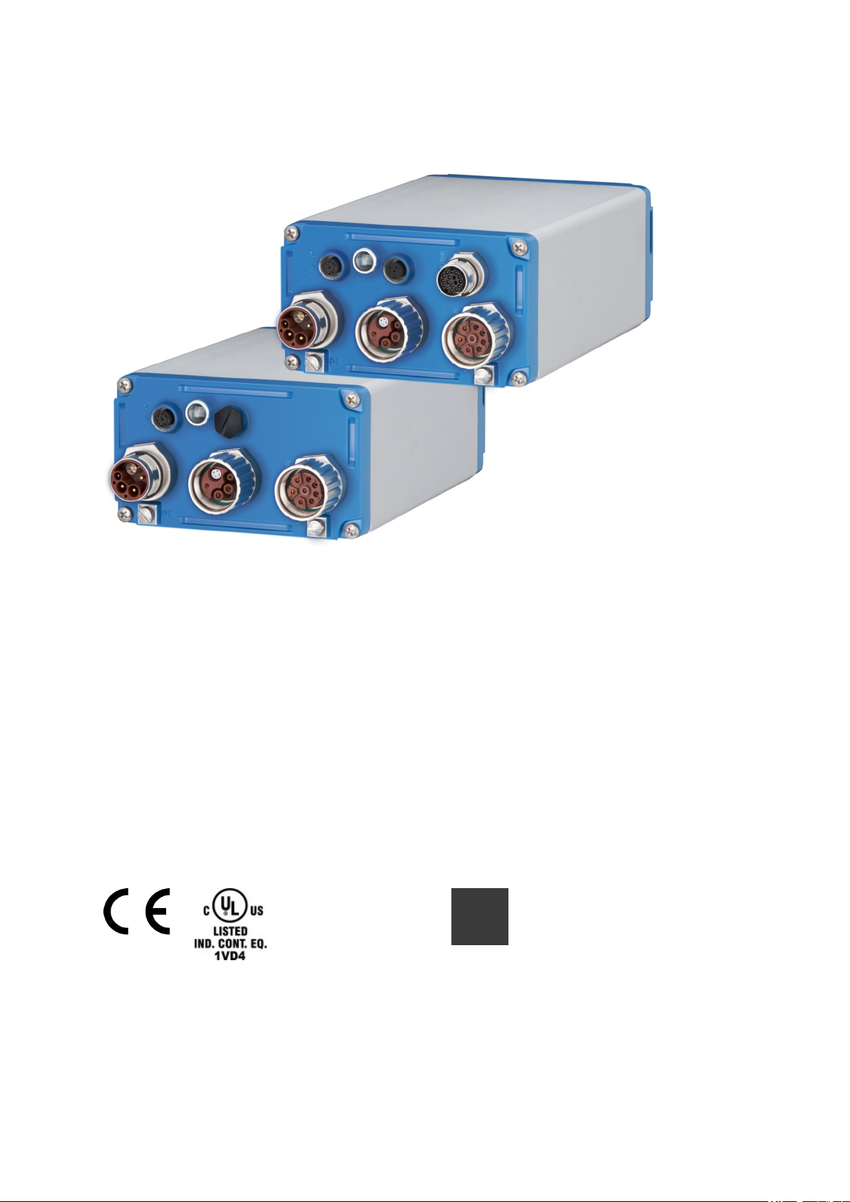
Near Servo Drive
Installation Manual
Edition: J, February 2018
Valid for AKD-N, Hardware Revision B
Part Number 903-200018-00
Original Document
Keep allmanuals as a product component during the life span of the product. Passallmanuals to
future users and owners of the product.
Page 2
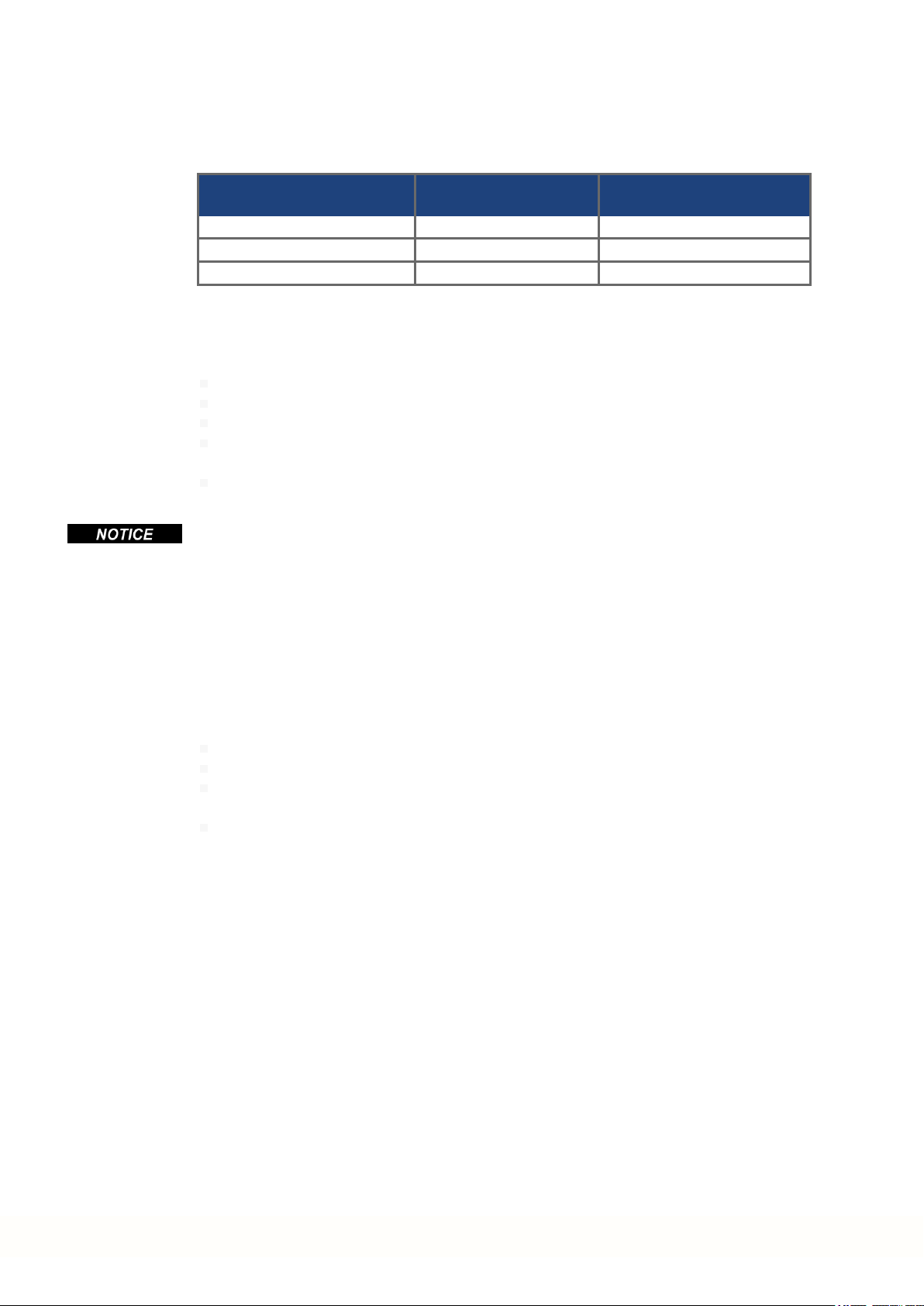
Record of document revisions
Revision Remarks
...
Table with lifecycle information of this document see (➜ # 81)
G, 03/2017 References to cable connector option A3 removed, tertiary fieldbus cable type updated
H, 10/2017 Global STO note, enclosure/wiring note, product prohibited use: elevator
J, 02/2018 Heat sink 40 mm removed, Trademark list updated, SpeedTec spelling corrected
Hardware Revision (HR)
AKD-N AKD-C
Firmware/
WorkBench
Export
Classification
Remarks
A A from 1.11 3A225 AKD-C and AKD-N start revisions
B A from 1.13 -
AKD-N Hardware Revision for export classification
tracebility purposes
Trademarks
AKD is a registered trademark of Kollmorgen Corporation
EnDat is a registeredtrademark of Dr. Johannes Heidenhain GmbH
EtherCAT is a registered trademark and patented technology, licensed by Beckhoff Automation GmbH
HIPERFACE is a registered trademark of Max Stegmann GmbH
SpeedTec is a registered trademark of TE Connectivity Ltd.
Windows is a registeredtrademark of Microsoft Corporation
Current patents
US Patent 8.154.228 (Dynamic BrakingFor Electric Motors)
US Patent 8.214.063 (Auto-tune of a Control System Based on Frequency Response)
US Patent 8.566.415 (Safe Torque Off over network wiring)
Patents referring to fieldbus functions are listed in the matching fieldbus manual.
Technical changes which improve the performance of the device may be made without prior notice!
Printedin Germany
This document is the intellectual property of Kollmorgen. All rights reserved. No part of this work may be reproduced in any form (by photocopying, microfilm or any other method)or stored, processed, copied or distributed
by electronic means without the written permission of Kollmorgen.
2 Kollmorgen | kdn.kollmorgen.com | February 2018
Page 3

AKD-N Installation | Table of Contents
1 Table of Contents
1 Table of Contents 3
2 General 7
2.1 About thisManual 8
2.2 Using the PDF Format 8
2.3 Notes for the Printed Edition (paper version) 8
2.4 SymbolsUsed 9
2.5 AbbreviationsUsed 9
3 Safety 10
3.1 You should payattention to this 11
3.2 Use asDirected 13
3.3 Prohibited Use 13
3.4 Warning notes placed on the product 14
4 Handling 15
4.1 Packaging 16
4.2 Transport 16
4.3 Storage 16
4.4 Decommissioning 17
4.5 Maintenance and cleaning 17
4.6 Disassemble 17
4.7 SystemRepair 18
4.8 Disposal 18
5 Approvals 19
5.1 Conformance withUL/cUL 20
5.1.1 UL Markings/ Marquages UL 20
5.2 Conformance withEC Low Voltage and EMC Directives 21
5.3 Conformance withEC Machinery Directive, Functional Safety 21
5.4 Conformance withEAC 22
5.5 Conformance withRoHS 22
5.6 Conformance withREACH 22
6 Package 23
6.1 PackageSupplied 24
6.2 Nameplate 24
6.3 Part Number Scheme 25
7 Technical description and data 26
7.1 The AKD-N Familyof Digital Drives 27
7.2 MechanicalData 28
7.3 Electrical Data 28
7.4 Performance Data 28
7.5 Ambient Conditions, Ventilation, and Mounting Position 29
7.6 Inputs/Outputs 29
7.7 Connectors 30
7.8 Cable Requirements 31
7.9 Cable lengthdefinition 32
7.10 Dynamic Braking 33
7.11 Regen circuit 33
7.11.1 Functional description 33
7.11.2 Technicaldata 33
7.12 LED Codes 34
7.13 Switch-On andSwitch-Off Behavior 35
7.13.1 Switch-on behavior in standard operation 35
Kollmorgen | kdn.kollmorgen.com | February 2018 3
Page 4

AKD-N Installation | Table of Contents
7.13.2 Switch-off behavior 36
7.13.2.1 Switch-off behavior using a digitalinput (controlled stop) 36
7.13.2.2 Switch-off behavior using the DRV.DIS command 37
7.13.2.3 Switch-off behavior using HW Enableinput on AKD-C (uncontrolled stop) 38
7.13.2.4 Switch-off behavior in the event of a fault 39
7.14 Safe Torque Off (STO) 42
7.14.1 GlobalSTO, control via AKD-C 42
7.14.2 LocalSTO, control via digital input on AKD-N-DS/DT 42
7.14.3 Safety characteristicdata 42
7.14.4 Use as directed 43
7.14.5 Prohibited use 43
7.14.6 Response Time 43
7.14.7 Enclosure, wiring 43
7.14.8 LocalSTO safetyinstructions 44
7.14.9 Technicaldata and pinoutlocal STO 45
7.14.10 Functional description local STO 46
7.14.10.1 Signal diagram (sequence) 46
7.14.11 Functional test 47
7.14.11.1 GlobalSTO 47
7.14.11.2 Local STO 47
7.14.11.3 Local STO applicationexample 48
7.14.11.4 OSSD testpulses 48
8 Mechanical Installation 49
8.1 Important Notes 50
8.2 Temperature Management 51
8.3 MechanicalDrawings 52
8.3.1 DimensionsAKD-N, preferred mounting 52
8.3.2 DimensionsAKD-N with optionalheat sink, preferred mounting 53
9 Electrical Installation 54
9.1 Important Notes 55
9.2 Guide to ElectricalInstallation 56
9.3 SystemTopology of a DecentralizedServo System 57
9.3.1 System limits 57
9.3.2 Example 57
9.4 Wiring 58
9.5 Connection Overview 59
9.5.1 Connector assignment AKD-Nzzz07-DB 59
9.5.2 Connector assignment AKD-Nzzz07-DG/DT 59
9.5.3 Connector assignment AKD-Nzzz07-DF/DS 60
9.5.4 Connection diagram AKD-Nzzz07-DB 61
9.5.5 Connection diagram AKD-Nzzz07-DG/DT 62
9.5.6 Connection diagram AKD-Nzzz07-DF/DS 63
9.6 Hybrid Connection (X1, X2) 64
9.7 I/O Connection (X3) 64
9.7.1 DigitalInputs 65
9.7.2 DigitalOutput 66
9.8 Motor Power Connection (X4) 67
9.8.1 Connector X4 AKD-Nzzz07all variants, hybrid, single cable 67
9.8.2 Connector X4 AKD-Nzzz07-DF/DS, dual cables 67
9.9 Motor Brake Connection (X4) 68
9.10 Motor FeedbackConnection (X4, X5) 69
9.10.1 Connector X4 AKD-Nzzz07all variants,hybrid, single cable 69
9.10.2 Connector X5 AKD-Nzzz07-DF/DS, dualcable 70
9.11 OptionalConnector (X6) 71
4 Kollmorgen | kdn.kollmorgen.com | February 2018
Page 5

AKD-N Installation | Table of Contents
9.11.1 Pinout AKD-Nzzz07-DF/DG 71
9.11.2 Pinout AKD-Nzzz07-DS/DT 71
10 Setup 72
10.1 Important Notes 73
10.2 Setup software WorkBench 74
10.3 InitialSystem Test 75
10.3.1 Unpacking,mounting, and wiring 75
10.3.2 Set IP address 75
10.3.3 Confirm connections 75
10.3.4 Installand start WorkBench 76
10.3.5 Enable the drive using the setup wizard 76
10.4 Fault and Warning Messages 77
11 Index 79
12 Record of document revisions 81
Kollmorgen | kdn.kollmorgen.com | February 2018 5
Page 6

AKD-N Installation |
---/ ---
6 Kollmorgen | kdn.kollmorgen.com | February 2018
Page 7

AKD-N Installation | 2 General
2 General
2.1 About this Manual 8
2.2 Using the PDF Format 8
2.3 Notes for the Printed Edition (paper version) 8
2.4 Symbols Used 9
2.5 Abbreviations Used 9
Kollmorgen | kdn.kollmorgen.com | February 2018 7
Page 8
AKD-N Installation | 2 General
2.1 About this Manual
This manual, AKD-N Installation Manual ("Instructions Manual" accordingto EC Machinery
Directive 2006/42/EC), describes the AKD-N series of digital drives and includes information
needed to safely install an AKD-N. A digital version of this manual (pdf format) is available on
the DVD included with yourdrive. Manual updates can be downloadedfrom the Kollmorgen
website (www.kollmorgen.com).
Additional documents includethe following:
Projecting Guide Decentralized Drive System: describes how to build a decentralized
drive system with AKD-C and AKD-N. It provides tips for system topology, cooling, and
maximizing the system performance.
AKD-C Installation Manual: describes the AKD-C series of intelligent powersupply for
Kollmorgen decentralized drive system and includes information needed for safe assembling, installation andsystem setup.
WorkBench Online Help: describes how to use your drive in common applications. It also
provides tips for maximizing your system performance. The Online Help includes the Para-
meter and Command Reference Guide which provides documentation fortheparameters
andcommands used to program the drive.
EtherCAT Communication: describes how to use yoursystem in EtherCAT applications.
Accessories Manual.It provides documentation for accessories like cables and regen res-
istors used with AKD-C and AKD-N. Regional variants of this manual exist.
2.2 Using the PDF Format
This document includes several features for ease of navigation
Cross References Table of contents and index includeactive cross references.
Table of contents and
index
Page/chapter numbers
in the text
Lines are active cross references. Click on the lineand the appropriate page is accessed.
Page/chapternumbers with cross references areactive links.
2.3 Notes for the Printed Edition (paper version)
A printed version of the manual is enclosed with each product. For
environmental reasons, the document was reduced in size and printed on DIN A5.
Should you experience difficulties reading the font size of the
scaled-down printed version, you can print and use the PDF version in DIN A4 format 1:1. You can find the PDF version on the
DVD accompanying the product and on the Kollmorgen website.
8 Kollmorgen | kdn.kollmorgen.com | February 2018
Page 9
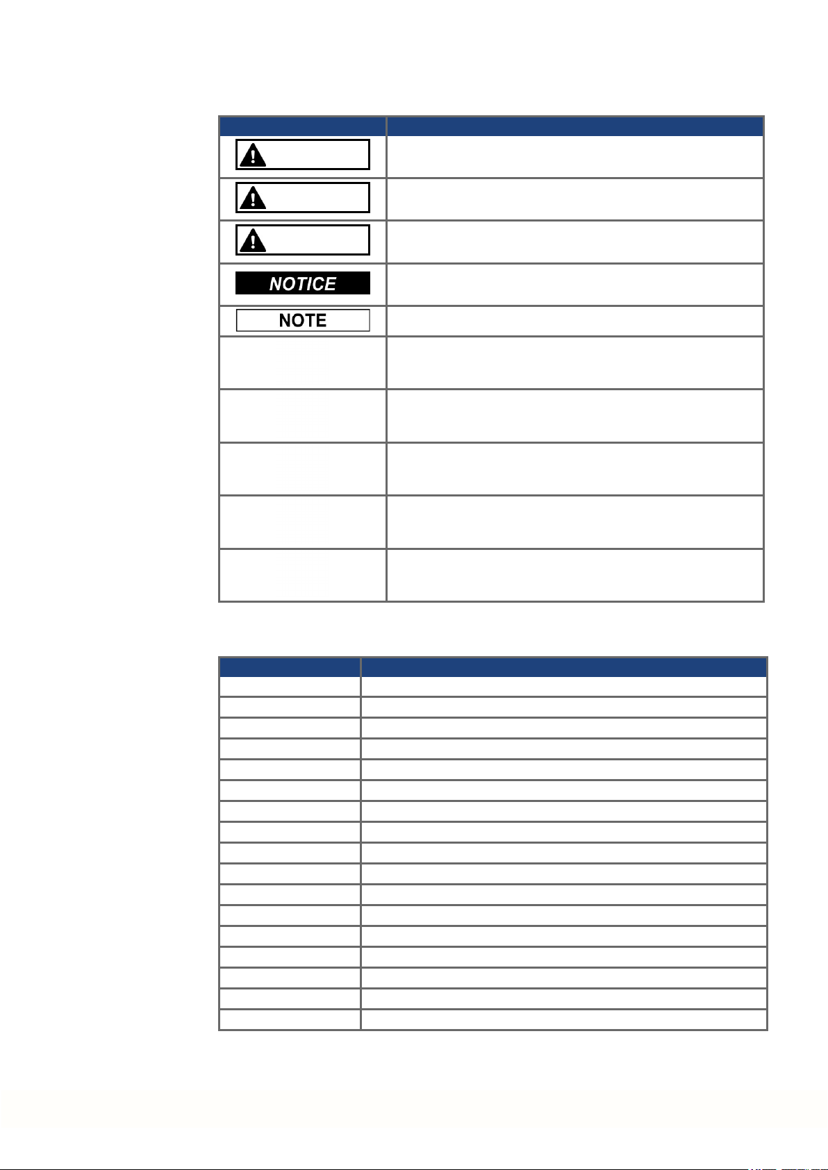
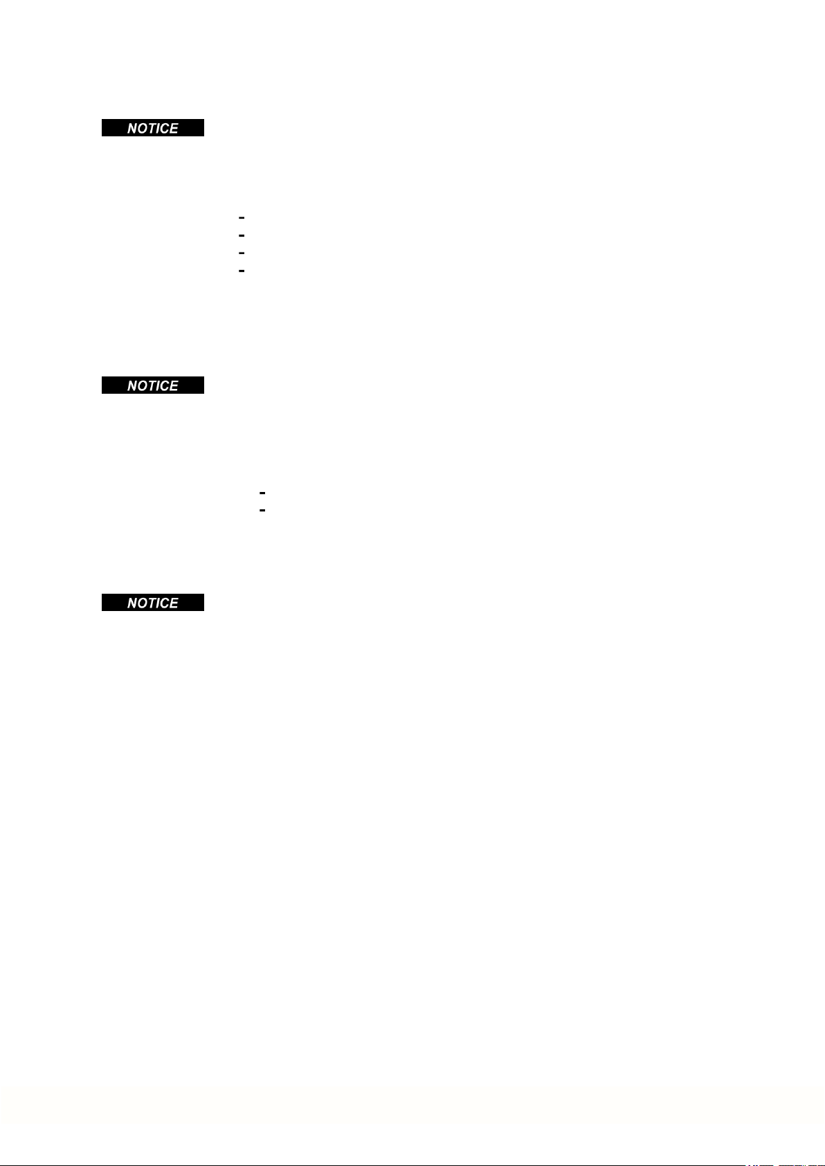
2.4 Symbols Used
Symbol Indication
DANGER
Indicates a hazardous situation which, if not avoided, will result in death or serious injury.
AKD-N Installation | 2 General
WARNING
CAUTION
Indicates a hazardous situation which, if not avoided, could
result in death or serious injury.
Indicates a hazardous situation which, if not avoided, could
result in minor or moderate injury.
Indicates situations which, if not avoided, couldresult in property damage.
This symbol indicates important notes.
Warning of a danger (general). The type of danger is specified
by the text next to the symbol.
Warning of danger from electricity and its effects.
Warning of danger from hot surface.
Warning of danger from suspended loads.
Warning of danger from automatic start.
2.5 Abbreviations Used
Abbreviation Meaning
(➜ # 53) "see page 53" in this document
CE Communité Européenne
EMC Electromagnetic compatibility
LED Light-emitting diode
OSSD Output signals Switching Device
PC Personal computer
PE Protective earth
PELV Protective extra low voltage
PLC Programmable logic control
PWM Pulse-width modulation
RAM Random access memory (volatile memory)
ROD Incremental encoder (A quad B)
Rth Specific thermal resistance
SELV Safety Extra Low Voltage
STO Safe torque off
VAC Volts, alternatingcurrent
VDC Volts, direct current
Kollmorgen | kdn.kollmorgen.com | February 2018 9
Page 10

AKD-N Installation | 3 Safety
3 Safety
3.1 You should pay attention to this 11
3.2 Use as Directed 13
3.3 Prohibited Use 13
3.4 Warning notes placed on the product 14
10 Kollmorgen | kdn.kollmorgen.com | February 2018
Page 11

3.1 You should pay attention to this
This section helps you to recognize and avoid dangers to people and objects.
Specialist staff required!
Only properly qualified personnel are permitted to perform such tasks as transport,
assembly, setup and maintenance. Qualified specialist staff are persons who are familiar
with the transport, installation, assembly, commissioningand operation of drives and who
bring theirrelevant minimum qualifications to bear ontheir duties:
Transport: only by personnel with knowledge of handling electrostatically sensitive components.
Unpacking: only by electrically qualified personnel.
Installation: only by electrically qualified personnel.
Basic tests / Setup: only by qualified personnel with knowledge of electrical engineering
anddrive technology
The qualifiedpersonnel must know and observe ISO 12100 / IEC 60364 / IEC 60664 and
national accident prevention regulations.
Read the documentation!
Read the availabledocumentation before installation and commissioning. Improper handling
of the drive can cause harm to peopleor damage to property. The operator of systems using
the AKD-N must ensure that all personnel who work with the drive readand understand the
manual beforeusing the drive.
AKD-N Installation | 3 Safety
Check Hardware Revision!
Check the HardwareRevision Numberof the product (see product label). This number is the
link between your product and the manual. The product Hardware Revision Numbermust
match the Hardware Revision Number on the coverpage of the manual.
Pay attention to the technical data!
Adhere to the technical data and the specifications on connection conditions. If permissible
voltage values or current values are exceeded, the drives can be damaged. Unsuitable motor
or wrong wiringwill damage the system components. Check the combination of drive and
motor. Comparethe rated voltageand current of the units.
Perform a risk assessment!
The manufacturer of the machine must generate a risk assessment for the machine, and take
appropriate measures to ensure that unforeseen movements cannot cause injury or damage
to any person or property. Additional requirements on specialist staff may also result from the
risk assessment.
Automatic Restart!
The drive might restart automatically after power on, voltagedip or interruption of the supply
voltage, depending on the parameter setting.
Risk of death or serious injury for humans working in the machine.
If the parameter DRV.ENDEFAULT is set to 1, then place a warning sign to the machine
(Warning: Automatic Restart at Power On) and ensure, that power on is not possible, while
humans are in a dangerous zone of the machine. In case of using an undervoltage protection
device, you must observe EN 60204-1:2006 chapter 7.5 .
Observe electrostatically sensitive components!
The drives contain electrostatically sensitive components which may be damagedby incorrect handling. Electrostatically discharge your body before touching the drive. Avoid contact
with highly insulating materials (artificial fabrics, plastic film etc.). Place the drive on a conductive surface.
Kollmorgen | kdn.kollmorgen.com | February 2018 11
Page 12

AKD-N Installation | 3 Safety
Hot surface!
Drives may have hot surfaces during operation. The housing can reach temperatures above
80°C. Risk of minor burns! Measure the temperature, and wait until the housing has cooled
down below 40 °C before touching it.
Earthing!
It is vital that you ensure that the drive is safely earthed to the PE (protective earth)system
in the machine. Risk of electric shock. Without low-resistance earthing no personal protection can be guaranteed.
Leakage Current!
Since the leakage current to PE is more than 3.5 mA, in compliance with IEC61800-5-1 the
PE connection must eitherbe doubled or a connecting cable with a cross-section >10 mm²
must be used. Deviating measures accordingto regional standards might be possible.
High voltages!
The equipment produces high electric voltages up to 900 V. Do not openor touch the equipment duringoperation. Keepall covers closed. The built-in LED does not safely indicate the
real voltage level.
Duringoperation, drives may have uncovered live sections, according to theirlevel of enclosureprotection. Wait at least 7 minutes after disconnecting the drive from the main supply
powerbefore touching potentially live sections of the equipment (such as contacts) or removing any connections.
Capacitors can have dangerous voltages present up to 7 minutes after switchingoff the supply power. Always measure the voltage in the DC bus link at connector X14 at AKD-C and
wait until the voltage is below 50 V beforehandling components.
Never undo any electrical connections to the drive while it is live. Thereis a danger of electrical arcing with damage to contacts and personal injury.
Reinforced Insulation
Thermal sensors, motor holdingbrakes and feedback systems built into the connected motor
must have reinforcedinsulation (according to IEC61800-5-1) against system components
with power voltage, accordingto the required applicationtest voltage. All Kollmorgen components meet these requirements.
Functional Safety
The STO safety implementation on the AKD is certified. The safety circuit implementation
used for the safety function "Safe Torque Off" in the drive is suited for SIL 2 accordingto IEC
62061 and PLd/ CAT3 according to ISO 13849-1. The assessment of the safety functions
according to EN13849 orEN 62061 must finally be done by the user.
Never modify the drive!
It is not allowed to modify the drive without permission by the manufacturer. Opening the
housing causes loss of warranty.
12 Kollmorgen | kdn.kollmorgen.com | February 2018
Page 13

3.2 Use as Directed
The AKD-N family of drives is exclusively intendedfor driving suitable synchronous servomotors with closed-loop control of torque, speed, and/orposition.
Drives are components that are built into electrical plants or machines and can only be operated as integral components of these plants or machines. The manufacturer of the machine
must generate a risk assessment for the machine.
When the drives are built into machines or plant, the drive must not be used until it has been
established that the machine or plant fulfills the requirements of the regional directives.
Kollmorgen Decentralized Drive System
AKD-N series drives must only be operated in a motion system with components from Kollmorgen. Required additional Kollmorgen components are the intelligent power supply AKDC, hybrid cables, motor power and feedback cables, servomotors.
Assembling
AKD-N drives must only be operated in machines suitable fortheambient conditions defined
on (➜ # 29). Optional finned heat sink may be necessary to keep the drive flange temperature below 85 °C and enable the axis to operate with maximum power. Observe the
information given in the Decentral System Projecting Guide.
Guide.
AKD-N Installation | 3 Safety
Wiring
Use only Kollmorgen CCNxN1 series of hybrid cables for connecting AKD-N and AKD-C
devices.
Power supply
AKD-N series drives must be powered by AKD-C intelligent power supplies with DC voltage
from 55 VDC up to 800 VDC.
Motor voltage rating
The rated voltage of the motors must be at least as high as the DC bus link voltagedivided
by √2 produced by the drive (U
Safe torque off
Review the section "Use as Directed" in the STO chapter(➜ # 42) beforeusing this safety
function (SIL2, PLd, category 3 according to ISO 13849).
The 24 VDC supply unit for local STO supply must accord to PELV (EN 60204-1) requirements.
3.3 Prohibited Use
Otheruse thanthat described in chapter “Use as directed” is not intended and can lead to personnel injuries and equipment damage.
The device may not be used
nMotor
>=UDC/√2).
with a machine that does not comply with appropriate national directives or standards,
for driving elevators,
in ships or offshoreapplications,
in applications with continuous, operational short circuits to the motor power contacts.
The use of the device in the following environments is also prohibited:
potentially explosive areas,
environments with corrosive and/or electrically conductive acids, alkaline solutions, oils,
vapors, dusts.
Wiring the system with hybrid cables from other manufacturers than Kollmorgen is not
allowed. Changing Kollmorgen cables or connectors is not allowed.
Kollmorgen | kdn.kollmorgen.com | February 2018 13
Page 14

AKD-N Installation | 3 Safety
3.4 Warning notes placed on the product
CAUTION
Risk of minor burns!
Duringoperation, the heat sink of the drive may reach
temperatures above 80°C (176°F).
Beforetouching the device, check the temperature and
wait until it has cooled below 40°C (104°F).
If these signs aredamaged, they must be replaced immediately.
14 Kollmorgen | kdn.kollmorgen.com | February 2018
Page 15

AKD-N Installation | 4 Handling
4 Handling
4.1 Packaging 16
4.2 Transport 16
4.3 Storage 16
4.4 Decommissioning 17
4.5 Maintenance and cleaning 17
4.6 Disassemble 17
4.7 System Repair 18
4.8 Disposal 18
Kollmorgen | kdn.kollmorgen.com | February 2018 15
Page 16
AKD-N Installation | 4 Handling
4.1 Packaging
The AKD-N packaging consists of recyclable cardboard with inserts and a label onthe outside of the box.
4.2 Transport
Model Package Dimensions
(mm) HxWxL
AKD-N00307 120x 295 x 370 3.2
AKD-N00607 120x 295 x 370 3.2
AKD-N01207 125x 410 x 295 approx. 3.5
Transport the AKD-N in accordance with IEC 61800-2 as follows:
Transport only by qualified personnel in the manufacturer’s original recyclablepackaging.
Avoid shocks while transporting.
Store at or below maximum stacking height of 8 cartons
Transport only within specified temperature ranges: -25 to +70 °C, max. rate of change 20
K/hour, class 2K3.
Transport only within specified humidity: maximum 95% relative humidity, no condensation, class 2K3.
The drives contain electrostatically sensitive components that can be damaged by incorrect
handling. Electrostatically discharge yourself before touching the drive. Avoid contact with
highly insulating materials, such as artificial fabrics and plastic films. Place the drive on a
conductive surface.
If the packaging is damaged, check the unit for visible damage. Inform the shipper and the
manufacturer of any damage to the package or product.
Total Weight
(kg)
4.3 Storage
Store the AKD-N in accordance with IEC 61800-2 as follows:
Store only in the manufacturer’s original recyclable packaging.
Store at or below maximum stacking height of 8 cartons
Store only within specified temperatureranges: -25 to +55 °C, max.rate of change 20
K/hour, class 1K4.
Storage only within specified humidity: 5 to 95% relative humidity, no condensation, class
1K3.
16 Kollmorgen | kdn.kollmorgen.com | February 2018
Page 17
4.4 Decommissioning
Only professional staff who are qualified in electrical engineeringare allowedto decommission parts of the system.
DANGER: Lethal Voltages!
There is a dangerof serious personal injury or death by electrical shock or electrical arcing.
Switch off the main switch of the switchgear cabinet.
Securethe system against restarting.
Block the main switch.
Wait at least 7 minutes after disconnecting.
4.5 Maintenance and cleaning
The device does not require maintenance. Opening the device voids the warranty. The inside
of the unit can only be cleaned by the manufacturer.
Do not immerse orspray the device. Avoid that liquid enters the device.
To clean the device exterior:
1. Decommission the device (see chapter4.4 "Decommissioning").
2. Casing: Clean with isopropanol or similar cleaningsolution.
Caution : Highly Flammable! Risk of injury by explosion and fire.
Observe the safety notes given on the cleaning liquid package.
Wait at least 30 minutes after cleaningbefore putting the device back into operation.
AKD-N Installation | 4 Handling
4.6 Disassemble
Only professional staff who are qualified in electrical engineeringare allowedto disassemble
parts of the system.
1. Decommission the device (see chapter4.4 "Decommissioning").
2. Check temperature.
3. Remove the connectors. Disconnect the potential earth connection last.
4. Demount: loosen the fastening screws. Remove the device.
CAUTION: High Temperature! Risk of minorburns. Duringoperation, the heat sink of
the drive may reach temperatures above 80°C (176°F). Before touching the device,
check the temperature andwait until it has cooled below 40°C (104°F).
Kollmorgen | kdn.kollmorgen.com | February 2018 17
Page 18
AKD-N Installation | 4 Handling
4.7 System Repair
Only professional staff who are qualified in electrical engineeringare allowedto exchange
parts of the drive system.
CAUTION: Automatic Start! During replacement work a combination of hazards and mul-
tiple episodes may occur.
Work on the electrical installationmay only be performed by trained andqualified personnel, in compliance with the regulations for safety at work, and only with use of prescribed personal safety equipment.
Exchange of AKD-N
Only the manufacturer can repair the device. Opening the device voids the warranty.
1. Decommission the device (see chapter4.4 "Decommissioning").
2. Demount the device (see chapter 4.6 "Disassemble").
3. Send thedevice to the manufacturer.
4. Install a new device as described in this manual.
5. Setup the system as described in this manual.
Exchange of other drive system parts
If parts of the drive system (for example cables) must be replaced, proceed as follows:
4.8 Disposal
1. Decommission the device (see chapter4.4 "Decommissioning").
2. Exchangethe parts.
3. Check all connections for correct fastening.
4. Setup the system as described in this manual.
To dispose the unit properly, contact a certified electronic scrap disposal merchant.
In accordance with the WEEE-2002/96/EC-Guidelines and similar, the manufacturer accepts
returns of old devices andaccessories for professional disposal. Transport costs are the
responsibility of the sender.
Send thedevices in the original packaging to the manufacturer address:
North America South America
KOLLMORGEN
201West Rock Road
Radford, VA 24141, USA
Europe Asia
KOLLMORGEN Europe GmbH
Pempelfurtstr. 1
40880 Ratingen, Germany
KOLLMORGEN
AvenidaTamboré-1077 Tamboré
Barueri - SP Brasil
CEP:06460-000, Brazil
KOLLMORGEN
Floor 4, Building 9, No. 518,
North Fuquan Road, Changning District,
Shanghai 200335, China
18 Kollmorgen | kdn.kollmorgen.com | February 2018
Page 19

AKD-N Installation | 5 Approvals
5 Approvals
5.1 Conformance with UL/cUL 20
5.2 Conformance with EC Low Voltage and EMC Directives 21
5.3 Conformance with EC Machinery Directive, Functional Safety 21
5.4 Conformance with EAC 22
5.5 Conformance with RoHS 22
5.6 Conformance with REACH 22
Kollmorgen | kdn.kollmorgen.com | February 2018 19
Page 20
AKD-N Installation | 5 Approvals
5.1 Conformance with UL/cUL
This drive is listed underUL (Underwriters Laboratories Inc.) file number E217428. UL Markings arecombined for
both AKD-C and AKD-N in one section.
5.1.1 UL Markings / Marquages UL
English Français
This product is suitable foruse on a circuit capableof delivering not more than 42,000 rms symmetrical amperes, 480 V maximum.
Maximum surrounding airtemperature 40°C. La température maximale de l'air ambiant de 40°C.
AKD-C are intendedto beused in a pollution
degree 2 environment.
AKD-C : Use 60/75°C copperwire only. AKD-C: Utilisez seulement un fil cuivre 60/75°C.
AKD-C : CAUTION Risk of Electrical Shock!
Capacitors can have dangerous voltages present
up to 7 minutes after switching off the supply
power. For increased safety, measurethe
voltage in the DC bus link and wait until the
voltage is below 50 V.
For use in Canada:
Transient surge suppression shall be installed on
the line side of this equipment and shall be rated
277V (phase to ground), 480 V (phase to phase),
suitable for overvoltage category III, and shall
provide protection for a rated impulse withstand
voltage peak of 2 kV.
Ce produit est conçu pour une utilisation sur un circuit
capable de fournir 42.000 ampères symétriques (rms)
maximum pour 480 V maximum.
AKD-C sont prévus pour une utilisation dans un
environnement de pollution de niveau 2.
AKD-C : ATTENTION: Risque de choc électrique!
Des tensions dangereuses peuvent persister dans les
condensateurs jusqu'à 7 minutes après la mise hors
tension. Pour plus de sécurité, mesurez la tension
dans la liaison de bus CC et attendez qu'elle soit
inférieure à 50 V.
Pour utilisation au Canada:
Suppression de surtension transitoire doit être installé
sur le côté de la ligne de ce matériel et doit être évalué
277 V (phase à terre) , 480 V (entre phases) , adapté à
la catégorie de surtension III , et doit fournir une protection pour un choc nominale supporter la tension de
crête de 2 kV.
The following fuse types are recommended for branch circuit protection for AKD-C01007-CBXX:
Les types de fusibles suivants sont recommandés pour protection de secteur pour AKD-C01007-CBXX:
Model/
Modèle
Nonrenewable Cartridge fuse CC, J 600VAC 20 A, 200 kA
The following table illustrates the torquerequirements for the field wiring connectors :
Le tableau suivant indique les spécifications de couple pour les connecteurs de câblage sur site:
Model/Modèle Torque/Couple serrage, LBIN (Nm) Wire size/Section de fil, AWG (mm²)
AKD-C X12 6.2 - 7.1 (0.7 - 0.8) 12 - 8 (4- 10)
AKD-C X20A 6.2 - 7.1 (0.7 - 0.8) 12 - 8 (4 - 10)
AKD-C X21A 6.2 - 7.1 (0.7 - 0.8) 12 - 8 (4 - 10)
AKD-C X14 6.2 - 7.1 (0.7 - 0.8) 12 - 8 (4- 10)
AKD-C X13 1.8 - 2.2 (0.2 - 0.25) 14 - 12(2.5 - 4)
AKD-C X15 1.8 - 2.2 (0.2 - 0.25) 20 - 18(0.5 - 0.8)
AKD-C X16 1.8 - 2.2 (0.2 - 0.25) 20 - 18(0.5 - 0.8)
Split gageof AKD-N screwed connectors: max. 2.8 mm.
Le gage de split des connecteurs vissé d'AKD-N: 2,8 mm max.
Cold plate for AKD-N: at 40°C surrounding air temperature and 680 VDC supply voltage:
Plaque froide pour AKD-N: à température ambiante 40°C et tension d'alimentation 680 VDC:
- AKD-N00307: 240 mm x 240 mm x 10 mm or equivalent (LxWxT, Aluminum cold plate, uncoated)
- AKD-N00607: 500 mm x 500 mm x 10 mm or equivalent (LxWxT, Aluminum cold plate, uncoated)
- AKD-N01207: 480 mm x 400 mm x 84 mm or equivalent (LxWxT, 31 vertical fins, Aluminum heat sink,
uncoated)
Class/
Classe
Voltage Rating/
Niveau de tension
Max. Fuse&SCC Rating/
Niveau maximum & SCC
20 Kollmorgen | kdn.kollmorgen.com | February 2018
Page 21
5.2 Conformance with EC Low Voltage and EMC Directives
EU Declarations of Conformity can be found on the Kollmorgen website.
Conformance with the EC EMC Directive 2014/30/EC and the Low Voltage Directive
2014/35/EC is mandatory for the supply of drives within the European Community.
The drives have been tested by an authorized testing laboratory in a defined configuration,
using the system components that are described in this documentation. Any divergence from
the configuration andinstallationdescribed in this documentation means that the user will be
responsiblefor carrying out new measurements to ensure conformance with regulatory
requirements.
Kollmorgen declares the conformity of the product series AKD-Nzzz07 with the followingdirectives:
EC Directive 2006/42/EC, Machinery Directive
Used harmonized standard EN13849-1 (2008)
EC Directive 2014/35/EC, Low Voltage Directive
Used harmonized standard EN61800-5-1 (2007)
EC Directive 2014/30/EC, EMC Directive
Used harmonized standard EN 61800-3 (2004)
The AKD-Nzzz07 meet the noise immunity requirements to the 2nd environmental category
(industrial environment). For noise emission the AKD-Nzzz07 meet the requirement to a
product of the Category C2 (motor cableup to 5 m).
AKD-N Installation | 5 Approvals
These devices can cause high-frequency interferences in non industrial environments and
may requiremeasures for interference suppression (such as additional external EMC filters).
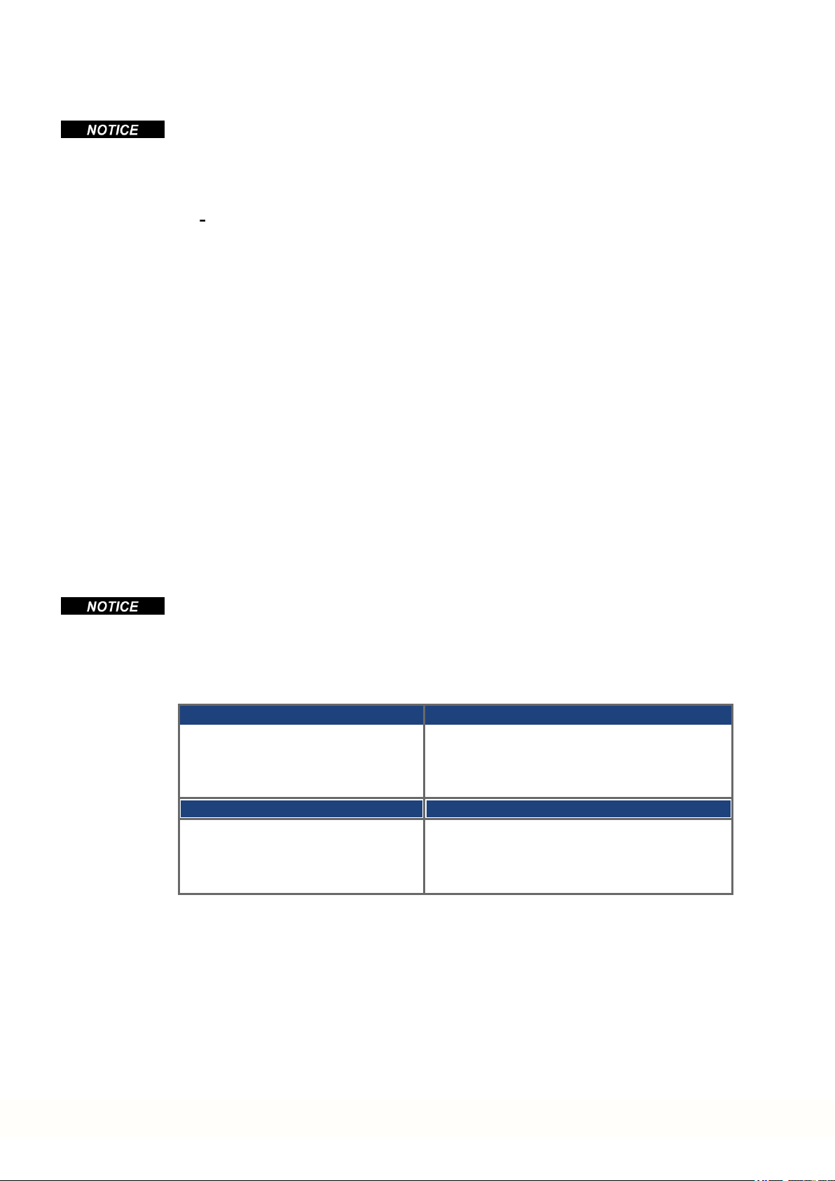
5.3 Conformance with EC Machinery Directive, Functional Safety
Conformance with the EC Machinery Directive 2006/42/EC is mandatory for the supply of
safety components within the European Community. The STO safety implementationon the
AKD-N is certified by TÜV. The safety circuit implementation used forthesafety function
"Safe Torque Off" in the drives is suited for SIL 2 according to IEC 62061 and PLd/ CAT3
according to ISO 13849-1.
Safe Torque Off (STO) string type (global)
Structure STO ISO
13849-1
AKD-C + 1 x AKD-N global PL d, CAT 3 ≥ 100 SIL 2 2.9E-08 97.08 20
AKD-C + 8 x AKD-N global PL d, CAT 3 ≥ 100 SIL 2 2.9E-08 99.44 20
See AKD-C Installation Manual for detailed information.
Safe Torque Off (STO) single drive type (local)
Structure STO ISO
13849-1
1 x AKD-N-DS/DT local PL d, CAT 3 ≥ 100 SIL 2 2.9E-08 97.12 20
MTTF
MTTF
d
d
IEC
62061
IEC
62061
PFH
[1/h]
PFH
[1/h]
SFF
[%]
SFF
[%]
T
M
[Years]
T
M
[Years]
Kollmorgen | kdn.kollmorgen.com | February 2018 21
Page 22

AKD-N Installation | 5 Approvals
5.4 Conformance with EAC
EAC is the abbreviation for Eurasian Conformity. The mark is used in the states of the Eurasian Customs Union (Russia, Belarus, Kazakhstan) similarto the European CE mark.
Kollmorgen declares, that the AKD has passed all requiredconformity procedures in a memberstate of the Eurasian Customs Union, and that the AKD meets all technical requirements
requested in the member states of the Eurasian Customs Union:
Low voltage (TP TC 020/2011)
Electromagnetic Compatibility (TP TC 004/2011)
Contact: Intelisys LLC. , Bakuninskaya Str. d 14, Building 10, RU-105005 Moskau
5.5 Conformance with RoHS
Directive 2011/65/EC of the European Union on the restriction of the use of certain hazardous substances in electrical and electronic equipment (RoHS) becameoperative as from
the 3rd of January, 2013. Following substances namely are involved
Lead (Pb), Cadmium (Cd), Hexavalent chromium (CrVI), Polybrominated biphenyls (PBB),
Polybrominated diphenyl ethers (PBDE), Mercury (Hg)
The AKD is manufactured in conformance with RoHS.
5.6 Conformance with REACH
EU Regulation no. 1907/2006 deals with the registration, evaluation, authorization and restriction of chemical substances 1 (abbreviated to "REACH").
AKD does not contain any substances (CMR substances, PBTsubstances, vPvB substances and similar hazardous substances stipulated in individual cases based onscientific
criteria) above 0.1 mass percent per product that are included onthe candidate list.
22 Kollmorgen | kdn.kollmorgen.com | February 2018
Page 23

AKD-N Installation | 6 Package
6 Package
6.1 Package Supplied 24
6.2 Nameplate 24
6.3 Part Number Scheme 25
Kollmorgen | kdn.kollmorgen.com | February 2018 23
Page 24

AKD-N Installation | 6 Package
6.1 Package Supplied
When a drive from the AKD-N series is ordered, the following items areincluded in the drive
package:
AKD-N with fourmounting clamps
Printedcopy of AKD-N Installation Manual
DVD containing the setup software, WorkBench, and all product documentation in digital
format.
Two connector covers M12 (forunused X3 and X6)
The mating connectors arenot included in the package.
The M23 connector cover for protecting X2 of the last AKD-N in a string is part of delivery of
the AKD-C package.
Accessories Sold Separately
Accessories must be ordered separately if required; refer to yourregional accessories
manual:
Heatsink 50 mm for AKD-N003/006
Heatsink 50 mm for AKD-N012
Heat conducting film
Motor cable, feedback cable
Hybrid cable for connection to next AKD-N
Cable for digital I/O connection
Cable for local STO connection (AKD-N-DS/DT only)
Cable for tertiary fieldbus (AKD-N-DF/DG only)
Connector AKD-N-JUMP-X5 for AKD-N-DS/DF with SFD3/DSL
6.2 Nameplate
Spare parts
Spare parts are described in theregional accessories manual:
Mounting clamps set
Sealing plugset for connectors
The nameplate depicted below is attachedto the side of the drive, sample data entries are for
a 12A type. Picture similar to the nameplate on thedevice.
24 Kollmorgen | kdn.kollmorgen.com | February 2018
Page 25

6.3 Part Number Scheme
Use the part numberscheme for product identification only, not for the order process,
because not all combinations of features are possible, always.
AKD-N Installation | 6 Package
Customization code includes language version of printed material and not safety relevant
customer specials.
Kollmorgen | kdn.kollmorgen.com | February 2018 25
Page 26

AKD-N Installation | 7 Technical description and data
7 Technical description and data
7.1 The AKD-N Family of Digital Drives 27
7.2 Mechanical Data 28
7.3 Electrical Data 28
7.4 Performance Data 28
7.5 Ambient Conditions, Ventilation, and Mounting Position 29
7.6 Inputs/Outputs 29
7.7 Connectors 30
7.8 Cable Requirements 31
7.9 Cable length definition 32
7.10 Dynamic Braking 33
7.11 Regen circuit 33
7.12 LED Codes 34
7.13 Switch-On and Switch-Off Behavior 35
7.14 Safe Torque Off (STO) 42
26 Kollmorgen | kdn.kollmorgen.com | February 2018
Page 27

7.1 The AKD-N Family of Digital Drives
Available AKD-N versions
Variant (short) Description Current Connectivity
AKD-N-DB
AKD-N-DG
AKD-N-DT
AKD-N-DF
AKD-N-DS
Standard features
Hybrid DC powerand fieldbus connection.
Hybrid motorconnection.
Hybrid DC powerand fieldbus connection.
Hybrid motorconnection. Local tertiary fieldbus interface.
Hybrid DC powerand fieldbus connection.
Hybrid motorconnection. Local drive STO
input.
Hybrid DC powerand fieldbus connection.
Dual cable motor power andfeedback connection. Local tertiary fieldbus interface.
Hybrid DC powerand fieldbus connection.
Dual cable motor power andfeedback connection. Local drive STO input.
AKD-N Installation | 7 Technical description and data
3 to 12 A EtherCAT, I/O
3 to 12 A
3 to 12 A
3 to 12 A
3 to 12 A
EtherCAT, I/O,
Local Fieldbus
EtherCAT, I/O,
Local STO
EtherCAT, I/O,
Local Fieldbus
EtherCAT, I/O,
Local STO
Supply voltagerange 55 VDC to 800 VDC
Motion bus onboard.
SFD, Hiperface DSL, Comcoder, ENDAT 2.1 & 2.2, BiSS, HIPERFACE, 1Vp-p Sin-Cos
encoders, incremental encoders support onboard.
Safe TorqueOff (STO) accordingto IEC 62061 SIL 2 onboard.
Use with synchronous servomotors, linear motors, and induction machines.
Power section
DCpower supply, voltage range 55VDC to 800 VDC.
Output stageIGBT module with floating current measurement.
Integrated safety
Appropriate insulation/creepagedistances andelectrical isolationfor safe electrical separation, perIEC 61800-5-1, between the power input/motor connections and the signal
electronics.
Temperature monitoringof the drive and motor.
Motor overload protection: foldback mechanism
SIL 2 safe torque off in accordance with IEC 62061
Operation and parameter setting
Using the setup softwareWorkBench for system setup via TCP/IP connected to X18 of
the intelligent powersupply AKD-C.
Full digital control
Digital current controller (670 ns)
Adjustabledigital velocity controller (62.5 µs)
Software option position controller (250 µs)
Inputs/Outputs
3 programmable digital inputs (➜ # 64)
1 programmable digital outputs (➜ # 64)
Kollmorgen | kdn.kollmorgen.com | February 2018 27
Page 28

AKD-N Installation | 7 Technical description and data
7.2 Mechanical Data
7.3 Electrical Data
Electrical data Units AKD-
Rated supply voltage V= 560to 680
Standby supply voltage V= 55
Rated input power for continuous operation kVA 1.5 3 7.7
Rated input current A 2.8 5.5 15
Permitted switch on/off frequency 1/h 30
Continuous output current (± 3%):
Continuous output power:
Peak output current (for 5 s, ± 3%) Arms 9 18 30
Peak output power (for 5 s) kW 3.9 7.8 15.6
Motor inductance min. mH 6.3 3.2 2.5
Motor inductance max. mH 600 300 250
Thermal dissipation, output stage disable W max. 6 max. 6 max. 6
Thermal dissipation at rated current W 37 71 150
Efficiency factor % 97 97 97
Technical data for regen circuit — (➜ # 33)
Motor holding brake current A max. 1 max. 1.5 max. 1.5
1)
cold plate: (LxWxT) 240x240x10, aluminum, surrounding temp. 40°C, supply voltage: 680V
2)
cold plate: (LxWxT) 500x500x10, aluminum, surrounding temp. 40°C, supply voltage: 680V
3)
heat sink: (LxWxT) 480x400x84, 31 vertical fins, aluminum, surrounding temp. 40°C, supply
voltage: 680V
Mechanical data Units AKD
-N00307
AKD
-N00607
AKD
-N01207
Weight kg 1.6 approx. 2.1
Height mm 75 75
Width mm 130 130
Length, housing mm 201 252
Length, with connectors
mm 247 297
andmounting clamps
Optimum cooling situation
N00307
Arms 3
1)
AKD-
N00607
2)
6
AKD-
N01207
12
(cold plate size definition fulfilled)
Free convection cooling, unmounted Arms 1.8 1.7 0.8
Optimum cooling situation
kW 1.3 2.6 5
(cold plate size definition fulfilled)
Free convection cooling, unmounted kW 0.8 0.7 0.3
3)
7.4 Performance Data
Performance Data Units AKD
Switching frequency of output stage kHz 10 8
Voltagerise speed dU/dt kV/µs 7.2
Bandwidth of current controller kHz 2.5
Bandwidth of velocity controller (scalable) Hz 0 to 750
Bandwidth of position controller (scalable) Hz 1 to 250
28 Kollmorgen | kdn.kollmorgen.com | February 2018
N00307
AKD-
N00607/01207
Page 29

AKD-N Installation | 7 Technical description and data
7.5 Ambient Conditions, Ventilation, and Mounting Position
Storage (➜ # 16)
Transport (➜ # 16)
Surrounding air temperature in operation
Humidity in operation Relative humidity 5 to 95%, no condensation, class 3K4
Site altitude Up to 1000 meters above meansea level without restriction
Pollution level Pollution level 3 as per IEC 60664-1
Vibrations Class 3M5 according to IEC 60721-3-3
Environmental area IP65/IP67 according to IEC 60529, UL Type 4x
Mounting position All orientations allowed, observe preferred position, (➜ # 52)
Cold plate size Aluminum cold plate minimum size:
Ventilation Free air convection
-10°C to +40 °C underrated conditions
+40 °C to +55 °C with continuous current derating 4 % per Kelvin
1,000 to max. 2,000 meters above mean sea level with current
derating1.5%/100 m
AKD-N00307: cold plate 350x350x10 mm
AKD-N00607: cold plate 500x500x10 mm
AKD-N01207: heat sink 480x400x84mm, 31 fins
The drive operates to full ratings, if the mountingsurface for the
cold plate is between -10°C and +85°C and the surrounding air
temperature is between -10°C and +40°C.
7.6 Inputs/Outputs
Interface Electrical Data
Digital inputs (X3) as per IEC61131-2type 1
Digital outputs (X3) as per IEC61131-2 type 1
STO input (X6 option DS/DT)
STO outputs (X3, option DS/DT) as per IEC61131-2type 1
ON: 15 VDC to 30 VDC, 2 mA to 15 mA
OFF: -3 VDC to 5 VDC, < 1 mA
galvanic isolation for 30 VDC
2 highspeed inputs: update rate 2 µs
1 standard input: update rate 250 µs
max. 30 VDC, 100 mA
short circuit proof
galvanic isolation for 30 VDC
Update rate 250 µs
ON: 18 VDC to 30 VDC, 50 mA to 100 mA
OFF: 0 VDC to 12 VDC, < 50 mA
galvanic isolation for 60 VDC
max. 30 VDC, 100 mA
short circuit proof
galvanic isolation for 30 VDC
Update rate 62.5 µs
Kollmorgen | kdn.kollmorgen.com | February 2018 29
Page 30

AKD-N Installation | 7 Technical description and data
7.7 Connectors
Given voltage andcurrent data are thelowest values allowed by UL and CE.
Connector Type Max. Cross Section Current Voltage*
Hybrid IN, X1 Hybrid Connector
(male), 7 poles
Hybrid OUT, X2 Hybrid Connector
(female), 7 poles
Digital I/O, X3 Connector (female),
8 poles
Motor/Hybrid, X4 Connector (female),
8 poles
Feedback X5 Connector (male),
17 poles
STO/Fieldbus, X6 Connector (female),
4 poles
* Rated voltage with pollution level 2, use Kollmorgencables only.
4 x 0.34mm², 22 awg
3 x 2.5 mm², 14 awg
4 x 0.34mm², 22 awg
3 x 2.5 mm², 14 awg
8 x 0.34 mm², 22 awg 2 A 30 V
4 x 2.5 mm², 14 awg
4 x 1.0 mm², 18 awg
17 x 0.75 mm², 20 awg 3.6 A 63 V
4 x 0.34 mm², 22 awg 1 A 50 V
0.5 A
18 A
0.5 A
18 A
15 A
10 A
30 V
850V
30 V
850V
630V
30 V
30 Kollmorgen | kdn.kollmorgen.com | February 2018
Page 31

7.8 Cable Requirements
For information on the chemical, mechanical, and electrical characteristics of the cables
please referto the accessories manual or contact customer support.
Use Kollmorgen hybrid, motor, and feedback cables only. You will lose system warranty, if
you use hybrid, motor orfeedback cables from a manufacturer other than Kollmorgen.
Cable from Cable to Cable type Cross
AKD-C X20/X21 AKD-N X1, hybrid
AKD-N X2 AKD-N X1, hybrid
AKD-N X3 Digital I/O Phoenix SAC-
AKD-N-DF/DG X6 D-coded, Tertiary Fieldbus Phoenix SAC-
AKD-N-DS/DT X6 A-coded, Single Drive STO
AKD-N AKM Motor
AKD-N-DB/DG/DT X4 Motor Power with brake and
AKD-N-DF/DS X4 Motor Power without brake
AKD-N-DF/DS X4 Motor Power with brake
AKD-N-DF/DS X5 Motor Feedback SFD
AKD-N-DF/DS X5 Motor Feedback Comcoder
AKD-N-DF/DS X5 Motor Feedback EnDat/BiSS
AKD-N-DF/DS X5 Motor Feedback Hiperface
AKD-N Installation | 7 Technical description and data
switch
Hiperface DSL feedback,
hybrid
CCNCN1-025
CCNNN1-025
8P-M12MS
4P-M12MSD
Phoenix SAC-
4P-M12MS
CCJNAz-015
CM0NAz-015
CM1NAz-015
CFSNAz-002
CFCNAz-002
CFENAz-002
CFHNA1-002
section
3 x 2.5 mm²
4 x 0.25 mm²
3 x 2.5 mm²
4 x 0.25 mm²
8 x 0.25 mm²
2 x 2 x 0.14 mm²
4 x 0.34 mm²
4 x 1.5 mm²
2 x 0.75 mm²
2 x 0.34 mm²
4 x 1.5 mm²
4 x 1.5 mm²
2 x 0.75 mm²
4 x 2 x 0.25 mm²
7 x 2 x 0.25 mm²
7 x 2 x 0.25 mm²
7 x 2 x 0.25 mm²
z: 1 = Connector M23, 2 = Connector SpeedTec (CC only)
Followed by length coding. Contact your Kollmorgen sales representative.
Example, similar cables are available from other distributors.
Kollmorgen | kdn.kollmorgen.com | February 2018 31
Page 32

AKD-N Installation | 7 Technical description and data
7.9 Cable length definition
AKD-C offers two separate strings to connect up to 8 AKD-N to each of them. Maximum
total cable length for each string is 100 m. For system topology information refer to (➜ # 57)
Cable
Type
CCNCN1 AKD-C to AKD-N, hybrid 3, 6, 12, 24, 36 40
CCNNN1 AKD-N to AKD-N, hybrid 0.25, 0.5, ... , 2.0 (steps 0.25m)
CCJNAz AKD-N-DG/DT to Motor, hybrid 0.2, 0.3, ... , 1.0 (steps 0.1m)
CMxNAz AKD-N-DF/DS to Motor, Power
CFyNAz AKD-N-DF/DS to Motor, Feed-
single line X13 +24 V/GND, X15 Digital I/Os, X16 STO Signals 30
z: 1 = Connector M23, 2 = Connector SpeedTec (CC only)
Cable usage Available Length (m) Max.
Length (m)
2.5, 3.0, ... , 25 (steps 0.5m)
1.25, 1.5, ... , 2.0 (steps 0.25m)
2.5, 3.0, ... , 5.0 (steps 0.5m)
back
25
5
32 Kollmorgen | kdn.kollmorgen.com | February 2018
Page 33

7.10 Dynamic Braking
Dynamic brakingis a method to slow down a servo system by dissipating themechanical
energy driven by the motor back EMF. The AKD-N has a built in advanceddynamic braking
mode which operates fully in hardware. When activated, the drive shorts the motor terminals
in phase with the back EMF (q axis) but continues to operate the non-force producing current
loop(d-axis) with 0 current. This forces all of the dynamic braking current to be stopping current and insures the fastest stopping/amp of motor terminal current.
When current is not being limited, the mechanical energy is being dissipated in the motor
resistance.
When current is being limited, energy is returned to the drive bus capacitors.
The drive also limits the maximum dynamic braking motorterminal current via the
DRV.DBILIMIT parameter to insure that the drive, motor, and customer loaddo not see
excessive currents/forces.
Whether andhow the AKD-N uses dynamic braking depends on (DRV.DISMODE).
7.11 Regen circuit
When the amount of returned energy builds the bus capacitor voltage up enough the AKD-C
activates the regen circuit to start dumping the returned energy in the regen resistor (also
called regenerative or brake resistor). The AKD-C has an internal regenresistor is resistor, an
additional external one can beconnected to X14.
External regen resistors are described in the regional AKD Accessories Manual.
AKD-N Installation | 7 Technical description and data
7.11.1 Functional description
When the amount of returned energy builds the bus capacitor voltage up enough the AKD-C
activates the brake chopper to start dumping the returned energy in the regen resistor at the
AKD-C (internally or connected to terminal X14).
90% of the combined power of all the coupled drives is always available for peak and continuous power.
Switch-off on over voltage
The drive that has the lowest switch-off threshold (resulting from tolerances) reports an overvoltage fault if the DC bus threshold is exceeded. The drive power stage is disabledand the
loadcoasts to a stop with the fault message “F501Bus Over voltage". The AKD-C fault relay
contact (terminals X15/5-6) is opened due to this fault.
7.11.2 Technical data
Technical data are listed in the AKD -C Installation Manual.
Kollmorgen | kdn.kollmorgen.com | February 2018 33
Page 34

AKD-N Installation | 7 Technical description and data
7.12 LED Codes
The built-in LED indicates the status of the drive after the 24 V supply for AKD-C is switched
on. If the AKD-C service connection to the PC or to the PAC doesn't work, then the LED is
the only way to get information.
DANGER
High voltage up to 900 V
There is a danger of serious personal injury or death by electrical shock or
electrical arcing. The built-in LED does not indicate the real voltage level.
Always measure the voltage in the DC bus link at connector X14 at
AKD-C and
wait until the voltage is below 50 V before handling any component in
the decentral servo system.
The LED delivers information with three colors (red, green, yellow) andblink frequency. Specialist can analyze the blink frequency, more information to that can be found in the
WorkBench online help.
Basic information
Color Remarks
Green Enabled and running
blink green/orange Enabled and running with warning
blink orange Safe bus voltage
blink red/orange/green Fault
34 Kollmorgen | kdn.kollmorgen.com | February 2018
Page 35

7.13 Switch-On and Switch-Off Behavior
Behavior of “holding brake” function
Drives with an enabled holding brake function have a special timing for switching on and off
the output stage. Events that remove the DRV.ACTIVE signal trigger the holdingbrake to
apply. As with all electronic circuits, the general ruleapplies that there is a possibility of the
internal holding brake module failing.
Functional safety, for example with hanging load (vertical axes), requires an additional mechanical brake which must be safely operated, for example by a safety control.
If velocity drops below threshold CS.VTHRESH or timeout occurs during a stop procedure,
the brake is applied. Set parameter MOTOR.BRAKEIMM to 1 with vertical axes, to apply the
motor holding brake immediately after faults or Hardware Disable.
Safety function STO
With the functional safe function STO, the drive can be secured on standstill using its internal
electronics so that even when power is being supplied, the drive shaft is protected against
unintentional restart. The chapter “Safe Torque Off (STO)” describes how to use the STO
function (➜ # 42).
7.13.1 Switch-on behavior in standard operation
The diagram below illustrates the correct functional sequence for switching the drive on.
AKD-N Installation | 7 Technical description and data
Kollmorgen | kdn.kollmorgen.com | February 2018 35
Page 36

AKD-N Installation | 7 Technical description and data
7.13.2 Switch-off behavior
The AKD-C 24 V supply must remain constant. Hardware Enable input disables all AKD-N
powerstages immediately. Configured Digital Inputs and fieldbus commands can be used to
perform controlledstops.
The control functions Stop, Emergency Stop and Emergency Off aredefined by IEC 60204.
Notes for safety aspects of these functions can be found in ISO 13849 and IEC 62061.
The parameter DRV.DISMODE must be set to 2 to implement the different stop categories.
Consult the WorkBench Online Help for configuring the parameter.
WARNING
No Functional Safety
Serious injury could result when a suspended load is not properly
blocked. Functional safety, e.g. with hanging load (vertical axes), requires
an additional mechanical brake which must be safely operated, for
example by a safety control.
Add a safe mechanical blocking (for instance, a motor-holding brake).
Set parameter MOTOR.BRAKEIMM to 1 with vertical axes, to apply the
motor holding brake immediately after faults or Hardware Disable.
7.13.2.1 Switch-off behavior using a digital input (controlled stop)
This is a category 2 stop according to IEC 60204. A digital input can be configured to bring
the motorto a controlled stop andthen disable the drive and apply the holding brake (if
present). See the WorkBench Online Help for information on configuring Digital Inputs.
If velocity drops below threshold CS.VTHRESH or timeout occurs brake is applied.
36 Kollmorgen | kdn.kollmorgen.com | February 2018
Page 37

AKD-N Installation | 7 Technical description and data
7.13.2.2 Switch-off behavior using the DRV.DIS command
The enable/disable button in WorkBench issues a drv.dis command internally to the drive.
See WorkBench Online Help for configuring inputs and softwarecommands. Sometimes this
enable signal is called "Software Enable" (SW-Enable).
DRV.DISMODE0Disable axis immediately, if velocity drops below threshold
CS.VTHRESH or timeout occurs brake is applied. Category 0 stop
according to IEC 60204 (➜ # 42).
DRV.DISMODE2Use controlled stop to disabledrive, if velocity drops below threshold
CS.VTHRESH or timeout occurs brake is applied. Category 1 stop
according to IEC 60204 (➜ # 42).
If velocity drops below threshold CS.VTHRESH or timeout occurs brake is applied.
Kollmorgen | kdn.kollmorgen.com | February 2018 37
Page 38

AKD-N Installation | 7 Technical description and data
7.13.2.3 Switch-off behavior using HW Enable input on AKD-C (uncontrolled stop)
This is a category 0 stop according to IEC 60204. The hardware enable input disables the
AKD-N power stage immediately.
If velocity drops below threshold CS.VTHRESH or timeout occurs the motor holding brake is
applied. Set parameter MOTOR.BRAKEIMM to 1 with vertical axes, to apply the motor holding brake immediately after Hardware Disable.
38 Kollmorgen | kdn.kollmorgen.com | February 2018
Page 39

7.13.2.4 Switch-off behavior in the event of a fault
The behavior of the drive always depends on the fault type and the setting of a number of different parameters (DRV.DISMODE, VBUS.UVFTHRESH, CS.VTHRESH, and others; see
the WorkBench Online Help formore details).See the Drive Fault and Warning Messages
and Remedies section of the WorkBench Online Help for a table describing the specific behavior of each fault. The follwing pages show examples for the possible fault behaviors.
Switch-off behavior for faults that cause an immediate power stage disable
This is a category 0 stop according to IEC 60204.
AKD-N Installation | 7 Technical description and data
If velocity drops below threshold CS.VTHRESH or timeout occurs the motor holding brake is
applied. Set parameter MOTOR.BRAKEIMM to 1 with vertical axes, to apply the motor holding brake immediately after faults.
Kollmorgen | kdn.kollmorgen.com | February 2018 39
Page 40

AKD-N Installation | 7 Technical description and data
Switch-off behavior for faults that cause dynamic braking
This is a category 0 stop according to IEC 60204.
If velocity drops below threshold CS.VTHRESH or timeout occurs brake is applied .
40 Kollmorgen | kdn.kollmorgen.com | February 2018
Page 41

AKD-N Installation | 7 Technical description and data
Switch-off behavior for faults that cause a controlled stop
This is a category 1 stop according to IEC 60204.
If velocity drops below threshold CS.VTHRESH or timeout occurs brake is applied .
Kollmorgen | kdn.kollmorgen.com | February 2018 41
Page 42

AKD-N Installation | 7 Technical description and data
7.14 Safe Torque Off (STO)
The STO functionality of AKD-N with option "DB" or "DF" or "DG" is controlled by the AKD-C
smart powersupply via the specific string, wherethe AKD-N is connected to. This STO topology is called "Global STO" or "String STO".
AKD-N drives with option "DS" or "DT" offer anadditional connector X6 with a digital STOEnable input. This STO functionality is called "Local STO". These drive variants cannot be
safety controlled by the global STO functionality.
7.14.1 Global STO, control via AKD-C
Connector X16 on theAKD-C offers access to all STO (Safe Torque Off) signals of the
decentral drive system powered by this AKD-C . There is one STO-Enable input and one
STO-Status output for each DC Power string.
The global STO function is described in the AKD-C Installation Manual.
Applicationexamples can be found in the Decentralized System Projecting Guide.
The global STO function uses the following devices: AKD-C, AKD-N without option
"DS/DT", Kollmorgen hybrid connection cable.
In case of using an AKD-N with option "DS" or "DT" (local STO input), the global STOEnable signal will have not influence to this specific drive. The local STO-Status of this drive
nevertheless is monitored in the string STO-Status.
7.14.2 Local STO, control via digital input on AKD-N-DS/DT
Option"DS" and "DT" on the AKD-N offer local STO-Enable functionality. There is one STOEnable input on X6 andone STO-Status output on X3 for the drive. The STO-Status outputs
on X3 are available only with AKD-N drives with option"DS" or "DT".
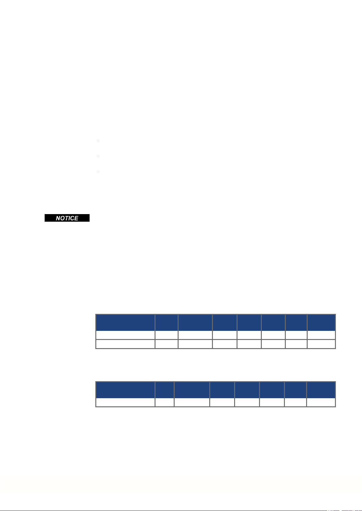
7.14.3 Safety characteristic data
The systems are described with the following characteristics:
Structure STO ISO
13849-1
AKD-C + 1 x AKD-N global PL d, CAT 3 ≥ 100 SIL 2 2.9E-08 97.08 20
AKD-C + 8 x AKD-N global PL d, CAT 3 ≥ 100 SIL 2 2.9E-08 99.44 20
1 x AKD-N-DS/DT local PL d, CAT 3 ≥ 100 SIL 2 2.9E-08 97.12 20
A very unlikely but possible event can happen, if within a very short time 2 not adjacent
IGBTs will have a short circuit. In such case a movement of a maximum angle of 120° (electrical) can happen. This effect can only happen if the drive is in the function STO. If the total
failurerate of the IGBT is 120 FIT normally for such short circuit 60 FIT will be valid (50:50
model). By such event 2 specific IGBTs have to fail at same time. The calculation shows a
probability of 1.5 * 10
-15
perhour (without common cause failure). Even if the STO function
will be issued fora whole year, this event will only happen every 100 Billion years.
MTTF
d
IEC
62061
PFH
[1/h]
SFF
[%]
T
M
[Years]
42 Kollmorgen | kdn.kollmorgen.com | February 2018
Page 43

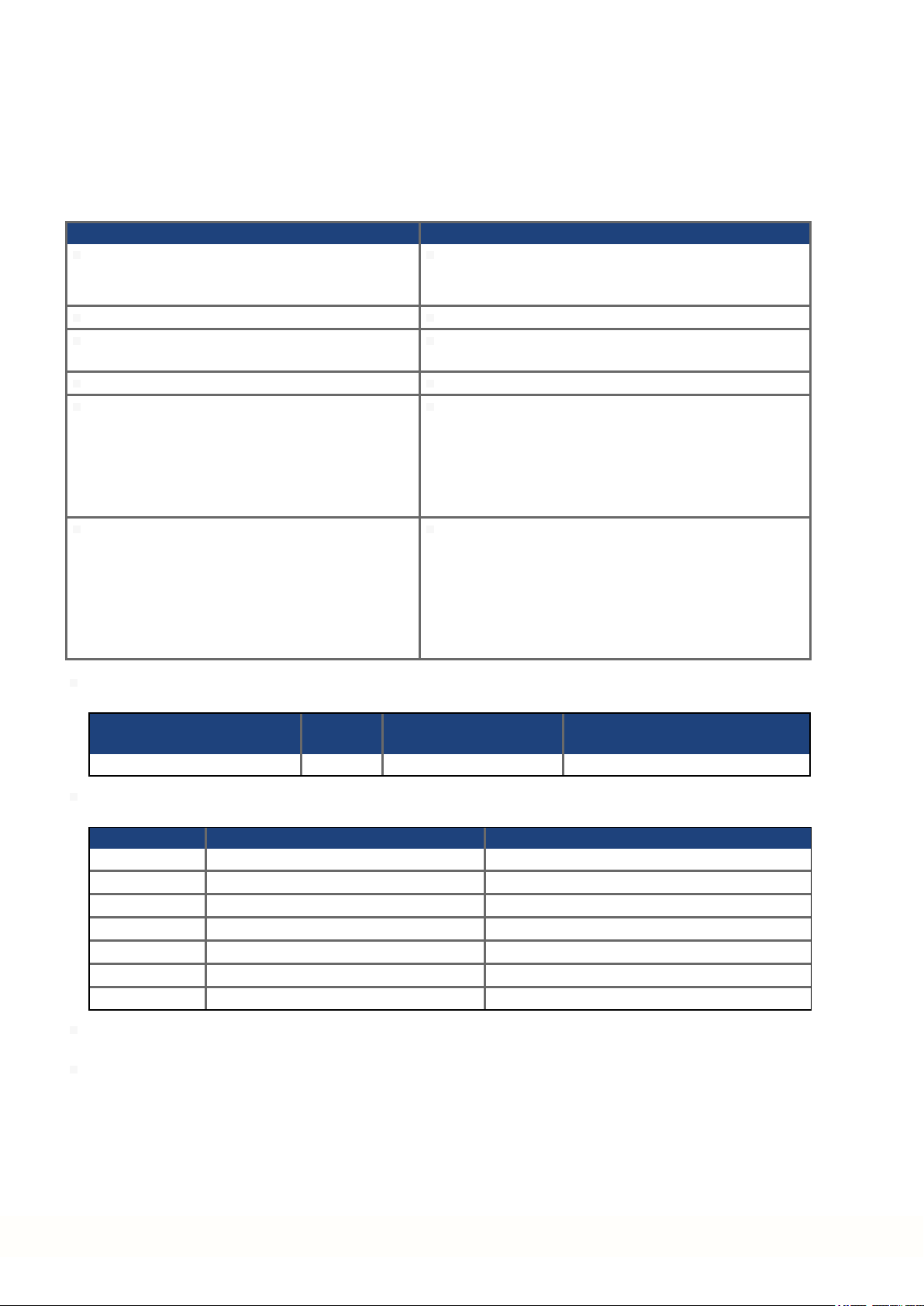
7.14.4 Use as directed
The STO function is exclusively intendedto provide a functional safe torque off of the drive.
To achieve this functional safety, the wiring of the safety circuits must meet the safety
requirements of IEC 60204, ISO 12100 and ISO 13849.
If the local STO function is in use, then theinput STO must be connected to the exit of a
safety control or a safety relay, which at least meets the requirements of PLd, CAT 3 according to ISO 13849.
The 24 VDC supply unit for local STO supply must accord to PELV (EN 60204-1) requirements.
7.14.5 Prohibited use
The STO function must not be used if the drive is to be made inactive for the following reasons:
Cleaning, maintenance and repair operations, long inoperative periods. In such cases, the
entire system should be disconnected from the supply and secured (main switch).
Emergency-Off situations. In an Emergency-Off situation, the main relay is switched off
(by the Emergency-Off button).
Wiring the system with hybrid cables from other manufacturers than Kollmorgen is not
allowed.
Changing cables or connectors is not allowed.
Do not use STO Status signals for functional safety.
AKD-N Installation | 7 Technical description and data
7.14.6 Response Time
Global STO
The delay from falling edge at global STO Enableinput until energy supply to the motors is
interrupted, depends on the number of connected AKD-N to the string. Maximum reaction
time is 10 ms. The more AKD-N are connected to the string, the shorter is the reaction time.
Local STO
The delay from falling edge at local STO Enable input until energy supply to the motor is interrupted is maximum 10 ms.
7.14.7 Enclosure, wiring
Avoid pollution of the connectors with conductive obstacles Observe the requiredambient
conditions as described in chapter (➜ # 29). The AKD-N can be used in an environment that
meets IP67.
The cables must be laid durably (firmly), protected from outside damage (for example, by laying the cable in a duct), placed in different sheathed cables, or protected individually by
groundingconnection.
Wiring must meet the requirements of the standard IEC 60204-1.
Maximum cablelength for safety relevant I/Os and for the 24V supply is 30 m.
Kollmorgen | kdn.kollmorgen.com | February 2018 43
Page 44

AKD-N Installation | 7 Technical description and data
7.14.8 Local STO safety instructions
WARNING
No Brake Power
Serious injury could result when a suspended load is not properly
blocked. The drive cannot hold a vertical load when STO is active.
The drives have not to be used for driving elevators.
Add a safe mechanical blocking (for instance, a motor-holding brake).
CAUTION
Automatic Restart
Risk of death or serious injury for humans working in the machine. The
drive might restart automatically after power on, voltage dip or interruption
of the supply voltage, depending on the parameter setting. If parameter
DRV.ENDEFAULT is set to 1,
then place a warning sign ("WARNING: Possible Automatic Restart" or
similar) to the machine.
Ensure, that power on is not possible, while humans are in a dangerous zone of the machine.
In case of using an undervoltage protection device, you must observe
EN 60204-1:2006 chapter 7.5 .
CAUTION
High electrical voltage
Risk of electrical shock! The STO function does not provide an electrical
separation from the power output. If access to the motor power terminals is
necessary,
disconnected the drive from AKD-C,
consider the discharging time of the DC-Bus link.
If the safety function STO is automatically activated by a control system, then make sure
that the output of the control is monitored for possible malfunction. The monitoring can be
used to prevent a faulty output from unintentionally activating the STO function. Since the
local STO function is a single-channel system, erroneous engaging will not be recognized.
It is not possible to perform a controlled brake if the drive controlled STO-Enable is off. If controlledbraking before the use of the STO function is necessary, the drive must be braked and
the input STO must be separated time-delayed from +24 V .
In case of a specific doublefault within a very short time (➜ # 42) a singlemovement of a
maximum angle of 120° (electrical) can happen. This effect can only happen if the drive is in
the function STO. Even if the STO function will be issued for a whole year, this event will
only happen every 100 Billion years.
The STO Status signals areinformal and not relevant for functional safety.
44 Kollmorgen | kdn.kollmorgen.com | February 2018
Page 45

7.14.9 Technical data and pinout local STO
The local STO input is not compatible with IEC 61131-2.
STO-Enable input Input does not match IEC61131-2
ON: 18 VDC to 30 VDC, 100mA
OFF: 0 VDC to 12 VDC, < 50 mA
Galvanic isolationfor 250 VDC
Tolerated OSSD pulse duration 0.3 ms
STO-Status outputs As per IEC61131-2 type 1
Max. 30 VDC, 100 mA
Galvanic isolationfor 250 VDC
24 VDC Power supply
Wiring diagram local STO-Enable
M12, A-coded X6 Pinout Description
PELV acc. to EN 60204-1
Output 24 VDC +/-10%
1 STO-Enable +
AKD-N Installation | 7 Technical description and data
2 STO-Enable 3 n.c.
4 n.c.
Wiring diagram local STO-Status
M12, A-coded X3 Pinout Description
1,2 see (➜ # 66)
3 STO Status -
4 STO Status +
5,6,7,8 see(➜ # 66)
Kollmorgen | kdn.kollmorgen.com | February 2018 45
Page 46

AKD-N Installation | 7 Technical description and data
7.14.10 Functional description local STO
With AKD-N with option DS or DT, an additional digital input (STO) releases the poweroutput
stage of the drive as longas a 24 V signal is applied to this input. When the local STO function (Safe Torque Off) is not needed, thentheinput STO must be connected directly to +24
VDC. The function is then bypassed and cannot be used.
The global STO signal will have no influence to this drive. The local STO input on the AKD-N
has no influence to the global STO as well.
Local
STO-Enable
0 V no high yes no
0 V yes high yes no
+24 V no low no no
+24 V yes low no yes
When STO function is engaged during operation by separating input STO-Enable from 24V,
the connected motorslows down without control.
Use the followingfunctional sequence when the STO function is used:
1. Brake the drive in a controlled manner(speed setpoint = 0 V).
2. When speed = 0 rpm, disable the drive (enable = 0 V).
3. If a suspended load is present, block the drive mechanically.
4. Activate the STO function.
It is not possible to perform a controlled brake if the drive STO-Enable is off.
If controlled braking priorto the use of the STO function is necessary, the drive must be
braked first and the input STO must be separated from +24 V time-delayed.
7.14.10.1 Signal diagram (sequence)
The diagram below shows how to use STO function for a safe drive stop and fault free operation of the drive. This sequence is valid for local andglobal STO functionality.
1. Brake the drive in a controlled manner (speed setpoint = 0 V).
2. When speed = 0 rpm, disable thedrive (Enable = 0 V).
3. Activate the STO function (local STO-Enable = 0 V)
4. For restart you must reset the safety device.
HW Enable
String
Local
STO-Status
Safety acc.
to SIL2
Drive can
produce Torque
46 Kollmorgen | kdn.kollmorgen.com | February 2018
Page 47

7.14.11 Functional test
You must test the safe torque off function after initial start of the drive, after each interference into the wiring of the drive, or after exchange of one or several components of the
drive.
7.14.11.1 Global STO
First Method:
1. Stop drives in the string with setpoint 0 V. Keepdrives enabled.
DANGER: Do not enter hazardous area!
2. Activate the global STO function for example by opening protective screen of the string,
where the drives are connected (voltage at AKD-C X16/6 orX16/8 0V).
3. The AKD-C fault contact opens, the corresponding string STO-Status message (X16/1 or
X16/2)changes the voltagelevel, the drives lose torque and slow down to zero speed
without control.
Second Method:
1. Stop all drives in the string with setpoint 0 V, disablethe string.
2. Activate the global STO function, for example, by opening protective screen (voltage at
AKD-C X16/6 orX16/8 0V)
3. The corresponding stringSTO-Status message (X16/1 or X16/2) changes the voltage
level, the string cannot be enabled.
AKD-N Installation | 7 Technical description and data
7.14.11.2 Local STO
First Method:
1. Stop the drive with setpoint 0 V. Keepdrive enabled.
2. Activate the local STO function for example by opening protective screen of the drive,
3. The drive lose toque andslows down to zerospeed without control.
Second Method:
1. Stop the drive with setpoint 0 V, disable drive.
2. Activate the STO function, for example, by opening protective screen (voltage at AKD-N
3. The drive cannot be enabled.
DANGER: Do not enter hazardous area!
(voltage at AKD-N X6/1 0V).
X6/1 0V)
Kollmorgen | kdn.kollmorgen.com | February 2018 47
Page 48

AKD-N Installation | 7 Technical description and data
7.14.11.3 Local STO application example
The sample application below shows door guardingand emergency stop, controlled by a
safety control to switch the local STO-Enable input of an AKD-N-DS or DT drive according to
SIL2, PLd.
Kollmorgen KSM modules cannot be used.
For detailledapplication examples refer to the Decentralized System Projecting Guide.
7.14.11.4 OSSD test pulses
Safety controllers usually check their outputs periodically during the normal operation. These
test procedures create pulses to the AKD-N-DS/DT STO-Enable input.
Test pulses with T1 < 300 µs and T2 > 200 ms will not have any influence to the safety relevant STO function. Test pulses, which areoutside of this specification, will switch the STO
function, but will not create a dangerous situation.
48 Kollmorgen | kdn.kollmorgen.com | February 2018
Page 49

AKD-N Installation | 8 Mechanical Installation
8 Mechanical Installation
8.1 Important Notes 50
8.2 Temperature Management 51
8.3 Mechanical Drawings 52
Kollmorgen | kdn.kollmorgen.com | February 2018 49
Page 50

AKD-N Installation | 8 Mechanical Installation
8.1 Important Notes
CAUTION
High EMC Voltage Level.
Risk of electrical shock, if drive (or motor) is not properly EMC-grounded.
Do not use painted (i.e. non-conductive) mounting plates.
Use both PE connections.
To keep impedance as low as possible, we recommend copper earthing straps for the PE connections.
CAUTION
High Temperatur
Risk of light burns. The housing of the drive can reach temperatures up to
80°C in operation.
Measure the temperature, and wait until the housing has cooled down
below 40°C before touching it.
Ensure free space of minimum 50 mm to all sides of the AKD-N.
Protect the drive from impermissible stresses. In particular, do not let any components
become bent or any insulation distances altered duringtransport and handling. Avoid contact
with electronic components and contacts.
The drive will switch itself off in case of overheating. Ensure that the mounting space
matches the requirements (➜ # 29).
Do not mount devices that produce magnetic fields directly beside thedrive. Strongmagnetic fields can directly affect internal components. Install devices which produce magnetic
field with distance to the drives and/orshield the magnetic fields.
An optimized thermal strategy is mandatory for AKD-N performance. Observe the information given in the Decentralized System Projecting Guide and in chapter (➜ # 51)
50 Kollmorgen | kdn.kollmorgen.com | February 2018
Page 51

8.2 Temperature Management
The possible continuous output current and output power depends on the cooling situation for
the AKD-N. For a detailed calculation of temperature behavior of the decentralized drive system based on the special machinery architecture, contact the Kollmorgen customer support.
Optimum cooling situation to reach rated power:
Cold plate requirements with 40°C surrounding temperature at 680 VDC supply voltage:
AKD-N 03 A : cold plate 350 mm x 350 mm x 10 mm
AKD-N 06 A : cold plate 500 mm x 500 mm x 10 mm
AKD-N 12 A : heat sink 480 mm x 400mm x 84 mm, 31 fins
For a rough overview the three level rating below may help.
1. Optimum cooling situation: Cold plate / heat sinksize definition fulfilled,
no additional heat sink required
2. Bad cooling situation: Example: 50% cooling plate available
Use the optional big heat sink (50mm height) to reach optimum situation.
The heat sink variants are described in theregional accessories manual.
AKD-N Installation | 8 Mechanical Installation
Kollmorgen | kdn.kollmorgen.com | February 2018 51
Page 52

AKD-N Installation | 8 Mechanical Installation
8.3 Mechanical Drawings
8.3.1 Dimensions AKD-N, preferred mounting
Material:
Four mounting clamps (part of delivery)
Four M5 hexagon socket screws to ISO 4762, use 4 mm T-handle Allen key
Heat conducting filmAKD-N003/006 (order code 849-373001-04)
Heat conducting film AKD-N012 (order code 849-374001-04)
Ensurefree space of minimum 50 mm to all sides of the AKD-N.
52 Kollmorgen | kdn.kollmorgen.com | February 2018
Page 53

AKD-N Installation | 8 Mechanical Installation
8.3.2 Dimensions AKD-N with optional heat sink, preferred mounting
Material:
Four mounting clamps (part of delivery)
Four M5 hexagon socket screws to ISO 4762, use 4 mm T-handle Allen key
Four M4x16 hexagon socket screws to ISO 4762 (part of delivery), use 3 mm T-handle
Allen key
Heat conducting filmAKD-N003/006 (order code 849-373001-04)
Heat conducting film AKD-N012 (order code 849-374001-04)
Heat sink 50 mm (option, see regional Accessories Manual), for all AKD-N types
Ensurefree space of minimum 50 mm to all sides of the AKD-N.
Kollmorgen | kdn.kollmorgen.com | February 2018 53
Page 54

AKD-N Installation | 9 Electrical Installation
9 Electrical Installation
9.1 Important Notes 55
9.2 Guide to Electrical Installation 56
9.3 System Topology of a Decentralized Servo System 57
9.4 Wiring 58
9.5 Connection Overview 59
9.6 Hybrid Connection (X1, X2) 64
9.7 I/O Connection (X3) 64
9.8 Motor Power Connection (X4) 67
9.9 Motor Brake Connection (X4) 68
9.10 Motor Feedback Connection (X4, X5) 69
9.11 Optional Connector (X6) 71
54 Kollmorgen | kdn.kollmorgen.com | February 2018
Page 55

9.1 Important Notes
Only professional staff who are qualified in electrical engineering are allowed to install the
drive. Wires with color green with one or more yellow stripes must not be used other than for
protective earth (PE) wiring.
High Voltage up to 900 V
There is a danger of serious personal injury or death by electrical shock
or electrical arcing. Contacts can still have dangerous voltage present up
to 7 minutes after switching off mains voltage.
Control and power connections can still be live, even if the motor is not
rotating. The built-in LED does not indicate the real voltage level.
Only install and wire the equipment when it is not live, that is, when
neither the electrical supply nor the 24 V auxiliary voltage nor the supply voltages of any other connected equipment is switched on.
Make sure that the cabinet is safely disconnected (for instance, with a
lock-out and warning signs).
Never remove electrical connections to the AKD-N while it is live.
Wait at least 7 minutes after disconnecting the AKD-C from all power
supply sources before touching potentially live sections of the equipment (e.g. contacts) or undoing any connections.
Always measure the voltage in the DC bus link at connector X14 on
AKD-C and wait until the voltage is below 50 V before handling components.
AKD-N Installation | 9 Electrical Installation
DANGER
Since the leakage current to PE is more than 3.5 mA, in compliance with IEC 61800-5-1the
PE connection must either be doubled or a connecting cable with a cross-section >10 mm²
must be used. There is a dangerof electrical shock with possible personal injury. Deviating
measures according to regional standards might be possible.
WrongDC Bus link voltage, unsuitablemotor or wrong wiring will damage the drive. Check
the combination of drive and motor. Compare the rated voltage and current of the units.
Implement the wiring accordingto the connection diagrams: (➜ # 59).
It is permissible to use the setup software to alter the settings of the drive. Any other alterations will invalidate the warranty.
Kollmorgen | kdn.kollmorgen.com | February 2018 55
Page 56

AKD-N Installation | 9 Electrical Installation
9.2 Guide to Electrical Installation
Install the drive electrical system as follows:
1. Select cables (➜ # 31) in accordance with the plannedsystem topology (➜ # 57).
2. Install grounding (PE) and ground the drive.
Ground the mounting plate, motor housing and CNC-GND of the control system.
3. Wire the drive:
The connectors are close to each other on the drive. To ensure simple handling, observe the
connector mounting sequence: X2 - X1 - X4 - X5 - X3 - X6
Connect the hybrid power cable between AKD-C X20 or X21 and AKD-N X1, max.
length 40 m.
Connect the hybrid power cables between the AKD-N drives X1/X2, max. length 25 m.
Dual cable connection:
Connect the motorcable to X4, max. length 5 m.
Connect the feedback device to X5 , max. length 5 m.
Single cable connection:
Connect the hybrid motor cable to X4, max. length 5 m.
4. Check the wiringagainst the planned system topology diagrams (➜ # 57).
56 Kollmorgen | kdn.kollmorgen.com | February 2018
Page 57

AKD-N Installation | 9 Electrical Installation
9.3 System Topology of a Decentralized Servo System
9.3.1 System limits
String length: maximum 100 m total cable length per string
Number of AKD-N: maximum 8 per string
observe system restrictions described in the Decentralized System Projecting Guide
Sum of output current of
string 1 and string 2: 17 A, calculate coincidence factor of the axes
Standby Power: Standby power is limited to 260 W at 24 V for both strings. This
powermust supply all AKD-N (8 W each) and the remaining
powercan be used for motor holding brakes.
9.3.2 Example
Kollmorgen | kdn.kollmorgen.com | February 2018 57
Page 58

AKD-N Installation | 9 Electrical Installation
9.4 Wiring
DANGER
High Voltage up to 900 V
There is a danger of serious personal injury or death by electrical shock or
electrical arcing.
The built-in LED does not indicate the real voltage level.
Only install and wire the equipment when it is not live, that is, when
neither the electrical supply nor the 24 V auxiliary voltage nor the supply voltages of any other connected equipment is switched on.
Make sure that the cabinet is safely disconnected (for instance, with a
lock-out and warning signs). The individual voltages are switched on
for the first time during setup.
Only professional staff who are qualified in electrical engineering are allowed to install the
drive. Wires with color green with one or more yellow stripes must not be used other than for
protective earth (PE) wiring. Wheninstalling or replacingcables, use only standardized components, which complies to the specifications in chapter7.8 "Cable Requirements".
The ground symbol, which you will find in all the wiring diagrams, indicates that you must
take care to provide an electrically conductive connection with the largest feasible surface
area between the unit indicated and the mounting plate in the control cabinet. This connection is for the effective grounding of HF interference, and must not be confused with the
PE-symbol (PE = protective earth, safety measure as per IEC 60204).
Use the followingconnection diagrams:
Overview AKD-N variant DB (➜ # 61)
Overview AKD-N variant DG/DT (➜ # 62)
Overview AKD-N variant DF/DS (➜ # 63)
Hybrid connection (DC power and Fieldbus) (➜ # 64)
Digital inputs and outputs (➜ #64)
Motor Power (➜ # 67)
Motor Brake (➜ # 68)
Motor Feedback (➜ # 69)
Tertiary motion bus interface (➜ # 71)
Local STO (➜ # 71)
58 Kollmorgen | kdn.kollmorgen.com | February 2018
Page 59

9.5 Connection Overview
9.5.1 Connector assignment AKD-Nzzz07-DB
AKD-N Installation | 9 Electrical Installation
9.5.2 Connector assignment AKD-Nzzz07-DG/DT
Kollmorgen | kdn.kollmorgen.com | February 2018 59
Page 60

AKD-N Installation | 9 Electrical Installation
9.5.3 Connector assignment AKD-Nzzz07-DF/DS
60 Kollmorgen | kdn.kollmorgen.com | February 2018
Page 61

9.5.4 Connection diagram AKD-Nzzz07-DB
AKD-N Installation | 9 Electrical Installation
Kollmorgen | kdn.kollmorgen.com | February 2018 61
Page 62

AKD-N Installation | 9 Electrical Installation
9.5.5 Connection diagram AKD-Nzzz07-DG/DT
62 Kollmorgen | kdn.kollmorgen.com | February 2018
Page 63

9.5.6 Connection diagram AKD-Nzzz07-DF/DS
AKD-N Installation | 9 Electrical Installation
Kollmorgen | kdn.kollmorgen.com | February 2018 63
Page 64

AKD-N Installation | 9 Electrical Installation
9.6 Hybrid Connection (X1, X2)
Connector X1 (Hybrid In) Connector X2 (Hybrid Out)
Pinout
Pin Usage X1 Usage X2
A not connected not connected
B - DC_ST -DC_ST
C +DC_ST +DC_ST
PE PE PE
1 Receive - Transmit 2 Transmit - Receive 3 Receive + Transmit+
4 Transmit + Receive +
9.7 I/O Connection (X3)
M12, A-coded X3 Description Abbreviation Function
* STO-Status signals areavailable for AKD-N with option "DS" only.
The DCOM3 line should beconnected to the 0V of the I/O supply when using sensors of type
"Source" with digital inputs.
The DCOM3 line should beconnected to the 24V of the I/O supply when using sensors of
type "Sink" with digital inputs.
1 Digital Input 1 DIGITAL-IN 1 Programmable
2 Digital Input 2 DIGITAL-IN 2 Programmable
3* STO-Status - STO-Status - local STO-Status
4* STO-Status + STO-Status + local STO-Status
5 Digital Input 3 DIGITAL-IN 3 Programmable
6 Digital Common DCOM3 Common line
for pins 1, 2, 5
7 Digital Output 1- DIGITAL-OUT1- Programmable
8 Digital Output 1+ DIGITAL-OUT1+ Programmable
64 Kollmorgen | kdn.kollmorgen.com | February 2018
Page 65

9.7.1 Digital Inputs
The drive provides 3 digital inputs. These can be usedto initiate pre-programmed functions
that are stored in the drive. A list of these pre-programmed functions is included in the
WorkBench. If an input is programmed, it must be saved to the drive. By default,all inputs are
not programmed (off). For moreinformation refer to the setup software.
Depending on the selected function, the inputs arehigh or low active. The inputs can be
used with switched +24 V (source type) or switchedGND (sink type). Digital input filter can
be set in WorkBench to change sensitivity of the inputs (see Online Help).
Wiring diagram:
AKD-N Installation | 9 Electrical Installation
Digital Inputs 1 and 2
These inputs are particularly fast and are therefore suitable for latch functions, for example.
Technical characteristics:
Floating, reference common line is DCOM3
Sink or Source type sensors possible
High: 15 to 30 V / 2 to 15 mA , Low: -3 to +5 V / <1 mA
Update rate: firmware reads hardware input state every 250 µs
High accuracy latch: motor feedback position or interpolated time is latched or captured
within 2 µs of input signal transition (with digital input filter set to 40 ns)
The AKD-N capture engine is polled every 62.5 µs (16 kHz) by the firmware
Digital Input 3
Choose the function you require in WorkBench.
Technical characteristics:
Floating, reference common line is DCOM3
Sink or Source type sensors possible
High: 15 to 30 V / 2 to 15 mA , Low: -3 to +5 V / <1 mA
Update rate: firmware reads hardware input state every 250 µs
Kollmorgen | kdn.kollmorgen.com | February 2018 65
Page 66

AKD-N Installation | 9 Electrical Installation
9.7.2 Digital Output
The drive supplies one programmable digital output andthe permanent STO-Status output for
drives with "DS" option. For the programmableoutput choose the requiredfunction in the
setup software. Messages from pre-programmed functions stored in the drive can be output
here. A list of these pre-programmed functions can be found in the setup software. If an output is to be assigned to a pre-programmed function, then the parameter set must be saved in
the drive. By default,the output is not programmed (off). For more information refer to the
setup software.
Technical characteristics:
STO-Status signal is available for AKD-N with option "DS" only.
24 V , 20 VDC to 30 VDC
All digital outputs are floating, max.100 mA
Can be wiredas active low or active high (see examples below)
Update rate: 250 µs
Wiring diagram:
66 Kollmorgen | kdn.kollmorgen.com | February 2018
Page 67

AKD-N Installation | 9 Electrical Installation
9.8 Motor Power Connection (X4)
Together with the motor supply cable and motor winding, the power output of the drive forms
an oscillating circuit. Characteristics such as cable capacity, cable length, motor inductance,
andfrequency determine the maximum voltage in the system.
The AKD-N drive is able to protect the connected motor from overloading, if the parameters
areset correctly and the thermal protection sensor is connected and supervised. With Kollmorgenmotors the valid data are automatically set by the internal motor database. With
motors from other manufacturers the data from the nameplate must be entered to the referringfields in the motor view of the Kollmorgen setupsoftware WorkBench.
The dynamic voltage rise can lead to a reduction in the motor operating life and, on unsuitablemotors, to flashovers in the motorwinding.
Only install motors with insulation class F (acc. to IEC60085) or above.
Only install Kollmorgen cables that meet the requirements (➜ # 31).
9.8.1 Connector X4 AKD-Nzzz07 all variants, hybrid, single cable
Motors with single cable connection (motor power lines, motorholdingbrake lines andmotor
feedback lines combined in onehybrid cable) can be connected to X4 of all AKD-N variants.
X4 Signal Description
A, B, C, D ... Feedback (➜ # 69), Brake (➜ # 68)
1 U Motor phase U
2 PE Protective earth (motor housing)
3 W Motor phase W
4 V Motor phase V
9.8.2 Connector X4 AKD-Nzzz07-DF/DS, dual cables
Motors with dual cables connection (motor power lines and motor holding brake lines in one
cable, motorfeedback lines in a separate cable) can be connected to X4 and X5 of the AKDNzzz07-DF and -DS variants.
X4 Signal Description
A, B, C, D ... Brake (➜ # 68)
1 U Motor phase U
2 PE Protective earth (motor housing)
3 W Motor phase W
4 V Motor phase V
Kollmorgen | kdn.kollmorgen.com | February 2018 67
Page 68

AKD-N Installation | 9 Electrical Installation
9.9 Motor Brake Connection (X4)
A 24 V holding brake in the motor can be controlled directly by the drive. The brake only
works with sufficient 24 V voltage level. Check voltage drop, measure the voltageat brake
input and check brake function (brake and no brake). Maximum current for the motor brake is
1 A with AKD-N00307and 1.5 A with AKD-N00607or AKD-N-N01207.
The stand-by power supply from AKD-C limits the number of brakes in the system. Observe
the projecting hints for system topology and limits in the Projecting Guide.
CAUTION
No Functional Safety
Serious injury could result when a suspended load is not properly
blocked. Functional safety requires and additional, external mechanical
brake, operated by a safety controller.
Add a safe mechanical blocking (for instance, a motor-holding brake).
Set parameter MOTOR.BRAKEIMM to 1 with vertical axes, to apply the
motor holding brake immediately after faults or Hardware Disable.
The brake function must be enabled and configured with parameterusing WorkBench, for
details refer to the online help.
Single cable hybrid cable and dual cable motor power cable use two wires for motor holding
brake connection.
Single Cable Dual Cable
X4 Signal Description
A +BR Motor holding brake, positive
B -BR Motor holding brake, negative
C, D ... Single Cable: Feedback (➜ # 69)
Dual Cable: unused
68 Kollmorgen | kdn.kollmorgen.com | February 2018
1,2,3,4 ... Motor power (➜ # 67)
Page 69

9.10 Motor Feedback Connection (X4, X5)
Every closed servo system normally requires at least onefeedback device for sending actual
values from the motor to the drive. Depending on the type of feedback device used, information will be fed back to the drive using digital or analog means.
AKD-N supports the most common types of feedback device. Feedback functions are
assigned with parameters in WorkBench, the setup software. Scaling and other settings are
also performed in WorkBench. For a detailed description of the parameters, please refer to
the WorkBench onlinehelp.
Motors with single cable connection (motor power lines, motorholdingbrake lines andmotor
feedback lines combined in onehybrid cable) can be connected to X4 of all AKD-Nzzz07 variants.
AKD-Nzzz07-DS/DF with singlecable connection: For sufficient voltage supply of the feedback system connected to X4, a special connector must be pluggedto X5 to connect pins 4
and5. This special connector is available with order code AKD-N-JUMP-X5.
Motors with dual cableconnection (motor power lines and motorholding brake lines in one
cable, motorfeedback lines in a separate cable) can be connected to X4 and X5 of the AKDNzzz07-DF and -DS variants.
AKD-N Installation | 9 Electrical Installation
9.10.1 Connector X4 AKD-Nzzz07 all variants, hybrid, single cable
Support for SFD3 andHiperface DSL feedback systems.
X4 Signal Description
A,B ... Brake (➜ # 68)
C COM- Feedback, negative
D COM+ Feedback, positive
1,2,3,4 ... Motor power (➜ # 67)
Maximum cable length 5 m
Kollmorgen | kdn.kollmorgen.com | February 2018 69
Page 70

AKD-N Installation | 9 Electrical Installation
9.10.2 Connector X5 AKD-Nzzz07-DF/DS, dual cable
X5 SFD
(4 lines)
BiSS B
(analog)
BiSS C
(digital)
EnDAT
2.1
EnDAT
2.2
Hiper-
face
Sine
Enc.
+Hall
1 - - - - - - Hall U Hall U
2 - CLK+ CLK+ CLK+ CLK+ - Hall V Hall V
3 - CLK- CLK- CLK- CLK- - Hall W Hall W
4 - - - - - *1 - 5 - - - - - *1 - 6 COM+ DAT+ DAT+ DAT+ DAT+ DAT+ Zero+ Zero+
7 COM- DAT- DAT- DAT- DAT- DAT- Zero- Zero8 - Thermal control (+)
9 - Thermal control (-)
10 +5 V +5 V +5 V +5 V +5 V +8 to +9 V +5 V +5 V
11 0 V 0 V 0 V 0 V 0 V 0 V 0 V 0 V
12 - A+ - A+ - SIN+ A+ A+
13 - A- - A- - SIN- A- A14 - B+ - B+ - COS+ B+ B+
15 - B- - B- - COS- B- B16
17
Max.
5 m
cable
length
Incr.
Enc.
+Hall
CLK = CLOCK, DAT = DATA
BiSS Mode C interface from Renishaw (model Resolute RA26B)
Hiperface *1=pins 4 and 5 externally connected
70 Kollmorgen | kdn.kollmorgen.com | February 2018
Page 71

9.11 Optional Connector (X6)
9.11.1 Pinout AKD-Nzzz07-DF/DG
The additional connector X6 with AKD-N-DF/DG device variants allows connection to fieldbus slave devices that are controlled by the system master.
Wiring diagram tertiary fieldbus
M12, D-coded X6 Description
AKD-N Installation | 9 Electrical Installation
1 Transmit +
2 Receive+
3 Transmit 4 Receive-
9.11.2 Pinout AKD-Nzzz07-DS/DT
An additional digital input (STO-Enable) releases the power output stage of the drive as long
as a 24V signal is appliedto this input. The local STO-Enableinput is galvanically isolated
andneed external 24 VDC supply (PELV/SELF).
For detailleddescription of STO interface and functionality refer to (➜ # 42).
Wiring diagram local STO-Enable
M12, A-coded X6 Description
1 STO-Enable +
2 STO-Enable 3 n.c.
4 n.c.
Kollmorgen | kdn.kollmorgen.com | February 2018 71
Page 72

AKD-N Installation | 10Setup
10 Setup
10.1 Important Notes 73
10.2 Setup software WorkBench 74
10.3 Initial System Test 75
10.4 Fault and Warning Messages 77
72 Kollmorgen | kdn.kollmorgen.com | February 2018
Page 73

10.1 Important Notes
Beforetesting andsetup, the manufacturer of the machine must generate a risk assessment
for the machine and take appropriate measures so that unforeseen movements cannot
cause injury or damageto any person or property.
Only professional personnel with extensive knowledge in the fields of electrical engineering
anddrive technology are allowed to test and set up the drive.
Lethal Voltage!
There is a danger of serious personal injury or death by electrical shock.
Lethal danger exists at live parts of the device.
Built-in protection measures such as insulation or shielding may not be
removed.
Work on the electrical installation may only be performed by trained
and qualified personnel, in compliance with the regulations for safety at
work, and only with switched off mains supply, and secured against
restart.
AKD-N Installation | 10Setup
DANGER
WARNING
Automatic Restart!
Risk of death or serious injury for humans working in the machine. The
drive might restart automatically after power on, voltage dip or interruption
of the supply voltage, depending on the parameter setting. If parameter
DRV.ENDEFAULT is set to 1,
then place a warning sign ("WARNING: Possible Automatic Restart" or
similar) to the machine.
Ensure, that power on is not possible, while humans are in a dangerous zone of the machine.
CAUTION
High Temperatur!
Risk of minor burns. The heat sink of the drive can reach temperatures up
to 80°C in operation.
Check the heat sink temperature before handling the drive.
Wait until the heat sink has cooled down to 40°C before touching it.
Additional information on setting up the equipment:
Programming parameters and control loop behavior are described in the online help of the
setup software.
Kollmorgencan provide training courses for the decentral drive system upon request.
Kollmorgen | kdn.kollmorgen.com | February 2018 73
Page 74

AKD-N Installation | 10Setup
10.2 Setup software WorkBench
The setupsoftware WorkBench for AKD-N and AKD-C devices is intended to be used for
altering and saving the operating parameters for the decentral drive system. The attached
device can be set up with the help of this software, and during this procedure the drive can be
controlled directly by the service functions.
You can find the setup software on the accompanying DVD and in the download area of the
Kollmorgen website.
Kollmorgen offers training and familiarization courses on request.
Only professional personnel who have the relevant expertise (➜ # 11) are permitted to carry
out online parameter setting for a drive that is running. Sets of data that have been stored on
data media are not safe against unintended alteration by other persons. Unexpected move
could bethe result if you use unchecked data. After loading a set of data you must therefore
always check all parameters beforeenabling the drive.
For most applications, you can use a PC and WorkBench (the drive setup software) to set up
the operating conditions and parameters for your drive. The PC is connected to the AKD-C by
an Ethernet cable (see AKD-C Installation Manual). The setup software provides the com-
munication between the PC, the AKD-C and the AKD-N.
With WorkBench every drive that is connected to the same AKD-C as the PC is visible. and
controllable
You can select a drive out of the list, alter parameters, and instantly observe the effect on the
drive, since thereis a continuous (online) connection to the drive. You can also read important actual values from the selected drive, which are displayed on the monitor of the PC (oscilloscope functions).
You can save sets of data ondata media (archiving) and load them into other drives or use
them for backup. You can also print out the data sets.
74 Kollmorgen | kdn.kollmorgen.com | February 2018
Page 75

10.3 Initial System Test
10.3.1 Unpacking, mounting, and wiring
Unpack the drive and accessories. Observe the safety instructions in the documentation.
Mount the drive (➜ # 49)ff).
Connect the AKD-N via the hybrid cables to the AKD-C (➜ # 54)ff).
Connect Motor(➜ # 67) and feedback (➜ # 69) (single cable or dual cable connection
dependingon motor and AKD-N version).
Make sure youhave on hand the following information about the drive components:
rated mains supply voltage
motor type (motor data, if the motortype is not listed in the motor database)
feedback unit built into the motor (type, poles/lines/protocol)
moment of inertia of the load
Connect a PC with the installed WorkBench setup software to the AKD-C connector X18.
See AKD-C Installation Manual for more information.
10.3.2 Set IP address
The Node address can be set with the WorkBench setup softwareor via the used fieldbus.
AKD-N Installation | 10Setup
10.3.3 Confirm connections
Switch on 24 VDC logic power for the system through the AKD-C X13 connector (mains supply voltage is not needed for communications).
Confirm that the link LEDs on the AKD-C are both illuminated.
While the PC is connecting, your statusbarwill show the following acquiring icon:
Wait for this icon to change to the limited functionality icon (this process can take up to one
minute).
Although Windows displays this limited functionality icon for the drive connection, the PC
can communicate fully with the drive. Using WorkBench, you can now configurethe drive
throughthis connection.
Kollmorgen | kdn.kollmorgen.com | February 2018 75
Page 76

AKD-N Installation | 10Setup
10.3.4 Install and start WorkBench
WorkBench installs automatically from the DVD included with the drive. WorkBench is also
available on the Kollmorgen Web site: www.kollmorgen.com.
Once installation is complete, click the WorkBench icon to start the program. WorkBench will
show a list of all the drives that it can find connected to the AKD-C. Select the drive you wish
to configure and then click Next.
If multiple drives are detected, a drive can be uniquely identified using one of the following
methods:
1. The MAC address of the drive. This address is printed on the sticker on the side of the
drive.
2. The name of the drive. The drive name is set using WorkBench. A new drive defaults to
“No_Name.”
3. Blinking the display. Select a drive and click Blink to force the LED of the drive to blink on
andoff for 20 seconds.
10.3.5 Enable the drive using the setup wizard
Once a connection to the drive has been established, the AKD Overview screen appears.
Yourdrive appears in the navigation areaon the left of the screen. Right click on your drive
name andselect Setup Wizard from the drop-down menu. The SetupWizard guides you
throughthe initial drive configuration, which includes a simple test motion.
After completingtheSetup Wizard, yourdrive should beenabled. If the drive is not enabled,
check the following:
1. The hardware enable (HW) for the drive strings must be in the enabled state (pin 3 on
AKD-C X15 connector).
2. The software enable (SW) must be in the enabled state. Activate using the Enable/Dis-
able button on the upper toolbar on WorkBench or in the Overview screen.
3. No faults may be present (click the Clear Fault button on theuppertool bar to clear any
faults).
The status of HW enable, SW enable, and Faults is displayed in the lower toolbar of the
WorkBench software. The drive is connected if the lower right cornershows Online.
You can now use the Settings View in WorkBench to complete advanced configuration of
your drive.
76 Kollmorgen | kdn.kollmorgen.com | February 2018
Page 77

10.4 Fault and Warning Messages
When a fault occurs, the AKD-C fault relay is opened, the output stage is switched off (motor
loses all torque), or the load is dynamically braked. If a warning is issued priorto the fault, the
warning has the same number as the associated fault. Warnings do not trip the power stage
of the drive or fault relay output.
Within a string several drives might show warnings or faults. All actual faults and warnings
can be monitored with the WorkBench setup software via the AKD-C service interface or
with the usedmotion controller software connected via the AKD-C motion bus interface.
Eliminate errors and faults in compliance with work safety rules. Troubleshooting only by
qualified and trained staff.
More information about fault messages, remedy and clearing faults can be found in the
WorkBench online help.
AKD-N Installation | 10Setup
Kollmorgen | kdn.kollmorgen.com | February 2018 77
Page 78

AKD-N Installation | 10Setup
---/ ---
78 Kollmorgen | kdn.kollmorgen.com | February 2018
Page 79

H
AKD-N Installation | 11Index
11 Index
A
Abbreviations 9
AKD Family 27
Ambient conditions 29
Ambient temperature 29
C
Cable and Wire Requirements 31
Conformance
CE 21
EAC 22
REACH 22
RoHS 22
Safety 21
UL, cUL 20
Connection Diagrams
DB Variant 61
DF/DS Variants 63
DG/DT Variants 62
Connection Overview 59
Connector Assignments
DB Variant 59
DF/DS Variants 60
DG/DT Variants 59
Connectors 30
D
Decommission 17
Digital inputs 65
Digital Outputs 66
Disassemble 17
Disposal 18
Document Revisions 81
Dynamic Braking 33
E
EAC 22
Enclosure protection 29
F
Humidity
in operation 29
Storage 16
Transport 16
Hybrid Connection 64
I
I/O Connection 64
Initial Drive Test 75
Inputs
Basic Data 29
Programmable 65
STO 42
Installation
Electrical 54
Mechanical 49
M
Maintenance 17
Marquages UL 20
Motor-holding brake 68
Motor interface 67
Motor overload protection 67
Mounting position 29
N
Nameplate 24
Noise Emission 29
O
Outputs
Basic Data 29
Programmable 66
P
Package supplied 24
Packaging 16
Part number scheme 25
Pollution level 29
Prohibited Use
General 13
STO 43
Fault messages 77
Feedback 69
G
General 7
Grounding 56
R
REACH 22
Regen circuit 33
Repair 18
Response Time STO 43
RoHS 22
Kollmorgen | kdn.kollmorgen.com | February 2018 79
Page 80

AKD-N Installation | 11Index
S
Safe Torque Off (STO) 42
Safety Instructions
General 10
Local STO 44
Setup 73
Setup Software 74
Site altitude 29
Stacking Height
Storage 16
Transport 16
STO 42
Global STO 42
Local STO 42
Response Time 43
Storage 16
Switch-on/switch-off behavior 35
Symbols used 9
T
Temperature
in operation 29
Storage 16
Transport 16
Transport 16
U
UL Markings 20
Use as directed
General 13
STO 43
V
Ventilation 29
Vibrations 29
W
Warnings 77
Wiring 58
80 Kollmorgen | kdn.kollmorgen.com | February 2018
Page 81

AKD-N Installation | 12Record of document revisions
12 Record of document revisions
Revision Remarks
A, 11/2013 First edition
B, 05/2014 STO section updated
C, 12/2014 Patents updated, typos corrected, HR changed acc. to export control
D, 06/2015 STO certified, UL listed, EAC certified, RoHS/REACH statements added
Connection diagram DF/DS updated, topology example extended, "Package supplied" extended,
E, 12/2015
F, 09/2016
G, 03/2017 References to cable connector optionA3 removed, tertiary fieldbus cable type updated
H, 10/2017 Global STO note, enclosure/wiring note, product prohibited use: elevator
J, 02/2018 Heat sink 40 mm removed, Trademark list updated, SpeedTec spellingcorrected
motor brake current updated, order code heat conducting film changed, KSM notes removed, STO
application examples corrected, input powerin kVA, output power in kW, LVD 2014/35/EG,
EMCD 2014/30/EG
Standard for vibration class corrected, 12A and DG/DT versions added, warning notes updated,
projecting guide notes, peak output current updated, UL Markings updated, package supplied
updated
Kollmorgen | kdn.kollmorgen.com | February 2018 81
Page 82

About KOLLMORGEN
Kollmorgen is a leadingprovider of motion systems and components for machinebuilders. Through worldclass knowledge in motion, industry-leading quality and deep expertise in linking and integrating standard and
custom products, Kollmorgen delivers breakthrough solutions that are unmatchedin performance, reliability
andease-of-use, giving machine builders an irrefutablemarketplace advantage.
Join the Kollmorgen Developer Network for product support. Ask
the community questions, search the knowledge base for answers,
get downloads, and suggest improvements.
North America
KOLLMORGEN
201West Rock Road
Radford, VA 24141, USA
Web: www.kollmorgen.com
Mail: support@kollmorgen.com
Tel.: +1 - 540 - 633 - 3545
Fax: +1 - 540 - 639 - 4162
South America
KOLLMORGEN
AvenidaTamboré - 1077Tamboré
Barueri - SP Brasil
CEP:06460-000, Brazil
Web: www.kollmorgen.com
Tel.: +55 11 4191-4771
Europa
KOLLMORGEN Europe GmbH
Pempelfurtstr. 1
40880 Ratingen, Germany
Web: www.kollmorgen.com
Mail: technik@kollmorgen.com
Tel.: +49 - 2102 - 9394 - 0
Fax: +49 - 2102 - 9394 - 3155
China and SEA
KOLLMORGEN
Floor 4, Building 9, No. 518,
North Fuquan Road, Changning District,
Shanghai 200335, China
Web: www.kollmorgen.cn
Mail: sales.china@kollmorgen.com
Tel.: +86 - 400 661 2802
 Loading...