

Page 1
AKD™
EtherCAT Communication
Edition December 2009
Valid for Hardware Revision A
Original Documentation
Keep all manuals as a product component
during the life span of the product.
Pass all manuals to future users / owners
of the product.
Page 2

Record of Document Revisions:
Revision Remarks
11/2009 Beta launch version
12/2009 Minor formatting changes
Hardware Revision (HR)
Hardware Revision Firmware WorkBench Remarks
A 1.1.0 1.1.0 launch version
EnDat is a registered trademark of Dr. Johannes Heidenhain GmbH
EtherCAT is a registered trademark of EtherCAT Technology Group
HIPERFACE is a registered trademark of Max Stegmann GmbH
WINDOWS is a registered trademark of Microsoft Corporation
AKD is a registered trademark of Kollmorgen Corporation
Current patents:
US Patent 5,646,496 (used in control card R/D and 1 Vp-p feedback interface)
US Patent 5,162,798 (used in control card R/D)
US Patent 6,118,241 (used in control card simple dynamic braking)
Technical changes which improve the performance of the device may be made without prior notice!
Printed in the United States of America
This document is the intellectual property of Kollmorgen™. All rights reserved. No part of this work may be
reproduced in any form (by photocopying, microfilm or any other method) or stored, processed, copied or distributed by electronic means without the written permission of Kollmorgen™.
2 Kollmorgen | December 2009
Page 3

Table of Contents
1 General 5
1.1 About this Manual 6
1.2 Target Group 6
1.3 Warning Symbols 7
1.4 Abbreviations used 8
2 Safety 9
2.1 Safety Instructions 10
2.2 Use as directed 11
2.3 Prohibited use 11
3 Installation and Setup 12
AKD EtherCAT |
3.1 Safety Instructions 13
3.2 EtherCAT Onboard 14
3.2.1 LED functions 14
3.2.2 Connection technology 14
3.2.3 Network Connection Example 14
3.3 Guide to Setup 15
3.4 Setup via TwinCAT NC/PTP System Manager 15
3.4.1 Scan devices 15
3.4.2 Select the device 17
3.4.3 Scan for boxes 17
3.4.4 Add Slaves to NC tasks 18
3.4.5 Enable the network configuration 19
3.4.6 Enable the axis and move the axis 20
4 EtherCAT Profile 21
4.1 Slave Register 22
4.2 AL Event (Interrupt Event) and Interrupt Enable 23
4.2.1 Interrupt Enable Register (Address 0x0204:0x0205) 23
4.2.2 AL Event Request (Address 0x0220:0x0221) 24
4.3 Phase Run-Up 25
Kollmorgen | December 2009 3
Page 4

AKD EtherCAT |
4.4 CANopen over EtherCAT (CoE) Status Machine 27
4.5 Fixed PDO Mappings 30
4.6 Supported Cyclical Setpoint- and Actual Values 30
4.7 Supported Operation Modes 30
4.8 Adjusting EtherCAT Cycle Time 31
4.3.1 AL Control (Address 0x0120:0x0121) 25
4.3.2 AL Status (Address 0x0130:0x0131) 25
4.3.3 AL Status Code (Address 0x0134:0x0135) 26
4.3.4 EtherCAT communication phases 26
4.4.1 Status Description 27
4.4.2 Commands in the Control Word 28
4.4.3 Status Machine Bits (status word) 29
4.9 Maximum Cycle Times depending on operation mode 31
4.10 Synchronization 31
4.11 Latch Control Word and Latch Status Word 32
4.12 Mailbox Handling 33
4.12.1 Mailbox Output 34
4.12.2 Mailbox Input 35
4.12.3 Example: Mailbox Access 36
4.13 Fieldbus Parameters 37
5 Index 39
4 Kollmorgen | December 2009
Page 5

AKD EtherCAT | 1 General
1 General
1.1 About this Manual 6
1.2 Target Group 6
1.3 Warning Symbols 7
1.4 Abbreviations used 8
Kollmorgen | December 2009 5
Page 6

AKD EtherCAT | 1 General
1.1 About this Manual
This manual, AKD EtherCAT Communication, describes the installation, setup, range of functions, and soft-
ware protocol for the EtherCAT AKD product series. All AKD EtherCAT drives have built-in EtherCAT functionality; therefore an additional option card is not required.
A digital version of this manual (pdf format) is available on the CD-ROM included with your drive. Manual
updates can be downloaded from the Kollmorgen website.
Related documents for the AKD series include:
l AKD Quick Start (also provided in hard copy). This guide provides instructions for basic drive setup
and connection to a network.
l AKD Installation Manual (also provided in hard copy). This manual provides instructions for installation
and drive setup.
l AKD Parameter and Command Reference Guide. This guide provides documentation for the param-
eters and commands used to program the AKD.
l AKD Accessories Manual. This manual includes technical data and dimensional drawings of acces-
sories such as cables, brake resistors, and mains supplies.
l AKD CANopen Communication. This manual includes setup information for the CAN interface and
describes the CANopen profile.
1.2 Target Group
This manual addresses personnel with the following qualifications:
l Installation: only by electrically qualified personnel.
l Setup : only by qualified personnel with extensive knowledge of electrical engineering
and drive technology
l Programming:Software developers, project-planners
The qualified personnel must know and observe the following standards:
l ISO 12100, IEC 60364 and IEC 60664
l National accident prevention regulations
During operation there are deadly hazards, with the possibility of death, severe
injury or material damage. The operator must ensure that the safety instructions
in this manual are followed. The operator must ensure that all personnel responsible for working with the servo drive have read and understand the manual.
6 Kollmorgen | December 2009
Page 7

1.3 Warning Symbols
Symbol Indication
Indicates a hazardous situation which, if not avoided, will result in
death or serious injury.
Indicates a hazardous situation which, if not avoided, could result in
death or serious injury.
Indicates a hazardous situation which, if not avoided, could result in
minor or moderate injury.
Indicates situations which, if not avoided, could result in property
damage.
This is not a safety symbol.
This symbol indicates important notes.
Drawing symbols
Symbol Description Symbol Description
Signal ground Diode
AKD EtherCAT | 1 General
Chassis ground Relays
Protective earth Relays switch off
delayed
Resistor Normal open contact
Fuse Normal closed contact
Kollmorgen | December 2009 7
Page 8

AKD EtherCAT | 1 General
1.4 Abbreviations used
Abbreviation Meaning
AL Application Layer: the protocol that directly used by the process entities.
Cat Category – classification for cables that is also used in Ethernet.
DC Distributed Clocks Mechanism to synchronize EtherCAT slaves and master
DL Data Link(=Layer 2). EtherCAT uses Ethernet, which is standardized as IEEE 802.3.
FPGA Field Programmable Gate Array
FTP File Transfer Protocol
HW Hardware
ICMP Internet Control Message Protocol: Mechanisms for signaling IP errors.
IEC International Electrotechnical Commission: The international standards
IEEE Institute of Electrical and Electronics Engineers, Inc.
LLDP Lower Layer Discovery Protocol
MAC Media Access Control
MII Media Independent Interface: Standardized interface Ethernet controller <-> routing equipment.
MDI Media Dependant Interface: Use of connector Pins and Signaling.
MDI-X Media Dependant Interface (crossed): Use of connector Pins and Signaling with crossed lines.
OSI Open System Interconnect
OUI Organizationally Unique Identifier – the first 3 Bytes of an Ethernet-Address, that will be assign
to companies or organizations and can be used for protocoll identifiers as well (e.g. LLDP)
PDI Physical Device Interface: set of elements that allows access to ESC from the process side.
PDO Process Data Object
PDU Protocol Data Unit: Contains protocol information transferred from a protocol instance of trans-
parent data to a subordinate level
PHY Physical interface that converts data from the Ethernet controller to electric or optical signals.
PLL Phase Locked Loop
PTP Precision Time Protocol in accordance with IEEE 1588
RSTP Rapid Spanning Tree Protocol
RT Real-time, can be run in Ethernet controllers without special support.
RX Receive
RXPDO Receive PDO
SNMP Simple Network Management Protocol
SPI Serial Peripheral Interface
Src Addr Source Address: Source address of a message.
STP Shielded Twisted Pair
TCP Transmission Control Protocol
TX Transmit
TXPDO Transmit PDO
UDP User Datagram Protocol: Non-secure multicast/broadcast frame.
UTP Unshielded Twisted Pair
ZA ECAT Access mode EtherCAT
ZA Drive Acces mode Drive
8 Kollmorgen | December 2009
Page 9

AKD EtherCAT | 2 Safety
2 Safety
2.1 Safety Instructions 10
2.2 Use as directed 11
2.3 Prohibited use 11
Kollmorgen | December 2009 9
Page 10

AKD EtherCAT | 2 Safety
2.1 Safety Instructions
During operation there are deadly hazards, with the possibility of death, severe
injury or material damage. Do not open or touch the equipment during operation.
Keep all covers and cabinet doors closed during operation. Touching the equipment is allowed during installation and commissioning for properly qualified persons only.
l During operation, drives may have uncovered live components, depend-
ing on their level of enclosure protection.
l Control and power connections may be live, even though the motor is not
rotating.
l Drives may have hot surfaces during operation. Heat sink can reach tem-
peratures above 80°C.
Electronic equipment is basically not failure-proof. The user is responsible for
ensuring that, in the event of a failure of the servo amplifier, the drive is set to a
state that is safe for both machinery and personnel, for instance with the aid of a
mechanical brake.
Drives with servo amplifiers and EtherCAT expansion cards are remote-controlled machines. They can start to move at any time without previous warning.
Take appropriate measures to ensure that the operating and service personnel
is aware of this danger.
Implement appropriate protective measures to ensure that any unintended startup of the machines cannot result in dangerous situations for personnel or
machinery. Software limit-switches are not a substitute for the hardware limitswitches in the machine.
Install the drive as described in the Installation Manual. The wiring for the
analog setpoint input and the positioning interface, as shown in the wiring diagram in the Installation Manual, is not required. Never break any of the electrical
connections to the drive while it is live. This action can result in destruction of
the electronics
Do not connect the Ethernet line for the PC with the set up software to the EtherCAT interface X5/X6. The set up Ethernet cable must be connected to the service interface on X11
10 Kollmorgen | December 2009
Page 11

AKD EtherCAT | 2 Safety
2.2 Use as directed
Drives are components that are built into electrical plants or machines and can only be operated as integral
components of these plants or machines. The manufacturer of the machine used with a drive must generate a
hazard analysis for the machine and take appropriate measures to ensure that unforeseen movements cannot
cause personnel injury or property damage.
Please observe the chapters "Use as directed” and "Prohibited use" in the AKD Installation Manual.
The EtherCAT interface serves only for the connection of the AKD Drive to a master with EtherCAT connectivity.
2.3 Prohibited use
Other use than that described in chapter “Use as directed” is not intended and can lead to personnel injuries
and equipment damage. The drive may not be used with a machine that does not comply with appropriate
national directives or standards. The use of the drive in the following environments is also prohibited:
l potentially explosive areas
l environments with corrosive and/or electrically conductive acids, alkaline solutions, oils, vapors, dusts
l ships or offshore applications
The connectors X5 and X6 of the AKD EtherCAT drive may not be used for any ethernet protocol except EtherCAT (CoE, Can over EtherCAT).
Kollmorgen | December 2009 11
Page 12

AKD EtherCAT | 3 Installation and Setup
3 Installation and Setup
3.1 Safety Instructions 13
3.2 EtherCAT Onboard 14
3.3 Guide to Setup 15
3.4 Setup via TwinCAT NC/PTP System Manager 15
12 Kollmorgen | December 2009
Page 13

3.1 Safety Instructions
Never undo any electrical connections to the drive while it is live. There is a danger of
electrical arcing with damage to contacts and serious personal injury. Wait at least
seven minutes after disconnecting the drive from the main supply power before touching
potentially live sections of the equipment (e.g. contacts) or undoing any connections.
Capacitors can still have dangerous voltages present up to 7 minutes after switching off
the supply power. To be sure, measure the voltage in the DC Bus link and wait until it
has fallen below 40 V.
Control and power connections can still be live, even if the motor is not rotating.
Electronic equipment is basically not failure-proof. The user is responsible for ensuring
that, in the event of a failure of the servo amplifier, the drive is set to a state that is safe
for both machinery and personnel, for instance with the aid of a mechanical brake.
Drives with servo amplifiers and EtherCAT are remote-controlled machines. They can
start to move at any time without previous warning. Take appropriate measures to
ensure that the operating and service personnel is aware of this danger.
Implement appropriate protective measures to ensure that any unintended start-up of the
machines cannot result in dangerous situations for personnel or machinery. Software
limit-switches are not a substitute for the hardware limit-switches in the machine.
Install the drive as described in the Installation Manual. The wiring for the analog setpoint
input and the positioning interface, as shown in the wiring diagram in the Installation Man-
ual, is not required. Never break any of the electrical connections to the drive while it is
live. This action can result in destruction of the electronics.
The drive's status must be monitored by the PLC to acknowledge critical situations.
Wire the FAULT contact in series into the emergency stop circuit of the installation. The
emergency stop circuit must operate the supply contactor.
AKD EtherCAT | 3 Installation and Setup
It is permissible to use WorkBench to alter the settings of the drive. Any other alterations
will invalidate the warranty.
Because of the internal representation of the position-control parameters, the position
controller can only be operated if the final limit speed of the drive does not exceed:
rotatory
at sinusoidal² commutation: 7500 rpm
at trapezoidal commutation: 12000 rpm.
linear
at sinusoidal² commutation: 4 m/s
at trapezoidal commutation: 6.25 m/s
All the data on resolution, step size, positioning accuracy etc. refer to calculatory values.
Non-linearities in the mechanism (backlash, flexing, etc.) are not taken into account.If
the final limit speed of the motor must be altered, then all the parameters that were previously entered for position control and motion blocks must be adapted.
Kollmorgen | December 2009 13
Page 14

AKD EtherCAT | 3 Installation and Setup
3.2 EtherCAT Onboard
Connection to the EtherCAT Network via X5 (in port) and X6 (out port).
3.2.1 LED functions
The communication status is indicated by the built-in LEDs.
Connector LED# Name Function
X5 LED1 IN port Link ON = active
LED2 RUN ON = running
X6 LED3 OUT port Link ON = active
LED4 - -
OFF= not active
OFF = not running
OFF = not active
3.2.2 Connection technology
You can connect to the EtherCAT network using RJ-45 connectors.
3.2.3 Network Connection Example
14 Kollmorgen | December 2009
Page 15

AKD EtherCAT | 3 Installation and Setup
3.3 Guide to Setup
Only professional personnel with extensive knowledge of control and drive
technology are allowed to setup the drive.
Make sure that any unintended movement of the drive cannot endanger
machinery or personnel.
1. Check assembly/installation. Check that all the safety instructions in the product manual for the drive
and this manual have been observed and implemented. Check the setting for the station address and
baud rate.
2. Connect PC,start WorkBench. Use the setup software WorkBench to set the parameters for the drive.
3. Setup basic functions. Start up the basic functions of the drive and optimize the current, speed and
position controllers. This section of the setup is described in the in the online help of the setup software.
4. Save parameters. When the parameters have been optimized, save them in the drive.
3.4 Setup via TwinCAT NC/PTP System Manager
Before you set up the drive, make sure the following have been completed:
l The AKD is configured with WorkBench and the servomotor is able to move
l A correctly configured EtherCAT card is present in the master.
l TwinCAT software from Beckhoff (NC/PTP-Mode setup) is installed.Install first the TwinCAT System
Manager, restart your PC, then install the option package NC/PTP-Mode.
l The XML description of the Drive is available (the XML file on the CD-ROM or on the Kollmorgen web-
site).
l An AKD EtherCAT slave is connected to the EtherCAT master PC.
l The TwinCAT system manager resides in Config-Mode. The current mode of the system manager is
displayed of the bottom right side of the TwinCAT main-screen window.
Copy the XML description of the drive to the TwinCAT system (usually to the folder c:\TwinCAT\IO\EtherCAT) and restart the TwinCAT system since TwinCAT analyzes all device description files
during start-up.
The following example explains the automatic EtherCAT network setup. The network setup can also be done
manually; please refer to the TwinCAT manual for more details.
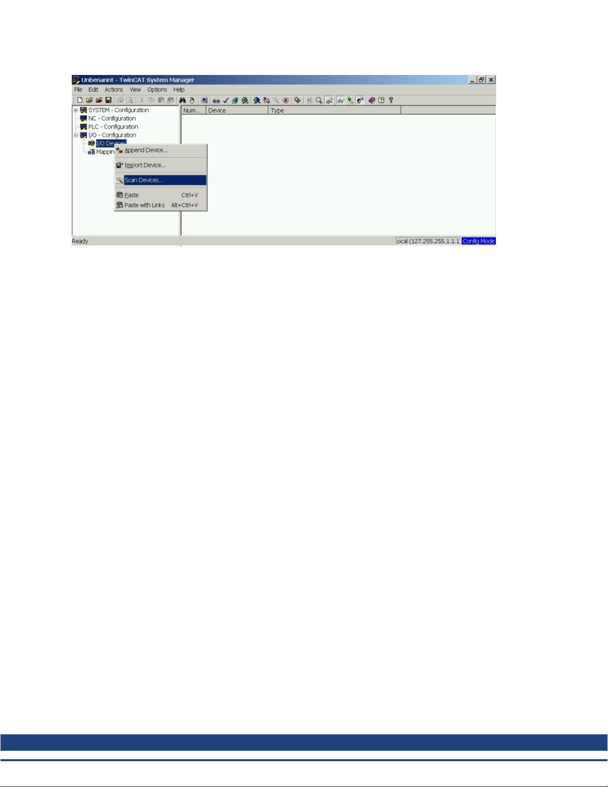
3.4.1 Scan devices
First ensure that the EtherCAT master is physically connected to the EtherCAT AKD Drive. Create a new
(empty) project. Right click I/O-Devices and scan for the devices. An example is included in the EtherCAT network card, which is plugged into the PC.
Kollmorgen | December 2009 15
Page 16
AKD EtherCAT | 3 Installation and Setup
A pop-up window informs you that not all devices can be detected by the TwinCAT software.
Click OK to continue.
16 Kollmorgen | December 2009
Page 17

AKD EtherCAT | 3 Installation and Setup
3.4.2 Select the device
TwinCAT must beableto findthe EtherCAT network card.An EtherCAT slave must beconnectedto the network
card; otherwise TwinCAT will find a real-timeEtherNET cardinsteadof theEtherCAT card. Press theOK button.
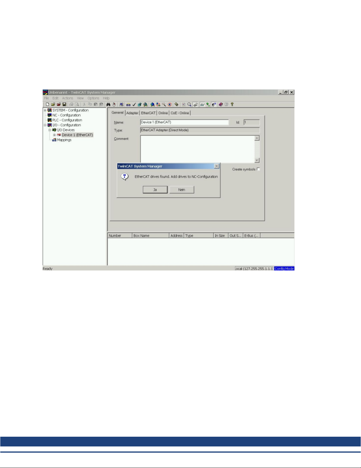
3.4.3 Scan for boxes
Click Yes to allow TwinCat to scan for boxes. A box is an alias for a slave device and is always used in Beckhoff software products.
Kollmorgen | December 2009 17
Page 18
AKD EtherCAT | 3 Installation and Setup
3.4.4 Add Slaves to NC tasks
TwinCAT should now have identified the AKD according to the Device Description file. TwinCAT next asks if
the slaves should be connected to NC tasks. Click Yes to continue. An NC task can, for example, contain a
PLC program, which can be programmed by the user.
18 Kollmorgen | December 2009
Page 19

AKD EtherCAT | 3 Installation and Setup
3.4.5 Enable the network configuration
Confirm that the AKD appears in the device tree. Next, enable the network configuration Press first the
button in order to generate the mappings, afterwards press the button in order to let TwinCAT check the
configuration and use finally the button in order to step into run-mode.
Confirm afterwards that TwinCAT is allowed to jump into run-mode.
Kollmorgen | December 2009 19
Page 20

AKD EtherCAT | 3 Installation and Setup
3.4.6 Enable the axis and move the axis
The Axis can be enabled by a mouse-click on the Set button within the Online window inside of each Axis, see
also the next picture.
Afterwards a pop-up window appears.
The following setting enables the drive and allows command values in both directions.
Afterwards the motor should move in positive or negative direction as soon as the clicks on the following yellow buttons within the Online window:
20 Kollmorgen | December 2009
Page 21

AKD EtherCAT | 4 EtherCAT Profile
4 EtherCAT Profile
4.1 Slave Register 22
4.2 AL Event (Interrupt Event) and Interrupt Enable 23
4.3 Phase Run-Up 25
4.4 CANopen over EtherCAT (CoE) Status Machine 27
4.5 Fixed PDO Mappings 30
4.6 Supported Cyclical Setpoint- and Actual Values 30
4.7 Supported Operation Modes 30
4.8 Adjusting EtherCAT Cycle Time 31
4.9 Maximum Cycle Times depending on operation mode 31
4.10 Synchronization 31
4.11 Latch Control Word and Latch Status Word 32
4.12 Mailbox Handling 33
4.13 Fieldbus Parameters 37
Kollmorgen | December 2009 21
Page 22

AKD EtherCAT | 4 EtherCAT Profile
4.1 Slave Register
The table below gives the addresses of individual registers in the FPGA memory. The data is provided in littleendian format, with the ’least significant byte’ occupying the lowest address. A detailed description of all registers and FPGA memory locations is available in the “EtherCAT Slave Controller” description of the EtherCAT user organization (www.EtherCAT.org).
Length
Address
0x0120 2 AL Control R/W R/O
0x0130 2 AL Status R/O R/W
0x0134 2 AL Status Code R/O R/W
0x0204 2 Interrupt Enable Register R/O R/W
0x0220 2 AL Event (IRQ Event) R/W R/O
0x0800 8 Sync Manager 0 (Mail Out Control Register) R/W R/O
0x0808 8 Sync Manager 1 (Mail In Control Register) R/W R/O
0x0810 8 Sync Manager 2 (Process data Output Control Register) R/W R/O
0x0818 8 Sync Manager 3 (Process data Input Control Register) R/W R/O
0x0820 8 Sync Manager 4 R/W R/O
0x0828 8 Sync Manager 5 R/W R/O
0x0830 8 Sync Manager 6 R/W R/O
0x0838 8 Sync Manager 7 R/W R/O
0x0840 8 Sync Manager 8 R/W R/O
0x1100 Max. 64 ProOut Buffer (Process data Output, setpoints ECAT) R/W R/O
0x1140 Max. 64 ProIn (Process data Input, act. values ECAT) R/O R/W
0x1800 512 Mail Out Buffer (Object Channel Buffer ECAT,
0x1C00 512 Mail In Buffer (Object Channel Buffer Drive,
(Byte) Description
byte-length is specified in the device description file)
byte-length is specified in the device description file)
ZA
ECAT*ZADrive*
R/W R/O
R/O R/W
* ZA ECAT = Access mode EtherCAT
* ZA Drive = Access mode Drive
22 Kollmorgen | December 2009
Page 23

AKD EtherCAT | 4 EtherCAT Profile
4.2 AL Event (Interrupt Event) and Interrupt Enable
Communication between the drive and the EtherCAT FPGA can be interrupt-driven. The interrupt enable register and the AL event register are responsible for the EtherCAT interface interrupt functionality.
There are two events which lead also to a HW interrupt within the Drive, the EEPROM emulation event and
the SyncManager 2 event. The actual values of the Drive (SyncManager 3 data) are written without any AL
event request during each HW IRQ, e.g. triggered by a SyncManager 2 event. The Mailbox exchange
between the master and the AKD is completely handled by polling the AL event register within the background
task of the Drive.
The drive activates individual EtherCAT interface events when the corresponding bit of the interrupt enable
register is set to 1. When it is set to 0, the hardware interrupts for the specific events are deactivated.
4.2.1 Interrupt Enable Register (Address 0x0204:0x0205)
Parameter Address BitZADriveZAECAT Description
AL Control Event 0x204 0 R/W R/O Activation of AL control event for phase run-up
- 0x204 1 R/W R/O Reserved
Sync0 DC Distributed
Clock
Sync1 DC Distributed
Clock
SyncManager activation
register change
EEPROM emulation
event
- 0x204 3 to 7 R/W R/O Reserved
Sync Manager 0 Event
(Mail Out Event)
Sync Manager 1 Event
(Mail In Event)
Sync Manager 2 Event
(Pro Out Event)
Sync Manager 3 Event
(Pro In Event)
- 0x205 4 to 7 R/W R/O Reserved
0x204 2 R/W R/O Activation of distributed clock (DC) sync 0 inter-
rupts for entire communication
0x204 3 R/W R/O Activation of distributed clock (DC) sync 1 inter-
rupts for entire communication
0x204 4 R/W R/O Activation of ‘SyncManager activation register
change’ IRQ.
0x204 5 R/W R/O Activation of the EEPROM emulation interrupts.
0x205 0 R/W R/O Activation of output event mailbox (SDO, Sync
Manager 0) for object channel.
0x205 1 R/W R/O Activation of input event mailbox (SDO, Sync Man-
ager 1) for object channel.
0x205 2 R/W R/O Activation of output event process data (PDO,
card's cyclical setpoints)
0x205 3 R/W R/O Activation of input event process data (PDO,
drive's cyclical actual values)
Kollmorgen | December 2009 23
Page 24

AKD EtherCAT | 4 EtherCAT Profile
4.2.2 AL Event Request (Address 0x0220:0x0221)
When the relevant bit of the AL event request register is set to 1, the EtherCAT interface tells the drive which
event it should process by the AKD.
Parameter Address BitZADriveZAECAT Description
AL Control Event 0x220 0 R/O R/W Processing of AL control event for phase run-
Sync0 Distributed
0x220 2 R/O R/W Processing of a distributed clock (DC) event
Clock (DC) Event
Sync1 Distributed
0x220 3 R/O R/W Processing of a distributed clock (DC) event
Clock (DC) Event
SyncManager acti-
0x220 4 R/O R/W The content of the SyncManager activation
vation register change
EEPROM emulation
0x220 5 R/O R/W Processing of an EEPROM emulation event in
event
- 0x220 6 to 7 R/O R/W Reserved
Sync Manager 0
0x221 0 R/O R/W Mailbox request (SDO, Sync Manager 0) for
Event
Sync Manager 1
0x221 1 R/O R/W Mailbox response (SDO, Sync Manager 1) for
Event
Sync Manager 2
0x201 2 R/O R/W Process data output (PDO, card's cyclical set-
Event
Sync Manager 3
0x201 3 R/O R/W Process data input (PDO, drive's cyclical
Event
Sync Manager 4 –
Sync Manager 7
0x221 4 to 7 R/O R/W Reserved
Event
Sync Manager 8 –
Sync Manager 15
0x222 0…7 R/O R/W Reserved
Event
up
register has been changed.
order to identify the AKD within the network.
object channel.
object channel.
points)
actual values)
24 Kollmorgen | December 2009
Page 25

AKD EtherCAT | 4 EtherCAT Profile
4.3 Phase Run-Up
The AL control, AL status and AL status code registers are responsible for communication phase run-up (also
referred to as EtherCAT status change), for current status display and for any fault messages. The drive
responds to every EtherCAT interface transition request made by the AL control register via the AL Status and
AL Status Code registers. Any fault messages are displayed in the AL status code register.
A status change within the AL control register is polled within the AKD, which means that an AL control event
does not lead to a HW interrupt within the Drive.
4.3.1 AL Control (Address 0x0120:0x0121)
Parameter Address BitZADriveZAECAT Description
Status 0x120 3 to 0 R/O W/O 0x01: Init Request
0x02: PreOperational Request
0x03: Bootstrap Mode Request
0x04: Safe Operational Request
0x08: Operational Request
Acknowledgement 0x120 4 R/O W/O 0x00: No fault acknowledgement
0x01: Fault acknowledgement (positive edge)
Reserved 0x120 7 to 5 R/O W/O Applic. specific 0x120 15 to 8 R/O W/O -
4.3.2 AL Status (Address 0x0130:0x0131)
Parameter Address BitZADriveZAECAT Description
Status 0x130 3 to 0 W/O R/O 0x01: Init
0x02: PreOperational
0x03: Bootstrap Mode
0x04: Safe Operational
0x08: Operational
Status change 0x130 4 W/O R/O 0x00: Acknowledgement
0x01: Error, e.g. forbidden transition
Reserved 0x130 7 to 5 W/O R/O Applic. specific 0x130 15 to 8 W/O R/O -
Kollmorgen | December 2009 25
Page 26

AKD EtherCAT | 4 EtherCAT Profile
4.3.3 AL Status Code (Address 0x0134:0x0135)
Parameter Address Bit ZA Drive ZA ECAT Description
Status 0x134 7 to 0 W/O R/O See table below
Status 0x135 7 to 0 W/O R/O See table below
Code Description
0x0000 No error All Current Status
0x0011 Invalid requested state change I -> S, I -> O, P -> O,
0x0017 Invalid sync manager configuration I -> P, P -> S Current Status + E
No other codes are supported.
4.3.4 EtherCAT communication phases
Current Status
(Status change) Resulting Status
Current Status + E
O -> B, S -> B, P -> B
INIT:
Initialization, no communication. EEPROM emulation will be activated.
PRE-OP:
Mailbox active, slave parameterization and startup parameters
SAVE-OP:
Cyclical actual values are transferred and the drive tries to synchronize.
OPERATIONAL:
Cyclical setpoints are processed, torque enable can be activated
and the drive must be synchronized.
Individual communication transitions
AL Control
Transition
(Bit 3 to 0) Description
(IB) 0x03 (BI) - (IP) 0x02 AKD reads the SyncManager 0 & 1 configuration and verifies the value of the start-
address and the length. The AKD prepares itself for handling SyncManager 0 events.
(PI) 0x01 -
(PS) 0x04 AKD reads the SyncManager 2 & 3 configuration and verifies the value of the start-
address and the length.
(SP) 0x02 -
(SI) 0x01 -
(SO) 0x08 The SnycManager 2 hardware interrupt will be enabled by the Drive.
(OS) 0x04 Deactivation of SyncManager 2 hardware interrupt.
(OP) 0x02 Deactivation of SyncManager 2 hardware interrupt..
(OI) 0x01 Deactivation of SyncManager 2 hardware interrupt.
26 Kollmorgen | December 2009
Page 27

AKD EtherCAT | 4 EtherCAT Profile
4.4 CANopen over EtherCAT (CoE) Status Machine
The status machine for the control and status words corresponds to the CANopen status machine in accordance with DS402. CANopen control and status words are captured in every instance of fixed PDO mapping
(see chapter entitled ‘Fixed PDO Mapping‘, page ).
4.4.1 Status Description
Status Description
Not Ready to SwitchOnThe drive is not ready to switch on; the controller has not indicated readiness for
service. The drive is still in the boot phase or in fault status.
Switch On Disable In 'Switch On Disable' status, the amplifier cannot be enabled via the EtherCAT
interface, because (for example) there is no connection to a power source.
Ready to Switch On In 'Ready to Switch On' status, the drive can be enabled via the control word.
Switched On In 'Switched On' status, the amplifier is enabled, but the setpoints of the EtherCAT-
interface are not yet transferred. The amplifier is idle, and a positive edge in bit 3 of
the control word activates setpoint transfer (transition to 'Operation Enable' status).
Operation Enable In this status, the drive is enabled and setpoints are transferred from the EtherCAT
interface.
Quick Stop Active The drive follows a quick stop ramp.
Fault Reaction Active The drive responds to a fault with an emergency stop ramp.
Fault A fault is pending, the drive is stopped and disabled.
Kollmorgen | December 2009 27
Page 28

AKD EtherCAT | 4 EtherCAT Profile
4.4.2 Commands in the Control Word
Bit assignment in the control word
Bit Name Bit Name
0 Switch on 8 Pause/halt
1 Disable Voltage 9 reserved
2 Quick Stop 10 reserved
3 Enable Operation 11 reserved
4 Operation mode specific 12 reserved
5 Operation mode specific 13 Manufacturer-specific
6 Operation mode specific 14 Manufacturer-specific
7 Reset Fault (only effective for faults) 15 Manufacturer-specific
Commands in the control word
Command
Bit 7
Fault Reset
Bit 3
Enable Operation
Bit 2
Quick Stop
Bit 1
Disable Voltage
Bit 0
Switch on Transitions
Shutdown X X 1 1 0 2, 6, 8
Switch on X X 1 1 1 3
Disable Voltage X X X 0 X 7, 9, 10, 12
Quick Stop X X 0 1 X 7, 10, 11
Disable Operation X 0 1 1 1 5
Enable Operation X 1 1 1 1 4, 16
Fault Reset 1 X X X X 15
Bits labeled X are irrelevant. 0 and 1 indicate the status of individual bits.
Mode-dependent bits in the control word
The following table shows the mode-dependent bits in the control word. Only manufacturer-specific modes are
supported at present. The individual modes are set by Object 6060h Modes of operation.
Operation mode No. Bit 4 Bit 5 Bit 6
Profile Position Mode (pp) 01h new_set_point change_set_
absolute/relative
immediately
Profile Velocity Mode (pv) 03h reserved reserved reserved
Profile Torque Mode (tq) 04h reserved reserved reserved
Homing Mode (hm) 06h homing_operation_start reserved reserved
Interpolated Position Mode (ip) 07h reserved reserved
Cyclic synchronous position mode 08h reserved reserved reserved
Description of the remaining bits in the control word
Bit 8: (Pause) If Bit 8 is set, then the drive halts (pauses) in all modes. The setpoints (speed for homing or jog-
ging, motion task number, setpoints for digital mode) for the individual modes are retained.
Bit 9,10: These bits are reserved for the drive profile (DS402).
Bit 13, 14, 15: These bits are manufacturer-specific, and reserved at present.
28 Kollmorgen | December 2009
Page 29

4.4.3 Status Machine Bits (status word)
Bit assignment in the status word
Bit Name Bit Name
0 Ready to switch on 8 Manufacturer-specific (reserved)
1 Switched on 9 Remote (always 1)
2 Operation enable 10 Target reached
3 Fault 11 Internal limit active
4 Voltage enabled 12 Operation mode specific (reserved)
5 Quick stop 13 Operation mode specific (reserved)
6 Switch on disabled 14 Manufacturer-specific (reserved)
7 Warning 15 Manufacturer-specific (reserved)
States of the status machine
AKD EtherCAT | 4 EtherCAT Profile
State
Bit 6
switch on
disable
Bit 5
quick
stop
Bit 3
fault
Bit 2
operation
enable
Bit 1
switched
on
Bit 0
ready to
switch on
Not ready to switch on 0 X 0 0 0 0
Switch on disabled 1 X 0 0 0 0
Ready to switch on 0 1 0 0 0 1
Switched on 0 1 0 0 1 1
Operation enabled 0 1 0 1 1 1
Fault 0 X 1 0 0 0
Fault reaction active 0 X 1 1 1 1
Quick stop active 0 0 0 1 1 1
Bits labeled X are irrelevant. 0 and 1 indicate the status of individual bits.
Description of the remaining bits in the status word
Bit 4: voltage_enabled The DC-link voltage is present if this bit is set.
Bit 7: warning There are several possible reasons for Bit 7 being set and this warning being produced. The rea-
son for this warning can be revealed by using the Object 20subindex manufacturer warnings.
Bit 9:remoteis always set to1, i.e.thedrivecan always communicate andbe influencedvia theRS232-interface.
Bit 10: target_reached This is set when the drive has reached the target position.
Bit 11: internal_limit_active This bit specifies that a movement was or is limited. In different modes, different
warnings cause the bit to be set.
Kollmorgen | December 2009 29
Page 30

AKD EtherCAT | 4 EtherCAT Profile
4.5 Fixed PDO Mappings
Various ready-to-use mappings can be selected for cyclic data exchange via SDO’s of the object 0x1C12 and
0x1C13. Using object 0x1C12 subindex 1 (Sync Manager 2 assignment), a fixed mapping for the cyclic command values can be set with the values 0x1701 … 0x1702. Using object 0x1C13 subindex 1 (Sync Manager 3
assignment), a fixed mapping for the cyclic actual values can be set via the data 0x1B01 … 0x1B02.
The following sequence describes how to select the fixed command value mapping 0x1701 via SDO’s:
1. SDO write access to object 0x1C12Sub0 Data:0x00
2. SDO write access to object 0x1C12Sub1 Data:0x1701
3. SDO write access to object 0x1C12Sub0 Data:0x01
The following fixed mappings are supported:
Position interface:
0x1701: Position command value (4 bytes), Control word (2 bytes), total (6 bytes)
0x1B01: Position actual value (4 bytes), Status word (2 bytes), total (6 bytes)
Velocity interface:
0x1702: Velocity command value (4 bytes), Control word (2 bytes), total (6 bytes)
0x1B02: Position actual value (4 bytes), Status word (2 bytes), total (6 bytes)
4.6 Supported Cyclical Setpoint- and Actual Values
Supported cyclical setpoint values
Name CANopen object number Data type Description
Position command value 0x60C1 sub 1 INT32 interpolation data record in IP-mode
Velocity command value 0x60FF sub 0 INT32
CANopen control-word 0x6040 Sub 0 UINT16 CANopen control word.
Supported cyclical actual values
Name CANopen object number Data type Description
Position actual value 0x6063 sub 0 INT32
Velocity actual value 0x606c sub 0 INT32
CANopen status-word 0x6041 Sub 0 UINT16 CANopen status word.
4.7 Supported Operation Modes
CANopen mode of operation AKD mode of operation Description
Profile velocity DRV.OPMODE 2
DRC.CMDSOURCE 1
Interpolated position DRV.OPMODE 2
DRV.CMDSOURCE 1
0x6060Sub0 Data: 3
In this mode of operation the EtherCAT master
sends cyclic velocity command values to the AKD.
0x6060Sub0 Data: 7
In this mode of operation the EtherCAT master
sends cyclic position command values to the AKD.
These command values are interpolated by the AKD
according to the fieldbus sample rate.
30 Kollmorgen | December 2009
Page 31

AKD EtherCAT | 4 EtherCAT Profile
4.8 Adjusting EtherCAT Cycle Time
The cycle time to be used in the drive for the cyclical setpoints and actual values can either be stored in the
FBUS.SAMPLEPERIOD parameter in the amplifier or configured in the startup phase.
This takes place via SDO mailbox access (see chapter) to CANopen objects 60C2 subindex 1 and 2.
Subindex 2, known as the interpolation time index, defines the power of ten of the time value (e.g. -3 means
10-3 or milliseconds) while subindex 1, known as interpolation time units, gives the number of units (e.g. 4
means 4 units).
If you wish to run a 2 ms cycle, this can be achieved by means of various combinations. For example,
Index = -3, Units = 2
or
Index = -4, Units = 20 etc.
The FBUS.SAMPLEPERIOD parameter is counted in multiples of 62.5us microseconds within the device.
This means, for example that 2 ms equates to FBUS.SAMPLEPERIOD value of 32.
4.9 Maximum Cycle Times depending on operation mode
The minimum cycle time for the drive is largely dependent on the drive configuration (second actual position
value encoder latch functionality enabled and so on)
Interface Cycle time AKD
Position ≥ 0.25 ms (≥ 250 µs)
Velocity ≥ 0.25 ms (≥ 250 µs)
Torque ≥ 0.25 ms (≥ 250 µs)
4.10 Synchronization
On all drives, the internal PLL is theoretically able to even out an average deviation of up to 4800 ppm in the
cycle time provided by the master. The Drive checks once per fieldbus cycle a counter within the Drive internal FPGA, which is cleared by a Sync0 (Distributed clock) event. Depending of the counter value, the Drive
extends or decrease the 62.5[µs] MTS signal within the Drive by a maximum of 300[ns].
The theoretical maximum allowed deviation can be calculated by using the following formula:
The synchronization functionality within the Drive can be enabled via setting bit 0 of the FBUS.PARAM02
parameter to high. Therefore FBUS.PARAM02 must be set to the value of 1. Furthermore the distributed clock
functionality must be enabled by the EtherCAT master in order to activate cyclic Sync0 events.
Kollmorgen | December 2009 31
Page 32

AKD EtherCAT | 4 EtherCAT Profile
4.11 Latch Control Word and Latch Status Word
Latch Control word (2 Byte)
Bit Value (bin) Value (hex) Description
0 00000000 00000001 xx01 Enable extern latch 1 (positive rise)
1 00000000 00000010 xx02 Enable extern latch 1 (negative rise)
2 00000000 00000100 xx04 Enable extern latch 2 (positive rise)
3 00000000 00001000 xx08 Enable extern latch 2 (negative rise)
4
5-7 Reserve
8-12 00000001 00000000 01xx Read external latch 1 (positive rise)
00000010 00000000 02xx Read external latch 1 (negative rise)
00000011 00000000 03xx Read external latch 2 (positive rise)
00000100 00000000 04xx Read external latch 2 (negative rise)
13-15 Reserve
Latch Status word (2 Byte)
Bit Value (bin) Value (hex) Description
0 00000000 00000001 xx01 External latch 1 valid (positive rise)
1 00000000 00000010 xx02 External latch 1 valid (negative rise)
2 00000000 00000100 xx04 External latch 2 valid (positive rise)
3 00000000 00001000 xx08 External latch 2 valid (negative rise)
4
5-7 Reserve
8-11 00000001 00000000 X1xx Acknowledge value external latch 1 (positive rise)
00000010 00000000 X2xx Acknowledge value external latch 1 (negative rise)
00000011 00000000 X3xx Acknowledge value external latch 2 (positive rise)
00000100 00000000 X4xx Acknowledge value external latch 2 (negative rise)
12-15 00010000 00000000 1xxx Zustand Digital Input 4
00100000 00000000 2xxx Zustand Digital Input 3
01000000 00000000 4xxx Zustand Digital Input 2
10000000 00000000 8xxx Zustand Digital Input 1
32 Kollmorgen | December 2009
Page 33

AKD EtherCAT | 4 EtherCAT Profile
4.12 Mailbox Handling
With EtherCAT, acyclical data traffic (object channel or SDO channel) is called mailbox. This system is
based around the master:
Mailbox Output:
The master (EtherCAT controller) sends data to the slave (drive). This is essentially a (read/write) request
from the master. Mailbox output operates via Sync Manager 0.
Mailbox Input:
The slave (drive) sends data to the master (EtherCAT controller). The master reads the slave's response. Mailbox input operates via Sync Manager 1.
Timing diagram
The timing diagram illustrates the mailbox access process:
1. The EtherCAT master writes the mailbox request to the mail-out buffer.
2. On the next interrupt, the EtherCAT interface activates a Sync Manager 0 event (mailbox output event)
in the AL event register.
3. The drive reads 16 bytes from the mail-out buffer and copies them to the internal mailbox output array.
4. The drive identifies new data in the internal mailbox output array and performs an SDO access to the
object requested by the EtherCAT interface. The response from the drive is written to an internal mailbox input array.
5. The drive deletes all data in the internal mailbox output array so that a new mailbox access attempt can
be made.
6. The drive copies the response telegram from the internal mailbox input array to the mail-in buffer of the
EtherCAT interface.
Kollmorgen | December 2009 33
Page 34

AKD EtherCAT | 4 EtherCAT Profile
4.12.1 Mailbox Output
An interrupt by the EtherCAT-interface with a Sync Manager 0 - Event starts a Mailbox Output Process. A 1 in
the Mail Out Event-Bit of the AL Event register signalizes the drive, that the EtherCAT-interface wants to send
a Mailbox message and that it has already stored the required data in the Mail Out Buffer. Now 16 Byte data
are read by the drive with the IRQ process. The bytes are defined as follows
Address 0x1800 Address 0x180F
0 1 2 3 4 5 6 7 8 9 10 11 12 13 14 15
CAN over EtherCAT specific data
(CoE Header)
Byte 0 Length of the data (Low Byte)
Byte 1 Length of the data (High Byte)
Byte 2 Address (Low Byte)
Byte 3 Address (High Byte)
Byte 4 Bit 0 to 5: Channel
Bit 6 to 7: Priority
Byte 5 Bit 0 to 3: Type 1 = Reserved: ADS over EtherCAT
Bit 4 to 7: Reserved
Byte 6 PDO Number (with PDO transmissions only, Bit 0 = LSB of the PDO number, see Byte 7 for MSB)
Byte 7 Bit 0: MSB of the PDO number, see Byte 6
Bit 1 to 3: Reserved
Bit 4 to 7: CoE specific type 0: Reserved
Byte 8 Control-Byte in the CAN telegram:
write access: 0x23=4Byte, 0x27=3Byte, 0x2B=2Byte, 0x2F=1Byte
read access: 0x40
Byte 9 Low Byte of the CAN object number (Index)
Byte 10 High Byte of the CAN object number (Index)
Byte 11 Subindex according to CANopen Specification for the drive
Byte 12 Data with a write access (Low Byte)
Byte 13 Data with a write access
Byte 14 Data with a write access
Byte 15 Data with a write access (High Byte)
CAN specific data
(standard CAN SDO)
2 = Reserved: Ethernet over EtherCAT
3 = Can over EtherCAT…)
1: Emergency message
2: SDO request
3: SDO answer
4: TXPDO
5: RxPDO
6: Remote transmission request of a TxPDO
7: Remote transmission request of a RxPDO
8…15: reserved
The drive answers every telegram with an answer in the Mailbox Input buffer.
34 Kollmorgen | December 2009
Page 35

AKD EtherCAT | 4 EtherCAT Profile
4.12.2 Mailbox Input
The drive answers every CoE telegram with a 16 byte answer telegram in the Mailbox Input buffer. The bytes
are defined as follows:
Address 0x1C00 Address 0x1C0F
0 1 2 3 4 5 6 7 8 9 10 11 12 13 14 15
CAN over EtherCAT specific data
(CoE Header)
CAN specific data
(standard CAN SDO)
Byte 0 Length of the data (Low Byte)
Byte 1 Length of the data (High Byte)
Byte 2 Address (Low Byte)
Byte 3 Address (High Byte)
Byte 4 Bit 0 to 5: Channel
Bit 6 to 7: Priority
Byte 5 Bit 0 to 3: Type 1 = Reserved: ADS over EtherCAT
2 = Reserved: Ethernet over EtherCAT
3 = Can over EtherCAT…)
Bit 4 to 7: Reserved
Byte 6 PDO Number (with PDO transmissions only, Bit 0 = LSB of the PDO number, see Byte 7 for MSB)
Byte 7 Bit 0: MSB of the PDO number, see Byte 6
Bit 1 to 3: Reserved
Bit 4 to 7: CoE specific type 0: Reserved
1: Emergency message
2: SDO request
3: SDO answer
4: TXPDO
5: RxPDO
6: Remote transmission request of a TxPDO
7: Remote transmission request of a RxPDO
8…15: reserved
Byte 8 Control-Byte in the CAN telegram:
write access OK: 0x60
read access OK + length of answer: 0x43 (4 Byte), 0x47 (3 Byte), 0x4B (2Byte), 0x4F (1Byte)
error with read- or write access: 0x80
Byte 9 Low Byte of the CAN object number (Index)
Byte 10 High Byte of the CAN object number (Index)
Byte 11 Subindex according to CANopen Specification for Kollmorgen drive
Byte 12 Data (Low Byte)
Byte 13 Data error code Fehlercode according to CANopen Specification in
case of an error
Byte 14 Data data value of the object in case of successfull read access
Byte 15 Data (High Byte)
Kollmorgen | December 2009 35
Page 36

AKD EtherCAT | 4 EtherCAT Profile
4.12.3 Example: Mailbox Access
In the example below, PDOs 0x1704 are mapped (see Chapter # “Fixed PDO Mappings”):
The master sends this mailbox output message:
Byte 0 0x0A The next 10 Bytes contain data (Byte 2 to Byte 11)
Byte 1 0x00 The next 10 Bytes contain data (Byte 2 to Byte 11)
Byte 2 0x00 Address 0
Byte 3 0x00 Address 0
Byte 4 0x00 Channel 0 and Priority 0
Byte 5 0x03 CoE Object
Byte 6 0x00 PDO Number 0
Byte 7 0x20 PDO Number 0 and SDO-Request
Byte 8 0x2B 2 Byte write access
Byte 9 0x12 SDO-Object 0x1C12
Byte 10 0x1C SDO-Object 0x1C12
Byte 11 0x01 Subindex 1
Byte 12 0x04 Data value 0x00001704
Byte 13 0x17 Data value 0x00001704
Byte 14 0x00 Data value 0x00001704
Byte 15 0x00 Data value 0x00001704
The drive returns the following message:
Byte 0 0x0E The next 14 Bytes contain data (Byte 2 to Byte 15)
Byte 1 0x00 The next 14 Bytes contain data (Byte 2 to Byte 15)
Byte 2 0x00 Address 0
Byte 3 0x00 Address 0
Byte 4 0x00 Channel 0 and Priority 0
Byte 5 0x03 CoE Object
Byte 6 0x00 PDO Number 0
Byte 7 0x20 PDO Number 0 and SDO-Answer
Byte 8 0x60 Successful write access
Byte 9 0x12 SDO-Object 0x1C12
Byte 10 0x1C SDO-Object 0x1C12
Byte 11 0x01 Subindex 1
Byte 12 0x00 Data value 0x00000000
Byte 13 0x00 Data value 0x00000000
Byte 14 0x00 Data value 0x00000000
Byte 15 0x00 Data value 0x00000000
36 Kollmorgen | December 2009
Page 37

AKD EtherCAT | 4 EtherCAT Profile
4.13 Fieldbus Parameters
The AKD Drive holds several fieldbus specific general purpose parameter. Some of them contain the following
EtherCAT relevant data:
FBUS.PARAM02: This parameter activates the synchronization feature of the AKD. The DC feature must be
activated in order to allow the AKD to get synchronized with the master. A value of 1 enables the Drive internal PLL functionality, a value of 0 deactivates this feature.
FBUS.PARAM03: This parameter contains the Configured Station Alias address of the AKD. An EEPROM
emulation write access to the Configured Station Alias address forces the AKD to store the Drive parameters
automatically via a DRV.NVSAVE command.
Kollmorgen | December 2009 37
Page 38

This page intentionally left blank.
38 Kollmorgen | December 2009
Page 39

5 Index
A
Abbreviations 8
AL Event 23
C
CANopen over EtherCAT 27
E
EtherCAT Proflie 21
I
Interrupt Event 23
AKD EtherCAT | 5 Index
P
Phase run-up 25
Prohibited Use 11
S
Safety Instructions
Electrical Installation 13
General 10
Slave Register 22
Symbols used 7
T
Target group 6
TwinCAT 15
U
Use as directed 11
Kollmorgen | December 2009 39
Page 40

This page intentionally left blank.
40 Kollmorgen | December 2009
Page 41

AKD EtherCAT |
This page intentionally left blank
Kollmorgen | December 2009 41
Page 42

AKD EtherCAT |
Sales and Service
We are committed to quality customer service. Inorder to serve in the most effective way, please contact
yourlocal sales representative for assistance.
If you are unaware of your local sales representative, pleasecontact us.
Europe
Kollmorgen Customer Support Europe
Internet www.kollmorgen.com
E-Mail technik@kollmorgen.com
Tel.: +49(0)203 - 99 79 - 0
Fax: +49(0)203 - 99 79 - 155
North America
Kollmorgen Customer Support North America
Internet www.kollmorgen.com
E-Mail support@kollmorgen.com
Tel.: +1 - 540 - 633 - 3545
Fax: +1 - 540 - 639 - 4162
Kollmorgen | December 2009 42
 Loading...