

Kollmorgen AKD series, AKD BASIC series, AKD PDMM series Installation Manual

AKD®, AKD
®
BASIC, AKD
Installation Manual
®
PDMM
Edition: AA, October 2017
Valid for AKD, AKD BASIC HardwareRevision E
Valid for AKD BASIC-I/O Hardware Revision EA
Valid for AKD PDMM Hardware Revision EB
Part Number 903-200003-00
Original Document
Keep allmanuals as a product component during the life span of the product. Passallmanuals to
future users and owners of the product.
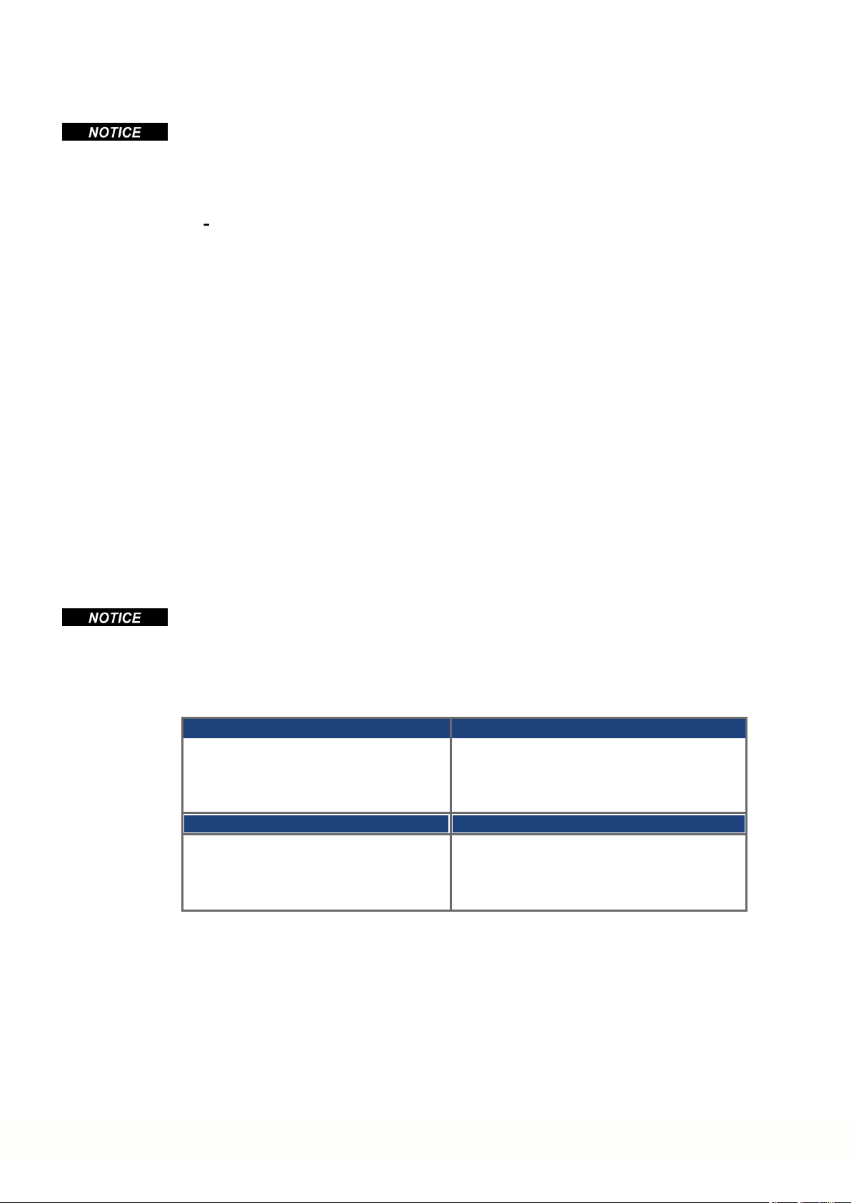
Record of Document Revisions
Revision Remarks
...
Table with lifecycle information of this document see (➜ # 215)
Techn.Data X7 (Electr.Gearing)updated, LV and EMC Directive version updated, Warning
W, 08/2016
notes updated, chapterHandling moved, 48A motor brake connection corrected, PFH value
changed
Y, 03/2017
AA, 10/2017
Frequency limit EnDat 2.2 changed, Links in Fault chapters to KDN, fault tableupdated (F120,
F124, n179, n180, F471, n495, F631)
Digital output wiring X23/X24 updated, STO reaction time added (03...24A), 24V wiringfor 48A
STO control, AKD48A motor holding brake connection corrected
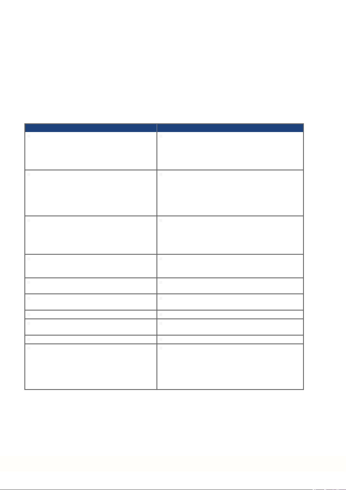
Hardware Revision (HR)
AKD-
B/P-NA
A - -
C - -
AKD-
B/P-NB
AKD-MAKD-
T-IC
-
-
Firmware/
Workbench
KAS IDE
Export
Classification
Remarks
from 1.3 - 3A225 Start revision, export control
from 1.5 - 3A225
STO certified, PROFINET RT
released, export control
Control board revision 9, AKD
- D DB
DA
from 1.6 from 2.5 3A225
PDMM Start revision, AKD
BASIC-IC Start revision,
export control
Hardware revision for export
D E EB
EA
from 1.13 from 2.9 -
classification tracebility purposes
Trademarks
AKD is a registered trademark of Kollmorgen Corporation
EnDat is a registered trademark of Dr. Johannes HeidenhainGmbH
EtherCAT is a registered trademark and patented technology, licensed by Beckhoff Automation GmbH
Ethernet/IP is a registered trademark of ODVA, Inc.
Ethernet/IP Communication Stack: copyright (c) 2009, Rockwell Automation
sercos®is a registered trademark of sercos®international e.V.
HIPERFACE is a registeredtrademark of Max Stegmann GmbH
PROFINET is a registered trademark of PROFIBUS and PROFINET International (PI)
SIMATIC is a registered trademark of SIEMENS AG
Windows is a registered trademark of Microsoft Corporation
Current patents
US Patent 8,154,228 (Dynamic Braking For Electric Motors)
US Patent 8,214,063 (Auto-tune of a Control System Based on Frequency Response)
Patents referring to fieldbus functions are listed in the matching fieldbus manual.
Technical changes which improve the performance of the device may be made without prior notice!
This document is the intellectual property of Kollmorgen. All rights reserved. No part of this work may be reproduced in any form (by photocopying, microfilm or any other method)or stored, processed, copied or distributed
by electronic means without the written permission of Kollmorgen.
2 Kollmorgen | kdn.kollmorgen.com | October 2017

AKD Installation | Table of Contents
1 Table of Contents
1 Table of Contents 3
2 General 9
2.1 About thisInstallation Manual 10
2.2 Using the PDF Format 10
2.3 SymbolsUsed 11
2.4 AbbreviationsUsed 12
2.5 Referred Standards 13
3 Safety 14
3.1 You should payattention to this 15
3.2 Use asDirected 17
3.3 Prohibited Use 18
3.4 Warning notes placed on the product 18
4 Handling 19
4.1 Transport 20
4.2 Packaging 20
4.3 Storage 20
4.4 Decommissioning 21
4.5 Maintenance and cleaning 21
4.6 Disassemble 21
4.7 SystemRepair 22
4.8 Disposal 22
5 Approvals 23
5.1 Conformance withUL/cUL 24
5.1.1 UL Markings/ Marquages UL 24
5.2 Conformance withCE 26
5.2.1 European Directivesand Standards for the Machine Builder 27
5.2.2 Conformance with RoHS 27
5.2.3 Conformance with REACH 27
5.3 Safe Torque Off (STO) approval 28
5.4 Conformance withEAC 28
6 Package 29
6.1 PackageSupplied 30
6.2 Nameplate 30
6.3 Part Number Scheme 31
7 Technical description and data 32
7.1 The AKD Familyof DigitalDrives 33
7.2 Ambient Conditions, Ventilation, and Mounting Position 35
7.3 MechanicalData 35
7.4 Inputs/Outputs 36
7.5 Electrical Data AKD-xzzz06 37
7.6 Electrical Data AKD-xzzz07 38
7.7 Performance Data 39
7.8 Recommended Tightening Torques 39
7.9 Grounding System 39
7.10 Fusing 40
7.10.1 External power supplyfusing 40
7.10.2 External 24 V supply fusing 40
7.10.3 External regen resistor fusing 40
7.10.4 External DC Buslinkfusing 40
7.11 Connectors 41
Kollmorgen | kdn.kollmorgen.com | October 2017 3

AKD Installation | Table of Contents
7.12 Cable and Wire Requirements 42
7.12.1 General 42
7.12.2 Cable cross sections and requirements 42
7.13 Dynamic Braking 43
7.13.1 Regen circuit 43
7.13.2 Functional description 43
7.13.3 Technicaldata for AKD-xzzz06 44
7.13.4 Technicaldata for AKD-xzzz07 45
7.14 Switch-On and Switch-Off Behavior 46
7.14.1 Switch-on behavior in standard operation 47
7.14.2 Switch-off behavior 48
7.14.2.1 Switch-off behavior using the DRV.DIS command 48
7.14.2.2 Switch-off behavior using a digitalinput (controlled stop) 49
7.14.2.3 Switch-off behavior using HW Enableinput (uncontrolled stop) 49
7.14.2.4 Switch-off behavior in the event of a fault 50
7.15 Stop / Emergency Stop / Emergency Off 53
7.15.1 Stop 53
7.15.2 Emergency Stop 54
7.15.3 Emergency Off 54
7.16 Safe Torque Off (STO) 55
7.16.1 Safety characteristicdata 55
7.16.2 Safety instructions 56
7.16.3 Use as directed 57
7.16.4 Prohibited use 57
7.16.5 Technicaldata and pinout 57
7.16.6 Enclosure, wiring 59
7.16.7 OSSD test pulses 59
7.16.8 Functional description 60
7.16.8.1 Signal diagram (sequence) 61
7.16.8.2 Wiring examples 62
7.16.8.3 Functional test 64
7.17 Shock-hazard Protection 66
7.17.1 Leakage current 66
7.17.2 Residualcurrent protectivedevice(RCD) 66
7.17.3 Isolating transformers 66
8 Mechanical Installation 67
8.1 Important Notes 68
8.2 Guide to MechanicalInstallation 68
8.3 MechanicalDrawings Standard Width 69
8.3.1 Control cabinetlayout AKD-xzzz06, standard width 69
8.3.2 Control cabinetlayout AKD-xzzz07, standard width 70
8.3.3 DimensionsAKD-xzzz06,standard width 71
8.3.4 DimensionsAKD-xzzz07,standard width 72
8.4 MechanicalDrawings Extended Width 73
8.4.1 Control cabinetlayout, example withAKD-M00306 73
8.4.2 Control cabinetlayout, example withAKD-M00307 74
8.4.3 DimensionsAKD-xzzz06,extended width 75
8.4.4 DimensionsAKD-xzzz07,extended width 76
9 Electrical Installation 77
9.1 Important Notes 78
9.2 Guide to electricalinstallation 79
9.3 Wiring 80
9.4 Components of aservosystem 81
9.5 Connection Overview AKD-B, AKD-P, AKD-T 83
4 Kollmorgen | kdn.kollmorgen.com | October 2017

AKD Installation | Table of Contents
9.5.1 Connector assignment AKD-x00306, AKD-x00606 83
9.5.2 Connection diagram AKD-x00306, AKD-x00606 84
9.5.3 Connector assignment AKD-x01206 85
9.5.4 Connection diagram AKD-x01206 86
9.5.5 Connector assignment AKD-x02406 and AKD-x00307 to 02407 87
9.5.6 Connection diagram AKD-x02406 and AKD-x00307 to 02407 88
9.5.7 Connector assignment AKD-x04807 89
9.5.8 Connection diagram AKD-x04807 90
9.6 Connection Overview AKD-M 91
9.6.1 Connector assignment AKD-M00306, AKD-M00606 91
9.6.2 Connection diagram AKD-M00306, AKD-M00606 92
9.6.3 Connector assignment AKD-M01206 93
9.6.4 Connection diagram AKD-M01206 94
9.6.5 Connector assignment AKD-M02406, AKD-M00307 to AKD-M02407 95
9.6.6 Connection diagram AKD-M02406, AKD-M00307 to AKD-M02407 96
9.6.7 Connector assignment AKD-M04807 97
9.6.8 Connection diagram AKD-M04807 98
9.7 EMI Noise Reduction 99
9.7.1 Recommendations for EMI noisereduction 99
9.7.2 Shielding with external shielding busbar 100
9.7.2.1 ShieldingConcept 100
9.7.2.2 ShieldingBusbar 101
9.7.3 Shielding connection to the drive 102
9.7.3.1 Grounding plates 102
9.7.3.2 Shield connection clamps 102
9.7.3.3 Motor connector X2 with shielding connection 102
9.8 Electrical Supply Connection 103
9.8.1 Connection to various mainssupply networks AKD-xzzz06 (120V to 240V) 103
9.8.2 Connection to various mainssupply networks AKD-xzzz07 (240V to 480V) 104
9.8.3 24 V auxiliary supply (X1) 105
9.8.3.1 AKD-x003 to 024, connector X1 105
9.8.3.2 AKD-x048, connector X1 105
9.8.4 Mainssupplyconnection (X3, X4) 106
9.8.4.1 Three phase connection (allAKD types) 107
9.8.4.2 Single/Dual phase connection(AKD-x00306 to AKD-x01206 only) 107
9.9 DC Bus link (X3, X14) 108
9.9.1 DC Bustopology withY connectors (24 A max.) 109
9.9.2 DC Bustopology withbusbar 109
9.9.3 External regen resistor (X3) 110
9.9.3.1 AKD-x003 to 024, regen connector X3 110
9.9.3.2 AKD-x048, regen connector X3 111
9.9.4 Capacitor Modules(X3) 112
9.9.4.1 Technical Data 112
9.9.4.2 Example installationwith KCM-S and KCM-E 113
9.9.4.3 Example installationwith KCM-P and KCM-E 114
9.9.4.4 Discharging KCM modules 115
9.10 Motor Power Connection(X2) 116
9.10.1 AKD-x003 to 024, power connector X2 117
9.10.2 AKD-x048, power connector X2 117
9.11 Motor Brake Connection (X2, X15, X16) 118
9.11.1 AKD-x003 to 024, bBrake connector X2 118
9.11.2 AKD-x048, brake connectors X15, X16 119
9.11.3 Functionality 120
9.12 Feedback Connection (X10, X9, X7) 121
Kollmorgen | kdn.kollmorgen.com | October 2017 5

AKD Installation | Table of Contents
9.12.1 Feedback connector (X10) 122
9.12.2 Feedback connector (X9) 123
9.12.3 Feedback connector (X7) 123
9.12.4 Resolver 124
9.12.5 SFD 125
9.12.6 SFD3 126
9.12.7 Hiperface DSL 127
9.12.8 Encoder with BiSS 128
9.12.8.1 BiSS (Mode B) analog 128
9.12.8.2 BiSS (Mode C) digital 129
9.12.9 SineEncoder with EnDat 2.1 130
9.12.10 Encoder with EnDat 2.2 131
9.12.10.1 Connectionto X10 131
9.12.10.2 Connectionto X9 and X8 132
9.12.11 Sine Encoder with Hiperface 133
9.12.12 Sine Encoder 134
9.12.13 Incremental Encoder 135
9.12.14 HallSensors 136
9.12.15 Tamagawa Smart AbsEncoder 137
9.13 Electronicgearing, Master-slave operation (X9, X7) 138
9.13.1 Technicalcharacteristicsand pinout 138
9.13.1.1 Connector X7 Input 138
9.13.1.2 Connector X9 Input 139
9.13.1.3 Connector X9 Output 139
9.13.2 Command encoder signalconnection 140
9.13.2.1 Incremental encoder input 5 V (X9) 140
9.13.2.2 Incremental encoder input 24 V (X7) 140
9.13.2.3 Encoder with EnDat 2.2 input 5 V (X9) 141
9.13.3 Pulse / Directionsignal connection 142
9.13.3.1 Pulse / Direction input 5 V (X9) 142
9.13.3.2 Pulse / Direction Input 5 V to 24 V (X7) 142
9.13.4 CW /CCW signal connection 143
9.13.4.1 CW / CCW input 5 V (X9) 143
9.13.4.2 CW / CCW input 24 V (X7) 143
9.13.5 Emulated Encoder Output (EEO) 144
9.13.6 Master-Slave control 145
9.14 I/O Connection 146
9.14.1 Overview 146
9.14.1.1 I/O connectors X7 and X8 (allAKD variants) 146
9.14.1.2 I/O connectors X21, X22, X23 and X24(AKD-T with I/O option card only) 147
9.14.1.3 I/O connectors X35 and X36 (AKD-M only) 149
9.14.2 Analog Input (X8, X24) 150
9.14.3 Analog Output (X8, X23) 151
9.14.4 DigitalInputs (X7/X8) 152
9.14.4.1 Digital Inputs 1 and 2 153
9.14.4.2 Digital Inputs 3 to 7 154
9.14.4.3 Digital Input 8(ENABLE) 154
9.14.5 DigitalInputs with I/O option (X21, X22) 154
9.14.6 DigitalInputs (X35/X36) with AKD-M 157
9.14.7 DigitalOutputs (X7/X8) 159
9.14.7.1 Digital Outputs 1 and 2 159
9.14.7.2 FAULT relay contacts 160
9.14.8 DigitalOutputs with I/Ooption (X23/X24) 161
9.14.9 DigitalOutputs 21 to 24, 26 to 29 161
6 Kollmorgen | kdn.kollmorgen.com | October 2017

AKD Installation | Table of Contents
9.14.10 DigitalRelay Outputs 25, 30 163
9.14.11 DigitalOutputs (X35/X36) with AKD-M 164
9.14.11.1 Digital Outputs 21 and 22 164
9.15 LED display 165
9.16 Rotary Switches (S1, S2, RS1) 166
9.16.1 Rotary switches S1 and S2 with AKD-B, -P, -T 166
9.16.2 Rotary switch RS1 with AKD-M 166
9.17 Push-buttons (B1, B2,B3) 167
9.17.1 Push-button B1 with AKD-B, -P, -T 167
9.17.2 Push-buttons B1,B2, B3 with AKD-M 168
9.18 SD Card Slot 169
9.18.1 SD Card Slotwith I/O option card 169
9.18.2 SD Card Slotwith AKD-M 170
9.19 ServiceInterface (X11, X32) 171
9.19.1 Pinout X11, X32 171
9.19.2 ServiceBus ProtocolsX11, X32 171
9.19.3 PossibleNetwork Configurations 171
9.19.4 Setting the IP AddressAKD-B, AKD-P, AKD-T 172
9.19.5 Setting the IP AddressAKD-M 174
9.19.6 Modbus TCP 175
9.20 CAN-Bus Interface (X12/X13) 175
9.20.1 CAN-Bus activation with AKD-CC models 176
9.20.2 Baud rate for CAN-Bus 177
9.20.3 Node Address for CAN-Bus 178
9.20.4 CAN-Bus Termination 178
9.20.5 CAN-Bus Cable 178
9.20.6 CAN-Bus Wiring 179
9.21 Motion BusInterface (X5/X6/X11) 180
9.21.1 Pinout X5, X6, X11 180
9.21.2 BusProtocolsX5, X6,X11 180
9.21.3 EtherCAT 181
9.21.3.1 EtherCAT activation with AKD-CC models 181
9.21.4 SynqNet 182
9.21.5 PROFINET 182
9.21.6 Ethernet/IP 182
9.21.7 sercos® III 183
10 Setup 184
10.1 Important Notes 185
10.2 SetupAKD-B, AKD-P, AKD-T 186
10.2.1 Setup software WorkBench 186
10.2.2 Use as directed 186
10.2.3 Software description 187
10.2.4 Hardware requirements 187
10.2.5 Operating systems 187
10.2.6 Installation under Windows 2000/XP/VISTA/7 188
10.2.7 InitialDrive TestAKD-B, AKD-P, AKD-T 189
10.2.7.1 Unpacking, mounting,and wiring the AKD 189
10.2.7.2 Minimum wiring for drivetest without load 189
10.2.7.3 Set IP address 190
10.2.7.4 Confirm connections 190
10.2.7.5 Installand start WorkBench 191
10.2.7.6 Set drive IP address in WorkBench 191
10.2.7.7 Enable the drive using the setup wizard 191
10.3 Setup AKD-M 192
Kollmorgen | kdn.kollmorgen.com | October 2017 7

AKD Installation | Table of Contents
10.3.1 Setup software KASIDE 192
10.3.2 Use as directed 192
10.3.3 Software description 193
10.3.4 Hardware requirements 193
10.3.5 Operating systems 193
10.3.6 Installation under Windows XP/7 194
10.3.7 InitialDrive Test AKD-M 195
10.3.7.1 Unpacking, mounting,and wiring the AKD PDMM 195
10.3.7.2 Minimum wiring for drivetest without load 195
10.3.7.3 Set IP address 196
10.3.7.4 Confirm connections 196
10.3.7.5 Installand start KASIDE 197
10.3.7.6 Set drive IP address in KASIDE 198
10.3.7.7 Starting new project 199
10.4 Fault and Warning Messages 202
10.4.1 Fault and warning messagesAKD 202
10.4.2 Additionalfault messagesAKD-T 207
10.4.3 Additionalerror and alarm messagesAKD-M 208
10.4.3.1 Alarms 208
10.4.3.2 Errors 209
10.5 Troubleshooting the AKD 210
11 Index 211
12 Record of document revisions 215
8 Kollmorgen | kdn.kollmorgen.com | October 2017

AKD Installation | 2 General
2 General
2.1 About this Installation Manual 10
2.2 Using the PDF Format 10
2.3 Symbols Used 11
2.4 Abbreviations Used 12
2.5 Referred Standards 13
Kollmorgen | kdn.kollmorgen.com | October 2017 9
AKD Installation | 2 General
2.1 About this Installation Manual
This manual, AKD Installation Manual ("Instructions Manual" according to EC Machinery Dir-
ective 2006/42/EC), describes theAKD series of digital drives drive and includes information
needed to safely install an AKD. A digital version of this installationmanual (pdf format) is
available on theDVD included with yourdrive. Manual updates can be downloadedfrom the
Kollmorgen website (www.kollmorgen.com).
Additional documents includethe following:
WorkBench Online Help: : describes how to use your drive in common applications. It
also provides tips for maximizing your system performance with the AKD. The Online
Help includes the Parameter and Command Reference Guide which provides information
for the parameters and commands used to program the AKD.
CAN-BUS Communication: describes how to use your drive in CANopen applications.
EtherCAT Communication: describes how to use yourdrive in EtherCAT applications.
Ethernet/IP Communication: describes how to use your drive in Ethernet/IP applications.
sercos®III Communication: describes how to use your drive in sercos®applications.
PROFINET RT Communication: describes how to use your drive in PROFINET RT
applications.
SynqNet Communication: describes how to use your drive in SynqNet applications.
Accessories Manual.It provides information for accessories like cables and regen res-
istors used with AKD. Regional variants of this manual exist.
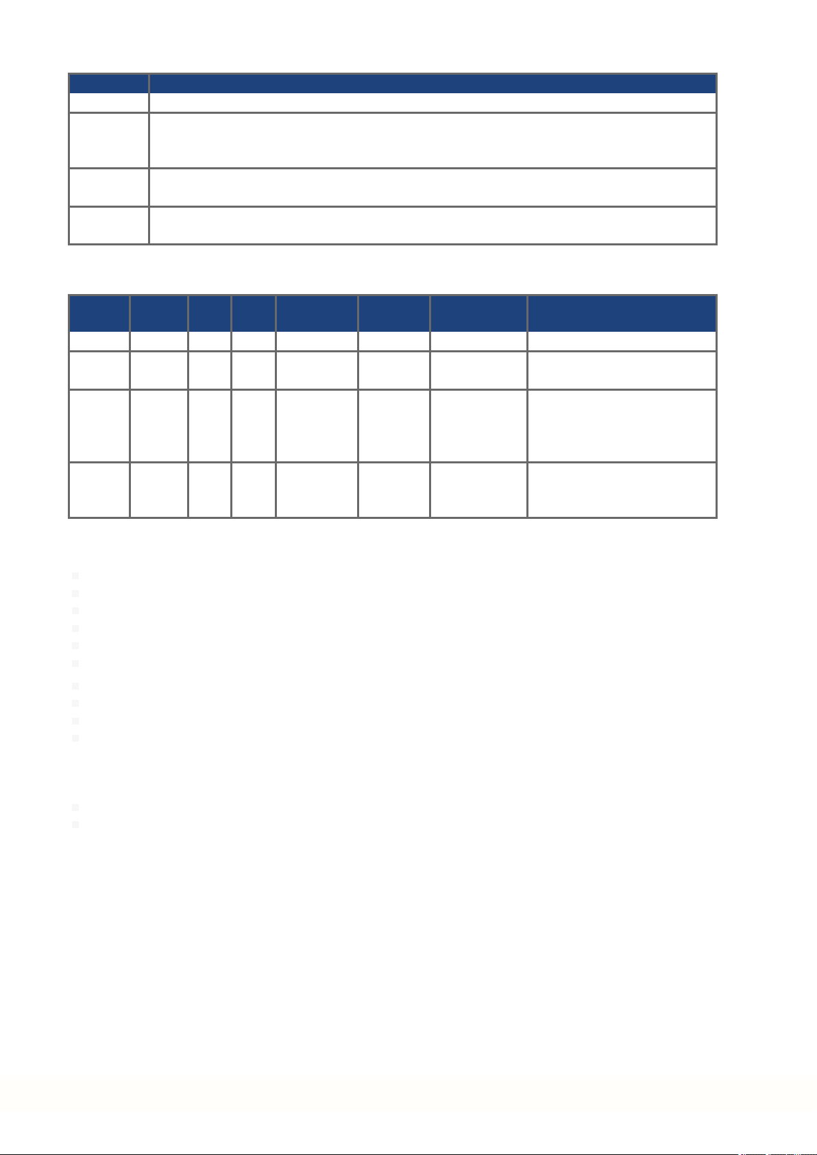
2.2 Using the PDF Format
This document includes several features for ease of navigation
Cross References Table of contents andindex include active cross references.
Table of contents and
index
Page/chapter numbers
in the text
Lines are active cross references. Click on the line and the appropriate page is accessed.
Page/chapternumbers with cross references areactive links.
10 Kollmorgen | kdn.kollmorgen.com | October 2017
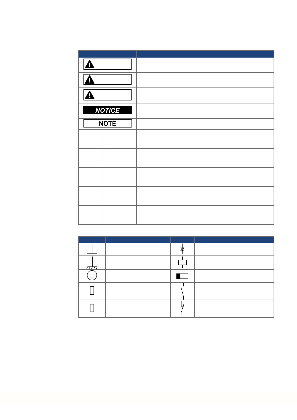
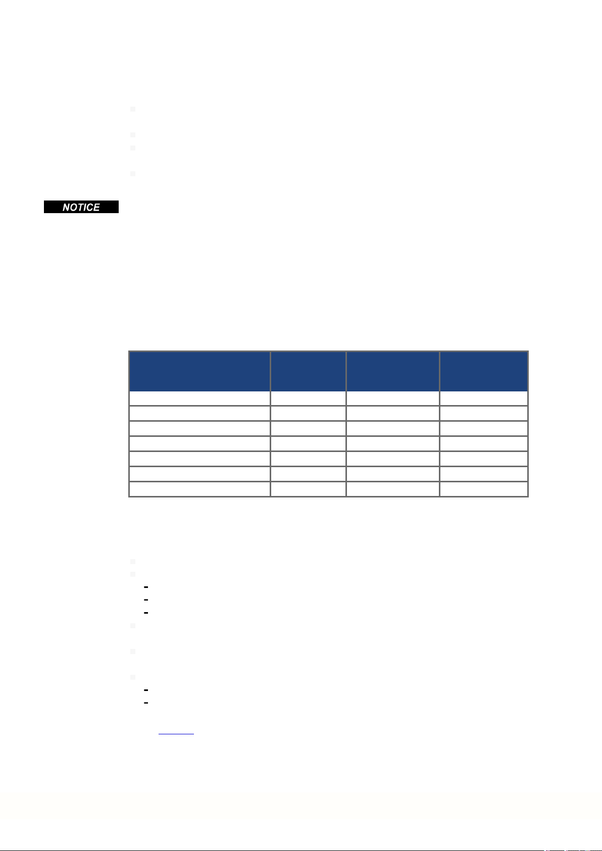
2.3 Symbols Used
Warning Symbols
Symbol Indication
DANGER
Indicates a hazardous situation which, if not avoided, will result
in death or serious injury.
AKD Installation | 2 General
WARNING
CAUTION
Indicates a hazardous situation which, if not avoided, could result in death or serious injury.
Indicates a hazardous situation which, if not avoided, could result in minor or moderate injury.
Indicates situations which, if not avoided, could result in property damage.
This symbol indicates important notes.
Warning of a danger (general). The type of danger is specified
by the text next to the symbol.
Warning of danger from electricity and its effects.
Warning of danger from hot surface.
Warning of danger from suspended loads.
Warning of danger from automatic start.
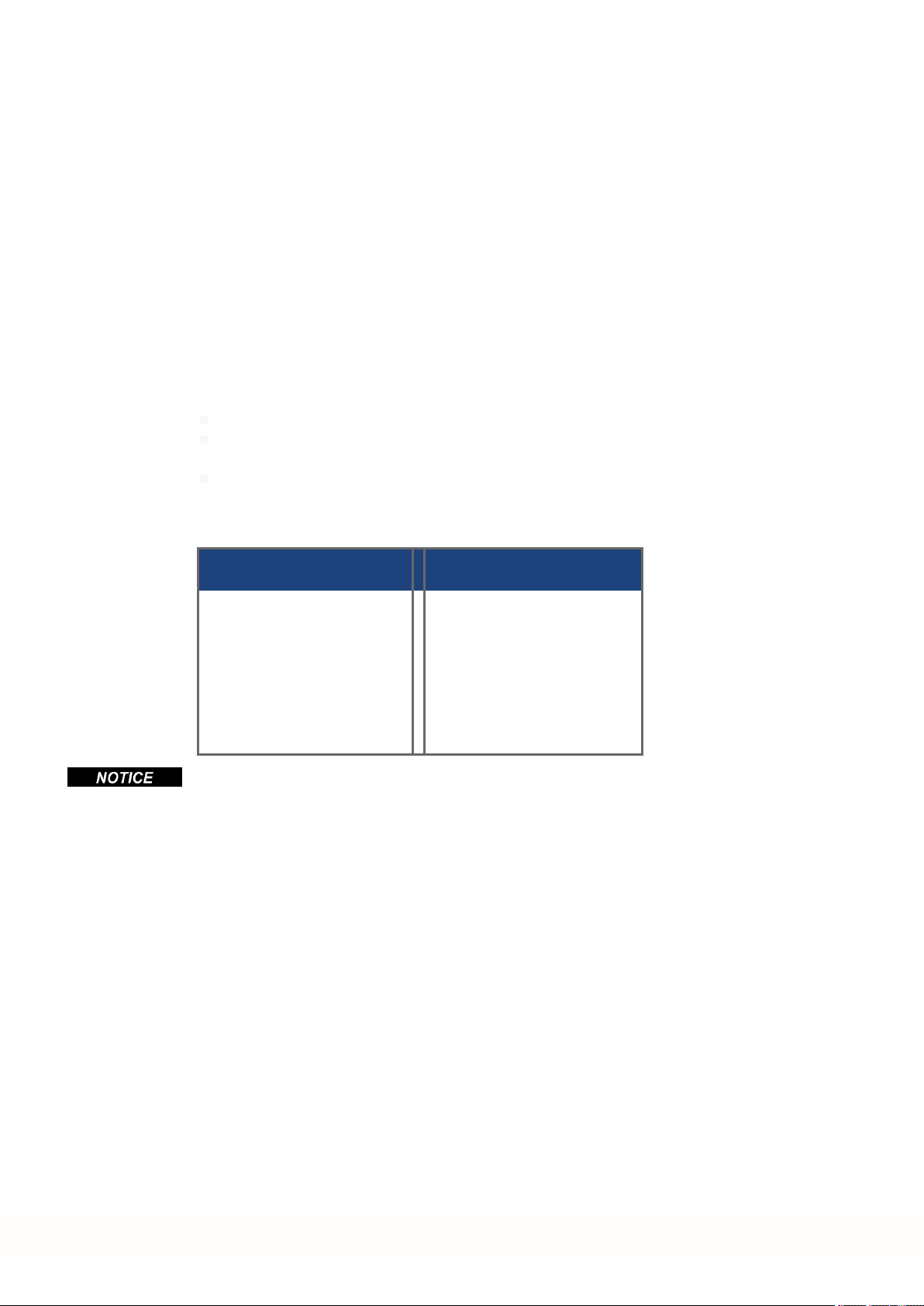
Drawing symbols
Symbol Description Symbol Description
Signal ground Diode
Chassis ground Relay
Protective earth Relay switch off delayed
Resistor Normally open contact
Fuse Normally closed contact
Kollmorgen | kdn.kollmorgen.com | October 2017 11
AKD Installation | 2 General
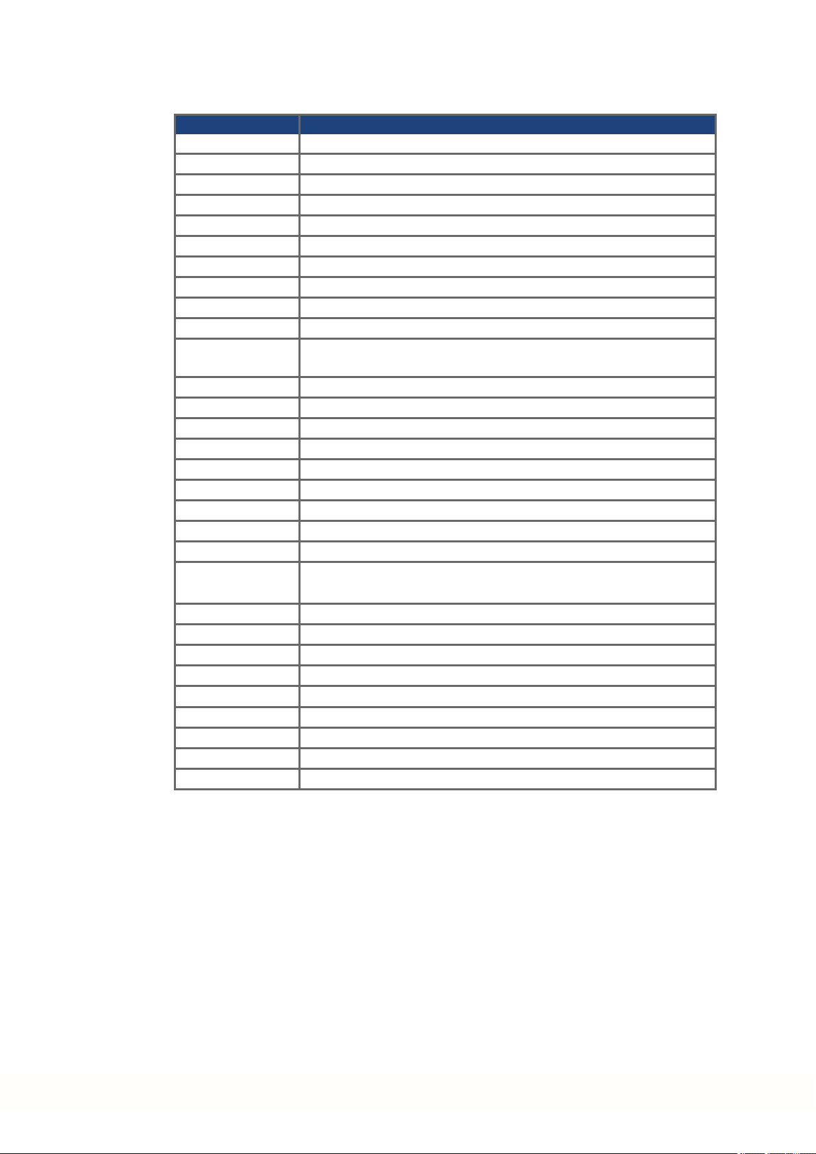
2.4 Abbreviations Used
Abbreviation Meaning
(➜ # 53) "see page 53" in this document
AGND Analog ground
CE Communité Européenne
COM Serial interface for a personal computer
DCOMx Communication line for digital inputs (with x=7 or 8)
Disk Magnetic storage(diskette, hard disk)
EEPROM Electrically erasable programmable memory
EMC Electromagnetic compatibility
F-SMA Fiber optic cable connector according to IEC 60874-2
KAS KollmorgenAutomation Suite
KAS IDE Setup software (KollmorgenAutomation Suite IntegratedDevel-
LED Light-emitting diode
LSB Low significant byte (orbit)
MSB Main significant byte (or bit)
NI Zero pulse
PC Personal computer
PE Protective earth
PLC Programmable logic control
PWM Pulse-width modulation
RAM Random access memory (volatile memory)
R
Brake/RB
opment Environment) used for AKD PDMM drives
Regenresistor (also called a brake resistor)
RBext External regen resistor
RBint Internal regenresistor
RCD Residual current device
RES Resolver
ROD Incremental encoder (A quad B)
S1 Continuous operation
STO Safe torque off
VAC Volts, alternating current
VDC Volts, direct current
12 Kollmorgen | kdn.kollmorgen.com | October 2017

2.5 Referred Standards
Standard Content
ISO 4762 Hexagon socket headcap screws
ISO 11898 Road vehicles — Controller area network (CAN)
ISO 12100 Safety of machinery: Basic concepts, general principles for design
ISO 13849 Safety of machinery: Safety-related parts of control systems
IEC 60085 Electrical insulation - Thermal evaluation and designation Maintenance
IEC 60204 Safety of Machinery: Electrical equipment of machinery
IEC 60364 Low-voltage electrical installations
IEC 60439 Low-Voltage Switchgear and Controlgear Assemblies
IEC 60529 International protection rating (IP code)
IEC 60664 Insulation coordination for equipment within low-voltage systems
IEC 60721 Classification of environmental conditions
IEC 61000 Electromagnetic compatibility (EMC)
IEC 61131 Programmable controllers
IEC 61491 Electrical equipment of industrial machines – Serial data link for real-time com-
IEC 61508 Functional safety of electrical/electronic/programmable electronic safety-
IEC 61800 Adjustablespeed electrical power drive systems
IEC 62061 Functional safety of electrical/electronic/programmable electronic safety-
IEC 82079 Preparation of instructions for use - Structuring, content and presentation
UL 840 UL Standard for Safety for Insulation CoordinationIncluding Clearances and
UL 508C UL Standard forSafety Power ConversionEquipment
AKD Installation | 2 General
munications between controls anddrives.
related systems
related systems
Creepage Distances for Electrical Equipment
IEC - International Electrotechnical Commission
ISO - International Organization forStandardization
UL - Underwriters Laboratories
Kollmorgen | kdn.kollmorgen.com | October 2017 13

AKD Installation | 3 Safety
3 Safety
3.1 You should pay attention to this 15
3.2 Use as Directed 17
3.3 Prohibited Use 18
3.4 Warning notes placed on the product 18
14 Kollmorgen | kdn.kollmorgen.com | October 2017

3.1 You should pay attention to this
This section helps you to recognize and avoid dangers to people and objects.
Specialist staff required!
Only properly qualified personnel are permitted to perform such tasks as transport,
assembly, setup and maintenance. Qualified specialist staff are persons who are familiar
with the transport, installation, assembly, commissioningand operation of drives andwho
bring theirrelevant minimum qualifications to bear ontheir duties:
Transport: only by personnel with knowledgeof handlingelectrostatically sensitive components.
Unpacking: only by electrically qualified personnel.
Installation: only by electrically qualified personnel.
Basic tests / Setup: only by qualified personnel with knowledge of electrical engineering
anddrive technology
The qualifiedpersonnel must know and observe ISO 12100 / IEC 60364 / IEC 60664 and
national accident prevention regulations.
Read the documentation!
Read the availabledocumentation before installation and commissioning. Improper handling
of the drive can cause harm to peopleor damage to property. The operator of systems using
the AKD must require that all personnel who work with the drive read and understand the
manual beforeusing the drive.
AKD Installation | 3 Safety
Check Hardware Revision!
Check the HardwareRevision Number of the product (see product label). This numberis the
link between your product and the manual, it must match the Hardware Revision Numberon
the cover page of the manual.
Pay attention to the technical data!
Adhere to the technical data and the specifications on connection conditions (rating plate and
documentation). If permissible voltagevalues or current values areexceeded, the drives can
be damaged. Unsuitable motor or wrong wiring will damage the system components. Check
the combination of drive and motor. Compare the rated voltage and current of the units.
Perform a risk assessment!
The manufacturer of the machine must generate a risk assessment for the machine, and take
appropriate measures to ensure that unforeseen movements cannot cause injury or damage
to any person or property. Additional requirements on specialist staff may also result from the
risk assessment.
Automatic Restart!
The drive might restart automatically after power on, voltagedip or interruption of the supply
voltage, depending on the parameter setting. Risk of death or serious injury for humans working in the machine.
If the parameter DRV.ENDEFAULT is set to 1, then place a warning sign to the machine
(Warning: Automatic Restart at Power On) and ensure, that power on is not possible, while
humans are in a dangerous zone of the machine. In case of using an undervoltage protection
device, you must observe EN 60204-1:2006 chapter 7.5 .
Kollmorgen | kdn.kollmorgen.com | October 2017 15

AKD Installation | 3 Safety
Observe electrostatically sensitive components!
The drives contain electrostatically sensitive components which may be damaged by incorrect handling. Electrostatically discharge your body before touching the drive. Avoid contact
with highly insulating materials (artificial fabrics, plastic film etc.). Place the drive on a conductive surface.
Hot surface!
Drives may have hot surfaces during operation. The heat sink can reach temperatures above
80°C. Risk of minor burns! Measure the temperature, and wait until the heat sink has cooled
down below 40 °C before touching it.
Earthing!
It is vital that you ensure that the drive is safely earthed to the PE (protective earth)busbar in
the switch cabinet. Risk of electric shock. Without low-resistance earthing no personal protection can be guaranteed.
Leakage Current!
Since the leakage current to PE is more than 3.5 mA, in compliance with IEC61800-5-1 the
PE connection must eitherbe doubled or a connecting cable with a cross-section >10 mm²
must be used. Deviating measures accordingto regional standards might be possible.
High voltages!
The equipment produces high electric voltages up to 900V. Risk of electric shock. Do not
open or touch the equipment during operation. Keep all covers andcabinet doors closed.
Duringoperation, drives may have uncovered live sections, according to theirlevel of enclosureprotection.
Lethal danger exists at live parts of the device. Built-in protection measures such as insulation orshielding may not be removed. Work on the electrical installationmay only be performed by trained and qualified personnel, in compliance with the regulations for safety at
work, and only with switched off mains supply, and secured against restart.
Never undo any electrical connections to the drive while it is live. There is a danger of electrical arcing with damage to contacts and personal injury. Wait at least 7 minutes after disconnecting the drive from the main supply power before touching potentially live sections of
the equipment (such as contacts) or removing any connections.
Always measure the voltage in the DC bus link and wait until the voltage is below 50 V
before handling components.
Functional Safety!
The STO safety implementation on the AKD is certified. The assessment of the safety functions according to EN13849 or EN 62061 must finally be done by the user.
Reinforced Insulation!
Thermal sensors, motor holdingbrakes and feedback systems built into the connected motor
must have reinforcedinsulation (according to IEC61800-5-1)against system components
with power voltage, accordingto the required applicationtest voltage. All Kollmorgen components meet these requirements.
Never modify the drive!
It is not allowed to modify the drive without permission by the manufacturer. Opening the
housing causes loss of warranty.
16 Kollmorgen | kdn.kollmorgen.com | October 2017
3.2 Use as Directed
The AKD drives are exclusively intended for driving suitablesynchronous servomotors with
closed-loopcontrol of torque, speed, and/or position.
AKDs are components that are built into electrical plants or machines and canonly be operated as integral components of these plants or machines. The manufacturer of the machine
used with a drive must generate a risk assessment for the machine. When the drives are built
into machines or plant, the drive must not be used until it has been established that the
machine or plant fulfills the requirements of the regional directives.
Cabinet and wiring
Drives must only be operated in a closed control cabinet suitable for the ambient conditions
(➜ # 32). Ventilation or cooling may be necessary to keep thetemperature within the cabinet
below 40 °C.
Use only copper conductors for wiring. The conductor cross-sections can be derived from the
standard IEC 60204 (alternatively for AWG cross-sections: NEC Table 310-16, 75 °C
column).
Power supply
The drives can be supplied by 1 or 3 phase industrial supply networks.
Drives in the AKD series can be supplied as follows:
AKD Installation | 3 Safety
AKD-xzzz06: 1 or 3 phase industrial supply networks
(not more than 200 kA symmetrical rated current at 120 V and 240 V).
AKD-xzzz07: 3 phase industrial supply networks
(not more than 200 kA symmetrical rated current at 240 V, 400 V and 480 V).
Connection to other voltage types of supply networks is possible with an additional isolating
transformer(➜ # 103).
AKD-x04807: In case of mains voltage asymmetry >3% a mains choke 3L0,24-50-2must be
used.
Periodic overvoltages between phases (L1, L2, L3) andthe housing of the drive must not
exceed 1000V peak. In accordance with IEC 61800, voltage spikes (< 50 µs) between
phases must not exceed 1000 V. Voltage spikes (<50 µs) between a phase andthe housing
must not exceed 2000 V.
EMC filter measures for AKD-xzzz06 must be implementedby the user.
For the cases of group installations and of DC powered drives
AKD has not been evaluatedby Kollmorgen, UL, or TÜV for group installations nor are ratings defined for DC input voltage.
Group installations must be reviewed and evaluated by the user for branch circuit protection*,
wire size, wire voltage rating, fuse protection, system dielectric requirements, overvoltage
andinput** current rating.
In case of DC supplied drives the built-in EMC filter will not work. The useris responsible to
keep the conducted emissions and the immunity of the drive within the required noise levels.
* Special care must be taken in branch circuit design with mixed rating drives to avoid the
smaller drives becoming the effective ‘fuse’ rather than the circuit protective fuse.
** The power supply system design must ensure inrush current protection by limiting input
current duringpower up. DC supply polarity must be properly wired. Improper polarity of DC
powerwill damage the drive and void warranty.
Kollmorgen | kdn.kollmorgen.com | October 2017 17
AKD Installation | 3 Safety
Motor voltage rating
The rated voltage of the motors must be at least as high as the DC bus link voltage divided by
√2 produced by the drive (U
Safe torque off
Review the section "Use as Directed" in the STO chapter(➜ # 57) before using this safety
function (according to ISO 13849 category 3).
3.3 Prohibited Use
Otheruse thanthat described in chapter “Use as directed” is not intended and can lead to personnel injuries and equipment damage. The drive may not be usedwith a machine that does
not comply with appropriate national directives or standards. The use of the drive in the following environments is also prohibited:
potentially explosive areas
environments with corrosive and/or electrically conductive acids, alkaline solutions, oils,
vapors, dusts
ships or offshoreapplications
nMotor
>=UDC/√2).
3.4 Warning notes placed on the product
AKD-x002407 AKD-x00306 ... 02406,
Wait 7 minutes
after removing power
before servicing.
If these signs are damaged, they must be replaced immediately.
00307 ... 01206, 04807
Wait 5 minutes
after removing power
before servicing.
18 Kollmorgen | kdn.kollmorgen.com | October 2017

AKD Installation | 4 Handling
4 Handling
4.1 Transport 20
4.2 Packaging 20
4.3 Storage 20
4.4 Decommissioning 21
4.5 Maintenance and cleaning 21
4.6 Disassemble 21
4.7 System Repair 22
4.8 Disposal 22
Kollmorgen | kdn.kollmorgen.com | October 2017 19
AKD Installation | 4 Handling
4.1 Transport
Transport the AKD in accordance with IEC 61800-2as follows:
Transport only by qualified personnel in the manufacturer’s original recyclable packaging.
Avoid shocks while transporting.
Store at or below maximum stacking height, details see "Storage" (➜ # 20)
Transport only within specified temperature ranges: -25 to +70 °C, max. rate of change
20K/hour, class 2K3.
Transport only within specified humidity: max. 95% relative humidity, no condensation,
class 2K3.
The drives contain electrostatically sensitive components that can bedamaged by incorrect
handling. Electrostatically discharge yourself before touching the drive. Avoid contact with
highly insulating materials, such as artificial fabrics and plastic films. Place the drive on a
conductive surface.
If the packaging is damaged, check the unit for visible damage. Inform the shipper and the
manufacturer of any damage to the package or product.
4.2 Packaging
The AKD packagingconsists of recyclable cardboardwith inserts and a label on the outside
of the box.
4.3 Storage
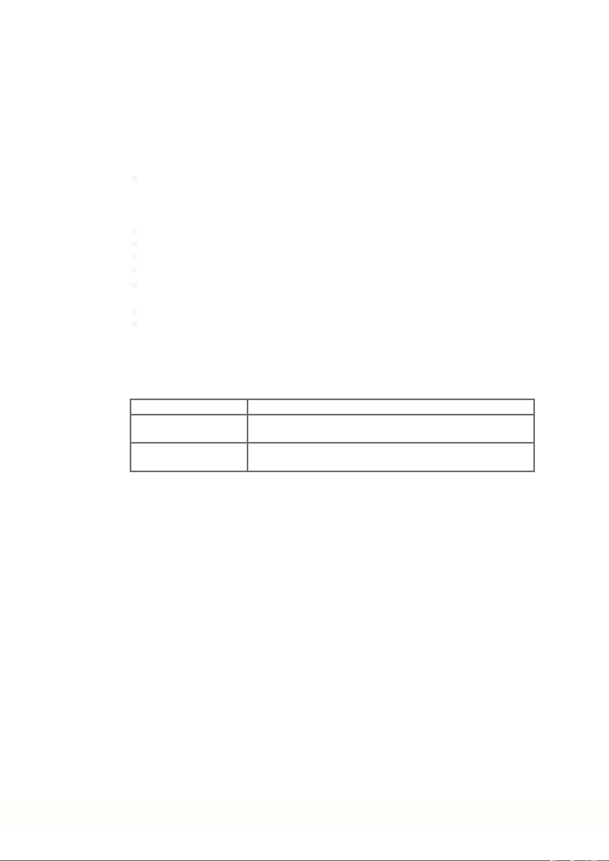
Model Package
Dimensions
(mm) HxWxL
up to AKD-x00606 113 x 250 x 222 1.7 1.9
AKD-x01206 158x 394 x 292 3.4 3.6
AKD-x02406 158x 394 x 292 5 5.2
AKD-x00307 and AKD-x00607 158x 394 x 292 4.3 4.5
AKD-x01207 158x 394 x 292 4.3 4.5
AKD-x02407 158x 394 x 292 6.7 6.9
AKD-x04807 390x 600 x 400 15.3 15.5
Store the AKD in accordance with IEC 61800-2 as follows:
Store only in the manufacturer’s original recyclable packaging.
Store at or below maximum stacking height :
AKD-x00306 to 00606 models: 8 cartons,
AKD-x01206, x02406, x00307 to x02407 models: 6 cartons,
AKD-x04807 models: 3 cartons.
Store only within specified temperatureranges: -25 to +55 °C, max.rate of change
20K/hour, class 1K4.
Storage only within specified humidity: 5 to 95% relative humidity, no condensation, class
1K3.
Store in accordance with the followingdurationrequirements:
Less than 1 year: without restriction.
More than 1 year: capacitors must be re-formed beforesetting up and operating the
drive. Re-formingprocedures are described in theKollmorgen Developer Network
(Forming).
Total Weight
AKD-B, -P, -T
(kg)
Total Weight
AKD-M
(kg)
20 Kollmorgen | kdn.kollmorgen.com | October 2017
4.4 Decommissioning
Only professional staff who are qualified in electrical engineeringare allowedto decommission parts of the system.
DANGER: Lethal Voltages!
There is a dangerof serious personal injury or death by electrical shock or electrical arcing.
Switch off the mainswitch of the switchgearcabinet.
Securethe system against restarting.
Block the mainswitch.
Wait at least 7 minutes after disconnecting.
4.5 Maintenance and cleaning
The device does not require maintenance. Opening the device voids the warranty. The inside
of the unit can only be cleaned by the manufacturer.
Do not immerse orspray the device. Avoid that liquidenters the device.
To clean the device exterior:
1. Decommission the device (see chapter 4.4 "Decommissioning").
2. Casing: Clean with isopropanol or similarcleaning solution.
Caution : Highly Flammable! Risk of injury by explosion and fire.
Observe the safety notes given on the cleaning liquid package.
Wait at least 30 minutes after cleaningbefore putting the device back into operation.
3. Protective grill onfan: Clean with a dry brush.
AKD Installation | 4 Handling
4.6 Disassemble
Only professional staff who are qualified in electrical engineeringare allowedto disassemble
parts of the system.
1. Decommission the device (see chapter 4.4 "Decommissioning").
2. Check temperature.
3. Remove the connectors. Disconnect the potential earth connection last.
4. Demount: loosen the fastening screws. Remove the device.
CAUTION: High Temperature! Risk of minorburns. During operation, the heat sink of
the drive may reach temperatures above 80°C (176°F). Before touching the device,
check the temperature andwait until it has cooled below 40°C (104°F).
Kollmorgen | kdn.kollmorgen.com | October 2017 21
AKD Installation | 4 Handling
4.7 System Repair
Only professional staff who are qualified in electrical engineeringare allowedto exchange
parts of the drive system.
CAUTION: Automatic Start! During replacement work a combination of hazards andmul-
tiple episodes may occur.
Work on the electrical installation may only be performed by trained and qualified per-
sonnel, in compliance with the regulations for safety at work, andonly with use of pre-
scribed personal safety equipment.
Exchange of AKD
Only the manufacturer can repair the device. Opening the device voids the warranty.
1. Decommission the device (see chapter 4.4 "Decommissioning").
2. Demount the device (see chapter 4.6 "Disassemble").
3. Send the device to the manufacturer.
4. Install a new device as describedin this manual.
5. Setup the system as described in this manual.
Exchange of other drive system parts
If parts of the drive system (for example cables) must be replaced, proceed as follows:
4.8 Disposal
1. Decommission the device (see chapter 4.4 "Decommissioning").
2. Exchange the parts.
3. Check all connections for correct fastening.
4. Setup the system as described in this manual.
To dispose the unit properly, contact a certified electronic scrap disposal merchant.
In accordance with the WEEE-2002/96/EC-Guidelines and similar, the manufacturer accepts
returns of old devices andaccessories for professional disposal. Transport costs are the
responsibility of the sender.
Send thedevices in the original packaging to the manufacturer address:
North America South America
Kollmorgen
201West Rock Road
Radford, VA 24141, USA
Europe Asia
KOLLMORGEN Europe GmbH
Pempelfurtstr. 1
40880 Ratingen, Germany
Kollmorgen
AvenidaTamboré - 1077 Tamboré
Barueri - SP Brasil
CEP:06460-000, Brazil
KOLLMORGEN
Room 202, Building 3, Lane 168,
Lin HongRoad, Changning District
Shanghai, China
22 Kollmorgen | kdn.kollmorgen.com | October 2017

AKD Installation | 5 Approvals
5 Approvals
5.1 Conformance with UL/cUL 24
5.2 Conformance with CE 26
5.3 Safe Torque Off (STO) approval 28
5.4 Conformance with EAC 28
Kollmorgen | kdn.kollmorgen.com | October 2017 23
AKD Installation | 5 Approvals
5.1 Conformance with UL/cUL
This drive is listed underUL (Underwriters Laboratories Inc.) file number E141084 Vol.3 Sec.5.
USL, CNL – Power conversionequipment (NMMS, NMMS7) – Models AKD followed by B, P, T or M, followed
by 003, 006, 012, 024 and 048, followed by 06 or 07, followed by additional suffixes.
USL (United States Standards - Listed): Indicates Investigated to United States Standardfor Power Conversion Equipment, UL 508C.
CNL (Canadian National Standards - Listed): Indicates investigationto Canadian Standard for Industrial Control Equipment, CAN/CSA - C22.2, No. 14-13.
5.1.1 UL Markings / Marquages UL
English Français
Identification of the terminals on the controller
arecoded so they may be identified in the instructions. The instructions shall identify power connections for power supply, load, control, and
ground.
Integral solid state short circuit protection does
not provide branch circuit protection. Branch circuit protection must be provided in accordance
with the National Electrical Code andany additional local codes.
This product is suitable for use on a circuit capableof delivering not more than 200,000 rms symmetrical amperes, 240 V (AKD-xzzz06) / 480 V
(AKD-xzzz07)volts maximum, when protected
by fuses.
These drives provide solid state motor overload
protection at 125% of the rated FLA Current.
These devices are intended to be used in a pollution degree 2 environment.
Maximum surrounding airtemperature of 40°C. La température de l'air ambiant doit être de 40°C max-
Use minimum 75°C copper wire. Utilisez un fil en cuivre 75 °C minimum.
These devices do not provide overtemperature
sensing.
Use fuses only. Utilisez uniquement des fusibles.
CAUTION Risk of Electrical Shock! Capa-
citors can have dangerous voltages present up to
seven minutes after switching off the supply
power. For increased safety, measurethe
voltage in the DC bus link andwait until the
voltage is below 50 V.
Les bornes de l'unité de contrôle sont codées pour faciliter leuridentification dans les instructions. Les instructions doivent identifier les raccordements
d'alimentation, de charge, de commande et de terre.
Une protection de court-circuit à semi-conducteur intégrale ne fournit pas de protection de la dérivation. Il convient de garantir uneprotection de la dérivation
conforme au NEC (National Electrical Code) et aux
réglementations locales en vigueur, ou aux directives
équivalentes applicables.
Ce produit est conçu pourune utilisation sur un circuit
capable defournir 200 000 ampères symétriques (rms)
maximum pour 240 V (AKD-xzzz06) / 480V (AKDxzzz07) maximum, s'il dispose de fusibles ou deprotections équivalentes.
Ces variateurs offrent une protection contre les surcharges de moteur à semi-conducteur à 125 % du courant FLA nominal.
Ces appareils sont prévus pour une utilisation dans un
environnement de pollution de niveau2.
imum ou une valeur équivalente.
Ces variateurs n'offrent pas de capteurs de température excessive.
ATTENTION: Risque de choc électrique! Des tensions dangereuses peuvent persister dans les condensateurs jusqu'à sept minutes après la mise hors
tension. Pour plus de sécurité, mesurez la tension
dans la liaison de bus CC et attendez qu'elle soit
inférieure à 50 V.
24 Kollmorgen | kdn.kollmorgen.com | October 2017
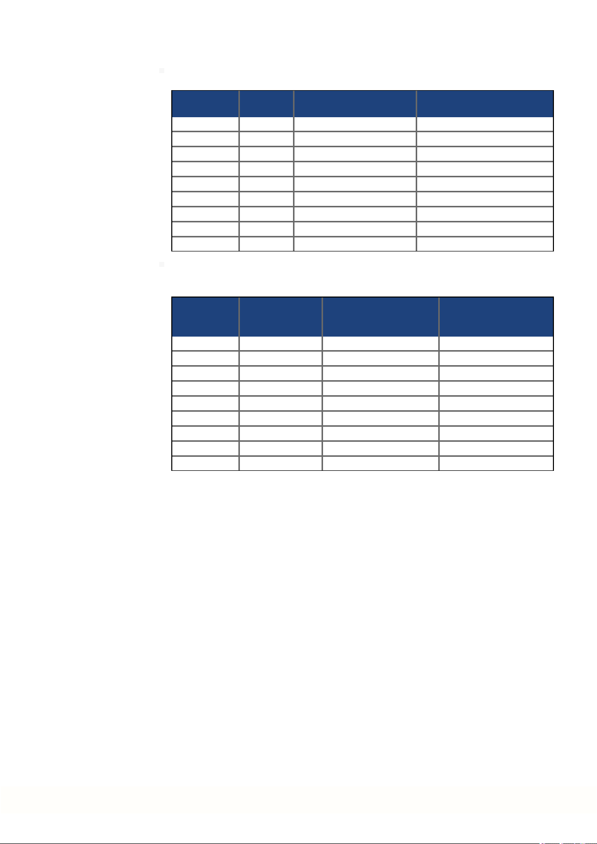
AKD Installation | 5 Approvals
The following fuse types are recommended /
Les types de fusibles suivants sont recommandés :
Model
Modèle
Class/
Classe
Rating/
Niveau
Max. Fuse Rating/
Niveau maximum
AKD-x00306 J 600VAC, 200 kA 10 A
AKD-x00606 J 600VAC, 200 kA 15 A
AKD-x01206 J 600VAC, 200 kA 15 A
AKD-x02406 J 600VAC, 200 kA 30 A
AKD-x00307 J 600VAC, 200 kA 6 A
AKD-x00607 J 600VAC, 200 kA 10 A
AKD-x01207 J 600VAC, 200 kA 15 A
AKD-x02407 J 600VAC, 200 kA 30 A
AKD-x04807 J 600VAC, 200 kA 60 A
The following table illustrates the torquerequirements for the field wiring connectors /
Le tableausuivant indique les spécifications de couple pour les connecteurs de câblage
sur site:
Model/
Modèle
Mains Con-
nector/ Con-
necteur secteur
Motor Phase Connector/
Connecteur de phase
moteur
24 VDC Input Con-
nector/ Connecteur
d'entrée 24Vcc
AKD-x00306 5-7 in-lbs 5-7in-lbs 4 in-lbs
AKD-x00606 5-7 in-lbs 5-7in-lbs 4 in-lbs
AKD-x01206 5-7 in-lbs 7 in-lbs 4in-lbs
AKD-x02406 7 in-lbs 7 in-lbs 4in-lbs
AKD-x00307 7 in-lbs 7 in-lbs 4in-lbs
AKD-x00607 7 in-lbs 7 in-lbs 4in-lbs
AKD-x01207 7 in-lbs 7 in-lbs 4in-lbs
AKD-x02407 7 in-lbs 7 in-lbs 4in-lbs
AKD-x04807 13 in-lbs 13 in-lbs 4in-lbs
Kollmorgen | kdn.kollmorgen.com | October 2017 25
AKD Installation | 5 Approvals
5.2 Conformance with CE
Conformance with the EC EMC Directive 2014/30/EC and the Low Voltage Directive
2014/35/EC is mandatory for the supply of drives within the European Community.
CE Declarations of Conformity can be foundon the Kollmorgenwebsite.
The drives have been tested by an authorized testing laboratory in a defined configuration,
using the system components that are described in this documentation. Any divergence from
the configuration andinstallationdescribed in this documentationmeans that the user will be
responsiblefor carrying out new measurements to ensure conformance with regulatory
requirements.
Kollmorgen declares the conformity of the product series AKD with the following directives:
EC Directive 2006/42/EC, Machinery Directive
Used harmonized standard EN61800-5-2 (2007)
EC Directive 2014/35/EC, Low Voltage Directive
Used harmonized standard EN61800-5-1 (2007)
EC Directive 2014/30/EC, EMC Directive
Used harmonized standard EN 61800-3 (2004)
These devices can cause high-frequency interferences in non industrial environments and
may requiremeasures for interference suppression (such as additional external EMC filters).
AKD-xzzz06
AKD-xzzz06 drives do not have integrated EMC filters.
With external EMC filters for noise emission the AKD-xzzz06 meet the noise immunity
requirements of the secondenvironmental category (industrial environment) to a product of
the category C2 (motor cable < 10 m).
With a motor cable length of 10 m or longer and external EMC filters, the AKD-xzzz06 meet
the requirement of category C3.
AKD-xzzz07
AKD-xzzz07 drives have integrated EMC filters.
The AKD-xzzz07 meet the noise immunity requirements to the 2nd environmental category
(industrial environment). For noise emission the AKD-xzzz07 meet the requirement to a
product of the Category C2 (motor cable < 10 m).
With a motor cable length of 10 m or longer, the AKD-xzzz07 meet the requirement to the Category C3.
AKD-x04807: In case of mains voltage asymmetry >3% a mains choke 3L0,24-50-2must be
used.
26 Kollmorgen | kdn.kollmorgen.com | October 2017
5.2.1 European Directives and Standards for the Machine Builder
Drives are components that are intendedto be incorporated into electrical plant and
machines for industrial use. Whenthe drives are built into machines or plant, the drive must
not be used until it has been established that the machine or equipment fulfills the requirements of the
EC Machinery Directive (2006/42/EC)
EC EMC Directive (2014/30/EC)
EC Low VoltageDirective (2014/35/EC)
Standards to be applied for conformance with the EC Machinery Directive (2006/42/EC)
IEC 60204-1 (Safety and Electrical Equipment in Machines)
ISO 12100 (Safety of Machines)
The manufacturer of the machine must generate a risk assessment for the machine, and
must implement appropriate measures to ensurethat unforeseen movements cannot cause
injury or damage to any personor property.
Standards to be applied for conformance with the EC Low Voltage Directive(2014/35/EC)
IEC 60204-1 (Safety and Electrical Equipment in Machines)
IEC 60439-1 (Low-voltage switchgear and controlgearassemblies)
AKD Installation | 5 Approvals
Standards to be applied for conformance with the EC EMC Directive (2014/30/EC)
IEC 61000-6-1/2 (Interference Immunity in Residential & Industrial Areas)
IEC 61000-6-3/4 (Interference Generation in Residential & Industrial Areas)
The manufacturer of the machine/plant is responsible for ensuring that it meets the limits
required by the EMC regulations. Advice on the correct installation for EMC (such as shielding, grounding, treatment of connectors and cable layout) is shown in this manual.
The machine/plant manufacturer must check whether other standards or EC Directives
must be applied to the machine/plant.
Kollmorgen only guarantees the conformance of the servosystem with the standards cited in
this chapter if the components (motor, cables, chokes etc.) are those supplied by Kollmorgen.
5.2.2 Conformance with RoHS
Directive 2011/65/EC of the European Union on the restriction of the use of certain hazardous substances in electrical and electronic equipment (RoHS) became operative as from
the 3rd of January, 2013. Following substances namely are involved
Lead (Pb), Cadmium (Cd), Hexavalent chromium (CrVI), Polybrominated biphenyls (PBB),
Polybrominated diphenyl ethers (PBDE), Mercury (Hg)
The AKD is manufacturedin conformance with RoHS.
5.2.3 Conformance with REACH
EU Regulation no. 1907/2006 deals with the registration, evaluation, authorization and restriction of chemical substances 1 (abbreviated to "REACH").
AKD does not contain any substances (CMR substances, PBTsubstances, vPvB substances and similar hazardous substances stipulated in individual cases based onscientific
criteria) above 0.1 mass percent per product that are included onthe candidate list.
Kollmorgen | kdn.kollmorgen.com | October 2017 27
AKD Installation | 5 Approvals
5.3 Safe Torque Off (STO) approval
An additional digital input (STO, Safe Torque Off) releases the power output stage of the drive
as long as a 24V signal is applied to this input. If the STO input goes open-circuit, then power
will no longer be suppliedto the motor, and the drive will lose all torque and coast to a stop.
The STO safety implementation on the AKD is certified. The safety circuit implementation for
realizing the safety function "Safe Torque Off" in the drive is suited for SIL2 according to IEC
62061 and PLd, Cat.3 according to ISO 13849-1.
With AKD-x04807 drives SIL3/PLe is possible, if both STO-Enable inputs are used with the
corresponding STO-Status signals.
Safety certificates can be found on the Kollmorgen website.
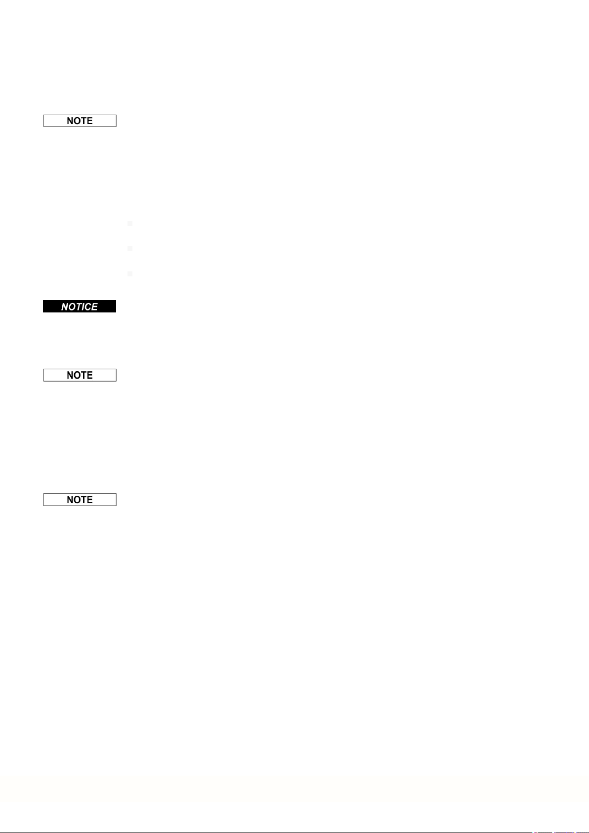
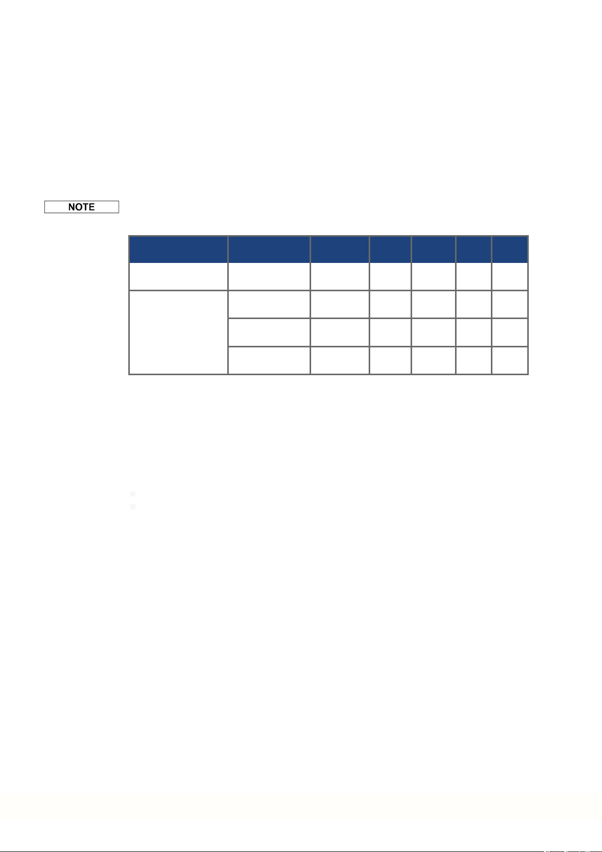
The subsystems (AKD) are totally described for safety technics with the characteristic data :
Device Operation
AKD-x003...024 single
AKD-x048 single
5.4 Conformance with EAC
EAC is the abbreviation for EurasianConformity. The mark is used in the states of the Eurasian Customs Union (Russia, Belarus, Kazakhstan) similar to the European CE mark.
Kollmorgen declares, that the AKD has passed all required conformity procedures in a memberstate of the Eurasian Customs Union, andthat the AKD meets all technical requirements
requested in the member states of the Eurasian Customs Union:
Low voltage (TP TC 020/2011)
Electromagnetic Compatibility (TP TC 004/2011)
Contact: Intelisys LLC. , Bakuninskaya Str. d 14, Building10, RU-105005 Moskau
Mode
channel
channel
dual
channel
dual channel with
periodical testing
ISO
13849-1
PL d, CAT 3 SIL 2 1.50E-07 20 100
PL d, CAT 2 SIL 2 1.88E-07 20 89
PL d, CAT 3 SIL 2 5.64E-09 20 87
PL e, CAT 4 SIL 3 5.64E-09 20 87
IEC
62061
PFH
[1/h]
T
M
[Years]
SFF
[%]
28 Kollmorgen | kdn.kollmorgen.com | October 2017

AKD Installation | 6 Package
6 Package
6.1 Package Supplied 30
6.2 Nameplate 30
6.3 Part Number Scheme 31
Kollmorgen | kdn.kollmorgen.com | October 2017 29

AKD Installation | 6 Package
6.1 Package Supplied
When a drive from the AKD series is ordered, the following items are includedin the drive
package:
AKD
Printedcopy of AKD Safety Guide
DVD containing the AKD Installation Manual, all fieldbus manuals, the setup software
WorkBench, and more product documentation in digital format.
Mating connectors (if required forthe drive variant): X1, X2, X3, X4, X7, X8, X14, X15,
X16, X21, X22, X23, X24, X35, X36
Grounding plate, with AKD voltagetype 07, with voltage type 06 for EU only
The mating SubD andRJ45 connectors are not included in the package.
Accessories Sold Separately
Accessories must be orderedseparately if required; referto your regional accessories
manual:
EMC filters for 24 V and mains supply voltage, categories C2 or C3
External regen resistor
Motor cable. Assembled motor cables are available for all regions.
Feedback cable. Assembledfeedback cables areavailable for all regions.
Motor choke, for motor cables longer than 25 m
CAN termination connector (with CAN drives only)
Service cable to the network
Power cable, control cables, andfieldbus cables (as cutoff lengths)
6.2 Nameplate
The nameplate depicted below is attachedto the side of the drive, sample data entries are for
a 12A type. Picture similar to the nameplate on thedevice.
30 Kollmorgen | kdn.kollmorgen.com | October 2017
 Loading...