

Kollmorgen AKD2G-S Series, AKD2G Series, AKD2G-S-7V03, AKD2G-S-7V12, AKD2G-S-6V03 Installation Manual
...
AKD®2G-Sxx with Functional Safety Option 1
STO - SIL2
Installation Manual
Manual Edition: -, Beta, December 2018
Safety Edition: S101, December2018
Valid for AKD®2G-S HardwareRevision A
Part Number907-200003-00
Original Document
Forsafe and proper use, follow
these instructions.
Keepthem for future reference.
Beta Drives: Approvals (CE, Functional Safety, UL) arepending.

Record of Document Revisions
Revision Remarks
...
Table with lifecycle informationof this document (➜ # 145)
Beta, 12/2018 Beta edition
Hardware Revision (HR)
AKD2G Firmware Workbench KAS IDE Remarks
A from 02-00-00-000 from 2.00.0.0000 from 3.01 Beta revision
Trademarks
AKD is a registered trademark of Kollmorgen Corporation
EnDat is a registeredtrademark of Dr. Johannes Heidenhain GmbH
EtherCAT is a registered trademark and patented technology, licensedby Beckhoff Automation GmbH
Ethernet/IP is a registered trademark of ODVA, Inc.
Ethernet/IP Communication Stack: copyright (c) 2009, Rockwell Automation
HIPERFACE is a registeredtrademark of Max StegmannGmbH
Windows is a registeredtrademark of Microsoft Corporation
Technical changes which improve the performance of the device may be made without prior notice!
This document is the intellectual property of Kollmorgen. All rights reserved. No part of this work may be reproduced
in any form (by photocopying, microfilm or any other method) or stored, processed, copied or distributed by electronic
means without the written permission of Kollmorgen.
2 Kollmorgen | kdn.kollmorgen.com | Beta, December 2018

AKD2G-S Installation, Safety 1 | Tableof Contents
1 Table of Contents
1 Table of Contents 3
2 General 9
2.1 About thisInstallationManual 10
2.2 Using the PDF Format 10
2.3 SymbolsUsed 11
2.4 AbbreviationsUsed 12
2.5 Referred Standards 13
3 Product Safety 14
3.1 You shouldpay attention to this 15
3.2 Shock-hazard Protection 17
3.2.1 Leakage current 17
3.2.2 Residualcurrent protective device (RCD) 17
3.2.3 Isolatingtransformers 17
3.3 Stop / Emergency Stop / EmergencyOff 18
3.3.1 Stop 18
3.3.2 Emergency Stop 19
3.3.3 Emergency Off 19
3.4 Warning note labels 20
3.4.1 Notes placedon the product 20
3.4.2 Adhesive labelin the package 20
3.5 Use asDirected 21
3.6 Prohibited Use 22
4 Product life cycle handling 23
4.1 Transport 24
4.2 Packaging 24
4.3 Storage 24
4.4 Installation, setup and normal operation 25
4.5 Decommissioning 25
4.6 Maintenance and cleaning 25
4.7 Disassembly 25
4.8 SystemRepair 26
4.9 Disposal 26
5 Package 27
5.1 PackageSupplied 28
5.2 Nameplate 28
5.3 Part Number Scheme 29
6 Technical description and data 30
6.1 The AKD2G Familyof Digital Drives 31
6.2 Ambient Conditions,Ventilation, and Mounting Position 33
6.3 MechanicalData 33
6.4 Performance Data 34
6.5 Electrical data 35
6.5.1 Singleaxisvariants (S) 35
6.5.1.1 Mains supply data, 1 phaseAC, type AKD2G-Sxx- (S) 35
6.5.1.2 Mains supply data, 3 phaseAC, type AKD2G-Sxx- (S) 35
6.5.1.3 Auxiliary voltage input data, 24V DC, type AKD2G-Sxx- (S) 35
6.5.1.4 Output data, type AKD2G-Sxx- (S) 36
6.5.2 Dual axisvariants(D: I1=I2) 37
6.5.2.1 Mains supply data, 1 phaseAC, type AKD2G-Sxx- (D) 37
6.5.2.2 Mains supply data, 3 phaseAC, type AKD2G-Sxx- (D) 37
Kollmorgen | kdn.kollmorgen.com | Beta, December 2018 3

AKD2G-S Installation, Safety 1 | Tableof Contents
6.5.2.3 Auxiliary voltage input data, 24V DC, type AKD2G-Sxx- (D) 37
6.5.2.4 Output data, type AKD2G-Sxx- (D) 38
6.6 LCD Displayand Push-buttons (B1, B2) 39
6.7 SD Card Slot 41
6.8 Electrical Motor Braking 42
6.8.1 DynamicBraking 42
6.8.2 Rheostatic energy dissipation 42
6.8.2.1 Functional description 42
6.8.2.2 Technicaldata for AKD2G-Sxx-6V 43
6.8.2.3 Technicaldata for AKD2G-Sxx-7V 44
7 Mechanical Installation 45
7.1 Important Notes 46
7.2 Guideto MechanicalInstallation 46
7.3 Dimensions 47
8 Electrical Installation 48
8.1 Important Notes 49
8.2 Guideto electricalinstallation 50
8.3 Wiring 51
8.3.1 General 51
8.3.2 Mating connectors 51
8.3.3 Cable and Wire Requirements 52
8.3.3.1 Cable material 52
8.3.3.2 Cable crosssectionsand requirements 53
8.3.4 ProtectiveEarth connection 54
8.4 EMI NoiseReduction 55
8.4.1 Recommendations for EMI noisereduction 55
8.4.2 Shielding with external shieldingbusbar 56
8.4.2.1 ShieldingConcept 56
8.4.2.2 ShieldingBusbar 57
8.4.3 Shielding connectionto the drive 58
8.4.3.1 ShieldingConcept 58
8.4.3.2 Grounding plates and shield connection clamps 59
8.4.3.3 Motor connector X1/X2 with shielding connection 59
8.5 Connection Overview 60
8.5.1 Connector PositionAKD2G-Sxx-6V 60
8.5.2 Connector PositionAKD2G-Sxx-7V 61
8.5.3 Wiring overview, single axisdrive 62
8.5.4 Wiring overview, dualaxisdrive 63
8.5.5 Connector pin assignments 64
8.5.5.1 X1 and X2: Motor, Brake, Feedback1 64
8.5.5.2 X3: Mains,regen resistor, DC-Bus 64
8.5.5.3 X10: 24 VDC 65
8.5.5.4 X11, X12: Motion Bus 65
8.5.5.5 X13, X14: CAN bus (optional) 65
8.5.5.6 X20: Service 65
8.5.5.7 X21: I/O, Feedback 4 66
8.5.5.8 X22: I/O extended, EEO2,Feedback5 67
8.5.5.9 X23: Feedback 3, EEO1,I/O 68
8.5.5.10 X41: SFA Feedback converter, EEO3/EEO4(accessory) 69
8.6 Power and Logic Voltage Supply (X3/X10) 70
8.6.1 Mainspower supply(X3) 70
8.6.1.1 Fusing 71
8.6.1.2 Wiring examplesmainspower supply 73
8.6.2 Auxiliary voltage power supply 24 VDC (X10) 75
4 Kollmorgen | kdn.kollmorgen.com | Beta, December 2018

AKD2G-S Installation, Safety 1 | Tableof Contents
8.6.2.1 Fusing 75
8.6.2.2 Wiring example24 VDC supply 75
8.7 DC Bus link (X3) 75
8.8 External Regen resistor (X3) 76
8.8.1 Fusing and Wiring 76
8.9 Motor Power, Brake and Feedback connection 77
8.9.1 Motor connectivity, some examples 77
8.9.2 Motor singlecable connection 78
8.9.2.1 Motor Power, Brake and Feedback connectors X1, X2 78
8.9.2.2 Feedbackconnectors X21, X22, X23 79
8.9.3 Motor dual cableconnection 80
8.9.3.1 Motor power and motor brake connectorsX1, X2 81
8.9.3.2 Feedbackconnectors X1, X2, X41, X21, X22, X23 81
8.9.4 Motor Holding Brake Connection 82
8.9.5 Feedback Connection 84
8.9.5.1 FeedbackConnector X1, X2 85
8.9.5.2 FeedbackConnector X21 86
8.9.5.3 FeedbackConnector X22 87
8.9.5.4 FeedbackConnector X23 88
8.9.5.5 FeedbackConnector X41 (SFA, accessory) 89
8.10 ElectronicGearing, EEO,Master-Slave 90
8.10.1 ElectronicGearing 90
8.10.2 Emulated Encoder Output (EEO) 91
8.10.3 Master-Slavecontrol 93
8.10.3.1 Master-Slaveusing X22 93
8.10.3.2 Master-Slaveusing optionalX23 or X41 93
8.11 Motion BusInterface (X11/X12) 94
8.12 CAN-BusInterface (X13/X14) 95
8.12.1 CAN-Bus Topology 95
8.12.2 CAN-Bus Wiring 96
8.12.3 Baud rate for CAN-Bus 97
8.12.4 Node Address for CAN-Bus 97
8.12.5 CAN-Bus Termination 97
8.13 ServiceInterface (X20) 98
8.13.1 Possible NetworkConfigurations 98
8.14 I/O Connection (X21/X22/X23) 99
8.14.1 Pinout 99
8.14.2 Technicaldata 100
8.14.3 Analog Input 101
8.14.4 Analog Output 102
8.14.5 DigitalInputs 103
8.14.5.1 Digital-In 1 and 2 103
8.14.5.2 Digital-In 3 to 12 104
8.14.5.3 Digital-In/Out 1 and 2 105
8.14.5.4 Digital-In/Out 3 to 6 106
8.14.6 DigitalOutputs 107
8.14.6.1 Digital-Out 1 to 6 107
8.14.6.2 Digital-Out 7 and 8 108
8.14.6.3 Digital-In/Out 1 and 2 109
8.14.6.4 Digital-In/Out 3 to 6 109
8.14.6.5 Digital-Out 9, Relaycontacts 110
9 Setup 111
9.1 Important Notes 112
9.2 Guideto drive setup 113
Kollmorgen | kdn.kollmorgen.com | Beta, December 2018 5

AKD2G-S Installation, Safety 1 | Tableof Contents
9.2.1 InitialDrive Test Procedure 113
9.2.1.1 Unpacking, mounting, and wiring the AKD2G 113
9.2.1.2 Minimum wiring for drive testwithout load, example 113
9.2.1.3 Confirm connections (example: directlyto PC) 114
9.2.1.4 System integration 114
9.2.1.5 Installand start WorkBench 115
9.2.1.6 Setup the axisin WorkBench 115
9.2.1.7 Enable the axis(Hardware) 115
9.2.1.8 Move the motor axis 115
9.2.1.9 Tune the axis 115
9.2.2 Setup software WorkBench 116
9.2.2.1 Use as directed 116
9.2.2.2 Software description 117
9.2.2.3 Hardware requirements 117
9.2.2.4 Operating systems 117
9.2.2.5 Installation under Windows 7/8/10 118
9.3 Switch-On and Switch-OffBehavior 119
9.3.1 Switch-on behavior instandard operation 120
9.3.2 Switch-off behavior 120
9.4 Fault and Warning Messages 121
9.4.1 Fault and warning messages AKD2G 121
9.5 Troubleshootingthe AKD2G 122
10 Functional Safety 123
10.1 General notes 124
10.2 Use asdirected 124
10.3 Prohibited use 125
10.4 Abbreviationsused for functionalsafety 125
10.5 Enclosure, wiring 126
10.6 Functional SafetyOption 1 (I/O, SIL2 PLd) 127
10.6.1 TechnicalData 127
10.6.2 Safety Properties Overview 128
10.6.3 STO (Safe Torque Off) 129
10.6.3.1 Description 129
10.6.3.1.1 Important Notes 129
10.6.3.1.2 Precondition before activation 129
10.6.3.1.3 Activation 129
10.6.3.1.4 Restart 130
10.6.3.1.5 Timing 131
10.6.3.2 Safety Diagnosticviewin WorkBench 131
10.6.3.3 Fault Reaction / Failure Messages 132
10.6.4 Verification,Commissioning 132
10.6.4.1 Verification 132
10.6.4.2 Proof test 132
10.7 Safety Faults,Safety Warnings 133
10.7.1 Drive LCD Display 133
10.7.2 Drive Safety Faults 134
10.7.3 Drive Safety Warnings 134
10.7.4 Troubleshootingsafety functionality 134
10.8 Functional SafetyKeyword Reference Guide 135
10.8.1 AXISx.SAFE.STO Parameters 136
10.8.1.1 AXIS#.SAFE.STO.ACTIVE 136
10.8.1.1.1 Description 136
10.8.1.1.2 Context 136
6 Kollmorgen | kdn.kollmorgen.com | Beta, December 2018

AKD2G-S Installation, Safety 1 | Tableof Contents
10.8.1.1.3 Versions 136
10.8.1.1.4 General Information 136
10.8.1.1.5 Variants Supported 136
10.8.1.2 AXIS#.SAFE.STO.A 137
10.8.1.2.1 Description 137
10.8.1.2.2 Context 137
10.8.1.2.3 Versions 137
10.8.1.2.4 General Information 137
10.8.1.2.5 Variants Supported 137
10.8.1.3 AXIS#.SAFE.STO.B 138
10.8.1.3.1 Description 138
10.8.1.3.2 Context 138
10.8.1.3.3 Versions 138
10.8.1.3.4 General Information 138
10.8.1.3.5 Variants Supported 138
10.8.1.4 AXIS#.SAFE.STO.REPORTFAULT 139
10.8.1.4.1 Description 139
10.8.1.4.2 Context 139
10.8.1.4.3 Versions 139
10.8.1.4.4 General Information 139
10.8.1.4.5 Variants Supported 139
11 Approvals 140
11.1 Conformance with UL/cUL 141
11.2 Conformance with CE 141
11.3 Conformance with RoHS 141
11.4 Conformance with REACH 141
11.5 Functional Safetyapproval 141
11.6 Conformance with EAC 141
12 Index 143
13 Record of document revisions 145
Kollmorgen | kdn.kollmorgen.com | Beta, December 2018 7

AKD2G-S Installation, Safety 1 |
---/ ---
8 Kollmorgen | kdn.kollmorgen.com | Beta, December 2018

AKD2G-S Installation, Safety 1 | 2 General
2 General
2.1 About this Installation Manual 10
2.2 Using the PDF Format 10
2.3 Symbols Used 11
2.4 Abbreviations Used 12
2.5 Referred Standards 13
Kollmorgen | kdn.kollmorgen.com | Beta, December 2018 9
AKD2G-S Installation, Safety 1 | 2 General
2.1 About this Installation Manual
This document, the AKD®2G Installation Manual ("Instructions Manual" accordingto EC
Machinery Directive 2006/42/EC), describes the AKD®2G series of digital drives and
includes informationneeded to safely install an AKD2G.
This document is valid for AKD2G single axis drive or dual axis drive with 110V to 240V or
240V to 480V mains voltage.
Ouput stages: 3 A or 6 A or 12 A rated current
Programmability options: Base drive or Position Indexer drive
Connectivity options: analog, CANopen, EtherCAT, Ethernet/IP
I/O options: ExtendedI/O (X22), Feedback&EEO (X23)
Functional Safety options: option 1 with STO (SIL2 PLd)
A digital versionof this manual (pdf format)is available on the DVD includedwith yourdrive.
Additional documents:
WorkBench Online Help: describes how to use your drive in common applications. It also
provides tips for maximizing your system performance with the AKD2G. The Online Help
includes the Parameter and Command Reference Guide which provides information for
the parameters and commands used to program the AKD2G.
CAN-BUS Communication: describes how to use your drive in CANopen applications.
EtherCAT Communication: describes how to use your drive in EtherCAT applications.
Ethernet/IP Communication: describes how to use your drive in Ethernet/IP applications.
Accessories Manual: provides information for accessories like cables and regen resistors
used with AKD2G. Regional variants of this manual exist.
All documents can be downloadedfrom the Kollmorgen website www.kollmorgen.com.
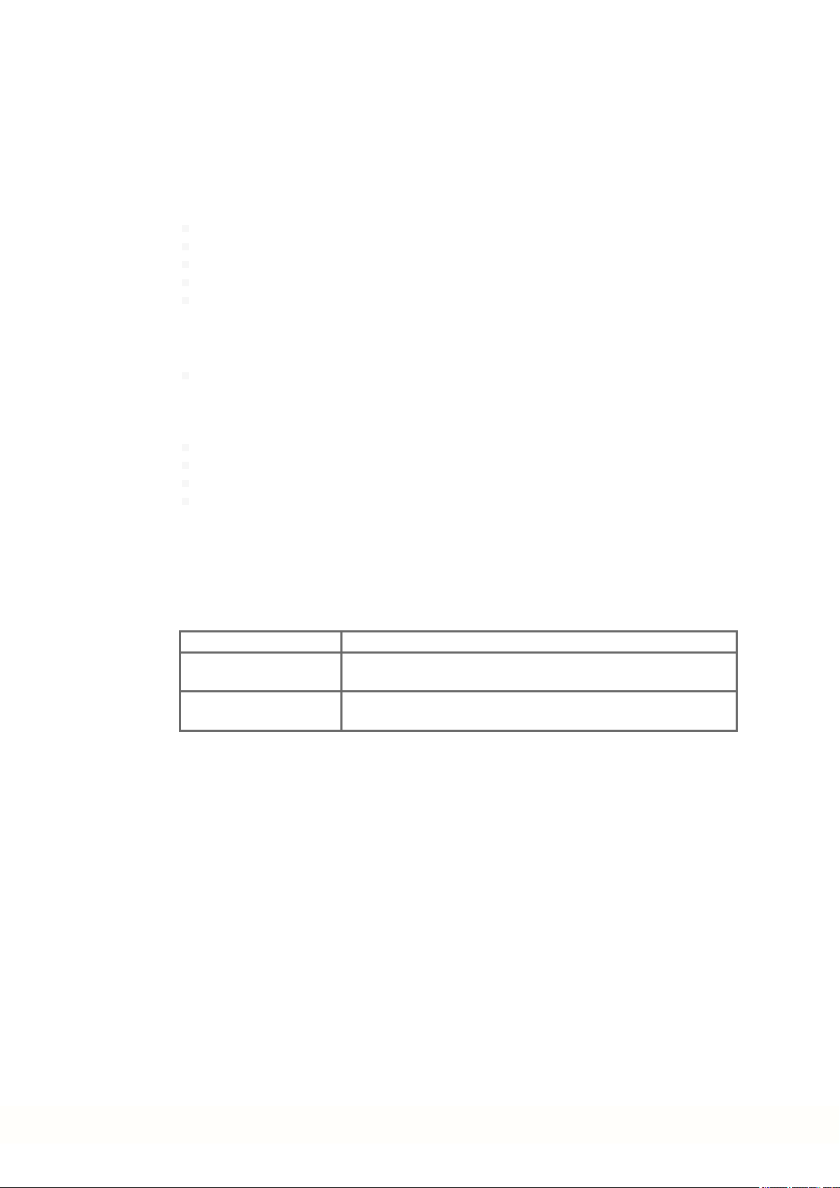
2.2 Using the PDF Format
This document includes several features for ease of navigation
Cross References Table of contents andindex include active cross references.
Table of contents and
index
Page/chapter numbers
in the text
Lines are active cross references. Click on the line andthe appropriate pageis accessed.
Page/chapternumbers with cross references areactive links.
10 Kollmorgen | kdn.kollmorgen.com | Beta, December 2018
2.3 Symbols Used
Warning Symbols
AKD2G-S Installation, Safety 1 | 2 General
Symbol Indication
Indicates a hazardous situation which, if not avoided, will result
in death or serious injury.
Indicates a hazardous situation which, if not avoided, could result in death or serious injury.
Indicates a hazardous situation which, if not avoided, could result in minoror moderate injury.
Indicates situations which, if not avoided, could result in property damage.
This symbol indicates important notes.
Warning of a danger (general). Thetype of danger is specified
by the text next to the symbol.
Warning of danger from electricity andits effects.
Warning of danger from hot surface.
Warning of danger from suspendedloads.
Warning of danger from automatic start.
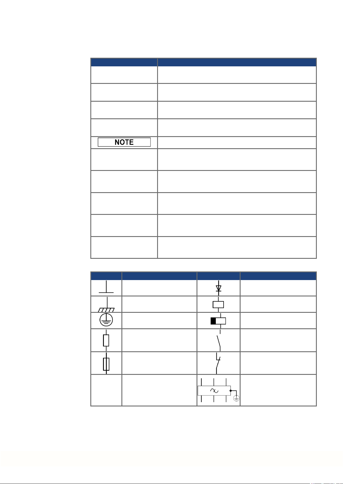
Drawing symbols
Symbol Description Symbol Description
Signal ground Diode
Chassis ground Relay
Protective earth Relay switch off delayed
Resistor Normally open contact
Fuse Normally closed contact
State-of-the-art firewall EMC filter
Kollmorgen | kdn.kollmorgen.com | Beta, December 2018 11

AKD2G-S Installation, Safety 1 | 2 General
2.4 Abbreviations Used
Abbreviations related to functional safety (➜ # 125).
Abbreviation Meaning
(➜ # 53) "see page53" in this document
Ω Ohms
A#, AXIS# A# or AXIS# are placeholders for the axis number. Used with keywords or
signal names
AGND Analog ground
AMSL Above mean sea level
Axis Depends on context, either one AKD2G output stageor one load axis of
the full motionsystem.
CAT Category
CE Communité Européenne
COM Serial interface for a personal computer
DGND Digital ground
EEPROM Electrically erasableprogrammable memory
EEO EmulatedEncoder Output
EMC Electromagnetic compatibility
EMF Electromagnetic force
F-SMA Fiber optic cable connector accordingto IEC 60874-2
FSoE Fail safe over EtherCAT
KAS Kollmorgen AutomationSuite
KAS IDE Setup software (Kollmorgen AutomationSuite Integrated Development
Environment)
KDN Kollmorgen Developer Network
LED Light-emitting diode
LSB Low significant byte (orbit)
MSB Main significant byte (or bit)
NI Zero pulse
OSSD Output Signal Switching Device
PC Personal computer
PE Protective earth
PELV Protective Extra Low Voltage
PLC Programmable logic control
PWM Pulse-width modulation
RAM Random access memory (volatile memory)
RBrake/RB Regenresistor (also calleda brake resistor)
RBext External regenresistor
RBint Internal regenresistor
RCD Residual current device
RES Resolver
S1 Continuous operation
tbd To be discussed (in process)
VAC Volts, alternatingcurrent
VDC Volts, direct current
12 Kollmorgen | kdn.kollmorgen.com | Beta, December 2018

2.5 Referred Standards
Standard Content
ISO 4762 Hexagon socket head cap screws
ISO 11898 Road vehicles — Controller area network (CAN)
ISO 12100 Safety of machinery: Basic concepts, general principles for design
ISO 13849 Safety of machinery: Safety-related parts of control systems
IEC 60085 Electrical insulation - Thermal evaluation and designation Maintenance
IEC 60204 Safety of Machinery: Electrical equipment of machinery
IEC 60364 Low-voltageelectrical installations
IEC 60439 Low-Voltage Switchgear andControlgear Assemblies
IEC 60529 International protection rating(IP code)
IEC 60664 Insulationcoordination for equipment within low-voltagesystems
IEC 60721 Classification of environmental conditions
IEC 61000 Electromagnetic compatibility (EMC)
IEC 61131 Programmable controllers
IEC 61784 Industrial communicationnetworks - Profiles,
IEC 61491 Electrical equipment of industrial machines – Serial data link for real-time
IEC 61508 Functional safety of electrical/electronic/programmableelectronic safety-
IEC 61800 Adjustable speedelectrical power drive systems
IEC 62061 Functional safety of electrical/electronic/programmableelectronic safety-
IEC 82079 Preparationof instructions for use - Structuring, content andpresentation
UL 61800-5-1 Adjustablespeed electrical powerdrive systems,
AKD2G-S Installation, Safety 1 | 2 General
Part 3-12 Functional safety fieldbuses
communications between controls and drives.
related systems
related systems
Safety Requirements – Electrical, Thermal, andEnergy
IEC - International Electrotechnical Commission
ISO - International Organizationfor Standardization
UL - Underwriters Laboratories
Kollmorgen | kdn.kollmorgen.com | Beta, December 2018 13

AKD2G-S Installation, Safety 1 | 3 Product Safety
3 Product Safety
3.1 You should pay attention to this 15
3.2 Shock-hazard Protection 17
3.3 Stop / Emergency Stop / Emergency Off 18
3.4 Warning note labels 20
3.5 Use as Directed 21
3.6 Prohibited Use 22
14 Kollmorgen | kdn.kollmorgen.com | Beta, December 2018

3.1 You should pay attention to this
This section helps to recognize risks and avoid dangers to people andobjects.
Specialist staff required!
Only properly qualified personnel arepermitted to perform such tasks as transport, installation and setup. Qualified specialist staff are persons with expertise in transport, installation,
assembly, commissioning and operation of electrotechnical equipment.
Transport, storage, unpacking: only by personnel with knowledge of handling electrostatically sensitive components.
Mechanical installation: only by personnel with mechanical expertise.
Electrical installation: only by personnel with electrotechnical expertise.
Basic tests / setup: only by personnel with expertise in electrical engineeringand drive
technology.
The qualified personnel must know and observe ISO 12100/ IEC 60364 / IEC 60664 and
national accident preventionregulations.
Read the documentation!
Read the available documentationbeforeinstallationand commissioning. Improperhandling
of the devices can cause harm to people or damage to property. The operatorof systems
using the drive system must ensure that all personnel who work with the drive read and understand the manual before using the drive.
AKD2G-S Installation, Safety 1 | 3 Product Safety
Check Hardware Revision!
Check the Hardware Revision Number of the product (see product label). This numberis the
link between your product andthe manual. The product Hardware Revision Number must
match the HardwareRevision Number onthe cover page of the manual.
Pay attention to the technical data!
Adhere to the technical data and the specifications on connection conditions. If permissible
voltage values or current values are exceeded, the devices can be damaged. Unsuitable
motororwrong wiring will damage the system components. Check the combination of drive
andmotor. Comparethe ratedvoltageand current of the units.
Perform a risk assessment!
The manufacturer of the machine must generate a risk assessment for the machine, andtake
appropriate measures to ensure that unforeseenmovements cannot cause injury or damage
to any person orproperty. Additional requirements on specialist staff may also result from the
risk assessment.
Automatic restart
The drive might restart automatically after power on, voltage dip or interruption of the supply
voltage, dependingon the parameter setting. Risk of death or serious injury for humans working in the machine.
If the parameterAXIS#.ENDEFAULT is set to 1, then place a warning sign to the machine
(Warning: Automatic Restart at Power On) and ensure, that power on is not possible, while
humans are in a dangerous zone of the machine. In case of using an undervoltageprotection
device, you must observe EN 60204-1:2006chapter 7.5 .
Kollmorgen | kdn.kollmorgen.com | Beta, December 2018 15

AKD2G-S Installation, Safety 1 | 3 Product Safety
Observe electrostatically sensitive components!
The devices contain electrostatically sensitive components which may be damaged by incorrect handling. Electrostatically discharge your body before touching the device. Avoid contact with highly insulatingmaterials (artificial fabrics, plastic film etc.). Place the device on a
conductive surface.
Hot surface!
Drives may have hot surfaces duringoperation. The housing can reach temperatures above
80°C. Risk of minor burns! Measurethe temperature, andwait until the housing has cooled
down below 40 °C before touchingit.
Earthing!
It is vital that you ensure that the drive is safely earthed to the PE (protective earth)busbarin
the switch cabinet. Risk of electric shock. Without low-resistance earthing no personal protection can be guaranteed.
Leakage Current!
Since the leakagecurrent to PE is more than3.5 mA, in compliance with IEC61800-5-1the
PE connection must eitherbe doubled or a connecting cable with a cross-section >10 mm²
must be used. Deviating measures according to regional standards might be possible.
High voltages!
The equipment produces highelectric voltages up to 900 V. Lethal danger exists at live parts
of the device. Do not open or touch the equipment duringoperation. Keep all covers and cabinet doors closed. Built-in protection measures such as insulation or shielding may not be
removed. Work on the electrical installation may only be performedby trainedand qualified
personnel, in compliance with the regulations for safety at work, and only with switchedoff
mains supply, and securedagainst restart.
Never undo any electrical connections to the drive while it is live. There is a danger of electrical arcing with damageto contacts and personal injury. Wait at least 5 minutes after disconnecting the drive from the main supply power before touching potentially live sections of
the equipment (such as contacts) or removing any connections.
Always measure the voltage in the DC bus link and wait until the voltage is below 50 V
before handling components.
Functional Safety!
Beta drives: Safety functionality is not approvednor certified. Do not use this functionality in
applications with functional safety request.
The assessment of the safety functions according to EN13849or EN 62061must finally be
done by the user.
Reinforced Insulation
Thermal sensors, motor holdingbrakes and feedback systems built into the connected motor
must have reinforced insulation(according to IEC61800-5-1) against system components
with powervoltage, accordingto the required application test voltage. All Kollmorgen components meet these requirements.
Never modify the drive!
It is not allowed to modify the drive hardwarewithout permission by the manufacturer. Opening the housing causes loss of warranty.
16 Kollmorgen | kdn.kollmorgen.com | Beta, December 2018
3.2 Shock-hazard Protection
3.2.1 Leakage current
Leakagecurrent via the PE conductor results from the combination of equipment and cable
leakage currents. Theleakagecurrent frequency patternincludes a number of frequencies,
whereby the residual-current circuit breakers definitively evaluate the 50 Hz current. For this
reason, the leakagecurrent cannot be measured using a conventional multimeter. Contact
ourapplication department for help to calculate the leakage current in your application.
Since the leakagecurrent to PE is more than3.5 mA, in compliance with IEC61800-5-1the
PE connection must eitherbe doubled or a connecting cable with a cross-section >10 mm²
must be used. Use the PE terminal and the PE connection screws in orderto fulfill this
requirement.
The followingmeasures can be used to minimize leakagecurrents:
Reduce the length of the engine cable.
Use low capacitance motor cables (➜ # 52).
3.2.2 Residual current protective device (RCD)
In conformity with IEC 60364-4-41 – Regulations for installationand IEC 60204– Electrical
equipment of machinery, residual current protective devices (RCDs) can be usedprovided
the requisite regulations arecomplied with. The AKD2G is a 3-phase system with a B6
bridge. Therefore, RCDs which aresensitive to all currents must be used in order to detect
any DC fault current.
Rated residual currents in the RCDs:
AKD2G-S Installation, Safety 1 | 3 Product Safety
10 to 30 mA Protection against "indirect contact" (personal fire protection)for stationary
50 to 300 mA Protection against "indirect contact" (personal fire protection) for stationary
Recommendation: In order to protect against direct contact (with motor cables shorter than
5 m) Kollmorgen recommends that each drive be protectedindividually using a 30 mA RCD
which is sensitive to all currents.
If you use a selective RCD, the more intelligent evaluation process will prevent spurious trippingof the RCD.
3.2.3 Isolating transformers
When protection against indirect contact is absolutely essential despite a higher leakage current, or when analternative form of shock-hazard protection is sought, the AKD2G can also
be operated via an isolating transformer. A ground-leakage monitorcan be usedto monitorfor
short circuits.
Keepthe length of wiring between the transformer andthe drive as short as possible.
andmobile equipment, as well as for "direct contact".
equipment
Kollmorgen | kdn.kollmorgen.com | Beta, December 2018 17
AKD2G-S Installation, Safety 1 | 3 Product Safety
3.3 Stop / Emergency Stop / Emergency Off
The control functions Stop, Emergency Stop andEmergency Off are defined by IEC 60204.
Notes for safety aspects of these functions can be found in ISO 13849and IEC 62061.
The parameterAXIS#.DISMODE must be set to implement the different stop categories.
Consult the WorkBench Online Help for configuring the parameter.
No functional safety!
Serious injury could result when the load is not properly blocked. With vertical load the load
could fall.
Functional safety, e.g. with hangingload (vertical axes), requires an additional mechanical brake which must be safely operated, for exampleby a safety control.
Set parameterAXIS#.MOTOR.BRAKEIMM to 1 with vertical axes, to apply the motor
holdingbrake (➜ # 82) immediately after faults or Hardware Disable.
3.3.1 Stop
The stop function shuts down the machinein normal operation. The stop function is defined
by IEC 60204.
The Stop Category must be determinedby a risk evaluation of the machine.
Stop function must have priority over assigned start functions. The following stop categories
aredefined:
Stop Category 0
Shut-down by immediate switching-off the energy supply to the drive machinery (this is an
uncontrolled shut-down). With the safety function STO (➜ # 127) the drive can be stopped
using its internal electronics (IEC 62061 SIL2).
Stop Category 1
A controlled shut-down, whereby the energy supply to the drive machinery is maintainedto
perform the shut-down, and the energy supply is only interrupted whenthe shut-down has
been completed.
Stop Category 2
A controlled shut-down, whereby the energy supply to the drive machinery is maintained.
Stop Category 0 and Stop Category 1 stops must be operableindependently of the operating
mode, whereby a Category 0 stop must have priority.
If necessary, provision must be made for the connection of protective devices and lock-outs.
If applicable, the stop function must signal its status to the control logic. A reset of the stop
function must not create a hazardous situation.
18 Kollmorgen | kdn.kollmorgen.com | Beta, December 2018
3.3.2 Emergency Stop
The Emergency Stop function is used for the fastest possible shutdown of the machine in a
dangerous situation. The Emergency Stop function is defined by IEC 60204. Principles of
emergency stop devices and functional aspects are defined in ISO 13850.
The Emergency Stop function will be triggeredby the manual actions of a single person. It
must be fully functional and available at all times. The user must understandinstantly how to
operate this mechanism (without consulting references or instructions).
The Stop Category for the Emergency Stop must be determinedby a risk evaluation of the
machine.
In additionto the requirements for stop, the Emergency Stop must fulfil the following requirements:
Emergency Stop must have priority over all otherfunctions andcontrols in all operating
modes.
The energy supply to any drive machinery that could cause dangerous situations must be
switched off as fast as possible, without causing any further hazards (Stop Category 0)
or must be controlledin such a way, that any movement that causes danger, is stopped
as fast as possible (Stop Category 1).
The reset must not initiate a restart.
AKD2G-S Installation, Safety 1 | 3 Product Safety
3.3.3 Emergency Off
The Emergency Off function is used to switch-off the electrical power supply of the machine.
This is done to prevent users from any risk from electrical energy (for example electrical
impact). Functional aspects for Emergency Off aredefinedin IEC 60364-5-53.
The Emergency Off function will be triggeredby the manual actions of a single person.
The result of a risk evaluation of the machine determines the necessity for an Emergency
Off function.
Emergency Off is doneby switching off the supply energy by electro-mechanical switching
devices. This results in a category 0 stop. If this stop category is not possible in the application, then the Emergency Off function must be replaced by other measures (for example by
protection against direct touching).
Kollmorgen | kdn.kollmorgen.com | Beta, December 2018 19

AKD2G-S Installation, Safety 1 | 3 Product Safety
3.4 Warning note labels
If a warningnote label is damaged, it must be replaced immediately.
3.4.1 Notes placed on the product
AKD2G
Wait 5 minutes
after removing power
before servicing.
3.4.2 Adhesive label in the package
To meet UL, place the multi-languagelabel on the drive or on the panel near the drive.
20 Kollmorgen | kdn.kollmorgen.com | Beta, December 2018

3.5 Use as Directed
The AKD2G drives are exclusively intended for drivingsuitablesynchronous servomotors
with closed-loopcontrol of torque, speed, and/or position.
AKD2G are components that are built into electrical plants or machines and can only be operated as integral components of these plants or machines. The manufacturer of the machine
used with a drive must generate a risk assessment for the machine. When the drives arebuilt
into machines or plant, the drive must not be used until it has beenestablished that the
machine or plant fulfills the requirements of the regional directives.
Cabinet and wiring
Drives must only be operated in a closed control cabinet suitable for the ambient conditions
(➜ # 33). Ventilationor cooling may be necessary to keep the temperature within the cabinet
below 40°C.
Use only copper conductors for wiring. The conductor cross-sections can be derived from the
standard IEC 60204 (alternatively for AWG cross-sections: NEC Table 310-16, 75°C
column).
Power supply
The drives can be supplied by 1, 2 or 3 phase industrial supply networks.
Drives in the AKD2G series can be suppliedas follows:
AKD2G-S Installation, Safety 1 | 3 Product Safety
AKD2G-Sxx-6Vxx:
1, 2 or 3 phase industrial supply networks (not morethan200 kA symmetrical rated current at 120 V and 240V).
AKD2G-Sxx-7Vxx:
3 phase industrial supply networks (not more than200 kA symmetrical ratedcurrent at
240V, 400 V and480 V).
Connection to other voltage types of supply networks is possible with an additional isolating
transformer.
Repeated overvoltages betweenphases (L1, L2, L3) and the housingof the drive must not
exceed1000 V peak. In accordance with IEC 61800, voltagespikes (< 50 µs) between
phases must not exceed1000 V. Voltagespikes (<50µs) between a phase and the housing
must not exceed 2000 V.
EMC filter measures for AKD2G-Sxx-6Vxx must be implemented by the user.
Motor voltage rating
The rated voltage of the motors must be at least as high as the DC bus link voltage divided
by √2 produced by the drive (U
nMotor
>=UDC/√2).
Functional Safety
Beta Drives: Safety functionality is neither approved norcertified yet. Do not use this functionality in applications with functional safety request until further notice.
The network, to which the drive is connected, must be secured according to state-of-theart information technology security requirements.
The userIT specialists shall analyze whetherfurther security requirements are applicableto ensure functional safety.
Review the chapter"Use as Directed" in the Functional Safety section (➜ # 123)before
using safety functionality.
Kollmorgen | kdn.kollmorgen.com | Beta, December 2018 21

AKD2G-S Installation, Safety 1 | 3 Product Safety
3.6 Prohibited Use
Otheruse thanthat described in chapter “Use as directed” is not intended and can lead to personnel injuries andequipment damage. The drive may not be used with a machine that does
not comply with appropriate national directives or standards. The use of the drive in the following environments is also prohibited:
potentially explosive areas
environments with corrosive and/or electrically conductive acids, alkaline solutions, oils,
vapors, dusts
ships or offshore applications
The drive must not be connected directly to the Internet. If the network, to which the drive is
connected, is not secured according to state-of-the-art information technology, this could be
a functional safety risk.
22 Kollmorgen | kdn.kollmorgen.com | Beta, December 2018

AKD2G-S Installation, Safety 1 | 4 Product life cycle handling
4 Product life cycle handling
4.1 Transport 24
4.2 Packaging 24
4.3 Storage 24
4.4 Installation, setup and normal operation 25
4.5 Decommissioning 25
4.6 Maintenance and cleaning 25
4.7 Disassembly 25
4.8 System Repair 26
4.9 Disposal 26
Kollmorgen | kdn.kollmorgen.com | Beta, December 2018 23
AKD2G-S Installation, Safety 1 | 4 Product life cycle handling
4.1 Transport
Transport the AKD2G in accordance with IEC 61800-2 as follows:
Transport only by qualifiedpersonnel in the manufacturer’s original recyclablepackaging.
Avoid shocks while transporting.
Vibration/Shock: AKD2G is tested for environmental class 2M1 of IEC 60721-3-2.
Store at or below maximum stacking height 8 cartons (see "Storage" (➜ # 24))
Transport only within specified temperatureranges:
-25to +70 °C, max. rate of change 20K/hour, class 2K3.
Transport only within specified humidity:
max. 95% relative humidity at +40°C, no condensation, class 2K3.
The drives containelectrostatically sensitive components that can be damaged by incorrect
handling. Electrostatically dischargeyourself beforetouching the drive. Avoid contact with
highly insulating materials, such as artificial fabrics and plastic films. Place the drive on a
conductive surface.
If the packagingis damaged, check the unit for visible damage. Inform the shipperand the
manufacturer of any damageto the package orproduct.
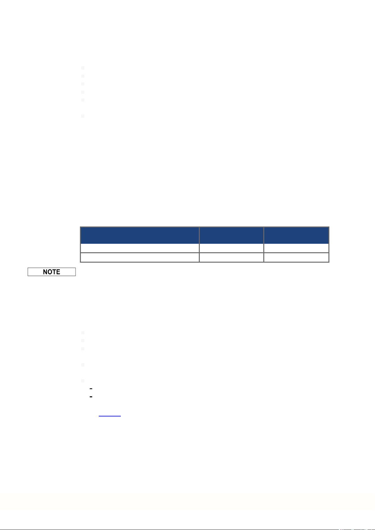
4.2 Packaging
4.3 Storage
The AKD2G packaging consists of recyclable cardboard with inserts and a label on the outside of the box.
Model Package
(mm) HxWxL
AKD2G-Sxx-6V03 to 6V12 tbd 4.2
AKD2G-Sxx-7V03 to 7V12 tbd 4.3
Matingconnectors arenot included in the packageof a standarddrive.
Matingconnectors areincluded whenthe drive is orderedwith accessories (append “-A”to
the model number).
Store the AKD2G in accordance with IEC 61800-2 as follows:
Store only in the manufacturer’s original recyclable packaging.
Store at or below maximum stacking height 8 cartons.
Store only within specified temperature ranges: -25to +55 °C, max.rate of change
20K/hour, class 1K4.
Storage only within specified humidity: 5 to 95% relative humidity, no condensation, class
1K3.
Store in accordance with the following durationrequirements:
Less than 1 year: without restriction.
More than 1 year: capacitors must be re-formed before setting up and operating the
drive. Re-forming procedures aredescribedin the KollmorgenDeveloper Network
(Forming).
Total Weight
(kg)
24 Kollmorgen | kdn.kollmorgen.com | Beta, December 2018

AKD2G-S Installation, Safety 1 | 4 Product life cycle handling
4.4 Installation, setup and normal operation
Installation andsetup informationare given in this manual:
Mechanical installation (➜ # 45)
Electrical installation(➜ # 48)
Setup (➜ # 111)
Normal operation tested for environmental class 3K3 according to IEC 61800-2(➜ # 33).
The manufacturer of the machine defines the necessary enduser expertise basedonthe risk
assessment for the machine and describes the requirements for normal operation based on
the application.
4.5 Decommissioning
Only professional staff who arequalified in electrical engineering are allowed to decommission parts of the system.
DANGER: Lethal Voltages!
There is a dangerof serious personal injury or death by electrical shock or electrical arcing.
Switch off the main switch of the switchgear cabinet.
Securethe system against restarting.
Block the main switch.
Wait at least 5 minutes after disconnecting.
4.6 Maintenance and cleaning
The device does not require maintenance. Opening the device voids the warranty. The inside
of the unit can only be cleanedby the manufacturer.
Do not immerse or spray the device. Avoid that liquid enters the device.
To clean the device exterior:
1. Decommission the device (see chapter 4.5 "Decommissioning").
2. Casing: Clean with isopropanol or similar cleaning solution.
Caution : Highly Flammable! Risk of injury by explosionand fire.
Observe the safety notes given on the cleaning liquidpackage.
Wait at least 30 minutes after cleaningbeforeputting the device back into operation.
3. Protective grill on fan: Clean with a dry brush.
4.7 Disassembly
Only professional staff who arequalified in electrical engineering are allowed to disassemble
parts of the system.
1. Decommission the device (see chapter 4.5 "Decommissioning").
2. Check temperature.
CAUTION: High Temperature! Risk of minor burns. During operation, the heat sink of
the drive may reach temperatures above 80°C (176°F). Before touching the device,
check the temperature andwait until it has cooled below 40°C (104°F).
3. Remove the connectors. Disconnect the potential earth connection last.
4. Demount: loosen the fastening screws. Remove the device.
Kollmorgen | kdn.kollmorgen.com | Beta, December 2018 25
AKD2G-S Installation, Safety 1 | 4 Product life cycle handling
4.8 System Repair
Only professional staff who arequalified in electrical engineering are allowed to exchange
parts of the drive system.
CAUTION: Automatic Start! During replacement work a combination of hazards andmul-
tiple episodes may occur.
Work on the electrical installationmay only be performed by trained andqualified personnel, in compliance with the regulations for safety at work, andonly with use of prescribed personal safety equipment.
Exchange of the device
Only the manufacturercan repairthe device. Opening the device voids the warranty.
1. Decommission the device (see chapter 4.5 "Decommissioning").
2. Demount the device (see chapter4.7 "Disassembly").
3. Send the device to the manufacturer.
4. Install a new device as described in this manual.
5. Setup the system as described in this manual.
Exchange of other drive system parts
If parts of the drive system (forexample cables) must be replaced, proceed as follows:
4.9 Disposal
1. Decommission the device (see chapter 4.5 "Decommissioning").
2. Exchange the parts.
3. Check all connections for correct fastening.
4. Setup the system as described in this manual.
To dispose the unit properly, contact a certified electronic scrap disposal merchant.
In accordance with the WEEE-2012/19/EC guidelineand similar, the manufacturer accepts
returns of old devices and accessories for professional disposal. Transport costs are the
responsibility of the sender.
Contact Kollmorgen andclarify the logistics.
Sendthe devices in the original packaging to the manufacturer address:
North America South America
KOLLMORGEN
201West Rock Road
Radford, VA 24141, USA
Europe Asia
KOLLMORGEN Europe GmbH
Pempelfurtstr. 1
40880Ratingen, Germany
KOLLMORGEN
AvenidaJoãoPaulo Ablas, 2970
Jardim da Glória, Cotia – SP
CEP 06711-250, Brazil
KOLLMORGEN
Floor 4, Building 9, No. 518,
North FuquanRoad, Changning District,
Shanghai 200335, China
26 Kollmorgen | kdn.kollmorgen.com | Beta, December 2018

AKD2G-S Installation, Safety 1 | 5 Package
5 Package
5.1 Package Supplied 28
5.2 Nameplate 28
5.3 Part Number Scheme 29
Kollmorgen | kdn.kollmorgen.com | Beta, December 2018 27

AKD2G-S Installation, Safety 1 | 5 Package
5.1 Package Supplied
When a standard drive from the AKD2G series is delivered, the following items areincluded
in the drive package:
AKD2G
Printedcopy of AKD®2G Product Safety Guide .
DVD with WorkBench setup software .
Panel safety label
Matingconnectors arenot included in the packageof a standarddrive.
Matingconnectors areincluded whenthe drive is orderedwith accessories (append “-A”to
the model number). With the accessories option all connectors to match the drive variant are
included, excepting SubD (Feedback 3), RJ25 (CAN bus) andRJ45 (service and fieldbus
networks).
Accessories Sold Separately
Accessories must be ordered separately if required.
EMC filters for mains supply voltage, categories C2 or C3.
External regenresistor.
Connector kits
Hybrid cable. Assembled hybridmotor cables are available for all regions.
Motorcable. Assembledmotor cables are available for all regions.
Feedback cable. Assembled feedback cables areavailable for all regions.
SFA (Smart Feedback Adapter) .
SDB Module (Safe Dynamic Brake Module).
Ethernet service cable.
5.2 Nameplate
A nameplate is attached to the side of the drive. The picturebelow is similar to the nameplate
on the device.
28 Kollmorgen | kdn.kollmorgen.com | Beta, December 2018

5.3 Part Number Scheme
Use the part numberscheme for product identification only, not for the order process,
because not all combinations of features are possible.
Matingconnectors arenot included in the packageof a standarddrive.
Matingconnectors areincluded whenthe drive is orderedwith accessories (append “-A”to
the model number).
AKD2G-S Installation, Safety 1 | 5 Package
Example AKD2G-SPE-7V06S-A1IO-0000
AKD2G IP20 housing, position indexer, EtherCAT, 240 V to 480 V mains supply, 6 A rated
current, single axis, HardwareRevision A, dual channel STO SIL2 PLd, with additional I/O
connector X22, uncoated, no mating connectors.
Example AKD2G-SPE-6V03D-A1DX-A000-A
AKD2G IP20 housing, position indexer, EtherCAT, 120 V to 240 V mains supply, 2 x 3 A
rated current, dual axis, HardwareRevision A, dual channel STO SIL2 PLd, with all possible
connector (basis + X23), PCBs coated, with mating connectors.
Kollmorgen | kdn.kollmorgen.com | Beta, December 2018 29

AKD2G-S Installation, Safety 1 | 6 Technical description anddata
6 Technical description and data
6.1 The AKD2G Family of Digital Drives 31
6.2 Ambient Conditions, Ventilation, and Mounting Position 33
6.3 Mechanical Data 33
6.4 Performance Data 34
6.5 Electrical data 35
6.6 LCD Display and Push-buttons (B1, B2) 39
6.7 SD Card Slot 41
6.8 Electrical Motor Braking 42
30 Kollmorgen | kdn.kollmorgen.com | Beta, December 2018
 Loading...