

Kollmorgen AKD2G-S, AKD2G, AKD2G-S-7V03, AKD2G-S-7V12, AKD2G-S-6V03 Product Safety Manual
...Page 1

AKD®2G-Sxx
Product Safety Guide
Edition: -, Beta, December 2018
Valid for AKD2G, Hardware Revision A
Part Number 907-200024-99
English Deutsch Français Italiano Português Español Русский 中 国
Original language is English. All other content is translated from the genuine English content.
Forsafe and proper use, follow
these instructions.
Keepthem for futurereference.
Beta Drives: Approvals (CE, Functional Safety, UL) are pending.
Page 2
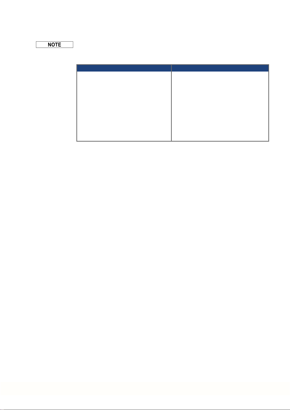
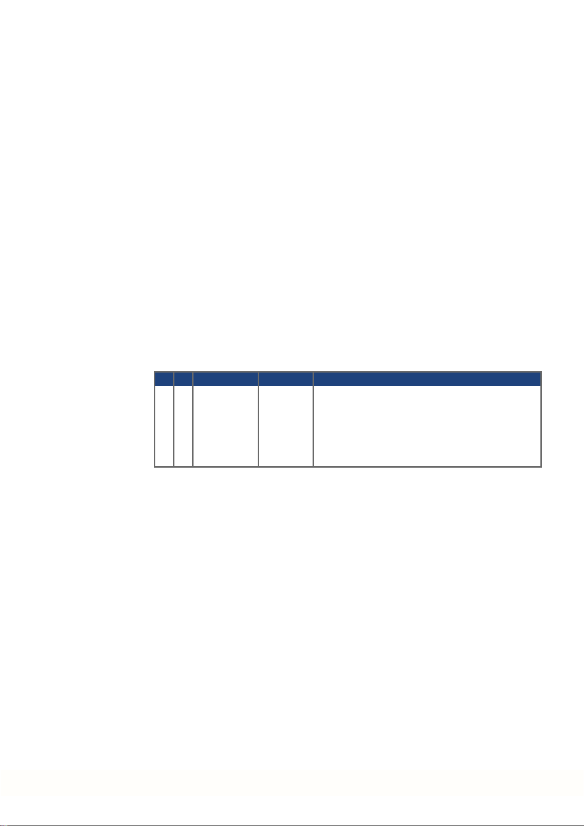
Record of Document Revisions
Revision Remarks
...
Table with lifecycle informationof this document see (➜ # 75)
Beta, 12/2018 Beta edition
Contents
Product Safety Guide English (➜ # 3) Product Safety Guide Português (➜ # 49)
Product Safety Guide Deutsch (➜ # 25) Product Safety Guide Español (➜ # 50)
Product Safety Guide Français (➜ # 47) Product Safety GuideРусский (➜ # 51)
Product Safety Guide Italiano (➜ # 48)
Product Safety Guide 中国
(➜ # 52)
Appendix/Electrical Data (➜ # 54) Appendix/Dimensions (➜ # 60)
Appendix/Connection Overview (➜ # 61) Appendix/Approvals (➜ # 74)
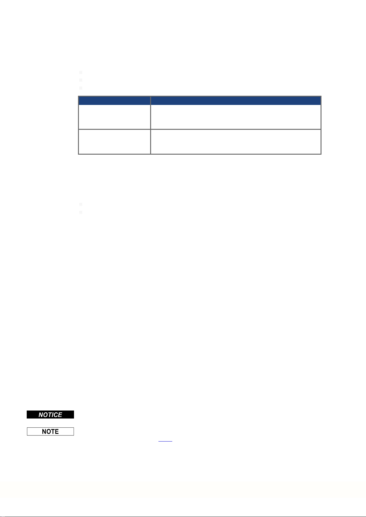
Hardware Revision (HR)
AKD2G Firmware Workbench KAS IDE Remarks
A from 02-00-00-000 from 2.00.0.0000 from 3.01 Beta revision
Technical changes which improve the performance of the device may be made without prior notice!
This document is the intellectual property of Kollmorgen. All rights reserved. No part of this work may be reproduced
in any form (by photocopying, microfilm or any other method) or stored, processed, copied or distributed by electronic
means without the written permission of Kollmorgen.
Technische Änderungen zur Verbesserung der Leistung der Geräte ohne vorherige Ankündigung vorbehalten.
Dieses Dokument ist geistiges Eigentum von Kollmorgen. Alle Rechte vorbehalten. Kein Teil dieses Werkes darf in
irgendeiner Form (Fotokopie, Mikrofilm oder in einem anderenVerfahren) ohne schriftliche Genehmigung von Kollmorgen reproduziert oder elektronisch verarbeitet, vervielfältigt oder verbreitet werden.
Sous réserve de modifications techniques apportés en vue d'amélioration des appareils!
Ce document est la propriété intellectuelle de Kollmorgen.Tous droits réservés. Sans autorisation écrite de
l'entreprise Kollmorgen, aucune partie de cet ouvrage n'a le droit d'être ni reproduite par des moyens quelconques
(impression, photocopie, microfilm ou autre procédure) ni traitée, polycopiée ou distribuée électronique.
Il produttore si riserva la facoltà di apportare modifiche tecniche volte al miglioramento degli apparecchi
Questo documento è la proprietà intellettuale di Kollmorgen. Tutti i diritti riservati. Nessuna parte del documento può
essere riprodotta in qualsiasi forma (fotocopia, microfilm o altro processo) senza l’approvazione scritta della ditta Kollmorgen o rielaborata, riprodotta o diffusa mediante l’uso di sistemi elettronici.
Alterações técnicas que melhoram o desempenho do dispositivo podem ser feitos sem aviso prévio!
Este documento é uma propriedade intelectual da Kollmorgen. Todos os direitos reservados. Nenhuma parte deste
trabalho pode ser reproduzida sob qualquer forma (por fotocópia, microfilme ou qualquer outro método) ou
armazenado, processado, copiado ou distribuído por meios eletrônicos sem a permissão escrita da Kollmorgen.
Los cambios técnicos que mejoran el rendimiento del dispositivo pueden llevarse a cabo sin aviso previo.
Este documento es propiedad intelectual de Kollmorgen. Todos los derechos reservados. Ninguna parte de esta
obra, bajo concepto alguno, podrá reproducirse (por fotocopia, microfilm ni ningún otro método) ni almacenarse, procesarse, copiarse ni distribuirse por medios electrónicos sin el permiso por escrito de Kollmorgen.
Сохраняется право внесения технических изменений с целью усовершенствования приборов!
Настоящий документ является интеллектуальной собственностью Kollmorgen. Все права защищены.
Воспроизведение любой части данного издания в любой форме (фотокопия, микрофильм или иной метод) или
редактирование, размножение или распространение с помощью электронных систем без письменного
разрешения компании Kollmorgen запрещаются.
如有提升设备性能的技术变更,恕不另行通知!
本文档知识产权归 Kollmorgen 所有 。版 权所 有 。未 经 Kollmorgen 书面许可,不得以任何形式( 利 用 影 印 、缩 微 胶
片或任何其他方法) 复 制 本 文 档 的 任 何 部 分 ,也 不 得 利 用 电 子 手 段 存 储 、处 理 、复制或分发本文 档 的 任 何 部 分 。
2 Kollmorgen | kdn.kollmorgen.com | Beta, December 2018
Page 3

AKD2G Product Safety Guide | 1 English
1 English
1.1 General 4
1.1.1 Notes for the PrintedEdition (paper version) 4
1.1.2 Symbols Used 5
1.1.3 Abbreviations Used 6
1.2 Product Safety 7
1.2.1 You should pay attention to this 7
1.2.2 Use as Directed 9
1.2.3 ProhibitedUse 10
1.2.4 Warning note labels 11
1.3 Product life cycle handling 12
1.3.1 Transport 12
1.3.2 Packaging 12
1.3.3 Storage 12
1.3.4 Installation, setup and normal operation 13
1.3.5 Decommissioning 13
1.3.6 Maintenance and cleaning 13
1.3.7 Disassembly 13
1.3.8 System Repair 14
1.3.9 Disposal 14
1.4 Technical description and general data 15
1.4.1 Drive part number scheme 15
1.4.2 PackageSupplied 16
1.4.3 Ambient Conditions, Ventilation, andMounting Position 16
1.4.4 Electrical Data 17
1.4.5 Display, B1/2 push-buttons, S1/2 rotary switches 17
1.4.6 Fault and Warning Messages 18
1.5 Functional Safety 19
1.6 Mechanical Installation 20
1.7 Electrical Installation 21
1.8 Setup 22
1.9 Troubleshooting the AKD2G 24
Kollmorgen | kdn.kollmorgen.com | Beta, December 2018 3
Page 4
AKD2G Product Safety Guide | 1 English
1.1 General
This guide presents the relevant information forsafe installation andsetup of the AKD®2G
series of digital drives with functional safety support. This guideis valid for AKD®2G single
axis drive or dual axis drive with 110V to 240V or 240V to 480V mains voltage.
Ouput stages: 3 A, 6 A, 12A rated current
Programmability options: Base drive or Position Indexer drive
Connectivity options: analog, CANopen, EtherCAT
I/O options: Extended I/O (X22), 2ndFeedback&EEO (X23)
Functional Safety options:
safety option 1 (SIL2 PLd) with STO or
safety option 2 (SIL3 PLe) with STO, SS1-t, SBC, SDB and SBT or
safety option 3 (SIL3 PLe) with STO, SS1-t, SS1-r, SS2, SLS, SSM, SSR, SDI, SLA,
SAR, SLI, SLP, SCA, SBC, SDB and SBT.
Forfull informationrefer to additional Kollmorgendocuments for the AKD2G series of drives:
Installation Manual (PDF format):
This manual provides instructions for installationand drive setup.
Accessories Manual (PDF format):
It provides informationfor accessories like cables andregen resistors used with AKD2G.
Regional variants of this manual exist.
CAN-BUS Communication (PDF format):
Describes how to use your drive in CANopen applications.
EtherCAT Communication (PDF format):
Describes how to use your drive in EtherCAT applications.
WorkBench Online help (HTML5 format):
Describes how to use your drive in common applications. It also provides tips for maximizing yoursystem performance with the AKD2G. The online help includes the Para-
meter and Command Reference Guide which provides information for the parameters and
commands used to program the AKD2G.
Beta Drives:
Approvals (CE, Functional Safety, UL) are pending.
All documents are in preliminary.
These documents can be found on the DVD in the drive package. All documents can be
downloadedfrom the Kollmorgen website www.kollmorgen.com.
1.1.1 Notes for the Printed Edition (paper version)
A printed version of the manual is enclosed with each product. For
environmental reasons, the document was reduced in size and printed on DINA5.
Shouldyou experience difficulties reading the font size of the
scaled-down printed version, you can print and usethe PDF versionin DINA4 format 1:1. Youcan find the PDFversion on the
DVD accompanying the product and on the Kollmorgen website.
4 Kollmorgen | kdn.kollmorgen.com | Beta, December 2018
Page 5
1.1.2 Symbols Used
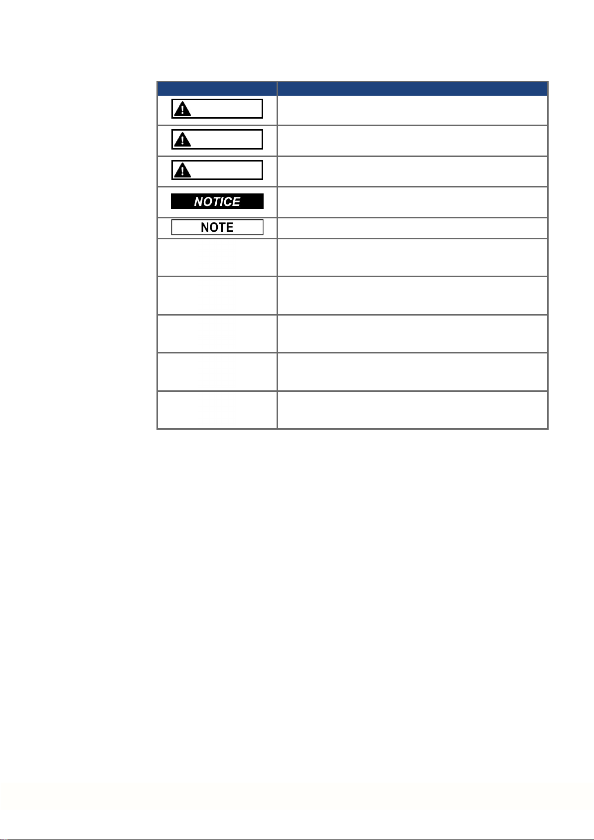
Symbol Indication
DANGER
Indicates a hazardous situation which, if not avoided, will result in death or serious injury.
AKD2G Product Safety Guide | 1 English
WARNING
CAUTION
Indicates a hazardous situation which, if not avoided, could
result in death or serious injury.
Indicates a hazardous situation which, if not avoided, could
result in minor or moderate injury.
Indicates situations which, if not avoided, could result in property damage.
This symbol indicates important notes.
Warning of a danger (general). The type of danger is specified
by the text next to the symbol.
Warning of danger from electricity andits effects.
Warning of danger from hot surface.
Warning of danger from suspended loads.
Warning of danger from automatic start.
Kollmorgen | kdn.kollmorgen.com | Beta, December 2018 5
Page 6

AKD2G Product Safety Guide | 1 English
1.1.3 Abbreviations Used
Abbreviation Meaning
(➜ # 53) "see page 53" in this document
Ω Ohms
A#, AXIS# A# or AXIS# are placeholders for the axis number. Used with keywords or
signal names
AGND Analog ground
AMSL Above meansealevel
Axis Depends on context, eitherone AKD2G output stageor one loadaxis of
the full motion system.
CAT Category
CE Communité Européenne
COM Serial interface for a personal computer
DGND Digital ground
EEPROM Electrically erasable programmablememory
EEO EmulatedEncoder Output
EMC Electromagnetic compatibility
EMF Electromagnetic force
F-SMA Fiber optic cableconnector according to IEC 60874-2
FSoE Fail safe over EtherCAT
KAS Kollmorgen AutomationSuite
KAS IDE Setup software (Kollmorgen Automation Suite Integrated Development
Environment)
KDN Kollmorgen Developer Network
LED Light-emitting diode
LSB Low significant byte (or bit)
MSB Main significant byte (orbit)
NI Zero pulse
OSSD Output Signal Switching Device
PC Personal computer
PE Protective earth
PELV Protective Extra Low Voltage
PLC Programmable logic control
PWM Pulse-width modulation
RAM Random access memory (volatile memory)
RBrake/RB Regenresistor (also called a brake resistor)
RBext External regenresistor
RBint Internal regen resistor
RCD Residual current device
RES Resolver
S1 Continuous operation
tbd To be discussed (inprocess)
VAC Volts, alternating current
VDC Volts, direct current
6 Kollmorgen | kdn.kollmorgen.com | Beta, December 2018
Page 7

1.2 Product Safety
1.2.1 You should pay attention to this
Specialist staff required!
Only properly qualified personnel are permitted to perform such tasks as transport, installation and setup. Qualified specialist staff are persons with expertise in transport, installation,
assembly, commissioning and operation of electrotechnical equipment.
Transport, storage, unpacking: only by personnel with knowledge of handling electrostatically sensitive components.
Mechanical installation: only by personnel with mechanical expertise.
Electrical installation: only by personnel with electrotechnical expertise.
Basic tests / setup: only by personnel with expertise in electrical engineering and drive
technology.
The qualifiedpersonnel must know andobserve ISO 12100 / IEC 60364 / IEC 60664and
national accident prevention regulations.
Read the documentation!
Read the availabledocumentation beforeinstallation and commissioning. Improperhandling
of the devices can cause harm to people ordamage to property. The operator of systems
using the drive system must ensurethat all personnel who work with the drive readand understand the manual before usingthedrive.
AKD2G Product Safety Guide | 1 English
Check Hardware Revision!
Check the HardwareRevision Number of the product (seeproduct label). This numberis the
link between your product and the manual. The product HardwareRevision Number must
match the Hardware Revision Number on thecoverpage of the manual.
Pay attention to the technical data!
Adhereto the technical data and the specifications on connection conditions. If permissible
voltage values or current values are exceeded, the devices can be damaged. Unsuitable
motoror wrong wiring will damage the system components. Check the combination of drive
andmotor. Compare the rated voltageandcurrent of the units.
Perform a risk assessment!
The manufacturerof the machine must generate a risk assessment for the machine, andtake
appropriate measures to ensure that unforeseenmovements cannot cause injury or damage
to any person orproperty. Additional requirements onspecialist staff may also result from the
risk assessment.
Automatic restart
The drive might restart automatically after power on, voltage dipor interruption of the supply
voltage, depending ontheparametersetting. Risk of death orserious injury for humans working in the machine.
If the parameterAXIS#.ENDEFAULT is set to 1, then place a warningsign to the machine
(Warning: Automatic Restart at Power On)and ensure, that power onis not possible, while
humans are in a dangerous zone of the machine. In case of using anundervoltage protection
device, you must observe EN 60204-1:2006 chapter 7.5 .
Kollmorgen | kdn.kollmorgen.com | Beta, December 2018 7
Page 8

AKD2G Product Safety Guide | 1 English
Observe electrostatically sensitive components!
The devices contain electrostatically sensitive components which may bedamaged by incorrect handling. Electrostatically discharge your body before touching the device. Avoid contact with highly insulatingmaterials (artificial fabrics, plastic film etc.). Place the device on a
conductive surface.
Hot surface!
Drives may have hot surfaces during operation. The housing can reach temperatures above
80°C. Risk of minorburns! Measure the temperature, and wait until the housing has cooled
down below 40 °C before touching it.
Earthing!
It is vital that you ensure that the drive is safely earthed to the PE (protective earth) busbarin
the switch cabinet. Risk of electric shock. Without low-resistance earthing nopersonal protection can be guaranteed.
Leakage Current!
Since the leakage current to PE is more than 3.5 mA, in compliance with IEC61800-5-1 the
PE connection must either bedoubledor a connecting cable with a cross-section >10 mm²
must be used. Deviating measures accordingto regional standards might be possible.
High voltages!
The equipment produces highelectric voltages up to 900 V. Lethal dangerexists at live parts
of the device. Do not open or touch the equipment during operation. Keepall covers and cabinet doors closed. Built-in protection measures such as insulation orshieldingmay not be
removed. Work on the electrical installation may only be performedby trained and qualified
personnel, in compliance with the regulations for safety at work, and only with switched off
mains supply, and secured against restart.
Never undo any electrical connections to the drive while it is live. There is a danger of electrical arcingwith damageto contacts andpersonal injury. Wait at least 5 minutes after disconnecting the drive from the main supply powerbefore touching potentially live sections of
the equipment (such as contacts) or removing any connections.
Always measure thevoltage in the DC bus link andwait until the voltage is below 50 V
before handling components.
Functional Safety!
Beta drives: Safety functionality is not approvednor certified. Do not use this functionality in
applications with functional safety request.
The assessment of the safety functions accordingto EN13849 or EN 62061 must finally be
done by the user.
Reinforced Insulation
Thermal sensors, motor holdingbrakes andfeedback systems built into the connected motor
must have reinforcedinsulation (according to IEC61800-5-1) against system components
with power voltage, accordingto the requiredapplication test voltage. All Kollmorgen components meet these requirements.
Never modify the drive!
It is not allowed to modify the drive hardware without permission by the manufacturer. Opening the housingcauses loss of warranty.
8 Kollmorgen | kdn.kollmorgen.com | Beta, December 2018
Page 9

1.2.2 Use as Directed
The AKD2G drives are exclusively intended for driving suitablesynchronous servomotors
with closed-loop control of torque, speed, and/orposition.
AKD2G arecomponents that arebuilt into electrical plants or machines andcanonly be operated as integral components of these plants or machines. Themanufacturer of the machine
used with a drive must generate a risk assessment for the machine. When the drives are built
into machines or plant, the drive must not be used until it has been established that the
machine or plant fulfills the requirements of the regional directives.
Cabinet and wiring
Drives must only be operatedin a closed control cabinet suitable for the ambient conditions
(➜ # 16). Ventilation or cooling may be necessary to keep the temperaturewithin the cabinet
below 40°C.
Use only copperconductors for wiring. The conductor cross-sections can bederived from the
standard IEC 60204 (alternatively for AWG cross-sections: NEC Table 310-16, 75°C
column).
Power supply
The drives can be supplied by 1, 2 or3phase industrial supply networks.
Drives in the AKD2G series can besupplied as follows:
AKD2G Product Safety Guide | 1 English
AKD2G-Sxx-6Vxx:
1, 2 or 3 phase industrial supply networks (not morethan 200 kA symmetrical ratedcurrent at 120 V and 240 V).
AKD2G-Sxx-7Vxx:
3 phase industrial supply networks (not morethan200 kA symmetrical rated current at
240V, 400 V and 480 V).
Connection to othervoltage types of supply networks is possible with an additional isolating
transformer.
Repeated overvoltages betweenphases (L1, L2, L3)and the housing of the drive must not
exceed1000V peak. In accordance with IEC 61800, voltagespikes (< 50 µs) between
phases must not exceed 1000 V. Voltage spikes (<50 µs) between a phase and the housing
must not exceed 2000 V.
EMC filter measures for AKD2G-Sxx-6Vxx must beimplemented by the user.
Motor voltage rating
The rated voltage of the motors must be at least as highas the DC bus link voltagedivided
by √2 produced by the drive (U
nMotor
>=UDC/√2).
Functional Safety
Beta Drives: Safety functionality is neither approvednorcertified yet. Do not use this functionality in applications with functional safety request until furthernotice.
The network, to which the drive is connected, must besecuredaccording to state-of-theart informationtechnology security requirements.
The user IT specialists shall analyze whether furthersecurity requirements are applicableto ensure functional safety.
Review the chapter "Use as Directed" in the Functional Safety section beforeusing safety
functionality.
Kollmorgen | kdn.kollmorgen.com | Beta, December 2018 9
Page 10

AKD2G Product Safety Guide | 1 English
1.2.3 Prohibited Use
Otheruse thanthat described in chapter “Use as directed”is not intended and can lead to personnel injuries andequipment damage. Thedrive may not be used with a machine that does
not comply with appropriate national directives or standards. Theuse of the drive in the following environments is also prohibited:
potentially explosive areas
environments with corrosive and/or electrically conductive acids, alkaline solutions, oils,
vapors, dusts
ships or offshoreapplications
The drive must not be connected directly to the Internet. If the network, to which the drive is
connected, is not secured according to state-of-the-art information technology, this could be
a functional safety risk.
10 Kollmorgen | kdn.kollmorgen.com | Beta, December 2018
Page 11
1.2.4 Warning note labels
If a warning note label is damaged, it must be replaced immediately.
1.2.4.1 Notes placed on the product
AKD2G
Wait 5 minutes
after removingpower
before servicing.
1.2.4.2 Adhesive label in the package
To meet UL, place the multi-language label onthedrive or on the panel near the drive.
AKD2G Product Safety Guide | 1 English
Kollmorgen | kdn.kollmorgen.com | Beta, December 2018 11
Page 12
AKD2G Product Safety Guide | 1 English
1.3 Product life cycle handling
1.3.1 Transport
Transport the AKD2G in accordance with IEC 61800-2 as follows:
Transport only by qualifiedpersonnel in the manufacturer’s original recyclable packaging.
Avoid shocks while transporting.
Vibration/Shock: AKD2G is tested for environmental class 2M1 of IEC 60721-3-2.
Store at or below maximum stacking height 8 cartons (see "Storage" (➜ # 12))
Transport only within specifiedtemperature ranges:
-25to +70 °C, max. rateof change20 K/hour, class 2K3.
Transport only within specifiedhumidity:
max. 95% relative humidity at +40°C, nocondensation, class 2K3.
The drives contain electrostatically sensitive components that can be damagedby incorrect
handling. Electrostatically dischargeyourself before touching the drive. Avoid contact with
highly insulating materials, such as artificial fabrics and plastic films. Place the drive on a
conductive surface.
If the packagingis damaged, check the unit for visible damage. Inform the shipper andthe
manufacturer of any damageto the package or product.
1.3.2 Packaging
1.3.3 Storage
The AKD2G packagingconsists of recyclable cardboardwith inserts and a label on the outside of the box.
Model Package
(mm) HxWxL
AKD2G-Sxx-6V03 to 6V12 tbd 4.2
AKD2G-Sxx-7V03 to 7V12 tbd 4.3
Matingconnectors are not included in the package of a standard drive.
Matingconnectors are includedwhen the drive is ordered with accessories (append“-A” to
the model number).
Store the AKD2G in accordance with IEC 61800-2as follows:
Store only in the manufacturer’s original recyclablepackaging.
Store at or below maximum stacking height 8 cartons.
Store only within specified temperatureranges: -25 to +55 °C, max.rate of change
20K/hour, class 1K4.
Storage only within specified humidity: 5 to 95% relative humidity, no condensation, class
1K3.
Store in accordance with the followingduration requirements:
Less than 1 year: without restriction.
More than 1 year: capacitors must be re-formed before setting up and operating the
drive. Re-formingprocedures are describedin the Kollmorgen DeveloperNetwork
(Forming).
Total Weight
(kg)
12 Kollmorgen | kdn.kollmorgen.com | Beta, December 2018
Page 13
1.3.4 Installation, setup and normal operation
Installation and setup information aregiven in this Guide:
Mechanical installation(➜ # 20)
Electrical installation (➜ # 21)
Setup (➜ # 22)
Normal operationtested for environmental class 3K3 accordingto IEC 61800-2 (➜ # 16).
The manufacturerof the machine defines the necessary end userexpertise based onthe risk
assessment for the machineand describes the requirements for normal operation based on
the application.
1.3.5 Decommissioning
Only professional staff who are qualified in electrical engineering are allowedto decommission parts of the system.
DANGER: Lethal Voltages!
There is a dangerof serious personal injury or death by electrical shock or electrical arcing.
Switch off the mainswitch of the switchgearcabinet.
Securethe system against restarting.
Block the mainswitch.
Wait at least 5 minutes after disconnecting.
AKD2G Product Safety Guide | 1 English
1.3.6 Maintenance and cleaning
The device does not require maintenance. Opening the device voids the warranty. Theinside
of the unit can only be cleanedby the manufacturer.
Do not immerse orspray the device. Avoid that liquidenters the device.
To cleanthedevice exterior:
1. Decommission the device (see chapter1.3.5 "Decommissioning").
2. Casing: Clean with isopropanol or similarcleaning solution.
Caution : Highly Flammable! Risk of injury by explosion and fire.
Observe the safety notes given on the cleaningliquid package.
Wait at least 30minutes after cleaning beforeputting the device back into operation.
3. Protective grill on fan: Cleanwith a dry brush.
1.3.7 Disassembly
Only professional staff who are qualified in electrical engineering are allowedto disassemble
parts of the system.
1. Decommission the device (see chapter1.3.5 "Decommissioning").
2. Check temperature.
CAUTION: High Temperature! Risk of minor burns. During operation, the heat sink of
the drive may reach temperatures above 80°C (176°F). Before touching the device,
check the temperature and wait until it has cooledbelow 40°C (104°F).
3. Remove the connectors. Disconnect the potential earth connection last.
4. Demount: loosen the fastening screws. Remove the device.
Kollmorgen | kdn.kollmorgen.com | Beta, December 2018 13
Page 14
AKD2G Product Safety Guide | 1 English
1.3.8 System Repair
Only professional staff who are qualified in electrical engineering are allowedto exchange
parts of the drive system.
CAUTION: Automatic Start! During replacement work a combinationof hazards and mul-
tiple episodes may occur.
Work on the electrical installation may only be performedby trainedandqualifiedpersonnel, in compliance with the regulations for safety at work, and only with use of prescribed personal safety equipment.
Exchange of the device
Only the manufacturer can repair the device. Opening the device voids the warranty.
1. Decommission the device (see chapter1.3.5 "Decommissioning").
2. Demount the device (see chapter 1.3.7 "Disassembly").
3. Sendthedevice to the manufacturer.
4. Install a new device as described in this manual.
5. Setup the system as describedinthis manual.
Exchange of other drive system parts
If parts of the drive system (forexample cables) must be replaced, proceed as follows:
1.3.9 Disposal
1. Decommission the device (see chapter1.3.5 "Decommissioning").
2. Exchangethe parts.
3. Check all connections for correct fastening.
4. Setup the system as describedinthis manual.
To dispose the unit properly, contact a certified electronic scrap disposal merchant.
In accordance with the WEEE-2012/19/EC guideline and similar, the manufacturer accepts
returns of old devices and accessories for professional disposal. Transport costs are the
responsibility of the sender.
Contact Kollmorgen and clarify the logistics.
Sendthedevices in the original packaging to the manufacturer address:
North America South America
KOLLMORGEN
201West Rock Road
Radford, VA 24141, USA
Europe Asia
KOLLMORGEN Europe GmbH
Pempelfurtstr. 1
40880Ratingen, Germany
KOLLMORGEN
AvenidaJoãoPaulo Ablas, 2970
Jardim da Glória, Cotia – SP
CEP 06711-250, Brazil
KOLLMORGEN
Floor 4, Building9, No. 518,
North Fuquan Road, Changning District,
Shanghai 200335, China
14 Kollmorgen | kdn.kollmorgen.com | Beta, December 2018
Page 15

1.4 Technical description and general data
The AKD2G is a digital servo drive with extended functionality that is ideal for complex drive
tasks with functional safety requirements.
1.4.1 Drive part number scheme
Use the part numberscheme forproduct identification only.
AKD2G Product Safety Guide | 1 English
Accessories
Model number followed by "-A" (Accessories)
Matingconnectors includedinthepackage.
SFA (Smart Feedback Adapter)
SFA converts conventional feedback signals to a 2-wire serial signal.
SDB Module (Safe Dynamic Brake Module)
Requiredfor SDB usage. When SDB is activated, the external Safe Dynamic Brake
Module (SDB-Module) shorts the motor terminals.
Hybrid motor cables
Motorcables with integrated power, brake and feedback leads.
External regen resistors
High powerresistors for dissipationof generative energy.
Foraccessories referto yourregional Accessories Manual.
Kollmorgen | kdn.kollmorgen.com | Beta, December 2018 15
Page 16
AKD2G Product Safety Guide | 1 English
1.4.2 Package Supplied
When a standard drive from the AKD2G series is delivered, the following items are included
in the drive package:
AKD2G
Printedcopy of AKD®2G Product Safety Guide .
DVD with WorkBench setup software.
Panel safety label
Matingconnectors are not included in the package of a standard drive.
Matingconnectors are includedwhen the drive is ordered with accessories (append“-A” to
the model number). With the accessories option all connectors to match the drive variant are
included, exceptingSubD (Feedback 3), RJ25 (CAN bus) and RJ45 (service and fieldbus
networks).
Accessories Sold Separately
Accessories must beordered separately if required.
EMC filters for mains supply voltage, categories C2 or C3.
External regen resistor.
Connector kits
Hybrid cable. Assembledhybrid motorcables are available for all regions.
Motorcable. Assembled motor cables are available for all regions.
Feedback cable. Assembled feedback cables areavailable for all regions.
SFA (Smart Feedback Adapter) .
SDB Module(Safe Dynamic Brake Module).
Ethernet service cable.
1.4.3 Ambient Conditions, Ventilation, and Mounting Position
Storage, Transport (➜ # 12)
Normal operation Environmental class 3K3 accordingto IEC 61800-2
Surrounding tem-
perature in operation
Humidity in operation Relative humidity 5 to 85%, no condensation, IEC 61800-2class
Site altitude Up to 1000 m above mean sea level (AMSL): no restriction
Pollution level Pollution level 2 as perIEC 60664-1
Vibration Class 3M1according to IEC 61800-2
Shock Class L accordingto IEC 61800-2
Drive protection IP 20 according to IEC 60529
Drive EMC immunity Increasedimmunity according to EN 61800-5-2
Mounting Vertical position, in a cabinet with protection of at least IP 54
Ventilation Built-in fan in all drive variants
Internal regenresistor used:
0 to +40 °C under rated conditions
+40 to +60 °C with current derating3 % perKelvin
Internal regenresistor not used:
0 to +50 °C under rated conditions
+50 to +60 °C with current derating2 % perKelvin
3K3
1,000 to 2,000m AMSL: powerderating1.5%/100 m
Maximum altitude: 2000m AMSL
The drive shuts down in case of excessively high temperaturein
the control cabinet. Make sure sufficient forcedventilationis suppliedwithin the control cabinet.
16 Kollmorgen | kdn.kollmorgen.com | Beta, December 2018
Page 17
1.4.4 Electrical Data
Electrical data (➜ # 54)
1.4.5 Display, B1/2 push-buttons, S1/2 rotary switches
AKD2G with Safety Option 1 AKD2G with Safety Option 2 or 3
1.4.5.1 Display
The LCD display offers several screens, which can benavigatedby pushingtheB1 or B2 buttons. Different colors visualize the current axis status.
AKD2G Product Safety Guide | 1 English
Kollmorgen | kdn.kollmorgen.com | Beta, December 2018 17
Page 18
AKD2G Product Safety Guide | 1 English
1.4.5.2 Push-buttons B1 / B2
A short button press invokes the action correspondingto the symbol directly above the button. On the dashboard for example,
a short press on B1 causes the menusystem to appear, and
a short press on B2 causes a help screen to appear.
A long press (greaterthan2seconds) onB2 returns the display to the previous screen.
More B1/B2 functions Description
Boot from SD card Push both buttons during power upto boot with data from SD
Boot from flash fallback
image
1.4.5.3 Rotary switches S1 / S2
AKD2G with functional safety option 2 or 3 offertwo decimal rotary switches for setting the
Safe ID. The SafeID is calculatedbasedon a fixed numberplus an adder set with the rotary
switches.
card. Press the buttons first, thenhold it down while turning on
the 24 V powersupply.
Push both buttons during power up, without an SD card, to boot
from anon-boardrecovery image. Press the buttons first, then
holdit down while turning onthe 24V powersupply.
Axis 1: 256 + adder1to 99, SafeID range257 to 355
Axis 2: 512 + adder1to 99, SafeID range513 to 611
1.4.6 Fault and Warning Messages
Fault codes and Warning codes follow the samefour digit code"G G X X", where GG is a two
digit groupcode, and XX is a two digit ID. Thedisplay on the front panel of the drive shows
the codeof the fault or warning that occurred for the axis. Navigate with B1 / B2 to the Fault
screento see a short descriptionof the fault or warning.
Eliminate errors andfaults in compliance with work safety rules. Troubleshootingonly by
qualified and trained staff.
More informationabout fault messages, remedy and clearingfaults can befoundin the
WorkBench onlinehelp and in KDN.
18 Kollmorgen | kdn.kollmorgen.com | Beta, December 2018
Page 19
1.5 Functional Safety
Beta Drives: Functionality Safety of AKD2G is neitherapprovednor certified. Do not use
this functionality in applications with functional safety request.
There are three optional levels of Functional Safety implementation forAKD2G:
Option1 (SIL2 PLd): STO, activation by safe I/O
Option2 (SIL3 PLe): STO, SS1-t, SBC, SBT, SDB, activation by safe I/O or FSoE
Option3 (SIL3 PLe): STO, SS1-t, SS1-r, SS2, SLS, SSM, SSR, SDI, SLA, SAR, SLI,
SLP, SCA, SBC, SBT, SDB, activation by safe I/O or FSoE
Resulting Functional Safety classification (SIL and/or PL level) must becalculated across
the drive system.
The safety properties given by Kollmorgencan bereached if the Kollmorgen components are
used. Refer to the matchingAKD2G-S Installation Manual for full information ontheinstalled
functional safety option.
Parameterizing of the safety functions shall be doneby trained personnel only. The level of
experience shall beappropriate tothecomplexity and safety integrity level of the drive system.
AKD2G Product Safety Guide | 1 English
CAUTION
Risk of electrical shock! The safety functions do not provide anelectrical separation from the
poweroutput. If manual access to powerterminals is necessary,
disconnect the drive from mains supply,
consider the discharging time of the DC-Bus link.
High electrical voltage!
Kollmorgen | kdn.kollmorgen.com | Beta, December 2018 19
Page 20
AKD2G Product Safety Guide | 1 English
1.6 Mechanical Installation
Fordimensions and cabinet mountingsee(➜ # 60).
CAUTION
Risk of electrical shock, if drive (or motor)is not properly EMC-grounded.
Do not use painted (i.e. non-conductive) mounting plates.
Observe the hints in chapter "Recommendations for EMI noise reduction"in the Install-
ation Manual
Protect the drive from impermissible stresses. In particular, do not let any components
become bent or any insulation distances altered during transport and handling. Avoid contact with electronic components and contacts.
The drive will switch itself off in case of overheating. Ensure that there is an adequate flow
of cool, filtered air into thebottom of the control cabinet, or use a heat exchanger.
Do not mount devices that produce magnetic fields directly beside the drive. Strong magnetic fields can directly affect internal components. Install devices which produce magnetic
field with distance to the drives and/orshieldthemagnetic fields.
Guide to Mechanical Installation
The following tools arerequired (at a minimum) to install the AKD2G; yourspecific installation may require additional tools:
M5 hexagon socket-cap screws (ISO 4762)
4 mm T-handle Allen key
No. 2 Phillips headscrewdriver
Small slotted screwdriver
High EMC Voltage Level!
Dimensions and mounting hole positions dependon the drive variant (➜ # 60).
Install the drive unit as follows:
1. Prepare the site.
Mount the drive in a closed control cabinet, ambient conditions (➜ # 16). Thesite must be
free from conductive or corrosive materials. For the mountingposition in the cabinet see
(➜ # 60).
2. Check ventilation.
Check that the ventilationof the drive is unimpeded, and keep within the permitted ambient temperature(➜ # 16). Keep 50 mm space clearance above and below the drive.
3. Check cooling system.
If cooling systems are usedfor the control cabinet, position the coolingsystem so that
condensation water cannot driponto the drive or peripheral devices.
4. Mount the drive.
Assemble the drive on the conductive, grounded mountingplate in the cabinet.
5. Ground the drive.
ForEMC-compliant shieldingand grounding seeInstallation Manual. Ground the mounting
plate, motor housing and CNC-GND of the control system andof the 24V DC supply
voltage.
20 Kollmorgen | kdn.kollmorgen.com | Beta, December 2018
Page 21
1.7 Electrical Installation
Connector position and wiring overview (➜ # 61), connector pinout (➜ # 67)
Only professional staff who are qualified in electrical engineering are allowedto install the
drive. Wires with colorgreen with one ormore yellow stripes must not be used other thanfor
protective earth (PE)wiring.
AKD2G Product Safety Guide | 1 English
DANGER
There is a dangerof serious personal injury or death by electrical shock or electrical arcing.
Capacitors can still have dangerous voltages present up to 5 minutes after switchingoff the
supply power. Control and power connections can still be live, even if the motor is not rotating.
Only install and wire the equipment when it is not live.
Make surethat the cabinet is safely disconnected (forinstance, with a lock-out and warning signs).
Never remove electrical connections to the drive while it is live.
Wait at least 5 minutes after disconnecting the drive from the main supply power before
touching potentially live sections of the equipment (e.g. contacts) or undoingany connections.
To be sure, measure the voltage in the DC bus link and wait until it has fallen below 50 V.
Wrongmains voltage, unsuitable motoror wrong wiring will damage the drive. Check the
combination of drive and motor. Compare the rated voltage and current of the units.
The fusingof the mains power, logic power and regenresistor must beinstalled by the user,
best values (➜ # 66). Excessively high external fusing will endanger cables and devices.
Hints for use of residual-current circuit breakers (RCD) see Installation Manual.
The drive status shall bemonitored by the PLC to acknowledge critical situations. We
recommend wiring theready to operate relay contact in series into the emergency off circuit
of the installation. The emergency off circuit must operate the supply contactor.
Since the leakage current to PE is more than 3.5 mA, in compliance with IEC61800-5-1 the
PE connection must either bedoubledor a connecting cable with a cross-section >10 mm²
must be used. Use the PE terminal andthePE connection screws in order to fulfill this
requirement.
High Voltage up to 900 V!
Guide to electrical installation
Install the drive electrical system as follows:
1. Select cables in accordance with IEC 60204 .
2. Install shieldingand groundthe drive.
ForEMC-compliant shieldingand grounding, see Installation Manual.
Ground the mountingplate, motor housing and CNC-GND of the control system.
3. Wire the drive and connectors.
Observe the "Recommendations for EMI noise reduction": see Installation Manual
Connect all interface according to the connector pinassignments.
4. Check the wiringagainst the wiring diagram and connector pinassignments.
Kollmorgen | kdn.kollmorgen.com | Beta, December 2018 21
Page 22
AKD2G Product Safety Guide | 1 English
1.8 Setup
Fordetailed information on the parameterization of functional safety refer to the AKD2GS Installation Manual and the WorkBench Online Help.
Programmingparameters andcontrol loop behavior: see WorkBench online help.
The fieldbus setup is describedin the corresponding manual on the DVD.
Only professional personnel with extensive knowledge in the fields of electrical engineering
anddrive technology areallowed to test and set up the drive.
DANGER
There is a dangerof serious personal injury or death by electrical shock. Lethal danger exists
at live parts of the device.
Built-in protection measures such as insulation orshielding may not be removed.
Work on the electrical installation may only be performedby trainedandqualifiedpersonnel, in compliance with the regulations for safety at work, and only with switched off
mains supply, and secured against restart.
WARNING
Risk of death orserious injury for humans working in the machine. The drive might restart
automatically after power on, voltage dipor interruption of the supply voltage, dependingon
the parameter setting. If parameterAXIS#.ENDEFAULT is set to 1,
then place a warning sign ("WARNING: Possible Automatic Restart" or similar) to the
machine.
Ensure, that power onis not possible, while humans are in a dangerous zone of the
machine.
CAUTION
Risk of minor burns. The heat sink of the drive can reach temperatures up to 80°C in operation.
Check the heat sink temperaturebeforehandlingthe drive.
Wait until the heat sink has cooled down to 40°C before touching it.
Lethal Voltage!
Automatic Restart!
High Temperature!
If the drive has been storedfor more than 1 year, you must re-form the capacitors in the DC
bus link circuit. Re-forming procedures aredescribedintheKollmorgenDeveloperNetwork
(Forming).
22 Kollmorgen | kdn.kollmorgen.com | Beta, December 2018
Page 23
AKD2G Product Safety Guide | 1 English
MAC Address
The unique MAC address is pre-defined by the manufacturer (seenameplate).
Service IP Address
The AKD2G service port X20 supports auto-IP, DHCP andstatic IP addressing.
The drive is delivered with IP address 0.0.0.0. Dependingon the connection (switch or PC)
either DHCP or auto-IP mechanism assignes a unique IP address.
WorkBench uses the IP address to detect AKD2G devices in the LAN and start com-
munication. With WorkBench you canset a static IP address for thedrive (keyword
IP.ADDRESS).
EtherCAT Node Address
The EtherCAT node address is set automatically by the EtherCAT master.
CAN Node Address
Set a CAN node ID for thedrive in WorkBench (keyword CANBUS.NODEID).
FSoE Address (Safe ID)
Functional Safety options 2 and3 offer FSoE support. Two rotary switches in the front are
used to set the FSoE address of the drive. Default setting: S1 = 0, S2 = 1
S1 S2 Function Set while Remarks
x y FSoE address
Safe ID
24 V is OFF The SafeID is calculatedbasedon a fixed number
plus an adder set with the rotary switches.
Example:
Rotary switches: S1 = 2, S2 = 3 → adder= 23
Resulting SafeID axis 1 : 256 + 23 = 279
Resulting SafeID axis 2 : 512 + 23 = 535
Kollmorgen | kdn.kollmorgen.com | Beta, December 2018 23
Page 24

AKD2G Product Safety Guide | 1 English
1.9 Troubleshooting the AKD2G
Drive problems occur for a variety of reasons, depending on theconditions in yourinstallation. The causes of
faults in multi-axis systems can be especially complex. If you cannot resolve a fault or otherissue usingthe
troubleshootingguidance presented below, customer support can give you further assistance.
Eliminate errors andfaults in compliance with work safety rules. Troubleshootingonly by
qualified and trained staff.
More details on the removal of faults can befoundin theWorkBench online help and in
KDN.
Problem Possible Causes Remedy
HMI message:
Communication fault
Drive does not enable 1. HW Enable configured but not wired
Motordoes not rotate 1. drive not enabled
Motoroscillates 1. gainis too high (speedcontroller)
Drive reports
following error
Motoroverheating 1. motor operating above its rating
Drive too soft 1. AXIS#.Kp (speedcontroller)toolow
Drive runs roughly 1. AXIS#.Kp (speedcontroller)toohigh
1. wrong cable used, cable plugged into
wrong position ondrive or PC
2. wrong PC interface selected
2. HW or SW Enablenot set
2. software enablenot set
3. break in setpoint cable
4. motorphases swapped
5. brake not released
6. drive is mechanically blocked
7. motorpole no. set incorrectly
8. feedback set upincorrectly
2. feedback cable shielding broken
3. AGND not wired up
1. Irms or Ipeak set too low
2. current or velocity limits apply
3. accel/decel ramp is too long
2. motorcurrent settings incorrect
2. AXIS#.Ki (speed controller) toolow
3. filters set too high
2. AXIS#.Ki (speed controller) toohigh
3. filters set too low
1. plugcableinto the correct sockets onthe
drive and PC
2. select correct interface
1. connect HW Enable to the selected input
2. Apply 24V to HW Enable andselect SW
Enable in WorkBench / Fieldbus
1. apply ENABLE signal
2. set software enable
3. check setpoint cable
4. correct motor phase sequence
5. check brake control
6. check mechanics
7. set motor poleno.
8. set up feedback correctly
1. reduce AXIS#.VL.KP (speed controller)
2. replace feedback cable
3. join AGND to CNC-GND
1. verify motor/drive sizing
2. verify that AXIS#.IL.LIMITN/P,
AXIS#.VL.LIMITN/P are not limiting the
drive
3. reduce AXIS#.ACC/AXIS#.DEC
1. verify motor/drive sizing
2. verify motor continuous and peak current
values are set correctly
1. increase AXIS#.VL.KP (speed controller)
2. increase AXIS#.VL.KI (speed controller)
3. refer to documentationregarding reducing filtering (AXIS#.VL.AR*)
1. reduce AXIS#.VL.KP (speed controller)
2. reduce AXIS#.VL.KI (speedcontroller)
3. refer to documentationregarding increasing
filtering (AXIS#.VL.AR*)
24 Kollmorgen | kdn.kollmorgen.com | Beta, December 2018
Page 25

AKD2G Product Safety Guide | 2 Deutsch
2 Deutsch
2.1 Allgemeines 26
2.1.1 Hinweise für die gedruckte Ausgabe(Papierversion) 26
2.1.2 Verwendete Symbole 27
2.1.3 Verwendete Abkürzungen 28
2.2 Produktsicherheit 29
2.2.1 Das sollten Sie beachten 29
2.2.2 Bestimmungsgemäße Verwendung 31
2.2.3 Nicht bestimmungsgemäße Verwendung 32
2.2.4 Warnaufkleber 33
2.3 Produkt Lebenszyklus, Handhabung 34
2.3.1 Transport 34
2.3.2 Verpackung 34
2.3.3 Lagerung 34
2.3.4 Installation, Setupund Normalbetrieb 35
2.3.5 Außer Betrieb nehmen 35
2.3.6 Wartung und Reinigung 35
2.3.7 Demontage 35
2.3.8 System Reparatur 36
2.3.9 Entsorgung 36
2.4 Technische Beschreibung und allgemeine Daten 37
2.4.1 Typenschlüssel des Servoverstärkers 37
2.4.2 Lieferumfang 38
2.4.3 Umgebungsbedingungen, BelüftungundEinbaulage 38
2.4.4 Elektrische Daten 39
2.4.5 Display, B1/2 Tasten, S1/2 Drehschalter 39
2.4.6 Fehler- und Warnmeldungen 40
2.5 Funktionale Sicherheit 41
2.6 Mechanische Installation 42
2.7 Elektrische Installation 43
2.8 Setup 44
2.9 Troubleshooting the AKD2G 46
Kollmorgen | kdn.kollmorgen.com | Beta, December 2018 25
Page 26

AKD2G Product Safety Guide | 2 Deutsch
2.1 Allgemeines
Dieser Guide liefert alle wichtigen Informationen für eine sichereInstallation und Inbetriebnahme der Servoverstärker AKD®2G mit Unterstützung funktionalerSicherheit. Der
Guide ist gültig für AKD®2G Einachs-Servoverstärker undZweiachsen-Servoverstärkerfür
110V bis 240V und 240V bis 480V Netzspannung.
Endstufen: 3 A, 6 A, 12 A Nennstrom
Programmierbarkeit: Base (analog) und Position Indexer
Konnektivität: Analog, CANopen, EtherCAT
I/O Optionen: erweiterte I/O (X22), zweites Feedback&EEO (X23)
Funktionale Sicherheit:
Option1 (SIL2 PLd) mit STO oder
Option2 (SIL3 PLe) mit STO, SS1-t, SBC, SDB und SBT oder
Option3 (SIL3 PLe) mit STO, SS1-t, SS1-r, SS2, SLS, SSM, SSR, SDI, SLA, SAR,
SLI, SLP, SCA, SBC, SDB undSBT.
Vollständige Information finden Sie in den zusätzlichen Kollmorgen Dokumentationen für die
AKD2G Servoverstärker:
Betriebsanleitung (PDF Format):
Dieses Handbuch enthält Hinweise zur Installation und Konfiguration des Servoverstärkers.
Zubehör Handbuch (PDF Format):
Enthält technische Daten und Maßzeichnungen von Zubehörwie Kabel und Bremswiderständen, die mit dem AKD2G verwendet werden. Von diesem Handbuch existieren
regional unterschiedliche Versionen.
CAN-BUS Kommunikation (PDF Format):
Beschreibt die Verwendung des Servoverstärkers in CANopen Applikationen.
EtherCAT Kommunikation (PDF Format):
Beschreibt die Verwendung des Servoverstärkers in EtherCAT Applikationen.
WorkBench Onlinehilfe (HTML5 Format):
Beschreibt die Verwendung des Servoverstärkers in allgemeinen Applikationen. Sie bietet
auch Tipps zur Optimierung der Systemleistung mit dem AKD2G. Die Online Hilfe beinhaltet den Parameter and Command Reference Guide mit Informationen zu Parametern
undBefehlen, die zum Programmieren des AKD2G benutzt werden.
Beta Geräte:
Zulassungen (CE, FunktionaleSicherheit, UL) in Vorbereitung.
Alle Dokumente sind vorläufig.
Alle Dokumente finden Sie auf der DVD in der Verpackung des Servoverstärkers. Alle Dokumente können Sie von der Kollmorgen Website www.kollmorgen.com herunterladen.
2.1.1 Hinweise für die gedruckte Ausgabe (Papierversion)
Jedem Produkt liegt eine gedruckte Ausgabe dieses Handbuchs
bei. Aus ökologischen Gründen wurde das Dokument verkleinert
auf DIN A5 gedruckt.
Sollten Sie Schwierigkeiten haben, die Schriftgröße des verkleinert gedruckten Exemplars zu lesen, können Sie die PDF Version
im DIN A4 Format 1:1 ausdrucken und verwenden. Sie finden die
PDF Version auf der dem Produkt beiliegenden DVD und auf der
Kollmorgen Internetseite.
26 Kollmorgen | kdn.kollmorgen.com | Beta, December 2018
Page 27

2.1.2 Verwendete Symbole
Symbol Bedeutung
GEFAHR
WARNUNG
AKD2G Product Safety Guide | 2 Deutsch
Weist auf eine gefährliche Situation hin, die, wenn sie nicht vermieden wird, zum Todeoder zu schweren, irreversiblenVerletzungen führenwird.
Weist auf eine gefährliche Situation hin, die, wenn sie nicht vermieden wird, zum Todeoder zu schweren, irreversiblenVerletzungen führenkann.
VORSICHT
Weist auf eine gefährliche Situation hin, die, wenn sie nicht vermieden wird, zu leichten Verletzungen führen kann.
Dieses Symbol weist auf eine Situation hin, die, wenn sie nicht
vermieden wird, zu Beschädigung von Sachen führenkann.
Dieses Symbol weist auf wichtige Informationen hin.
Warnungvor einer Gefahr(allgemein). Die Art derGefahr wird
durch dennebenstehenden Warntext spezifiziert.
Warnungvor gefährlicher elektrischer Spannungund deren
Wirkung.
Warnungvor Gefahrdurch heiße Oberfläche.
Warnungvor Gefahrdurch hängendeLast.
Warnungvor Gefahrdurch automatischem Anlauf.
Kollmorgen | kdn.kollmorgen.com | Beta, December 2018 27
Page 28

AKD2G Product Safety Guide | 2 Deutsch
2.1.3 Verwendete Abkürzungen
Abkürzung Bedeutung
(➜ # 53) "sieheSeite 53" in diesem Dokument
Ω Ohm
A#, AXIS# A# oderAXIS# sind Platzhalter fürdie Nummerder Achse. Wird bei Para-
metern und Signalnamen verwendet.
AGND AnalogeMasse
AMSL über Normalnull
Achse Abhängig vom Kontext. Entweder eineAKD2G Endstufe oder eine Lastachse
des Antriebssystems.
CAT Kategorie
CE Europäische Gemeinschaft
COM Serielle Schnittstelle für einenPC
DGND Digitale Masse
EEPROM Elektrisch löschbarer programmierbarerSpeicher
EEO Encoder Emulation Ausgang
EMV Elektromagnetische Verträglichkeit
EMF Elektromagnetische Kraft
F-SMA Stecker für Lichtwellenleiter gemäß EN 60874-2
FSoE Fail safe over EtherCAT
i.V. In Vorbereitung
KAS Kollmorgen Automation Suite
KAS IDE Setup Software (Kollmorgen Automation Suite IntegratedDevelopment Envir-
onment)
KDN Kollmorgen Developer Network
LED Leuchtdiode
LSB Niederwertiges Byte (oderBit)
MSB Höchstwertiges Byte (oder Bit)
NI Nullimpuls
OSSD Output Signal Switching Device
PC Personal Computer
PE Schutzerde
PELV Schutzkleinspannung
SPS SpeicherprogrammierbareSteuerung
PWM Pulsweitenmodulation
RAM Arbeitsspeicher(flüchtiger Speicher)
RBrems/RB Bremswiderstand
RBext ExternerBremswiderstand
RBint InternerBremswiderstand
RCD Fehlerstromschutzschalter(FI-Schalter)
RES Resolver
S1 Dauerbetrieb
V AC Volt, Wechselstrom
V DC Volt, Gleichstrom
28 Kollmorgen | kdn.kollmorgen.com | Beta, December 2018
Page 29

2.2 Produktsicherheit
2.2.1 Das sollten Sie beachten
Fachpersonal erforderlich
FürArbeitenwie Transport, Installation, Inbetriebnahmeund Instandhaltungdarf nur qualifiziertes Personal eingesetzt werden. Qualifiziertes Personal sind Personen, die mit Transport, Installation, Inbetriebnahmeund Betrieb von elektrischen Antrieben vertraut sind.
Transport, Lagerung, Auspacken: nur durch Personal mit Kenntnissen in der Behandlung
elektrostatisch gefährdeterBauelemente.
Mechanische Installation: nur durch Personal mit Kenntnissen in mechanischen Arbeiten.
Elektrische Installation: nur durch Personal mit Kenntnissen in elektrotechnischen
Arbeiten.
Inbetriebnahme: nur durch Fachleute mit weitreichendenKenntnissen in den Bereichen
Elektrotechnik und Antriebstechnik.
Das Fachpersonal muss ebenfalls ISO 12100 / IEC 60364 / IEC 60664 und nationale
Unfallverhütungsvorschriftenkennen undbeachten.
Dokumentation lesen
Lesen Sie vor derMontageund Inbetriebnahmedie vorliegende Dokumentation. Falsches
Handhabender Geräte kann zu Personen- oderSachschäden führen. Der Betreiber muss
dahersicherstellen, dass alle mit Arbeiten am Antriebssystem betrauten Personen das Handbuch gelesenund verstandenhaben und dass dieSicherheitshinweise in diesem Handbuch
beachtet werden.
AKD2G Product Safety Guide | 2 Deutsch
Hardware Revision prüfen
PrüfenSie die Hardware-Revisionsnummer des Produkts (siehe Typenschild). Die Nummer
ist die Verknüpfungzwischendem Produkt und dem Handbuch.
Diese Revisionsnummer muss mit derHardware-Revisionsnummer auf dem Deckblatt der
Betriebsanleitungübereinstimmen.
Technische Daten beachten
Halten Sie die technischen Daten und die Angaben zu den Anschlussbedingungenein. Wenn
zulässige Spannungswerte oder Stromwerte überschritten werden, können die Geräte
geschädigt werden. Ein ungeeigneterMotor oderfehlerhafte Verdrahtung beschädigendie
Systemkomponenten. Prüfen Sie dieKombination aus Verstärkerund Motor. Gleichen Sie
die Nennspannung und den Nennstrom der Komponentenab.
Risikobeurteilung erstellen
Der HerstellerderMaschine muss eine Risikobeurteilung für die Maschineerstellenund
geeignete Maßnahmentreffen, dass unvorhergesehene Bewegungennicht zu Verletzungen
oder Sachschädenführen können. Aus der Risikobeurteilung leiten sich eventuell auch
zusätzliche Anforderungen an das Fachpersonal ab.
Automatischer Wiederanlauf
Der AntriebkannabhängigvonderParametereinstellung nach dem Einschalten derNetzspannung, bei Spannungseinbrüchen oderUnterbrechungen automatisch anlaufen. Es
besteht die Gefahr von tödlichen oder schweren Verletzungen für Personen, die in der
Maschinearbeiten.
Wenn der Parameter AXIS#.ENDEFAULT auf 1 gesetzt ist, warnen Sie ander Maschinemit
einem Warnschild (Warnung: Automatischer Wiederanlauf nach Einschalten!) und stellen
Sie sicher, dass ein Einschalten der Netzspannungnicht möglich ist, während sich Personen im gefährdeten Bereich der Maschineaufhalten. WennSie einen Unterspannungsschutz benutzen, beachten Sie Kapitel 7.5 der EN 60204-1:2006.
Kollmorgen | kdn.kollmorgen.com | Beta, December 2018 29
Page 30

AKD2G Product Safety Guide | 2 Deutsch
Elektrostatisch empfindliche Bauteile
Die Geräte enthalten elektrostatisch gefährdete Komponenten, die durch unsachgemäßen
Gebrauch beschädigt werdenkönnen. Entladen Sie Ihren Körper elektrostatisch, bevor Sie
das Gerät berühren. Vermeiden Sie es, hoch isolierendeStoffe zu berühren (Kunstfasern,
Plastikfolie usw.). Legen Sie das Gerät auf eineleitfähige Oberfläche.
Heiße Oberfläche
Die Oberflächenvon Verstärkernkönnen im Betrieb sehrheiß werden. Das Gehäuse kann
Temperaturen über80 °C erreichen. Gefahr leichter Verbrennungen. Messen Sie die Temperatur. Warten Sie, bis das Gehäuse auf unter 40°C abgekühlt ist, bevor Sie es berühren.
Erdung
Stellen Sie die ordnungsgemäßeErdungdes Gerätes mit derPE-Schiene im Schaltschrank
als Bezugspotential sicher. Gefahr durch elektrischen Schlag.
Ohne niederohmigeErdungist keinepersonelle Sicherheit gewährleistet
Ableitstrom
Da der Ableitstrom zu PE mehr als 3,5 mA beträgt, muss in Übereinstimmungmit derNorm
EN61800-5-1 derPE-Anschluss entwederdoppelt ausgeführt oder ein Anschlusskabel mit
einem Querschnitt von >10 mm² verwendet werden. Abweichende Maßnahmensindin Übereinstimmungmit regionalenVorschriften möglich.
Hohe Spannungen
Die Geräte erzeugen hohe elektrische Spannungen bis zu 900 V. Tödliche Gefahran stromführendenGeräteteilen. Öffnenoder berühren Sie die Geräte während des Betriebs nicht.
Halten Sie alle Abdeckungen und Schaltschranktüren geschlossen. Eingebaute Schutzmaßnahmenwie Isolation oder Schirmungdürfen nicht entfernt werden. Arbeiten an der
elektrischenInstallation sollen nur von geschultem und qualifizierten Personal unterBeachtung der Arbeitssicherheitsbestimmungenbei abgeschalteterund gegen Wiedereinschalten
gesicherterNetzspannung durchgeführt werden.
Trennen Sie nie die elektrischenVerbindungen zum Verstärker, währenddieser Spannung
führt. Es besteht die Gefahr von Lichtbogenbildung mit Verletzungsgefahr(Verbrennungen
oder Erblindung) und Schäden anKontakten. Warten Sie nach dem Trennen des Verstärkers
von der Stromquellemindestens 5 Minuten, bevor Sie Geräteteile, die potenziell Spannung
führen (z. B. Kontakte), berührenoder Anschlüsse trennen.
Messen Sie stets die Spannung am DC-Bus-Zwischenkreis und wartenSie, bis die Spannung unter 50V gesunken ist, bevor Sie Komponentenberühren.
Funktionale Sicherheit!
Beta Geräte: Die Safety Funktionensind nicht freigegeben und nicht zertifiziert. Benutzen
Sie diese Funktion nicht in Applikation, die funktionaleSicherheit erfordern.
Die abschließende Beurteilung der funktionalen Sicherheit gemäß EN13849oder EN 62061
muss der Anwender durchführen.
Verstärkte Isolierung
Im Motor eingebaute Temperaturfühler, Motorhaltebremsen und Rückführsysteme müssen
mit einer verstärkten Isolierung (gem. EN 61800-5-1)gegenüber Systemkomponenten mit
Leistungsspannung versehensein, entsprechend der geforderten Prüfspannung derApplikation. Alle KollmorgenKomponenten entsprechen diesen Anforderungen.
Geräte nicht verändern
Veränderungan der Servoverstärker Hardwareohne Erlaubnis des Herstellers sind nicht
zulässig. Öffnen derGeräte bedeutet Verlust der Gewährleistung.
30 Kollmorgen | kdn.kollmorgen.com | Beta, December 2018
Page 31

2.2.2 Bestimmungsgemäße Verwendung
Die AKD2G Servoverstärker sind ausschließlich zum Antrieb von geeignetenSynchron-Servomotorenmit geschlossenem Drehmoment-, Drehzahl- und/oderPositionsregelkreis
vorgesehen.
AKD2G Servoverstärker sind Komponenten, die in elektrische Anlagen oder Maschinen
eingebaut werdenund nur als integrierte Bestandteile dieserAnlagenoder Maschinen
betrieben werdenkönnen. Der Hersteller der Maschine muss eine Risikoanalyse der
Maschineerstellen. Wenndie Servoverstärker in Maschinen oderAnlagen eingebaut werden, darf der Antriebnicht verwendet werden, bis sichergestellt wurde, dass die Maschine
oder Anlage dieregionalen Richtlinien erfüllt.
Schaltschrank und Verkabelung
Servoverstärkerdürfen nur in geschlossenenSchaltschränkenbetrieben werden, die sich für
die Umgebungsbedingungen eignen (➜ # 38). Um die Temperatur innerhalb des Schaltschranks unter 40°C zu halten, ist möglicherweise eine Belüftung oder Kühlungerforderlich.
Verwenden Sie für die Verdrahtungausschließlich Kupferleiter. Der Leiterquerschnitt kann
von der Norm EN 60204abgeleitet werden (alternativ für AWG-Leiterquerschnitte: NECTabelle 310-16, Spalte 75 °C).
Spannungsversorgung
Die Verstärkerkönnen von 1, 2 oder 3 phasigen industriellenAC Netzen versorgt werden.
Die Verstärkerder AKD2G Serie können wie folgt versorgt werden:
AKD2G Product Safety Guide | 2 Deutsch
AKD2G-Sxx-6Vxx:
1- oder3-phasige industrielleVersorgungsnetze (maximaler symmetrischer Nennstrom
bei 120 V und 240 V: 200 kA).
AKD2G-Sxx-7Vxx:
3-phasige industrielleVersorgungsnetze (maximaler symmetrischer Nennstrom
bei 240 V, 400 V und 480 V: 200 kA).
Der Anschluss an Versorgungsnetze mit anderen Spannungen ist mit einem zusätzlichen
Trenntransformatormöglich.
Periodische Überspannungen zwischenAußenleitern (L1, L2, L3) undGehäuse des Servoverstärkers dürfen 1000V (Amplitude) nicht überschreiten. Gemäß EN 61800 dürfen Spannungsspitzen (< 50µs) zwischen den Außenleitern1000V nicht überschreiten.
Spannungsspitzen (< 50µs) zwischenAußenleitern und Gehäuse dürfen 2000V nicht überschreiten.
EMV-Filtermaßnahmen bei AKD2G-Sxx-6Vxx muss derAnwenderdurchführen.
Motor-Nennspannung
Die NennspannungderMotoren muss mindestens so hoch sein wie die vom Verstärker
erzeugte DC-Zwischenkreisspannung geteilt durch √2 (U
nMotor
>=UDC/√2).
Funktionale Sicherheit
Beta Geräte: Die Safety Funktionensind nicht freigegeben und nicht zertifiziert. Benutzen
Sie diese Funktion nicht in Applikation, die funktionaleSicherheit erfordern.
Das Netzwerk, andas der Servoverstärkerangeschlossen ist, muss entsprechend dem
Stand der Informationstechnik geschützt sein.
IT Spezialisten des Anwenders müssen analysieren, ob weitere Sicherheitsmaßnahmen
erforderlich sind, um die funktionaleSicherheit zu gewährleisten.
Lesen Sie denAbschnitt "Bestimmungsgemäße Verwendung" im Kapitel "FunktionaleSicherheit" , bevor Sie diese Sicherheitsfunktion verwenden.
Kollmorgen | kdn.kollmorgen.com | Beta, December 2018 31
Page 32

AKD2G Product Safety Guide | 2 Deutsch
2.2.3 Nicht bestimmungsgemäße Verwendung
Eine andere Verwendung als in Kapitel "Bestimmungsgemäße Verwendung" beschriebenist
nicht bestimmungsgemäß und kann zu Schäden bei Personen, Gerät oder Sachen führen.
Der Servoverstärkerdarf nicht mit Maschinen verwendet werden, die nicht den geltenden
nationalen Richtlinien oderNormenentsprechen. Die Verwendungdes Servoverstärkers in
denfolgenden Umgebungen ist ebenfalls untersagt:
explosionsgefährdete Bereiche,
Umgebungenkorrosiven und/oderelektrisch leitenden Säuren, alkalischen Lösungen,
Ölen, Dämpfen und Staub,
Schiffe oder Offshore-Anwendungen.
Der Servoverstärkerdarf nicht direkt mit dem Internet verbunden werden. Wenndas Netzwerk, andas der Servoverstärkerangeschlossen ist, nicht entsprechenddem Stand der
Informationstechnik geschützt ist, kann dies ein Risiko für die funktionale Sicherheit darstellen.
32 Kollmorgen | kdn.kollmorgen.com | Beta, December 2018
Page 33

2.2.4 Warnaufkleber
Beschädigte Warnaufkleber müssensofort ersetzt werden.
2.2.4.1 Hinweise auf dem Produkt
AKD2G
Wait 5 minutes
after removingpower
before servicing.
Übersetzung:
5 Minuten nach
Abschalten der Leistung
bis zur Wartungwarten.
2.2.4.2 Aufkleber in der Verpackung
AKD2G Product Safety Guide | 2 Deutsch
Um UL zu erfüllen, kleben Sie den Aufkleber auf den Servoverstärkeroder auf eine Fläche in
derNähedes Servoverstärkers.
Kollmorgen | kdn.kollmorgen.com | Beta, December 2018 33
Page 34

AKD2G Product Safety Guide | 2 Deutsch
2.3 Produkt Lebenszyklus, Handhabung
2.3.1 Transport
Transportieren Sie den AKD2G gemäß EN 61800-2 wie folgt:
Transport nurdurch qualifiziertes Personal in der wiederverwertbaren Originalverpackung
des Herstellers.
Beim Transport Stöße vermeiden.
Vibration/Schock: AKD2G ist geprüft für Klasse 2M1gemäß IEC 60721-3-2.
Höchstens mit der maximalen Stapelhöhe (8Kartons) lagern (siehe "Lagerung" (➜ # 34)).
Nur innerhalbder angegebenen Temperaturbereichetransportieren:
-25bis +70 °C max. Änderungsrate 20K/Stunde, Klasse 2K3.
Nur innerhalbder angegebenen Feuchtigkeitsbereiche transportieren:
max. 95 % relative Luftfeuchtigkeit bei +40°C, nicht kondensierend, Klasse 2K3.
Die Servoverstärker enthaltenelektrostatisch gefährdete Komponenten, die durch
unsachgemäßen Gebrauch beschädigt werdenkönnen. Entladen Sie sich elektrostatisch,
bevor Sie denServoverstärker berühren. Vermeiden Sie es, hoch isolierende Stoffe zu berühren(Kunstfasern, Plastikfolie usw.). Legen Sie denVerstärkerauf eine leitfähige Oberfläche.
2.3.2 Verpackung
2.3.3 Lagerung
Wenn dieVerpackung beschädigt ist, prüfen Sie das Gerät auf sichtbare Schäden.
Informieren Sie denSpediteurund denHerstellerüber Schädenan der Verpackung oder
Produkt.
Die AKD2G Verpackung besteht aus recyclingfähigem Karton mit Einsätzen und einem
Aufkleberauf der Außenseite der Verpackung.
Modell Verpackung
(mm) HxBxL
AKD2G-Sxx-6V03 bis 6V12 i.V. 4,2
AKD2G-Sxx-7V03 bis 7V12 i.V. 4,3
Die Gegenstecker sind nicht im Lieferumfangdes Standardgerätes enthalten.
PassendeGegenstecker sind enthalten, wenn das Gerät mit Zubehör bestellt wird (hängen
Sie an dieModellnummer „-A“an).
Lagern Sie denAKD2G gemäß EN 61800-2wie folgt:
Nur in derwiederverwertbaren Originalverpackungdes Herstellers lagern.
Höchstens mit der maximalen Stapelhöhe (8Kartons) stapeln.
Nur innerhalbder angegebenen Temperaturbereichelagern: -25 bis +55 °C, max. Änderungsrate 20 K/Stunde, Klasse 1K4.
Nur innerhalbder angegebenen Feuchtigkeitsbereiche lagern: 5 bis 95 % relative
Luftfeuchtigkeit, nicht kondensierend, Klasse 1K3.
Gemäß den folgenden Anforderungen für dieLagerungsdauerlagern:
Weniger als 1 Jahr: keine Beschränkungen.
Mehr als 1 Jahr: Kondensatoren müssen formiert werden, bevor der Verstärker in
Betriebgenommen wird. Verfahren zur Formierung sind im Kollmorgen DeveloperNetwork (Forming) beschrieben.
Gesamtgewicht
(kg)
34 Kollmorgen | kdn.kollmorgen.com | Beta, December 2018
Page 35

2.3.4 Installation, Setup und Normalbetrieb
Information zu Installation und Setup finden Sie in diesem Guide:
Kapitel Mechanische Installation(➜ # 42)
Kapitel Elektrische Installation (➜ # 43)
Kapitel Setup(➜ # 44)
Normalbetrieb wurde getestet für Umgebungsklasse 3K3 gemäß IEC 61800-2 (➜ # 38).
Der HerstellerderMaschine definiert die erforderlichen Fachkenntnisse des Endnutzers
gemäß der Risikobeurteilung für die Maschine und beschreibt abhängigvon der Applikation
die Erfordernisse für den normalenBetrieb.
2.3.5 Außer Betrieb nehmen
Nur Fachpersonal mit Kenntnissen im Bereich der Elektrotechnik darf Systemkomponenten
außer Betrieb nehmen.
GEFAHR: Tödliche Spannung! Es besteht die Gefahrvonschwerenoder tödlichen Ver-
letzungen durch elektrischen Schlag oderLichtbogenbildung.
Schalten Sie den Hauptschalter des Schaltschranks aus.
SichernSie das System gegenWiedereinschalten.
BlockierenSie denHauptschalter .
Warten Sie mindestens 5 Minuten nach Abschalten der Spannung.
AKD2G Product Safety Guide | 2 Deutsch
2.3.6 Wartung und Reinigung
Das Gerät ist wartungsfrei. Wenn das Gerät geöffnet wird, erlischt die Garantie. Das Innere
des Geräts kann nur vom Hersteller gereinigt werden.
Das Gerät nicht in Flüssigkeiten tauchenoder besprühen. Vermeiden Sie, dass Flüssigkeit
in das Gerät eindringt
So reinigen Sie das Gerät von außen:
1. NehmenSie das Gerät außer Betrieb (siehe Kapitel 2.3.5 "Außer Betrieb nehmen").
2. Gehäuse: Mit Isopropanol odereiner ähnlichen Reinigungslösungreinigen.
VORSICHT : Leicht Entflammbar! Gefahr von Verletzung durch Verpuffung und Feuer.
Beachten Sie die Sicherheitshinweise auf derVerpackung des Reinigungsmittels.
Warten Sie nach derReinigungmindestens 30 Minuten, bevor Sie das Gerät wiederin
Betriebnehmen.
3. Schutzgitter am Lüfter: Mit einer trockenen Bürste reinigen.
2.3.7 Demontage
Nur Fachpersonal mit Kenntnissen im Bereich der Elektrotechnik darf Systemkomponenten
demontieren.
1. NehmenSie das Gerät außer Betrieb (siehe Kapitel 2.3.5 "Außer Betrieb nehmen").
2. PrüfenSie die Temperatur.
VORSICHT: Hohe Temperatur! Gefahr leichterVerbrennungen. Im Betrieb kannder
Kühlkörper Temperaturenüber 80 °C erreichen. Bevor Sie das Gerät berühren, messen
Sie die Temperaturund wartenSie, bis derVerstärkerauf unter40 °C abgekühlt ist.
3. Entfernen Sie dieStecker. Trennen Sie den PE Anschluss zuletzt.
4. Ausbauen: Lösen Sie die Befestigungsschraubenund entfernen Sie das Gerät.
Kollmorgen | kdn.kollmorgen.com | Beta, December 2018 35
Page 36

AKD2G Product Safety Guide | 2 Deutsch
2.3.8 System Reparatur
Nur Fachpersonal mit Kenntnissen im Bereich der Elektrotechnik darf Systemkomponenten
austauschen.
VORSICHT: UnerwarteterAnlauf! Bei der Durchführungvon Austauscharbeiten kannes
zur Kombinationvon Gefährdungen und multiplen Folgenkommen.
Arbeiten sind nur unter Beachtungder Vorschriften für Arbeitssicherheit, durch geschultes
Personal und mit Benutzungder jeweils vorgeschriebenen persönlichenSchutzausrüstung zulässig.
Austausch des Gerätes
Nur derHerstellerkanndas Gerät reparieren. Öffnen des Gerätes bedeutet Verlust der
Gewährleistung.
1. NehmenSie das Gerät außer Betrieb (siehe Kapitel 2.3.5 "Außer Betrieb nehmen").
2. Demontieren Sie das Gerät (sieheKapitel 2.3.7 "Demontage").
3. SendenSie das Gerät an denHersteller.
4. Installieren Sie ein neues Gerät wie in diesem Handbuch beschrieben.
5. Nehmen Sie das System in Betrieb, wie in diesem Handbuch beschrieben.
Austausch sonstiger Teile des Antriebssystems
Wenn Teile des Antriebssystems ausgetauscht werdenmüssen (zum Beispiel Kabel), gehen
Sie wie folgt vor:
2.3.9 Entsorgung
1. NehmenSie das Gerät außer Betrieb (siehe Kapitel 2.3.5 "Außer Betrieb nehmen").
2. Tauschen Sie die Teile aus.
3. PrüfenSie alle Steckverbindungen auf korrektenSitz.
4. Nehmen Sie das System in Betrieb, wie in diesem Handbuch beschrieben.
Fürdie fachgerechte Entsorgung des Gerätes wenden Sie sich an einenzertifizierten
Elektronikschrottverwerter.
Gemäß der Richtlinie WEEE-2012/19/EG u.ä. nimmt der Hersteller Altgeräte und Zubehör
zur fachgerechten Entsorgung zurück. Die Transportkosten muss der Versender tragen.
Setzen Sie sich mit Kollmorgenin Verbindung und klärenSie dielogistische Abwicklung.
SendenSie dieGeräte in der Originalverpackung an diein der folgenden Tabelleaufgeführten
Herstelleradressen.
Nordamerika Südamerika
KOLLMORGEN
201West Rock Road
Radford, VA 24141, USA
Europa Asien
KOLLMORGEN Europe GmbH
Pempelfurtstr. 1
40880Ratingen, Germany
KOLLMORGEN
AvenidaJoãoPaulo Ablas, 2970
Jardim da Glória, Cotia – SP
CEP 06711-250, Brazil
KOLLMORGEN
Floor 4, Building9, No. 518,
North Fuquan Road, Changning District,
Shanghai 200335, China
36 Kollmorgen | kdn.kollmorgen.com | Beta, December 2018
Page 37

2.4 Technische Beschreibung und allgemeine Daten
Der AKD2G ist ein digitalerServoverstärker mit umfangreicherFunktionalität, ideal für komplexe Antriebsaufgabenmit Anforderungen an funktionale Sicherheit.
2.4.1 Typenschlüssel des Servoverstärkers
Benutzen Sie denTypenschlüssel nur zur Identifikation des Produktes.
AKD2G Product Safety Guide | 2 Deutsch
Zubehör
Typenbezeichnung gefolgt von "-A" (Accessories)
Gegenstecker im Lieferumfang.
SFA (Smart Feedback Adapter)
SFA konvertiert konventionelle Feedback Signale in serielle 2-Draht Signale.
SDB Module (Safe Dynamic Brake Module)
Erforderlich für die Verwendungvon SDB. WennSDB aktiviert ist, schließt das
externe SDB-Module dieMotorklemmen kurz.
Hybrid Motorleitungen
Motorleitungenmir integriertenLeistungs-, Bremsen-und Feedback-Adern.
Externe Bremswiderstände
Hochleistungswiderstände für dieAbleitung der generativen Energie.
Detaillierte Beschreibungenfinden Sie in Ihrem regionalen Zubehörhandbuch.
Kollmorgen | kdn.kollmorgen.com | Beta, December 2018 37
Page 38

AKD2G Product Safety Guide | 2 Deutsch
2.4.2 Lieferumfang
Wenn einStandardgerät der AKD2G Reihe bestellt wird, sind im Lieferumfang folgende Komponenten enthalten:
AKD2G
Gedruckter AKD®2G Product Safety Guide
DVD mit Setup SoftwareWorkBench
Warnaufkleber
Die Gegenstecker sind nicht im Lieferumfangdes Standardgerätes enthalten.
PassendeGegenstecker sind enthalten, wenn das Gerät mit Zubehör bestellt wird (hängen
Sie an dieModellnummer „-A“an). Mit der Zubehöroption werden alle zur Gerätevariante
passendenStecker mit AusnahmevonSubD (Feedback 3), RJ25 (CAN-Bus) und RJ45
(Service und Feldbus) mitgeliefert
Getrennt erhältliches Zubehör
Zubehör muss bei Bedarf separat bestellt werden.
EMV-Filter fürNetzspannung, Kategorien C2 oder C3
Externer Bremswiderstand
Set mit Gegensteckern (Connector Kits)
Hybridleitungen Konfektionierte Hybridleitungen sind für alleRegionen erhältlich.
Motorkabel. Konfektionierte Motorkabel sind füralle Regionenerhältlich.
Feedback Kabel. Konfektionierte Feedback Kabel sind für alle Regionen erhältlich.
SFA (Smart Feedback Adapter)
SDB Module(Safe Dynamic Brake Module)
Ethernet Service Kabel
2.4.3 Umgebungsbedingungen, Belüftung und Einbaulage
Lagerung, Transport (➜ # 34)
Normaler Betrieb Umgebungsklasse 3K3 gemäß IEC 61800-2
Umgebungstemperatur
im Betrieb
Feuchtigkeit im
Betrieb
Einsatzhöhe Bis zu 1000Meter über Normalnull (üNN) ohne Bes-
Verschmutzungsgrad Verschmutzungsgrad 2 gemäß EN 60664-1
Schwingungen Klasse 3M1gemäß EN 61800-2
Schock Klasse L gemäß EN 61800-2
Gehäuse Schutzklasse IP 20 gemäß EN 60529
EMV Immunität Erhöhte Immunität gemäß EN 61800-5-2
Befestigung Vertikal, im Schaltschrank mit mindestens Schutzklasse IP54
Belüftung Eingebaute Lüfter in alle Gerätevarianten
InternerBremswiderstand genutzt:
0 bis +40 °C unter Nennbedingungen
+40 bis +60 °C mit Stromreduzierungvon 3 % pro K
InternerBremswiderstand nicht genutzt:
0 bis +50 °C unter Nennbedingungen
+50 bis +60 °C mit Stromreduzierungvon 2 % pro K
Relative Luftfeuchtigkeit 5 bis 85 %, nicht kondensierend, IEC
61800-2Klasse 3K3
chränkungen.
1000 bis 2000 üNN mit Leistungsrücknahme1,5%/100m
MaximaleEinsatzhöhe: 2000m üNN
Das Gerät schaltet sich bei stark überhöhter Temperaturim
Schaltschrank ab. StellenSie eineausreichendeZwangsbelüftung im Schaltschrank sicher.
38 Kollmorgen | kdn.kollmorgen.com | Beta, December 2018
Page 39

2.4.4 Elektrische Daten
Elektrische Daten (➜ # 54)
2.4.5 Display, B1/2 Tasten, S1/2 Drehschalter
AKD2G mit Safety Option 1 AKD2G mit Safety Option 2 oder 3
2.4.5.1 Anzeige
Das LCD-Display zeigt verschiedene Bildschirmseiten, durch die Sie mit den Tasten B1 und
B2 navigieren können. Verschiedene Farben signalisieren den aktuellen Status der Achse.
AKD2G Product Safety Guide | 2 Deutsch
Kollmorgen | kdn.kollmorgen.com | Beta, December 2018 39
Page 40

AKD2G Product Safety Guide | 2 Deutsch
2.4.5.2 Taster B1 / B2
Ein kurzer Tastendruck ruft die Aktion auf, die dem LCD-Symbol direkt überdem Taster entspricht. Ist der Hauptbildschirm sichtbar, bewirkt
ein kurzes Drücken auf B1, dass das Menüsystem erscheint, und
ein kurzes Drücken von B2, dass ein Hilfebildschirm erscheint.
Langes Drücken von B2 (längerals 2 Sekunden) bringt die Anzeige zum vorherigenBildschirm zurück.
Weitere B1/B2 Funktionen
Bootenvon SD Karte Während des Bootvorgangs beideTasten drücken, um mit
Bootenvom Flash Fallback Image
2.4.5.3 Drehschalter S1 / S2
AKD2G mit Safety Option 2 oder3 bieten zwei dezimale Drehschalter zum Einstellen der
Safe ID. Die SafeID wird basierend auf einerStartnummer plus der mit den Drehschaltern
eingestellten Zahl berechnet.
Achse 1: 256 + 01 ... 99, SafeID Bereich 257bis 355
Achse 2: 512 + 1 ... 99, SafeID Bereich 513 bis 611
2.4.6 Fehler- und Warnmeldungen
Beschreibung
Daten von der SD Karte zu booten. Drücken Sie beideTasten
undhalten Sie sie beim Einschalten der 24-V-Stromversorgung
gedrückt.
Um vom integrierten Fallback Image zu booten, entfernen Sie
die SD-Karte. Die Taste drücken undgedrückt halten, während
die 24V Versorgungsspannungeingeschaltet wird.
Fehler und Warnungen habendie gleiche 4-stellige Kodierung "G G X X". Dabei ist GG ein2stelliger Gruppencode und XX eine zweistellige ID. In der Anzeige an der Frontplatte des Verstärkers wird die Nummer des aufgetretenen Fehlers angezeigt. NavigierenSie mit B1 / B2
zum Fehlerbildschirm, dereine kurze Beschreibung des Fehlers oderder Warnunganzeigt.
BeseitigenSie auftretende Fehler und StörungenunterBeachtung der Arbeitssicherheit.
Fehlerbeseitigungnurdurch qualifiziertes und eingewiesenes Fachpersonal.
Weitere Informationenzu Fehlermeldungen, Fehlerbeseitigung und zum Löschen von
Fehlernfinden Sie in derWorkBench-Onlinehilfe und in KDN.
40 Kollmorgen | kdn.kollmorgen.com | Beta, December 2018
Page 41

2.5 Funktionale Sicherheit
Beta Geräte: Die Safety Funktion im AKD2G ist nicht freigegeben und nicht zertifiziert. Benutzen Sie diese Funktion nicht in Applikation, die funktionaleSicherheit erfordern.
Funktionale Sicherheit im AKD2G wird in drei Stufen angeboten:
Option1 (SIL2 PLd): STO, Aktivierung mit sicherenI/O
Option2 (SIL3 PLe): STO, SS1-t, SBC, SBT, SDB, Aktivierungmit sicherenI/O oder
FSoE
Option3 (SIL3 PLe): STO, SS1-t, SS1-r, SS2, SLS, SSM, SSR, SDI, SLA, SAR, SLI,
SLP, SCA, SBC, SBT, SDB, Aktivierungmit sicherenI/O oderFSoE
Der resultierendeLevel der funktionalen Sicherheit (SIL und/oder PL)muss unter Berücksichtigung des gesamtenAntriebssystems berechnet werden.
Die von Kollmorgenangegebenen Safety Kennzahlen können erreicht werden, wenn KollmorgenKomponentenverwendet werden. In der AKD2G-S Betriebsanleitung finden Sie voll-
ständige Informationen über die installierte Option für funktionaleSicherheit.
Sicherheitsfunktionen dürfen nur von geschultem Personal parametriert werden. Das Wissen des Personals muss derKomplexität und dem Safety Integrity Level des Antriebssystems entsprechen.
AKD2G Product Safety Guide | 2 Deutsch
VORSICHT
Gefahr durch elektrischen Schlag! Die Sicherheitsfunktion gewährleistet keineelektrische
Trennungam Leistungsausgang. Wenn einZugang zu den Leistungsanschlüssen erforderlich ist,
trennenSie den Verstärker von der Netzspannung,
beachten Sie dieEntladezeit des Zwischenkreises.
Hohe elektrische Spannung!
Kollmorgen | kdn.kollmorgen.com | Beta, December 2018 41
Page 42

AKD2G Product Safety Guide | 2 Deutsch
2.6 Mechanische Installation
Maßeund Schaltschrankmontagesiehe(➜ # 60).
VORSICHT
Gefahr durch elektrischen Schlag, wennder Verstärker(oder der Motor) nicht EMV-gerecht
geerdet ist.
Verwenden Sie keine lackierten (keinenichtleitenden) Montageplatten.
Beachten Sie die "Empfehlungen fürdie Störunterdrückung" in der Betriebsanleitung
Schützen Sie denVerstärker vor unzulässigenBelastungen. Achten Sie insbesondere
darauf, dass durch den Transport oder die Handhabungkeine Komponentenverbogen oder
Isolationsabständeverändert werden. Vermeiden Sie den Kontakt mit elektronischen Komponenten und Kontakten.
Der Verstärker schaltet sich bei Überhitzungselbsttätig aus. Sorgen Sie für ausreichende,
gefilterte Kaltluftzufuhr von unten im Schaltschrank oder verwenden Sie einen Wärmetauscher.
Montieren Sie keine Geräte, die Magnetfelder erzeugen, direkt neben den Verstärker. Starke
Magnetfelder könneninterneBauteile direkt beeinflussen. MontierenSie Geräte, die Magnetfelder erzeugen, in großem Abstand zu den Verstärkernoderschirmen Sie die Magnetfelder ab.
Anleitung für die mechanische Installation
Zum Einbau des AKD2G werden(mindestens) diefolgenden Werkzeuge benötigt; für Ihre
spezifische Anlagesindmöglicherweise weitereWerkzeuge erforderlich:
Hoher Ableitstrom!
M5-Zylinderschrauben mit Innensechskant (EN 4762)
4 mm Innensechskantschlüssel mit T-Griff
Größe 2 Kreuzschlitzschraubendreher
Kleiner Schlitzschraubendreher
Maßeund Bohrplanhängenab von der Gerätevariante (➜ # 60).
Bauen Sie denVerstärker wie folgt ein:
1. Bereiten Sie den Einbauort vor.
Montieren Sie denVerstärkerin einem geschlossenem Schaltschrank, Anforderungen an
die Umgebung (➜ # 38). Der Einbauort muss frei von leitendenund korrosiven Materialien
sein. Einbausituation im Schaltschrank siehe (➜ # 60).
2. PrüfenSie die Belüftung.
Stellen Sie sicher, dass die Belüftung des Verstärkers nicht beeinträchtigt ist, und halten
Sie die zulässige Umgebungstemperatur ein (➜ # 38). Halten Sie 50 mm Freiraum über
undunter dem Gerät ein.
3. PrüfenSie das Kühlsystem.
Wenn für den Schaltschrank Kühlsystemeverwendet werden, platzieren Sie das Kühlsystem so, dass kein Kondenswasser in den Verstärkertropfenkann.
4. Montieren Sie denVerstärker.
Montieren Sie denServoverstärker auf der leitfähigen, geerdeten Montageplatte im
Schaltschrank.
5. Erden Sie denVerstärker.
Hinweise zur EMV-gerechten Schirmung und ErdungsieheBetriebsanleitung. Erden Sie
die Montageplatte, das Motorgehäuse, denCNC-GND der Steuerungundden GND des
24 V DC Netzteils.
42 Kollmorgen | kdn.kollmorgen.com | Beta, December 2018
Page 43

2.7 Elektrische Installation
Steckerposition und Anschlussbild (➜ # 61), Steckerbelegung (➜ # 67)
Der Verstärker darf nurvonFachpersonal mit Kenntnissen im Bereich derElektrotechnik
installiert werden. Grüne Drähte mit gelben Streifen dürfen nur für die Verdrahtung der
Schutzerde (PE) verwendet werden.
AKD2G Product Safety Guide | 2 Deutsch
GEFAHR
Es besteht die Gefahr von schwerenoder tödlichen Verletzungendurch elektrischenSchlag
oder Lichtbogenbildung. Kondensatoren könnenbis zu 5 Minuten nach Abschalten der
Stromversorgung gefährlicheSpannungführen. Steuer- und Leistungsanschlüsse können
auch bei nicht aktivem Motorunter Spannungstehen.
Installieren und verdrahten Sie nur abgeschaltete Geräte.
Achten Sie darauf, dass die Anlagesicherfreigeschaltet ist (Absperrung, Warnzeichen
usw.).
Trennen Sie nie die elektrischenVerbindungen zum Servoverstärker, während dieser
Spannung führt.
Warten Sie nach dem Freischaltendes Servoverstärkers mindestens 5 Minuten, bevor
Sie Geräteteileberührenoder Anschlüsse trennen.
Messen Sie zur Sicherheit die Spannung am DC-Bus-Zwischenkreis, und wartenSie,
bis die Spannung unter 50 V gesunkenist.
Falsche Netzspannung, ein ungeeigneter Motor oderfehlerhafte Verdrahtung beschädigen
denVerstärker. PrüfenSie die Kombination aus Verstärker und Motor. GleichenSie die
Nennspannung und den Nennstrom derKomponenten ab.
Installieren Sie die Absicherung des AC-Versorgungseingangs, der 24V-Versorgungund
des Bremswiderstandes, empfohleneWerte (➜ # 66). Überdimensionierte externeSicherungengefährdenKabel undGeräte. Hinweise zu Fehlerstromschutzschaltern (RCD) siehe
Betriebsanleitung.
Der Status des Verstärkers sollte durch die Steuerung überwacht werden, um kritische Situationen zu erkennen. Wir empfehlen den Betriebsbereit-Kontakt in ReihezurNot-Aus-Schaltung der Anlage zu verdrahten. Die Not-Aus Schaltung muss das Netzschütz betätigen.
Da der Ableitstrom zu PE mehr als 3,5 mA beträgt, muss in Übereinstimmungmit derNorm
EN61800-5-1 derPE-Anschluss entwedergedoppelt oder einAnschlusskabel mit einem
Querschnitt von >10 mm² verwendet werden. VerwendenSie diePE-Klemmeund die PEAnschlussschrauben, um diese Anforderung zu erfüllen.
Hohe Spannung bis 900 V!
Anleitung für die elektrische Installation
Installieren Sie das elektrische Antriebssystem wie folgt:
1. WählenSie die Kabel gemäß EN 60204.
2. Montieren Sie die Schirmung und erden Sie denVerstärker.
Hinweise zur EMV-gerechten Schirmung und ErdungsieheBetriebsanleitung.
Erden Sie die Montageplatte, das Motorgehäuse und den CNC-GND der Steuerung.
3. VerdrahtenSie den Verstärker und dieStecker.
Beachten Sie die "Empfehlungen fürdie Störunterdrückung": sieheBetriebsanleitung
FührenSie die Verdrahtunggemäß derSteckerbelegung durch.
4. PrüfenSie die Verdrahtung anhanddes Anschlussbildes und der Steckerbelegung.
Kollmorgen | kdn.kollmorgen.com | Beta, December 2018 43
Page 44

AKD2G Product Safety Guide | 2 Deutsch
2.8 Setup
Detaillierte InformationenzurParametrierungder funktionalen Sicherheit finden Sie in der
AKD2G-S Betriebsanleitung und in derWorkBench OnlineHilfe.
ParameterProgrammierung und Regelkreisverhalten: sieheWorkBench OnlineHilfe.
Die Inbetriebnahme des Feldbus ist im zugehörigen Handbuch auf der DVD beschrieben.
Der Verstärker darf nurvonFachpersonal mit umfassenden Kenntnissen in der Elektrotechnik undder Antriebstechnik getestet und konfiguriert werden.
GEFAHR
Gefahr eines elektrischenSchlags. An spannungsführenden Teilen besteht unmittelbare
Lebensgefahr.
Verbaute Schutzmaßnahmen wie Isolationenoder Abschirmungen dürfennicht entfernt
werden.
Arbeiten anderelektrischen Anlage sind nur durch geschultes undeingewiesenes Personal, unter Beachtung der Vorschriften für Arbeitssicherheit und nur bei ausgeschalteter
undgegenWiedereinschaltengesicherter elektrischer Versorgungzulässig.
WARNUNG
Es besteht die Gefahr von tödlichen oder schweren Verletzungen fürPersonen, die in der
Maschinearbeiten. Der Antrieb kannabhängig von der Parametereinstellung nach dem
Einschalten der Netzspannung, bei Spannungseinbrüchen oderUnterbrechungen automatisch anlaufen. Wenn Parameter AXIS#.ENDEFAULT auf 1 gesetzt ist,
warnen Sie ander Maschine mit einem Warnschild (WARNUNG: Automatischer Anlauf
möglich" oder ähnlich!)und
stellen Sie sicher, dass ein Einschalten der Netzspannungnicht möglich ist, während
sich Personen im Arbeitsbereich der Maschine aufhalten.
VORSICHT
Tödliche Spannung!
Automatischer Wiederanlauf!
Hohe Temperatur!
Gefahr leichter Verbrennungen. Der Kühlkörperdes Verstärkers kann im Betrieb Temperaturenüber 80°C erreichen.
PrüfenSie die Temperatur des Kühlkörpers, bevorSie ihnberühren.
Warten Sie, bis der Verstärkerauf unter40°C abgekühlt ist.
Wenn der Verstärker länger als 1 Jahr gelagert wurde, müssen Sie die Kondensatoren im
DC-Bus-Zwischenkreis formieren. Verfahren zur Formierung sind im KollmorgenDeveloper
Network (Forming)beschrieben.
44 Kollmorgen | kdn.kollmorgen.com | Beta, December 2018
Page 45

AKD2G Product Safety Guide | 2 Deutsch
MAC-Adresse
Eine eindeutige MAC Adresse ist vom Herstellervordefiniert (siehe Typenschild).
Service IP-Adresse
Die AKD2GService-Schnittstelle X20 unterstützt Auto-IP, DHCP und statische IP Adressierung.
Das Gerät wird mit IP Adresse 0.0.0.0 ausgeliefert. Abhängig vom Anschluss (Switch oder
PC), wird mit dem DHCP oderAuto-IP Mechanismus eine eindeutigeIP Adresse zugewiesen.
WorkBench benutzt die IP Adresse zur Erkennung von AKD2G im LAN und startet die Kommunikation. Mit WorkBench können Sie einestatische IP Adresse einstellen(Parameter
IP.ADDRESS).
EtherCAT Knoten Adresse
Die EtherCAT Adresse wird automatisch vom EtherCAT Master gesetzt.
CAN Node ID
Weisen Sie dem Gerät eine CAN NodeID in WorkBench zu (Parameter
CANBUS.NODEID).
FSoE Adresse (Safety ID)
Die Optionen FunktionaleSicherheit 2 und 3 ermöglichen FSoE. Die FSoE Adresse des Gerätes wird mit zwei Drehschalter in der Frontplatte des Servoverstärkers eingestellt.
Werkseinstellung: S1 = 0, S2 = 1
S1 S2 Funktion Einstellen
Bemerkungen
wenn
x y FSoE
Adresse
Safe ID
24 V aus ist Die SafeID wird basierendauf einer Startnummer
plus dermit denDrehschaltern eingestellten Zahl
berechnet.
Beispiel:
Drehschalter: S1 = 2, S2 = 3 → 23
Resultierende Safe ID für Achse 1 : 256 + 23 = 279
Resultierende Safe ID für Achse 2 : 512 + 23 = 535
Kollmorgen | kdn.kollmorgen.com | Beta, December 2018 45
Page 46

AKD2G Product Safety Guide | 2 Deutsch
2.9 Troubleshooting the AKD2G
Fehler könnenaus den verschiedensten Gründen auftreten, die von denBedingungen in Ihrer Anwendung abhängen. Die Ursachenfür FehlerinMehrachsensystemenkönnenbesonders komplex sein. Wenn Sie einen Fehler
nicht mit der nachstehenden Anleitung zur Fehlerbehebung beheben können, bietet Ihnen unser Kundendienst
weitere Unterstützung.
BeseitigenSie auftretende Fehler und StörungenunterBeachtung der Arbeitssicherheit.
Fehlerbeseitigungnurdurch qualifiziertes und eingewiesenes Fachpersonal.
Weitere InformationenzurFehlerbeseitigungfinden Sie in derWorkBench-Onlinehilfe und in
KDN.
Problem Mögliche Ursachen Maßnahmen
MMI-Meldung:
Kommunikationsfehler
Antriebwird nicht
freigegeben
Motordreht nicht 1. Servoverstärker gesperrt
Motorschwingt 1. Verstärkungzu hoch (Dre-
Antriebmeldet
Schleppfehler
Überhitzung des
Motors
Achse zu weich 1. AXIS#.Kp (Drehzahlregler) zu klein
Achse läuft rauh 1. AXIS#.Kp (Drehzahlregler) zu hoch
1. falsches Kabel verwendet, Kabel an
Servoverstärkeroder PC falsch
eingesteckt
2. falsche PC-Schnittstelle gewählt
1. HW Enable konfiguriert aber nicht
verdrahtet
2. HW oder SW Enable nicht aktiviert
2. Softwarefreigabe nicht eingestellt
3. Bruch in Sollwertkabel
4. Motorphasen vertauscht
5. Bremse nicht gelöst
6. Antriebist mechanisch blockiert
7. Motor-Polzahl falsch eingestellt
8. Feedback falsch eingestellt
hzahlregler)
2. Schirmung des Rückführkabels
unterbrochen
3. AGND nicht verdrahtet
1. Ieff oderIpeak zu klein
2. Strom- oderGeschwindigkeitsgrenzenerreicht
3. Beschleunigungs-/Verzögerungsrampe zu lang
1. Motor-Nennleistung überschritten
2. Motorstrom Einstellungfehlerhaft
2. AXIS#.Ki (Drehzahlregler) zu klein
3. Filter zu hoch eingestellt
2. AXIS#.Ki (Drehzahlregler) zu hoch
3. Filter zu niedrig eingestellt
1. Kabel in die richtigen Anschlüsse am Servoverstärker undam PC einstecken
2. richtige Schnittstellen wählen
1. HW Enable am zugewiesenen Eingang
anschließen
2. 24V anHW Enable anlegenundSW
Enable aktivierenin WorkBench / Fieldbus
1. Freigabesignal anwenden
2. Softwarefreigabe einstellen
3. Sollwertkabel prüfen
4. Motorphasensequenz korrigieren
5. Bremssteuerung prüfen
6. Mechanik prüfen
7. Motor-Polzahl einstellen
8. Feedback korrekt konfigurieren
1. AXIS#.VL.KP (Drehzahlregler) reduzieren
2. – Rückführkabel ersetzen
3. AGND anCNC-GND anschließen
1. Motor-/Verstärkerauslegung prüfen
2. Prüfen, dass AXIS#.IL.LIMITN/P,
AXIS#.VL.LIMITN/P den Verstärkerbetrieb nicht einschränken
3. AXIS#.ACC/AXIS#.DEC reduzieren
1. Motor-/Verstärkerauslegung prüfen
2. Dauer- und Spitzenstromwerte des Motors
korrekt einstellen
1. AXIS#.VL.KP (Drehzahlregler) erhöhen
2. AXIS#.VL.KI (Drehzahlregler)erhöhen
3. Hinweise zur Reduzierung derFilterungin
Dokumentation lesen(AXIS#.VL.AR*)
1. AXIS#.VL.KP (Drehzahlregler) reduzieren
2. AXIS#.VL.KI (Drehzahlregler)reduzieren
3. Hinweise zur Erhöhung der Filterunginder
Dokumentation lesen(AXIS#.VL.AR*)
46 Kollmorgen | kdn.kollmorgen.com | Beta, December 2018
Page 47

3 Français
AKD2G Product Safety Guide | 3 Français
En préparation
Kollmorgen | kdn.kollmorgen.com | Beta, December 2018 47
Page 48

AKD2G Product Safety Guide | 4 Italiano
4 Italiano
In preparazione
48 Kollmorgen | kdn.kollmorgen.com | Beta, December 2018
Page 49

5 Português
Em preparação
AKD2G Product Safety Guide | 5 Português
Kollmorgen | kdn.kollmorgen.com | Beta, December 2018 49
Page 50

AKD2G Product Safety Guide | 6 Español
6 Español
En preparación
50 Kollmorgen | kdn.kollmorgen.com | Beta, December 2018
Page 51

7 Русский
AKD2G Product Safety Guide | 7 Русский
В процессе подготовки
Kollmorgen | kdn.kollmorgen.com | Beta, December 2018 51
Page 52

AKD2G Product Safety Guide | 8 中 国
8 中 国
在 准 备中
52 Kollmorgen | kdn.kollmorgen.com | Beta, December 2018
Page 53

AKD2G Product Safety Guide | 9 Appendix
9 Appendix
9.1 Electrical data 54
9.1.1 Singleaxis variants (S) 54
9.1.2 Dual axis variants (D: I1=I2) 56
9.1.3 Electrical Motor Braking 58
9.2 Performance Data 59
9.3 Dimensions 60
9.4 Connection Overview 61
9.4.1 Connector Position AKD2G-Sxx-6VxxS 61
9.4.2 Connector Position AKD2G-Sxx-7VxxD 62
9.4.3 Wiring example, singleaxis drive, Safety option 1 63
9.4.4 Wiring example, dual axis drive, Safety option 2 or 3 64
9.4.5 Wiring power supply, regen resistor and DC bus 65
9.4.6 Fusing 66
9.4.7 Connector pinassignments 67
9.5 Approvals 74
9.5.1 Conformance with UL/cUL 74
9.5.2 Conformance with CE 74
9.5.3 Conformance with REACH 74
9.5.4 Conformance with RoHS 74
9.5.5 Functional Safety approval 74
9.5.6 Conformance with EAC 74
Kollmorgen | kdn.kollmorgen.com | Beta, December 2018 53
Page 54

AKD2G Product Safety Guide | 9 Appendix
9.1 Electrical data
9.1.1 Single axis variants (S)
9.1.1.1 Mains supply data, 1 phase AC, type AKD2G-Sxx- (S)
Input data Units 6V03S 6V06S 6V12S
Rated supply voltage(L1/N) VAC 1x 100V to 240V
Rated supply input frequency Hz 50 Hz to 60 Hz ±5%
Permittedswitch on/off frequency 1/h 30
Rated input power @240 V kVA 1.2 2.38 2.64
Rated input current at 1 x 110Vac A 5 9.9 11
Rated input current at 1 x 240Vac A 5 9.9 11
Max. inrush current A 10
Rated DC bus link voltage VDC 310
9.1.1.2 Mains supply data, 3 phase AC, type AKD2G-Sxx- (S)
Input data Units 6V03S 6V06S 6V12S 7V03S 7V06S 7V12S
Rated supply voltage(L1/L2/L3) VAC 3 x 100V to 240 V 3 x 200 V to 480 V
Rated supply input frequency Hz 50 Hz to 60 Hz ±5%
Permittedswitch on/off frequency 1/h 30 30
Rated input power @240 V (*480V) kVA 1.2 2.38 2.64 2.24* 4.49* 7.65*
Rated input current at 3 x 110Vac A 2.9 5.7 9.2 - - Rated input current at 3 x 240Vac A 5 5.7 9.2 2.7 5.4 9.2
Rated input current at 3 x 400Vac A - - - 2.7 5.4 9.2
Rated input current at 3 x 480Vac A - - - 2.7 5.4 9.2
Max. inrush current A 10
Rated DC bus link voltage VDC 310 620
9.1.1.3 Auxiliary voltage input data, 24V DC, type AKD2G-Sxx- (S)
Input data Units 6V03S 6V06S 6V12S 7V03S 7V06S 7V12S
Aux. voltagesupply (PELV) VDC 24 V (±10%, check voltage drop)
- control current without motor brake A 1
- control current with onemotor brake A 3.5
- control current with two motor brakes A 6
54 Kollmorgen | kdn.kollmorgen.com | Beta, December 2018
Page 55

AKD2G Product Safety Guide | 9 Appendix
9.1.1.4 Output data, type AKD2G-Sxx- (S)
Units 6V03S 6V06S 6V12S 7V03S 7V06S 7V12S
Rheostatic energy dissipation
max. continuous power kW 1.5 3 6 12 12 12
internal regen resistor Ω 15 15 15 33 33 33
external regenresistor Ω 33 33 33 33 33 33
Continuous output current ( ± 3%)
at 1 x 110 Vac Arms 3 6 12 - - at 1 x 240 Vac Arms 3 6 12 - - at 3 x 110 Vac Arms 3 6 12 - - at 3 x 240 Vac Arms 3 6 12 3 6 12
at 3 x 400 Vac Arms - - - 3 6 12
at 3 x 480 Vac Arms - - - 3 6 12
Peak output current (for 5s, ± 3%) Arms 9 18 30 9 18 30
Continuous output power @ rated input current
at 1 x 110 Vac kVA tbd tbd tbd - - -
at 1 x 240 Vac kVA tbd tbd tbd - - -
at 3 x 110 Vac kVA tbd tbd tbd - - -
at 3 x 240 Vac kVA tbd tbd tbd tbd tbd tbd
at 3 x 400 Vac kVA - - - tbd tbd tbd
at 3 x 480 Vac kVA - - - tbd tbd tbd
Peak output power (for 1 s)
at 1 x 110 Vac kVA tbd tbd tbd - - at 1 x 240 Vac kVA tbd tbd tbd - - at 3 x 110 Vac kVA tbd tbd tbd - - at 3 x 240 Vac kVA tbd tbd tbd tbd tbd tbd
at 3 x 400 Vac kVA - - - tbd tbd tbd
at 3 x 480 Vac kVA - - - tbd tbd tbd
Emissions (low/high speed fan)
Noise emission dB(A) tbd tbd tbd tbd tbd tbd
Brake output
Voltage VDC 24 V (±10%)
Output current, minimum mA required 100 (fault detection)
Output current, maximum A 2.5
Kollmorgen | kdn.kollmorgen.com | Beta, December 2018 55
Page 56

AKD2G Product Safety Guide | 9 Appendix
9.1.2 Dual axis variants (D: I1=I2)
9.1.2.1 Mains supply data, 1 phase AC, type AKD2G-Sxx- (D)
Input data Units 6V03D 6V06D
Rated supply voltage(L1/N) VAC 1x 100V to 240V
Rated supply input frequency Hz 50 Hz to 60 Hz ±5%
Permittedswitch on/off frequency 1/h 30
Rated input power @ 240V kVA 2.38 2.64
Rated input current at 1 x 110Vac A 9.9 11
Rated input current at 1 x 240Vac A 9.9 11
Max. inrush current A 10
Rated DC bus link voltage VDC 310
9.1.2.2 Mains supply data, 3 phase AC, type AKD2G-Sxx- (D)
Input data Units 6V03D 6V06D 7V03D 7V06D
Rated supply voltage(L1/L2/L3) VAC 3 x 100 V to 240 V 3 x 200 V to 480 V
Rated supply input frequency Hz 50 Hz to 60 Hz ±5%
Permittedswitch on/off frequency 1/h 30
Rated input power @ 240V (*480V) kVA 2.38 3.82 4.49* 7.65*
Rated input current at 3 x 110Vac A 2.9 5.7 - Rated input current at 3 x 240Vac A 5 5.7 5.4 9.2
Rated input current at 3 x 400Vac A - - 5.4 9.2
Rated input current at 3 x 480Vac A - - 5.4 9.2
Max. inrush current (at 240 V/480V, 20°C) A 10
Rated DC bus link voltage VDC 310 620
9.1.2.3 Auxiliary voltage input data, 24V DC, type AKD2G-Sxx- (D)
Input data Units 6V03D 6V06D 7V03D 7V06D
Aux. voltagesupply (PELV) VDC 24 V (±10%, check voltage drop)
- current without motorbrake A 1.25
- control current with onemotor brake A 3.75
- control current with two motor brakes A 6.25
56 Kollmorgen | kdn.kollmorgen.com | Beta, December 2018
Page 57

AKD2G Product Safety Guide | 9 Appendix
9.1.2.4 Output data, type AKD2G-Sxx- (D)
Units 6V03D 6V06D 7V03D 7V06D
Rheostatic energy dissipation
max. continuous power kW 1.5 3 3 6
internal regen resistor Ω 15 15 33 33
external regenresistor Ω 33 33 33 33
Continuous output current ( ± 3%)
at 1 x 110 Vac Arms 2x3 2x6 - at 1 x 240 Vac Arms 2x3 2x6 - at 3 x 110 Vac Arms 2x3 2x6 - at 3 x 240 Vac Arms 2x3 2x6 2x3 2x6
at 3 x 400 Vac Arms - - 2x3 2x6
at 3 x 480 Vac Arms - - 2x3 2x6
Peak output current (for 5s, ± 3%) Arms 2x9 2x18 2x9 2x18
Continuous output power @ rated input current
at 1 x 110 Vac kVA tbd tbd - at 1 x 240 Vac kVA tbd tbd - at 3 x 110 Vac kVA tbd tbd - at 3 x 240 Vac kVA tbd tbd tbd tbd
at 3 x 400 Vac kVA - - tbd tbd
at 3 x 480 Vac kVA - - tbd tbd
Peak output power (for 1 s)
at 1 x 110 Vac kVA tbd tbd - at 1 x 240 Vac kVA tbd tbd - at 3 x 110 Vac kVA tbd tbd - at 3 x 240 Vac kVA tbd tbd tbd tbd
at 3 x 400 Vac kVA - - tbd tbd
at 3 x 480 Vac kVA - - tbd tbd
Emissions (low/high speed fan)
Noise emission dB(A) tbd tbd tbd tbd
Brake output
Voltage VDC 24 V (±10%)
Output current, minimum mA required 100 per brake (fault detection)
Output current, maximum A 2.5 per brake
Kollmorgen | kdn.kollmorgen.com | Beta, December 2018 57
Page 58

AKD2G Product Safety Guide | 9 Appendix
9.1.3 Electrical Motor Braking
9.1.3.1 Dynamic Braking
Dynamic brakingis a method to slow down a servo system by dissipatingthe mechanical
energy driven by the motorback EMF.
Dynamic brakingis not functional safe. Safe dynamic braking (SDB) requires an external
SDB module
9.1.3.2 Rheostatic energy dissipation
When the amount of motor back EMF builds the bus capacitor voltage upenoughthe drive
activates the rheostatic regenerative circuit to start dumping the returnedenergy in the regen
resistor (also called regenerative resistor orbrake resistor).
External regen resistors are described in theregional Accessories Manual.
9.1.3.2.1 Technical data for AKD2G-Sxx-6V
Brake circuit AC Supply
AKD2G-Sxx- Rated data Units 120V / 240V
6Vxxy
all types
Switch-on thresholdof regenerative circuit V 380
Overvoltage limit V 420
Maximum regenerative duty cycle % 15*
AKD2G-Sxx- Rated data Units 120V / 240V
6V03S Internal regenresistor Ω 15
Continuous power, internal resistor W tbd
Peak brake power, internal resistor (0.5s) kW tbd
External regen resistor Ω 33
Continuous brake power, external resistor kW tbd
Peak brake power, external (1s) kW tbd
6V06S,
6V03D
6V12S,
6V06D
* depends on connected regen resistor power.
Internal regenresistor Ω 15
Continuous power, internal resistor W tbd
Peak brake power, internal resistor (0.5s) kW tbd
External regen resistor Ω 33
Continuous brake power, external resistor kW tbd
Peak brake power, external resistor (1s) kW tbd
Internal regenresistor Ω 15
Continuous power, internal resistor W tbd
Peak brake power, internal resistor (0.5s) kW tbd
External regen resistor Ω 33
Continuous brake power, external resistor kW tbd
Peak brake power, external resistor (1s) kW tbd
58 Kollmorgen | kdn.kollmorgen.com | Beta, December 2018
Page 59

9.1.3.2.2 Technical data for AKD2G-Sxx-7V
Brake circuit AC Supply
AKD2G-Sxx- Rated data Units 240V 400V/480V
7Vxxy
all types
AKD2G-Sxx- Rated data Units 240V 400V/480V
7V03S Internal regenresistor Ω 33
7V06S,
7V03D
7V12S,
7V06D
Switch-on thresholdof regenerative circuit V 380 760
Overvoltage limit V 420 840
Maximum regenerative duty cycle % 15*
Continuous power, internal resistor W tbd
Peak brake power, internal resistor (0.5s) kW tbd tbd
External regen resistor Ω 33
Continuous brake power, external resistor kW tbd tbd
Peak brake power, external (1s) kW tbd tbd
Internal regenresistor Ω 33
Continuous power, internal resistor W tbd
Peak brake power, internal resistor (0.5s) kW tbd tbd
External regen resistor Ω 33
Continuous brake power, external resistor kW tbd tbd
Peak brake power, external resistor (1s) kW tbd tbd
Internal regenresistor Ω 33
Continuous power, internal resistor W tbd
Peak brake power, internal resistor (0.5s) kW tbd tbd
External regen resistor Ω 33
Continuous brake power, external resistor kW tbd tbd
Peak brake power, external resistor (1s) kW tbd tbd
AKD2G Product Safety Guide | 9 Appendix
* depends on connected regen resistor power.
9.2 Performance Data
Performance Data Units 6V03, 6V06, 6V12,
Normal Switching frequency (dynamic) kHz 15 12
Loaded SwitchingFrequency (dynamic) kHz 10.4 8.2
Current Loop Update Period µs 1.28*
Velocity Loop Update Period µs 62.5
Position Loop Update Period µs 250
Current Loop Bandwidth Hz 3000
Velocity Loop Bandwidth Hz 750
Position Loop Bandwidth Hz 350
Max. motor electrical frequency Hz 599
* Control updates every 1.28 µs. Current command is updated every 62.5 µs.
AKD2G-Sxx-
7V06, 7V12
7V03
Kollmorgen | kdn.kollmorgen.com | Beta, December 2018 59
Page 60

AKD2G Product Safety Guide | 9 Appendix
9.3 Dimensions
Mounting material: three M5 hexagon socket screws to ISO 4762, 4 mm T-handle Allenkey
Outlinewidth andheight dimensions aremeasuredon footprint level (mountingplate).
Dimensions on the front plate are slightly smaller. All dimensions in mm.
Dimensions in mm A A1 B B1 C D E F G H M P
AKD2G-Sxx-6V (3 to 12A) 221 232 235 303 76 221,5 36 5,8 11,5 7 78 40
AKD2G-Sxx-7V (3 to 12A) 221 232 272 340 75 259 36 5,8 11,5 6 77 39
60 Kollmorgen | kdn.kollmorgen.com | Beta, December 2018
Page 61

9.4 Connection Overview
Detailed connectorpinout (➜ # 67), interface descriptions see Installation Manual.
9.4.1 Connector Position AKD2G-Sxx-6VxxS
The graphics shows a singleaxis drive (supply voltage 110V to 240 V) with all possible connectors (X4, X5, S1, S2 with safety option 2 or3only).
AKD2G Product Safety Guide | 9 Appendix
Kollmorgen | kdn.kollmorgen.com | Beta, December 2018 61
Page 62

AKD2G Product Safety Guide | 9 Appendix
9.4.2 Connector Position AKD2G-Sxx-7VxxD
The graphics shows a dual axis drive (supply voltage 240V to 480 V) with all possible connectors (S1, S2 with safety option2 or 3 only).
62 Kollmorgen | kdn.kollmorgen.com | Beta, December 2018
Page 63

9.4.3 Wiring example, single axis drive, Safety option 1
Connector position (➜ # 61), wiring X3 / X10 (➜ # 65), pin assignments (➜ # 67)
AKD2G Product Safety Guide | 9 Appendix
Kollmorgen | kdn.kollmorgen.com | Beta, December 2018 63
Page 64

AKD2G Product Safety Guide | 9 Appendix
9.4.4 Wiring example, dual axis drive, Safety option 2 or 3
Connector position (➜ # 62), wiring X3 / X10 (➜ # 65), pin assignments (➜ # 67)
64 Kollmorgen | kdn.kollmorgen.com | Beta, December 2018
Page 65

9.4.5 Wiring power supply, regen resistor and DC bus
Forone phase ortwo phases supply refer to the Installation Manual.
AKD2G Product Safety Guide | 9 Appendix
Kollmorgen | kdn.kollmorgen.com | Beta, December 2018 65
Page 66

AKD2G Product Safety Guide | 9 Appendix
9.4.6 Fusing
UL fuses: Class J, 600 VAC 200 kA (SCCR rating), time-delay. The fuse must beUL and
CSA listed, UL recognized is not sufficient. Alternate fuses and breakers to Class J must
have similaror better Ip and I2T performance per UL 508A SB4.2 at the necessary SCCR
rating.
CE fuses: types gS or gG, 400 V/500 V, time-delay
Fuse holders: Combinedwith the standardfuse blocks, fingersafe fuse holders must be
used according to IEC 60529.
Automatic circuit breakers: in process, ask Kollmorgen for details.
Groupinstallation: in process, ask Kollmorgenfordetails.
Fuse Ampere ratings below are themaximum allowable. LowerAmpere ratings may be used
as appropriate to the application but may cause nuisance trips.
Forone phase, two phases or DC mains refer to the Installation Manual.
9.4.6.1 External power supply fusing
3~ AC supply single drive, line fusing
Drive
Model
AKD2G-Sxx-6V03S 15 A (Time-Delay) LPJ15SP/DFJ15 AJT15/HSJ15
AKD2G-Sxx-6V06S
AKD2G-Sxx-6V03D
AKD2G-Sxx-6V12S
AKD2G-Sxx-6V06D
AKD2G-Sxx-7V03S 15 A (Time-Delay) LPJ15SP/DFJ15 AJT15/HSJ15
AKD2G-Sxx-7V06S
AKD2G-Sxx-7V03D
AKD2G-Sxx-7V12S
AKD2G-Sxx-7V06D
9.4.6.2 External 24 V supply fusing
Use 24 VDC supply manufacturers recommendationforfusing.
24 V supply (PELV) Units Input data
Aux. voltagesupply (PELV) VDC 24 V (±10%, check voltage drop)
- control current without motor brake A 1 1.25
- control current with onemotor brake A 3.5 3.75
- control current with two motor brakes A 6 6.25
FN1, FN2, FN3: max.
Ampere rating
15 A (Time-Delay) LPJ15SP/DFJ15 AJT15/HSJ15
15 A (Time-Delay) LPJ15SP/DFJ15 AJT15/HSJ15
15 A (Time-Delay) LPJ15SP/DFJ15 AJT15/HSJ15
15 A (Time-Delay) LPJ15SP/DFJ15 AJT15/HSJ15
Example class J
Cooper Bussmann
single axis
Example class J
Ferraz Shawmut
Input data
dual axis
9.4.6.3 External regen resistor fusing
FPS: Frizlen DC Power Switch
Drive Model RBext FPS Bereich [In]
all AKD2G-Sxx BAR(U)1500-33 FPS-16 10 bis 16 A
66 Kollmorgen | kdn.kollmorgen.com | Beta, December 2018
Page 67

9.4.7 Connector pin assignments
9.4.7.1 X1 and X2: Motor, Brake, Feedback 1
Pin Signal Description
1 U Motor phase U
2 V Motor phase V
3 W Motorphase W
retention latch,shieldscrew
5 PE Protective earth
B+ BR+ Motor holding brake +
B- BR- Motorholdingbrake -
F+ COM+ SFD3 + orHIPERFACE DSL +
F- COM- SFD3 - orHIPERFACE DSL -
AKD2G Product Safety Guide | 9 Appendix
4 pin, pitch 7.62 mm plus 2x2 pin pitch 3.81 mm
Spring clamps
Motorpower, Motor brake
X1: Input for feedback 1
X2: Input for feedback 2
9.4.7.2 X3: Mains, regen resistor, DC-Bus
Pin Signal Description
1 PE Protective earth
2 L1 3~ mains supply L1, 1~ supply L, DC supply +
3 L2 3~ mains supply L2
4 L3 3~ mains supply L3, 1~ supply N, DC supply 5 RBint internal regen resistor
6 -RB external regen resistor 7 +DC (+RBext) DC Bus link+ and/orexternal regen resistor +
8 -DC DC Bus link -
8 pin, pitch 7.62 mm
Screw terminals
Optional T version (in process)
Mains supply, External regenresistor, DC Bus
Wiring example:
Kollmorgen | kdn.kollmorgen.com | Beta, December 2018 67
Page 68

AKD2G Product Safety Guide | 9 Appendix
9.4.7.3 X4 : Second Brake
Use with single axis drives and Safety Option 2 and 3 for safety functions, which require a
secondbrake.
Pin Signal Description
1 PE Protective earth
2 BR2+ Second (external) brake +
3 BR2- Second(external) brake -
9.4.7.4 X5: Feedback 2
Use with single axis drives and Safety Option 2 and 3 for application, which require a
secondfeedback.
3 pin, pitch 3.81 mm
Spring clamps
Secondmotor brake
Requiredfor SIL3 brake control
9.4.7.5 X10: 24 VDC
3 pin, pitch 3.81 mm
Spring clamps
Input for feedback 2
Pin Signal Description
1 PE Protective earth
2 COM2+ SecondSFD3 + or Second/Safe HIPERFACE DSL +
3 COM2- Second SFD3 - or Second/Safe HIPERFACE DSL -
2 pin, pitch 5.08 mm
Screw terminals
24 VDC supply voltage
Wiring example:
Pin Signal Description
1 + 24 V +24 VDC supply voltage, PELV
2 GND Ground for 24VDC supply voltage, PELV
68 Kollmorgen | kdn.kollmorgen.com | Beta, December 2018
Page 69

9.4.7.6 X11, X12: Motion Bus
Pin Signal Description Pin Signal Description
1 Tx+ Transmit + 5 Term. Termination
2 Tx- Transmit - 6 Rx- Receive 3 Rx+ Receive + 7 Term. Termination
4 Term. Termination 8 Term. Ttermination
9.4.7.7 X13, X14: CAN bus (optional)
AKD2G Product Safety Guide | 9 Appendix
RJ45 with built-ingreenand yellow LEDs
X12 IN port, X11 OUT port
EtherCAT, EthernetI/P
RJ-11
X14 IN port, X13 OUT port
Up to 1 Mbit operation
Node ID to be set by WorkBench
9.4.7.8 X20: Service
Pin Signal Description Pin Signal Description
1 n.c. not used 4 CAN_low CAN bus low signal
2 Shield Chassis 5 CAN_GND CAN bus ground
3 CAN_high CAN bus high signal 6 n.c. not used
RJ45 with built-ingreenand yellow LEDs
100/10 Mbit Ethernet TCP/IP
Supports auto-IP, DHCP and fixed IP addressing
Supports point-to-point (i.e. Auto-IP) andconnection via network switches
Supports automatic discovery in WorkBench if in the same
sub-net.
Pin Signal Description Pin Signal Description
1 Tx+ Transmit + 5 Term. Termination
2 Tx- Transmit - 6 Rx- Receive 3 Rx+ Receive + 7 Term. Termination
4 Term. Termination 8 Term. Termination
Kollmorgen | kdn.kollmorgen.com | Beta, December 2018 69
Page 70

AKD2G Product Safety Guide | 9 Appendix
9.4.7.9 X21: I/O, Feedback 4
Digital I/O connectivity
Pin Signal Description
A1 Analog-In (AIN) 1 +
A2 Analog-In (AIN) 1 A3* Digital-In (DIN) 1 Fast, isolated, sink, type EN 61131-2type 1
A4* Digital-In (DIN) 2 Fast, isolated, sink, type EN 61131-2type 1
A5 Digital-In (DIN) 3 Slow, isolated, sink, type EN 61131-2type 1
A6 Digital-In (DIN) 4 Slow, isolated, sink, type EN 61131-2type 1
A7 Digital-In (DIN) 5 Slow, isolated, sink, type EN 61131-2type 1
A8 Digital-In (DIN) 6 Slow, isolated, sink, type EN 61131-2type 1
A9 Digital-In (DIN) 7 Slow, isolated, sink, type EN 61131-2type 1
A10 Digital-In (DIN) 8 Slow, isolated, sink, type EN 61131-2type 1
A11 SIN1 Slow, isolated, sink, fail-safe, functional safety input 1
2 x 11 pins (left column A, right column B), pitch 3.5 mm
Spring clamps
Analog and digital I/O
Input for feedback 4
Analog Input +/- 10 V
B1 Analog-Out (AOUT) 1 Analog Output, 0 to +10 V
B2 AGND Ground foranalog I/O
B3 +24 V +24 VDC for digital I/O and STO
B4 DGND Ground for digital I/O and STO
B5 Digital-Out (DOUT) 9 + Relay contact, normally open, 24 VDC, 1A
B6 Digital-Out (DOUT) 9 - Relay contact, normally open, 24 VDC, 1A
B7 Digital-Out (DOUT) 1 /
Isolated, high-side, 100 mA, safety: status message
SOUT1
B8 Digital-Out (DOUT) 2 /
Isolated, high-side, 100 mA, safety: status message
SOUT2
B9 Digital-Out (DOUT) 3 /
Isolated,high-side, 100mA, safety: status message
SOUT3
B10 Digital-Out (DOUT) 4 /
Isolated, high-side, 100 mA, safety: status message
SOUT4
B11 SIN2 Slow, isolated, sink, fail-safe, functional safety input 2
*Feedback 4 connectivity, Step/Direction CW/CCW (input)
Pin Signal Description
A3 Step, CW Fast, isolated, sink, type EN 61131-2type 1
A4 Direction, CCW Fast, isolated, sink, type EN 61131-2 type 1
70 Kollmorgen | kdn.kollmorgen.com | Beta, December 2018
Page 71

9.4.7.10 X22: I/O extended, EEO2, Feedback 5
Digital I/O connectivity
Pin Signal Description
A12 SIN3 Slow, isolated, sink, fail-safe, functional safety input 3
A13 Digital-In (DIN) 9 Slow, isolated, sink, type EN 61131-2type 1
A14 Digital-In (DIN) 10 Slow, isolated, sink, type EN 61131-2type 1
A15 Digital-In (DIN) 11 Slow, isolated, sink, type EN 61131-2type 1
A16 Digital-In (DIN) 12 Slow, isolated, sink, type EN 61131-2type 1
A17 AGND Ground foranalog I/O
A18 Analog-In (AIN) 2+
A19 Analog-In (AIN) 2A20* Digital-In/Out (DIO) 1 + RS485input or output
A21* Digital-In/Out (DIO) 1 - RS485 input or output
AKD2G Product Safety Guide | 9 Appendix
2 x 10 pins (left column A, right column B), pitch 3.5 mm
Spring clamps
Analog and digital I/O
Input for feedback 5
Output for incremental encoder emulation(EEO2)
Analog Input, +/- 10 V
B12 SIN4 Slow, isolated, sink, fail-safe, functional safety input 4
B13 Digital-Out (DOUT) 5 Isolated, high-side, 100 mA
B14 Digital-Out (DOUT) 6 Isolated, high-side, 100 mA
B15 Digital-Out (DOUT) 7 +
B16 Digital-Out (DOUT) 7 -
B17 Digital-Out (DOUT) 8 +
B18 Digital-Out (DOUT) 8 -
Fast, isolated, sink or source, 100 mA
Fast, isolated, sink or source, 100 mA
B19 Analog-Out (AOUT) 2 Analog Output, 0 to +10 V
B20* Digital-In/Out (DIO) 2 + RS485input or output
B21* Digital-In/Out (DIO) 2 - RS485 input or output
*Feedback 5 connectivity (input)
Pin Incremental
Step/Dir CW/CCW
Encoder
A20 Track A + Step + CW +
A21 Track A - Step - CW B20 Track B + Dir + CCW +
*EEO2 connectivity (output)
Pin Incremental Encoder
A20 A+
A21 A B20 B+
B21 B -
B21 Track B - Dir - CCW -
Kollmorgen | kdn.kollmorgen.com | Beta, December 2018 71
Page 72

AKD2G Product Safety Guide | 9 Appendix
9.4.7.11 X23: Feedback 3, EEO1, I/O
Sub-D high density 15pin, female
Input for feedback 3
Output for incremental encoder emulation(EEO1)
Additional Digital-In/Out
Feedback 3 connectivity (input)
Pin SFD Resolver
1 - - - - - - - - HallU - HallU HallU - - 2 - - CLK+ CLK+ CLK+ CLK+ - - HallV - HallV HallV - Stp+ CW+
3 - - CLK- CLK- CLK- CLK- - - HallW - HallW HallW - Stp- CW4 SEN+ - SEN+ SEN+ SEN+ SEN+
5 SEN- - SEN- SEN- SEN- SEN- SEN- SEN- SEN- SEN- - SEN- - 6 COM+ R1 Ref+ DAT+ DAT+ DAT+ DAT+ DAT+ Zero+ Zero+ Zero+ Zero+ - SD+ Dir+ CCW+
7 COM- R2 Ref- DAT- DAT- DAT- DAT- DAT- Zero- Zero- Zero- Zero- - SD- Dir- CCW8 - Thermal control (+)
9 - Thermal control (-)
10 +5 V - +5 V +5 V +5 V +5 V
11 0 V - 0 V 0 V 0 V 0 V 0 V 0 V 0 V 0 V 0 V 0 V 0 V 0 V 0 V
12 - S1SIN+ A+ - A+ - SIN+ A+ A+ A+ A+ - - - 13 - S3SIN- A- - A- - SIN- A- A- A- A- - - - 14 - S2COS+ B+ - B+ - COS+ B+ B+ B+ B+ - - - 15 - S4COS- B- - B- - COS- B- B- B- B- - - - -
CLK = CLOCK, DAT = DATA, SEN = SENSE, Stp = Step
BiSSBBiSSCEnDAT
EEO1 connectivity (output)
Pin
Incremental
Encoder
6 Zero+
7 Zero11 0 V
12 A +
13 A14 B+
15 B-
EnDAT
2.1
2.2
Hiper-
face
▌
8 to 9
V
Digital I/O connectivity
Pin Digital I/0
2 Digital-In/Out 6 +
3 Digital-In/Out 6 6 Digital-In/Out 5 +
7 Digital-In/Out 5 10 +5 V
11 0 V
12 Digital-In/Out 3 +
13 Digital-In/Out 3 14 Digital-In/Out 4 +
15 Digital-In/Out 4 -
SEN+ SEN+ SEN+ SEN+ - SEN+ - -
Sine/
Sine/
Cos
Cos
+Hall
+5 V +5 V +5 V +5 V +5 V +5 V +5 V +5 V
Incr.
Enc.
Incr.
Enc.
+Hall
Hall
Smart
Abs
Step/
Dir
CW/
CCW
72 Kollmorgen | kdn.kollmorgen.com | Beta, December 2018
Page 73

9.4.7.12 X41: SFA Feedback converter, EEO3/EEO4 (accessory)
Sub-D high density 15pin, female
0.5 m cable, 3 flying leads for connection to X1, X2, X5
When connected to X1: Input for feedback 1
When connected to X2: Input for feedback 2
Output for incremental encoder emulation(EEO3 / EEO4)
SFA Adapterconverts conventional feedback signals to 2 wire feedback format
Feedback 1/2 connectivity (input)
AKD2G Product Safety Guide | 9 Appendix
X41 Pin SFD
1 - - - - - - - HallU - HallU HallU - - 2 - - CLK+ CLK+ CLK+ - - HallV - HallV HallV - Stp+ CW+
3 - - CLK- CLK- CLK- - - HallW - HallW HallW - Stp- CW4 SEN+ - SEN+ SEN+ SEN+
5 SEN- - SEN- SEN- SEN- SEN- SEN- SEN- SEN- - SEN- - 6 COM+ R1 Ref+ DAT+ DAT+ DAT+ DAT+ Zero+ Zero+ Zero+ Zero+ - SD+ Dir+ CCW+
7 COM- R2 Ref- DAT- DAT- DAT- DAT- Zero- Zero- Zero- Zero- - SD- Dir- CCW8 - Thermal control (+)
9 - Thermal control (-)
10 +5 V - +5 V +5 V +5 V 8 to 9 V +5 V +5 V +5 V +5 V +5 V +5 V +5 V +5 V
11 0 V - 0 V 0 V 0 V 0 V 0 V 0 V 0 V 0 V 0 V 0 V 0 V 0 V
12 - S1SIN+ A+ A+ - SIN+ A+ A+ A+ A+ - - - 13 - S3SIN- A- A- - SIN- A- A- A- A- - - - 14 - S2COS+ B+ B+ - COS+ B+ B+ B+ B+ - - - 15 - S4COS- B- B- - COS- B- B- B- B- - - - -
CLK = CLOCK, DAT = DATA, SEN = SENSE, Stp = Step
Resol-
ver
BiSSBEnDAT
2.1
EnDAT
2.2
Hiper-
face
▌
Sine/
Sine/
Cos
Cos
SEN+ SEN+ SEN+ SEN+ - SEN+ - -
Incr. Enc.
+Hall
Incr. Enc.
+Hall
Hall
Smart
Abs
Step/
Dir
EEO3 / EEO4 connectivity (output)
X41 Pin
6 Zero+
7 Zero11 0 V
12 A +
13 A14 B+
15 B-
Incremental
Encoder
CW/
CCW
Kollmorgen | kdn.kollmorgen.com | Beta, December 2018 73
Page 74

AKD2G Product Safety Guide | 9 Appendix
9.5 Approvals
Beta Drives: Approvals (CE, Functional Safety, UL) are pending.
9.5.1 Conformance with UL/cUL
UL/cUL listing in process.
9.5.2 Conformance with CE
CE approval in process.
9.5.3 Conformance with REACH
EU Regulationno. 1907/2006deals with the registration, evaluation, authorizationand restriction of chemical substances 1 (abbreviatedto "REACH").
The device does not contain any substances (CMR substances, PBTsubstances, vPvB substances and similar hazardous substances stipulated in individual cases basedon scientific
criteria) above 0.1 mass percent per product that are includedon the candidate list.
9.5.4 Conformance with RoHS
Directive 2011/65/EC of the European Union onthe restriction of the use of certain hazardous substances in electrical and electronic equipment (RoHS) became operative as from
the 3rd of January, 2013. Following substances namely areinvolved
Lead (Pb), Cadmium (Cd), Hexavalent chromium (CrVI), Polybrominated biphenyls (PBB),
Polybrominated diphenyl ethers (PBDE), Mercury (Hg)
The device is manufactured in conformance with RoHS.
9.5.5 Functional Safety approval
Functional Safety of AKD2G is not approvednor certified. Do not use this functionality in
applications with functional safety request.
Kollmorgen offers 3 levels of functional safety implementation for AKD2G:
Safety Option 1 : STO, SIL2 PLd, digital I/O command
Safety Option 2 (in process): STO, SS1, SBC, SBT, SIL3 PLe, digital I/O or FSoE command
Safety Option 3 (in process): STO, SS1-t, SS1-r, SS2, SLS, SSM, SSR, SDI, SLA, SAR,
SLI, SLP, SCA, SBC, SDB, SBT, digital I/O or FSoE command
9.5.6 Conformance with EAC
EAC is the abbreviationfor Eurasian Conformity. The mark is used in the states of the Eurasian Customs Union (Russia, Belarus, Kazakhstan)similar to the EuropeanCE mark.
Kollmorgen declares, that the device has passed all required conformity procedures in a memberstate of the EurasianCustoms Union, andthat the device meets all technical requirements requested in the memberstates of the Eurasian Customs Union:
Low voltage(TP TC 020/2011)
Electromagnetic Compatibility (TP TC 004/2011)
Contact: Intelisys LLC. , Bakuninskaya Str. d 14, Building 10, RU-105005 Moskau
74 Kollmorgen | kdn.kollmorgen.com | Beta, December 2018
Page 75

AKD2G Product Safety Guide | 10 Recordof document revisions
10 Record of document revisions
Revision Remarks
Beta, 12/2018 Beta edition
Kollmorgen | kdn.kollmorgen.com | Beta, December 2018 75
Page 76

About KOLLMORGEN
Kollmorgen is a leading providerof motionsystems and components for machine builders. Throughworldclass knowledgein motion, industry-leadingquality and deep expertise in linking and integrating standardand
custom products, Kollmorgen delivers breakthrough solutions that are unmatchedinperformance, reliability
andease-of-use, giving machine builders an irrefutable marketplace advantage.
Join the Kollmorgen DeveloperNetwork for product support. Ask the community ques-
tions, search the knowledge base for answers, get downloads, and suggest improvements.
North America
KOLLMORGEN
201West Rock Road
Radford, VA 24141, USA
Web: www.kollmorgen.com
Mail: support@kollmorgen.com
Tel.: +1 - 540 - 633 - 3545
Fax: +1 - 540 - 639 - 4162
South America
KOLLMORGEN
AvenidaJoãoPaulo Ablas, 2970
Jardim da Glória, Cotia – SP
CEP 06711-250, Brazil
Web: www.kollmorgen.com
Mail: contato@kollmorgen.com
Tel.: +55 11 4615-6300
Europa
KOLLMORGEN Europe GmbH
Pempelfurtstr. 1
40880Ratingen, Germany
Web: www.kollmorgen.com
Mail: technik@kollmorgen.com
Tel.: +49 - 2102 - 9394 - 0
Fax: +49 - 2102 - 9394-3155
China and SEA
KOLLMORGEN
Floor 4, Building9, No. 518,
North Fuquan Road, Changning District,
Shanghai 200335, China
Web: www.kollmorgen.cn
Mail: sales.china@kollmorgen.com
Tel.: +86 - 400661 2802
 Loading...