

Page 1
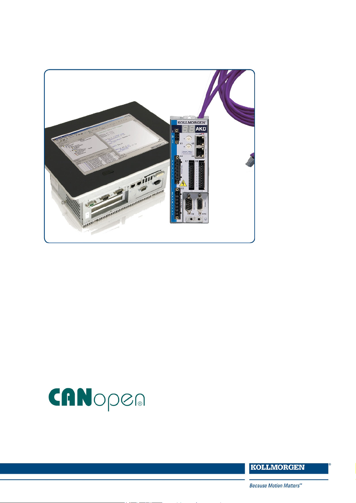
AKD™
CAN-BUS Communication
Edition: H, November 2012
Valid from firmware version 1.8
Part Number 903-200004-00
Original Documentation
Keep all manuals as a product component during the life span of the product.
Pass all manuals to future users and owners of the product.
Page 2

Record of Document Revisions
Revision Remarks
- ,11/2009 Beta launch version
-, 12/2009 Objects 2018&60FE added, Object dictionary, formatting updated
A, 04/2010 Termination connector "optional", several new objects, Object dictionary split
B, 07/2010 Part number added, several new objects, object dictionary expanded
C, 01/2011 HW Rev. C, new objects, object dictionary expanded
D, 04/2011 Object dictionary updated, baudrate setup
E, 10/2011
Cover layout & error table & object dictionary updated, objects 3474 & 3475 & 3496 & 6091
added
Touch Probe objects 60B8 to 60BD & 60D0 added, object 2071 & 2077 added, PVT inter-
F, 03/2012
polation added, 60C0 & 60C1 & 60C4 & 6041 bit 9 updated, object dictionary updated, error
codes updated, object 1011h added
G, 08/2012 Object dictionary updated, error codes updated
H, 11/2012 Object dictionary updated, error codes updated, new object 345A
Trademarks
l AKD is a registered trademark of Kollmorgen™ Corporation
l EnDat is a registered trademark of Dr. Johannes Heidenhain GmbH
l EtherCAT is a registered trademark and patented technology, licensed by Beckhoff Automation GmbH
l Ethernet/IP is a registered trademark of ODVA, Inc.
l Ethernet/IP Communication Stack: copyright (c) 2009, Rockwell Automation
l HIPERFACE is a registered trademark of Max Stegmann GmbH
l PROFINET is a registered trademark of PROFIBUS and PROFINET International (PI)
l SIMATIC is a registered trademark of SIEMENS AG
l Windows is a registered trademark of Microsoft Corporation
Current patents
l US Patent 5,162,798 (used in control card R/D)
l US Patent 5,646,496 (used in control card R/D and 1 Vp-p feedback interface)
l US Patent 6,118,241 (used in control card simple dynamic braking)
l US Patent 8,154,228 (Dynamic Braking For Electric Motors)
l US Patent 8,214,063 (Auto-tune of a Control System Based on Frequency Response)
Technical changes which improve the performance of the device may be made without prior notice!
Printed in the United States of America
This document is the intellectual property of Kollmorgen™. All rights reserved. No part of this work may be
reproduced in any form (by photocopying, microfilm or any other method) or stored, processed, copied or distributed by electronic means without the written permission of Kollmorgen™.
2 Kollmorgen™ | November 2012
Page 3

AKD CANopen | Table of Contents
1 Table of Contents
1 Table of Contents 3
2 General 9
2.1 About this Manual 10
2.2 Target Group 10
2.3 Symbols used 11
2.4 Abbreviations used 12
3 Safety 13
3.1 Safety Instructions 14
3.2 Use As Directed 14
3.3 Prohibited Use 14
4 Installation and Setup 15
4.1 Safety Instructions 16
4.2 CAN-Bus Interface (X12/X13) 17
4.2.1 CAN-Bus activation with AKD-CC models 18
4.2.2 Baudrate for CAN-Bus 19
4.2.3 Node Address for CAN-Bus 20
4.2.4 CAN-Bus Termination 20
4.2.5 CAN-Bus Cable 20
4.2.6 CAN-Bus Wiring 21
4.3 Guide to Setup 22
5 CANopen Basics 23
5.1 Basic Features implemented by CANopen 24
5.1.1 Setup and general functions: 24
5.1.2 Positioning functions: 24
5.1.3 Data transfer functions: 24
5.2 Transmission Rate and Procedure 24
5.3 Response to BUSOFF Communication Faults 25
5.4 Important Configuration Parameters 25
6 CANopen Communication Profile 26
6.1 General Description of CAN 27
6.2 Construction of the Communication Object Identifier 28
6.3 Definition of the Used Data Types 29
6.3.1 Basic data types 29
6.3.1.1 Unsigned Integer 29
6.3.1.2 Signed Integer 30
6.3.2 Mixed data types 30
6.3.3 Extended data types 31
6.3.3.1 Octet String 31
6.3.3.2 Visible String 31
6.4 Communication Objects 31
6.4.1 Network Management Objects (NMT) 32
6.4.2 Synchronization Object (SYNC) 32
6.4.3 Time-Stamp Object (TIME) 32
Kollmorgen™ | November 2012 3
Page 4

AKD CANopen | Table of Contents
6.4.4 Emergency Object (EMCY) 33
6.4.4.1 Application of the Emergency Object 33
6.4.4.2 Composition of the Emergency Object 33
6.4.5 Service Data Objects (SDO) 34
6.4.5.1 Composition of the Service Data Object 34
6.4.5.2 Initiate SDO Download Protocol 36
6.4.5.3 Download SDO Segment Protocol 36
6.4.5.4 Initiate SDO Upload Protocol 36
6.4.5.5 Upload SDO Segment Protocol 36
6.4.5.6 Abort SDO Protocol 36
6.4.6 Process Data Object (PDO) 37
6.4.6.1 Transmission modes 38
6.4.6.2 Trigger modes 38
6.4.7 Nodeguard 39
6.4.8 Heartbeat 40
7 CANopen Drive Profile 41
7.1 CANopen Emergency Messages and Error Codes 42
7.2 General Definitions 46
7.2.1 General objects 46
7.2.1.1 Object 1000h: Device Type (DS301) 46
7.2.1.2 Object 1001h: Error register (DS301) 47
7.2.1.3 Object 1002h: Manufacturer Status Register (DS301) 48
7.2.1.4 Object 1003h: Predefined Error Field (DS301) 49
7.2.1.5 Object 1005h: COB-ID of the SYNC Message (DS301) 50
7.2.1.6 Object 1006h: Communication Cycle Period (DS301) 50
7.2.1.7 Object 1008h: Manufacturer Device Name (DS301) 51
7.2.1.8 Object 1009h: Manufacturer Hardware Version 51
7.2.1.9 Object 100Ah: Manufacturer Software Version (DS301) 51
7.2.1.10 Object 100Ch: Guard Time (DS301)Response monitoring 52
7.2.1.11 Object 100Dh: Lifetime Factor (DS301) 52
7.2.1.12 Object 1010h: Store Parameters (DS301) 53
7.2.1.13 Object 1011h: Restore Default Parameters DS301 54
7.2.1.14 Object 1014h: COB-ID for Emergency Message (DS301) 55
7.2.1.15 Object 1016h: Consumer Heartbeat Time 55
7.2.1.16 Object 1017h: Producer Heartbeat Time 56
7.2.1.17 Object 1018h: Identity Object (DS301) 56
7.2.1.18 Object 1026h: OS Prompt 58
7.2.2 Manufacturer specific objects 59
7.2.2.1 Object 2014-2017h: 1st-4th Mask 1 to 4 for Transmit-PDO 59
7.2.2.2 Object 2018h: Firmware Version 60
7.2.2.3 Object 2026h: ASCII Channel 61
7.2.2.4 Object 20A0h: Latch position 1, positive edge 62
7.2.2.5 Object 20A1h: Latch position 1, negative edge 62
7.2.2.6 Object 20A2h: Latch position 2, positive edge 62
7.2.2.7 Object 20A3h: Latch position 2, negative edge 63
7.2.2.8 Object 20A4h: Latch Control Register 63
4 Kollmorgen™ | November 2012
Page 5

AKD CANopen | Table of Contents
7.2.2.9 Object 20A5h: Latch Status Register 64
7.2.2.10 Object 20A6h: Latch position 1, positive or negative edge 64
7.2.2.11 Object 20B8h: Reset of changed input information 65
7.2.2.12 Object 345Ah: Brake Control 66
7.2.2.13 Object 3474h: Parameters for digital inputs 68
7.2.2.14 Object 3475h: Parameters for digital outputs 69
7.2.2.15 Object 3496h: Fieldbus synchronization parameters 70
7.2.3 Profile specific objects 72
7.2.3.1 Object 60B8h: Touch probe function 72
7.2.3.2 Object 60B9h: Touch probe status 73
7.2.3.3 Object 60BAh: Touch probe 1 positive edge 74
7.2.3.4 Object 60BBh: Touch probe 1 negative edge 74
7.2.3.5 Object 60BCh: Touch probe 2 positive edge 74
7.2.3.6 Object 60BDh: Touch probe 2 negative edge 75
7.2.3.7 Object 60D0h: Touch probe source 75
7.2.3.8 Object 60FDh: Digital inputs (DS402) 76
7.2.3.9 Object 60FEh: Digital outputs (DS402) 77
7.2.3.10 Object 6502h: Supported drive modes (DS402) 78
7.3 PDO Configuration 79
7.3.1 Receive PDOs (RXPDO) 80
7.3.1.1 Objects 1400-1403h: 1st - 4th RXPDO communication parameter (DS301) 80
7.3.1.2 Objects 1600-1603h: 1st - 4th RXPDO mapping parameter (DS301) 81
7.3.1.3 Default RXPDO definition 82
7.3.2 Transmit PDOs (TXPDO) 83
7.3.2.1 Objects 1800-1803h: 1st - 4th TXPDO communication parameter (DS301) 83
7.3.2.2 Objects 1A00-1A03h: 1st - 4th TXPDO mapping parameter (DS301) 85
7.3.2.3 Default TXPDO definition 86
7.4 Device Control (dc) 87
7.4.1 Status Machine (DS402) 87
7.4.1.1 States of the Status Machine 88
7.4.1.2 Transitions of the status machine 89
7.4.2 Object Description 90
7.4.2.1 Object 6040h: Control word (DS402) 90
7.4.2.2 Object 6041h: Status word (DS402) 91
7.4.2.3 Object 6060h: Modes of Operation (DS402) 93
7.4.2.4 Object 6061h: Modes of Operation Display (DS402) 94
7.5 Factor Groups (fg) (DS402) 94
7.5.1 General Information 94
7.5.1.1 Factors 94
7.5.1.2 Relationship between Physical and Internal Units 94
7.5.2 Objects for velocity scaling 95
7.5.2.1 Object 204Ch: PV Scaling Factor 95
7.5.3 Objects for position calculation 96
7.5.3.1 Object 608Fh: Position encoder resolution (DS402) 96
7.5.3.2 Object 6091h: Gear Ratio (DS402) 97
7.5.3.3 Object 6092h: Feed constant (DS402) 98
Kollmorgen™ | November 2012 5
Page 6

AKD CANopen | Table of Contents
7.6 Profile Velocity Mode (pv) (DS402) 99
7.6.1 General Information 99
7.6.1.1 Objects that are defined in this section 99
7.6.1.2 Objects that are defined in other sections 99
7.6.2 Object description 99
7.6.2.1 Object 606Ch: Velocity actual value (DS402) 99
7.6.2.2 Object 60FFh: Target velocity (DS402) 100
7.7 Profile Torque Mode (tq) (DS402) 101
7.7.1 General Information 101
7.7.1.1 Objects that are defined in this section 101
7.7.1.2 Objects that are defined in other sections 101
7.7.2 Object description 101
7.7.2.1 Object 2071h: Target Current 101
7.7.2.2 Object 2077h: Current ActualValue 101
7.7.2.3 Object 6071h: Target torque (DS402) 102
7.7.2.4 Object 6073h: Max current (DS402) 102
7.7.2.5 Object 6077h: Torque actual value (DS402) 102
7.8 Position Control Function (pc) (DS402) 103
7.8.1 General Information 103
7.8.1.1 Objects that are defined in this section 103
7.8.1.2 Objects that are defined in other sections 103
7.8.2 Object Description 103
7.8.2.1 Object 6063h: position actual value* (DS402) 103
7.8.2.2 Object 6064h: position actual value (DS402) 104
7.8.2.3 Object 6065h: Following error window 104
7.8.2.4 Object 60F4h: Following error actual value (DS402) 104
7.9 Interpolated Position Mode (ip) (DS402) 105
7.9.1 General information 105
7.9.1.1 Objects defined in this section 105
7.9.1.2 Objects defined in other sections 105
7.9.2 Object description 105
7.9.2.1 Object 60C0h: Interpolation sub mode select 105
7.9.2.2 Object 60C1h: Interpolation data record 106
7.9.2.3 Object 60C2h: Interpolation time period 107
7.9.2.4 Object 60C4h: Interpolation data configuration 108
7.10 Homing Mode (hm) (DS402) 110
7.10.1 General information 110
7.10.1.1 Objects that are defined in this section 110
7.10.1.2 Objects that are defined in other sections 110
7.10.2 Object Description 110
7.10.2.1 Object 607Ch: Homing offset (DS402) 110
7.10.2.2 Object 6098h: Homing method (DS402) 110
7.10.2.3 Object 6099h: Homing speeds (DS402) 112
7.10.2.4 Object 609Ah: Homing acceleration (DS402) 112
7.10.2.5 Homing Mode Sequence 113
7.11 Profile Position Mode (DS402) 114
6 Kollmorgen™ | November 2012
Page 7

AKD CANopen | Table of Contents
7.11.1 General Information 114
7.11.1.1 Objects that are defined in this section 114
7.11.1.2 Objects that are defined in other sections 114
7.11.2 Object Description 115
7.11.2.1 Object 607Ah: Target position (DS402) 115
7.11.2.2 Object 607Dh: Software position limit (DS402) 115
7.11.2.3 Object 6081h: Profile velocity (DS402) 116
7.11.2.4 Object 6083h: Profile acceleration (DS402) 116
7.11.2.5 Object 6084h: Profile deceleration (DS402) 116
7.11.2.6 Functional Description 117
8 Appendix 119
8.1 Object Dictionary 119
8.1.1 Float Scaling 119
8.1.2 Communication SDOs 119
8.1.3 Manufacturer specific SDOs 122
8.1.4 Profile specific SDOs 136
8.2 Examples 138
8.2.1 Examples, setup 138
8.2.1.1 Basic testing of the connection to the AKD controls 138
8.2.1.2 Example: Operating the Status Machine 139
8.2.1.3 Example: Jog Mode via SDO 140
8.2.1.4 Example: Torque Mode via SDO 140
8.2.1.5 Example: Jog Mode via PDO 141
8.2.1.6 Example: Torque Mode via PDO 143
8.2.1.7 Example: Homing via SDO 144
8.2.1.8 Example: Using the Profile Position Mode 146
8.2.1.9 Example: ASCII Communication 149
8.2.1.10 Test for SYNC telegrams 150
8.2.2 Examples, special applications 151
8.2.2.1 Example: External Trajectory with Interpolated Position Mode 151
8.2.2.2 Example: PVT Interpolation 156
9 Index 159
Kollmorgen™ | November 2012 7
Page 8

AKD CANopen | Table of Contents
This page intentionally left blank.
8 Kollmorgen™ | November 2012
Page 9

AKD CANopen | 2 General
2 General
2.1 About this Manual 10
2.2 Target Group 10
2.3 Symbols used 11
2.4 Abbreviations used 12
Kollmorgen™ | November 2012 9
Page 10
AKD CANopen | 2 General
2.1 About this Manual
This manual, AKD CAN-Bus Communication, This manual describes the installation, setup, range of functions,
and software protocol for the CANopen AKD product series. All AKD CANopen drives have built-in CANopen
functionality; therefore an additional option card is not required.
A digital version of this manual (pdf format) is available on the DVD included with your drive. Manual updates can
be downloaded from the Kollmorgen™ website.
Related documents for the AKD series include:
l AKD Quick Start (also provided in hard copy). This guide provides instructions for initial drive setup and con-
nection to a network.
l AKD Installation Manual (also provided in hard copy for EU customers). This manual provides instructions for
installation and drive setup.
l AKD Users Manual. This manual describes how to use your drive in common applications. It also provides
tips for maximizing your system performance with the AKD.
l AKD Parameter and Command Reference Guide. This guide provides documentation for the parameters and
commands used to program the AKD.
l Accessories Manual. This manual provides documentation for accessories like cables and regen resistors
used with AKD. Regional versions of this manual exist.
Additional documentation:
l CAN Application (CAL) for Industrial Applications (publisher CiA e.V.)
l Draft Standards 301 (from Version 4.0), 402 (publisher CiA e.V.)
l CAN Specification Version 2.0 (publisher CiA e.V.)
l ISO 11898 ... Controller Area Network (CAN) for high-speed communication
2.2 Target Group
This manual addresses personnel with the following qualifications:
l Installation: only by electrically qualified personnel.
l Setup : only by qualified personnel with extensive knowledge of electrical engineering
and drive technology
l Programming: Software developers, project-planners
The qualified personnel must know and observe the following standards:
l ISO 12100, IEC 60364 and IEC 60664
l National accident prevention regulations
During operation there are deadly hazards, with the possibility of death,
severe injury or material damage. The operator must ensure that the safety
instructions in this manual are followed. The operator must ensure that all personnel responsible for working with the servo drive have read and understand
the manual.
10 Kollmorgen™ | November 2012
Page 11
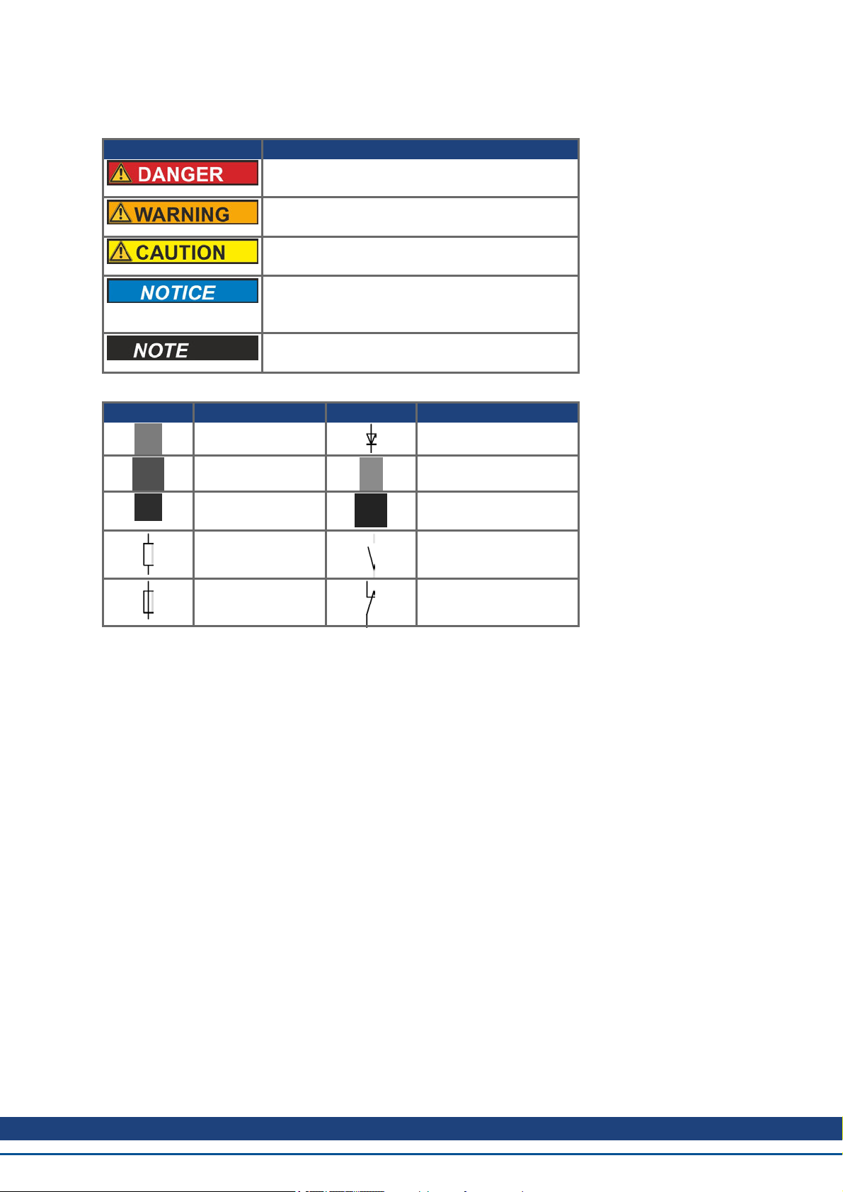
2.3 Symbols used
Warning Symbols
Symbol Indication
Indicates a hazardous situation which, if not
avoided, will result in death or serious injury.
Indicates a hazardous situation which, if not
avoided, could result in death or serious injury.
Indicates a hazardous situation which, if not
avoided, could result in minor or moderate injury.
This is not a safety symbol.
Indicates situations which, if not avoided, could
result in property damage.
This is not a safety symbol.
This symbol indicates important notes.
Drawing symbols
Symbol Description Symbol Description
Signal ground Diode
AKD CANopen | 2 General
Chassis ground Relays
Protective earth Relays switch off
delayed
Resistor Normal open contact
Fuse Normal closed contact
Kollmorgen™ | November 2012 11
Page 12

AKD CANopen | 2 General
2.4 Abbreviations used
Abbreviation Meaning
BTB/RTO Ready to operate (standby)
COB Communication Object
COB-ID Communication Object Identifier
EEPROM Electrically erasable/programmable memory
EMC Electromagnetic compatibility
EMCY Emergency Objects
ISO International Standardization Organization
km 1000 m
LED Light-emitting diode
LSB Low significant Byte (or Bit)
MSB Main significant Byte (or Bit)
MB Megabyte
NMT Network Management Objects
NSTOP Limit switch for negative (left) rotation
PC Personal Computer
PDO Process Data Object
PSTOP Limit switch for positive (right) rotation
RAM Volatile memory
ROD Incremental position encoder
RXPDO Receive PDO
SDO Service Data Object
SYNC Synchronization Objects
TXPDO Transmit PDO
12 Kollmorgen™ | November 2012
Page 13

AKD CANopen | 3 Safety
3 Safety
3.1 Safety Instructions 14
3.2 Use As Directed 14
3.3 Prohibited Use 14
Kollmorgen™ | November 2012 13
Page 14
AKD CANopen | 3 Safety
3.1 Safety Instructions
During operation there are deadly hazards, with the possibility of death,
severe injury or material damage. Do not open or touch the equipment during
operation. Keep all covers and cabinet doors closed during operation. Touching the equipment is allowed during installation and commissioning for properly qualified persons only.
Electronic equipment is basically not failure-proof. The user is responsible
for ensuring that, in the event of a failure of the drive, the drive is set to a
state that is safe for both machinery and personnel, for instance with the aid
of a mechanical brake.
Drives with drives and CANopen expansion cards are remote-controlled
machines. They can start to move at any time without previous warning. Take
appropriate measures to ensure that the operating and service personnel is
aware of this danger.
Implement appropriate protective measures to ensure that any unintended
start-up of the machines cannot result in dangerous situations for personnel
or machinery. Software limit-switches are not a substitute for the hardware
limit-switches in the machine.
l During operation, drives may have uncovered live components, depending
on their level of enclosure protection.
l Control and power connections may be live, even though the motor is not
rotating.
l Drives may have hot surfaces during operation. Heat sink can reach tem-
peratures above 80°C.
Install the drive as described in the Installation Manual. The wiring for the
analog setpoint input and the positioning interface, as shown in the wiring
diagram in the Installation Manual, is not required. Never break any of the
electrical connections to the drive while it is live. This action can result in
destruction of the electronics
3.2 Use As Directed
Drives are components that are built into electrical plants or machines and can only be operated as integral components of these plants or machines. The manufacturer of the machine used with a drive must generate a risk
assessment for the machine and take appropriate measures to ensure that unforeseen movements cannot cause
personnel injury or property damage.
Please observe the chapters "Use as directed” and "Prohibited use" in the AKD Installation Manual.
The CANopen interface serves only for the connection of the AKD to a master via the CAN bus.
3.3 Prohibited Use
Other use than that described in chapter “Use as directed” is not intended and can lead to personnel injuries and
equipment damage. The drive may not be used with a machine that does not comply with appropriate national
directives or standards. The use of the drive in the following environments is also prohibited:
l potentially explosive areas
l environments with corrosive and/or electrically conductive acids, alkaline solutions, oils, vapors, dusts
l ships or offshore applications
14 Kollmorgen™ | November 2012
Page 15

AKD CANopen | 4 Installation and Setup
4 Installation and Setup
4.1 Safety Instructions 16
4.2 CAN-Bus Interface (X12/X13) 17
4.3 Guide to Setup 22
Kollmorgen™ | November 2012 15
Page 16
AKD CANopen | 4 Installation and Setup
4.1 Safety Instructions
Never undo any electrical connections to the drive while it is live. There is a danger of
electrical arcing with damage to contacts and serious personal injury. Wait at least
seven minutes after disconnecting the drive from the main supply power before touching potentially live sections of the equipment (e.g. contacts) or undoing any connections.
Capacitors can still have dangerous voltages present up to 7 minutes after switching
off the supply power. To be sure, measure the voltage in the DC Bus link and wait
until it has fallen below 40 V.
Control and power connections can still be live, even if the motor is not rotating.
Electronic equipment is basically not failure-proof. The user is responsible for ensuring that, in the event of a failure of the drive, the drive is set to a state that is safe for
both machinery and personnel, for instance with the aid of a mechanical brake.
Drives with drives and CANopen are remote-controlled machines. They can start to
move at any time without previous warning. Take appropriate measures to ensure
that the operating and service personnel is aware of this danger.
Implement appropriate protective measures to ensure that any unintended start-up of
the machines cannot result in dangerous situations for personnel or machinery. Software limit-switches are not a substitute for the hardware limit-switches in the
machine.
Install the drive as described in the Installation Manual. The wiring for the analog set-
point input and the positioning interface, as shown in the wiring diagram in the Instal-
lation Manual, is not required. Never break any of the electrical connections to the
drive while it is live. This action can result in destruction of the electronics.
The drive's status must be monitored by the PLC to acknowledge critical situations.
Wire the FAULT contact in series into the emergency stop circuit of the installation.
The emergency stop circuit must operate the supply contactor.
It is permissible to use the setup software to alter the settings of the drive. Any other
alterations will invalidate the warranty.
Because of the internal representation of the position-control parameters, the position
controller can only be operated if the final limit speed of the drive does not exceed:
rotary
at sinusoidal² commutation: 7500 rpm
at trapezoidal commutation: 12000 rpm.
linear
at sinusoidal² commutation: 4 m/s
at trapezoidal commutation: 6.25 m/s
All the data on resolution, step size, positioning accuracy etc. refer to calculatory
values. Non-linearities in the mechanism (backlash, flexing, etc.) are not taken into
account. If the final limit speed of the motor must be altered, then all the parameters
that were previously entered for position control and motion blocks must be adapted.
16 Kollmorgen™ | November 2012
Page 17
AKD CANopen | 4 Installation and Setup
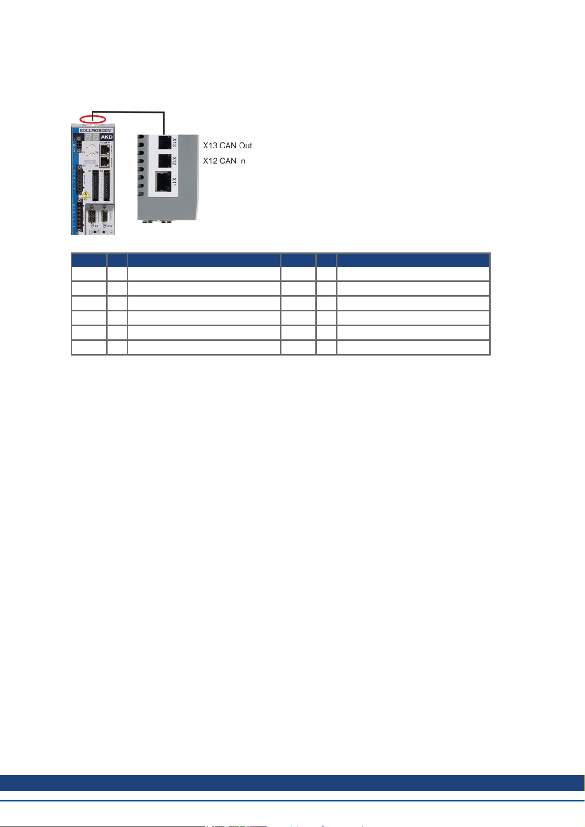
4.2 CAN-Bus Interface (X12/X13)
Two 6-pin RJ-12 connectors X12/X13 are used for CAN-Bus connection.
Conn. Pin Signal Conn. Pin Signal
X12 1 Internal Termination Resistor X13 1 Internal Termination Resistor
X12 2 CAN Shield X13 2 CAN Shield
X12 3 CANH in X13 3 CANH out
X12 4 CANL in X13 4 CANL out
X12 5 GND X13 5 GND
X12 6 Internal Termination Resistor X13 6 Internal Termination Resistor
Kollmorgen™ | November 2012 17
Page 18
AKD CANopen | 4 Installation and Setup
4.2.1 CAN-Bus activation with AKD-CC models
AKD-CC drive models are Drives, which support EtherCAT and CAN fieldbus types within one common software. These CC drive models allow selecting a fieldbus support by setting the DRV.TYPE parameter to a certain
value. CC drive models are delivered with EtherCAT set active.
To activate CANopen, the DRV.TYPE parameter must be changed
1. by software: connect the PC to the AKD and change the parameter DRV.TYPE in the WorkBench terminal
screen (see DRV.TYPE parameter documentation) or
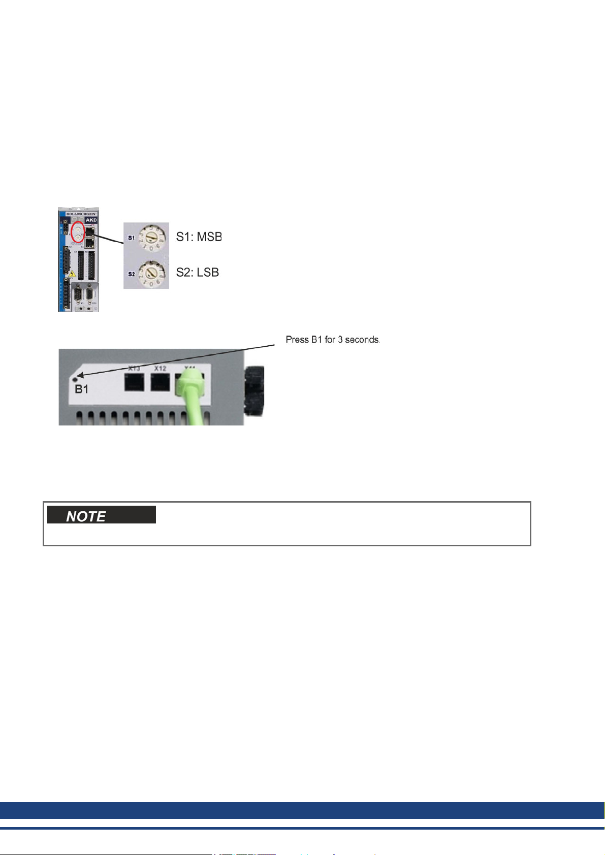
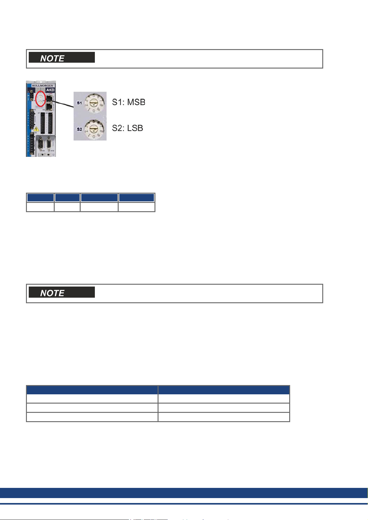
2. by hardware: with the rotary switches S1 & S2 at the front and the button B1 on the top side of the Drive.
The following steps are needed for changing the fieldbus type from EtherCAT to CAN with the rotary switches.
1. Set the rotary switches on the front side of the AKD to the value of 89.
Set S1 to 8 and S2 to 9
2. Press the button B1 for about 3 seconds (starts DRV.NVSAVE).
The seven segment display shows Cn during the process of changing DRV.TYPE to CAN.
Do not switch off the 24[V] power supply while the seven segment shows Cn!
3. Wait until the seven segment display goes back to the original state, no the drive is prepared for CAN.
4. Power cycle the drive by switching the 24 V power supply off and then on again.
The seven segment display shows Er (Error) in case that the DRV.TYPE
instruction failed. In this case please power cycle the drive and contact the
Kollmorgen™ customer support for further help.
18 Kollmorgen™ | November 2012
Page 19
AKD CANopen | 4 Installation and Setup
4.2.2 Baudrate for CAN-Bus
The user can decide to use a fixed baud rate or an auto baud detection algorithm for the startup behaviour of the
drive. The transmission rate can be set via the parameter FBUS.PARAM01. The parameter FBUS.PARAM01
can either be set via WorkBench or via a special mechanism with the rotary switches in the AKD front.
Baudrate
[kBit/s] FBUS.PARAM01
Upper rotary
switch S1
Lower rotary
switch S2
auto 0 9 0
125 125 9 1
250 250 9 2
500 500 9 3
1000 1000 9 4
In case of a fix baud rate, the drive sends the boot up message with the baud rate saved in the drive's non volatile
memory after a power cycle. In case of auto baud detection, the drive listens for a valid CAN frame on the bus.
When a valid frame is received, the drive sends the boot up message with the measured bit time. Afterwards the
baud rate can either be stored to non volatile memory via object 1010 sub 1, or the auto baud mechanism is used
always.
For reliable auto baud detection, it is recommended to use suitable cabling
of the CAN-Bus (two terminators, GND connection etc.). Spikes or other
noise effects on the CAN-Bus can disturb the measurement. The drive needs
to be disabled, if auto baud is in use.
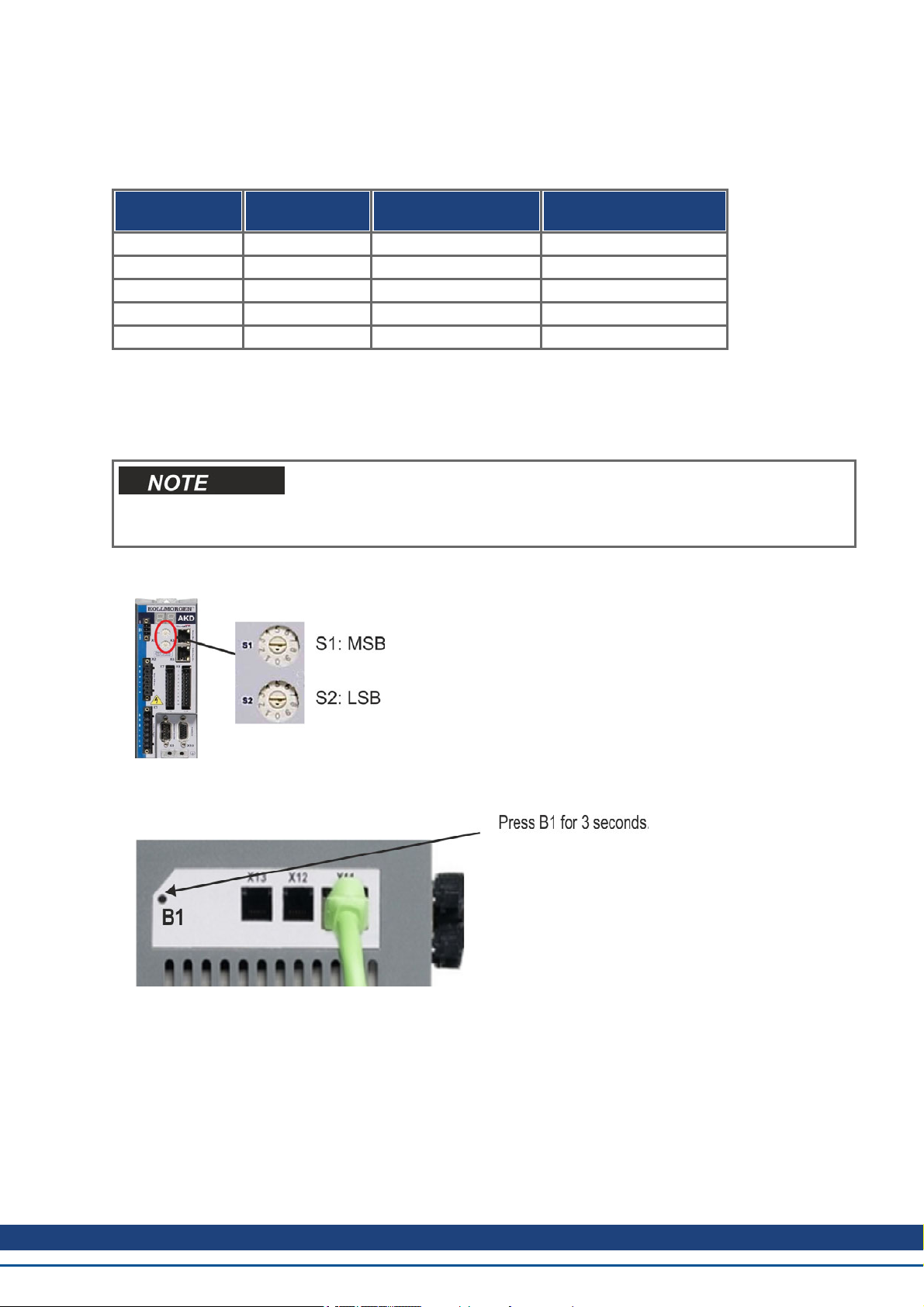
For setting the baudrate with rotary switches, follow the procedure below (drive state disabled):
1. Disable the drive. Set the rotary switches to one of the addresses 90 to 94 (see above table).
Set S1 to 9 and S2 to either 0 or 4
2. Push the button B1 on the AKDfor at least 3 seconds until the rotary switch setting is displayed on the AKDdisplay.
3. When the display blinks with the set rotary switch setting stop pushing B1 and wait until the blinking stops.
During that time the parameter FBUS.PARAM01 is set to the new value and all parameters are stored to the
non volatile memory. The new setting will be taken with the next power-up of the drive.
If an error occurred, the following error messages will flash 5 times:
l E1 - Drive is enabled
l E2 - Non-volatile storage of the new setting failed
l E3 - Invalid rotary switch selection
Kollmorgen™ | November 2012 19
Page 20
AKD CANopen | 4 Installation and Setup
4.2.3 Node Address for CAN-Bus
After changing the node address, you must turn off the 24 V auxiliary supply
for the drive and then turn it on again.
During setup, use the rotary switches on the AKD front panel to preset the station address for communication.
The rotary switches on the front of the AKD (S1&S2) correspond to the CAN node address.
The S1&S2 switches also correspond to the IP address setting of the drive. Both CAN and IP network address
schemes have to be configured to account for this dependence if both TCP/IP and CAN networks are running at
the same time in an application. Example:
S1 (MSB) S2 (LSB) CAN address IP address
4 5 45 192.168.0.45
The IP address setting can be decoupled from the Rotary switches using settings in the drive. Use Settings ->
Fieldbus-> TCP/IP to adjust these settings.
4.2.4 CAN-Bus Termination
The last bus device on both ends of the CAN-Bus system must have termination resistors. The AKD has built-in
132 ohms resistors that can be activated by connecting pins 1 and 6. An optional termination plug is available for
AKD (P-AKD-CAN-TERM). The optional termination plug is an RJ-12 connector with an enclosed wire jumper
between pins 1&6. A plug should be inserted into the X13 connector of the last drive in the CAN network.
Remove the termination connector if the AKD is not the last CAN-Bus device
and use X13 for connecting the next CAN node.
4.2.5 CAN-Bus Cable
To meet ISO 11898, a bus cable with a characteristic impedance of 120 ohms should be used. The maximum
usable cable length for reliable communication decreases with increasing transmission speed. As a guide, you
can use the following values which Kollmorgen™ has measured; however, these values are not assured limits:
l Characteristic impedance: 100–120 ohms
l Cable capacitance max.: 60 nF/km
l Lead loop resistance: 159.8 ohms/km
Cable length, depending on the transmission rate:
Transmission Rate (kBaud) Maximum Cable Length (m)
1,000 10
500 70
250 115
Lower cable capacitance (max. 30 nF/km) and lower lead resistance (loop resistance, 115 ohms/1000m) make it
possible to achieve greater distances.
(Characteristic impedance 150 ± 5 ohms requires terminating resistor 150 ± 5 ohms).
20 Kollmorgen™ | November 2012
Page 21
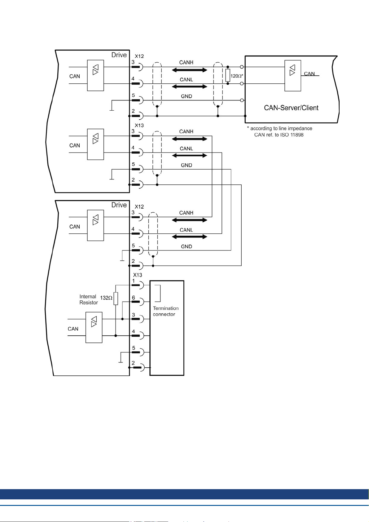
4.2.6 CAN-Bus Wiring
AKD CANopen | 4 Installation and Setup
Kollmorgen™ | November 2012 21
Page 22

AKD CANopen | 4 Installation and Setup
4.3 Guide to Setup
Only professional personnel with extensive knowledge of control and drive
technology are allowed to setup the drive.
Make sure that any unintended movement of the drive cannot endanger
machinery or personnel.
1. Check assembly/installation. Check that all the safety instructions in the product manual for the drive and
this manual have been observed and implemented. Check the setting for the station address and baud rate.
2. Connect PC,start WorkBench. Use the setup software WorkBench to set the parameters for the drive.
3. Setup basic functions. Start up the basic functions of the drive and optimize the current, speed and position
controllers. This section of the setup is described in the in the online help of the setup software.
4. Save parameters. When the parameters have been optimized, save them in the drive.
5. Start up communication. The altered parameters will only become effective after a reboot (switch off 24V and
switch on again). Adjust the transmission rate of the AKD to match the master.
6. Test communication. Check for the bootup-message, when you switch on the drive. Do an SDO read access
on index 0x1000 subindex 0 (DeviceType).
7. Setup position controller. Setup the position controller, as described in the WorkBench online help.
22 Kollmorgen™ | November 2012
Page 23

AKD CANopen | 5 CANopen Basics
5 CANopen Basics
5.1 Basic Features implemented by CANopen 24
5.2 Transmission Rate and Procedure 24
5.3 Response to BUSOFF Communication Faults 25
5.4 Important Configuration Parameters 25
Kollmorgen™ | November 2012 23
Page 24

AKD CANopen | 5 CANopen Basics
5.1 Basic Features implemented by CANopen
It is assumed that the basic operating functions of the communication profile are known and available as reference documentation. When working with the position controller that is integrated in AKD, the following functions are available:
5.1.1 Setup and general functions:
l Homing, set reference point
l Provision of a digital setpoint for speed and torque control
l Support of the following modes of the CANopen Profile DS402:
l Profile position mode
l Homing mode
l Profile torque mode
l Interpolated position mode
l Profile velocity mode
l Cyclic synchronous position mode
5.1.2 Positioning functions:
l Execution of a motion task from the motion block memory of the drive
l Execution of a direct motion task
l Absolute trajectory, ip-Mode or csp-Mode
5.1.3 Data transfer functions:
l Transmit a motion task to the drive's motion block memory. A motion task consists of these elements:
l Position setpoint (absolute task) or path setpoint (relative task)
l Speed setpoint
l Acceleration time, braking time
l Type of motion task (absolute/relative)
l Number of a following task (with or without pause)
l Read a motion task from the motion block memory of the drive
l Read actual values
l Read the error register (Emergency error codes)
l Read the status register
l Read/write control parameters
5.2 Transmission Rate and Procedure
l Bus connection and bus medium: CAN-standard ISO 11898 (CAN high-speed)
l Transmission rate: max. 1Mbit/s
l Possible settings for the drive: 125 (default), 250, 500 and 1000 kbit/s
l The baudrate is set with the AKD - parameter FBUS.PARAM01. It gets effective by saving this parameter to
NVRAM and re-starting the drive.
24 Kollmorgen™ | November 2012
Page 25

AKD CANopen | 5 CANopen Basics
5.3 Response to BUSOFF Communication Faults
The communication fault BUSOFF is directly monitored and signaled by Level 2 (CAN controller). This message
may have various causes. A few examples:
l Telegrams are transmitted, although there is no other CAN node connected
l CAN nodes have different transmission rates
l The bus cable is faulty
l Faulty cable termination causes reflections on the cable.
A BUSOFF is only signaled by the AKD, if another CAN node is connected and at least one object was successfully transmitted to start off with. The BUSOFF condition is signaled by the error message 702. If the output
stage is enabled at the moment when this fault occurs, the output stage is disabled.
5.4 Important Configuration Parameters
FBUS.PARAM01 see "Transmission Rate and Procedure" on p.24
FBUS.PARAM02 0 - no PLL used for synchronization
1 - PLL used for synchronized modes, IP (7), CSP (8), generates a warning n125, when PLL
is unlocked
FBUS.PARAM04 0 - arrival of SYNC-messages in cyclic-synchronized application is not supervised
1 - arrival of SYNC-messages in cyclic-synchronized application is supervised (after 3 missing SYNC-telegrams the fault F125 is generated)
FBUS.PARAM05 description for bits 0 to 3 as in AKD - command reference
Bit 0
1: Faults can only be reset using DS402 control word bit 7.
0 = 0: The reset can also be done via telnet or digital input and the DS402 state machine
reflects this condition.
Bit 1
1: The state of the hardware enable does not change the state machine state Operation Enable.
0: If the state Operation Enable or Switched on is active it falls back to the state switched On
Disabled, if the Hardware enable goes to 0.
Bit 2
1: Workbench/Telnet can not software enable the drive, when CANopen/EtherCAT are Operational.
0: Workbench/Telnet can software enable the drive.
Bit 3
1: DS402-state machine is not influenced, if the software-enable is taken away via Telnet.
0: DS402-state machine is influenced, if the software-enable is taken away via Telnet.
Bit 4
1: Scaling is done via special DS402 - objects (independent on units)
0: Scaling for position, velocity and acceleration objects is done via UNIT parameters
Bit 5 used in EtherCAT, reserved for CAN
Bit 6
1: Bit 0 of parameter MT.CNTL (object 35D9 sub 0) can be accesse
0: Bit 0 of parameter MT.CNTL (object 35D9 sub 0) is exclusively used for DS402 controlwordd
Kollmorgen™ | November 2012 25
Page 26

AKD CANopen | 6 CANopen Communication Profile
6 CANopen Communication Profile
6.1 General Description of CAN 27
6.2 Construction of the Communication Object Identifier 28
6.3 Definition of the Used Data Types 29
6.4 Communication Objects 31
26 Kollmorgen™ | November 2012
Page 27

AKD CANopen | 6 CANopen Communication Profile
6.1 General Description of CAN
This chapter describes the basic services and communication objects of the CANopen communication profile
DS 301, which are used in the AKD.
It is assumed that the basic operating functions of the communication profile
are known, and available as reference documentation.
The transmission method that is used here is defined in ISO 11898 (Controller Area Network CAN for high-speed
communication).
The Layer-1/2 protocol (Physical Layer/Data Link Layer) that is implemented in all CAN modules provides,
amongst other things, the requirements for data.
Data transport or data request is made by means of a data telegram (Data Frame) with up to 8 bytes of user data,
or by a data request telegram (Remote Frame).
Communication objects (COBs) are labeled by an 11-bit Identifier (ID) that also determines the priority of objects.
A Layer-7 protocol (Application Layer) was developed, to decouple the application from the communication. The
service elements that are provided by the Application Layer make it possible to implement an application that is
spread across the network. These service elements are described in the CAN Application Layer (CAL) for Industrial Applications.
The communication profile CANopen and the drive profile are mounted on the CAL.
The basic structure of a communication object is shown in the following diagram:
S
COB-ID R
O
M
SOM Start of message
COB-ID Communication Object Identifier (11-bit)
RTR Remote Transmission Request
CTRL Control Field (e.g. Data Length Code)
Data Segment 0 to 8byte (Data-COB)
CRC Cyclic Redundancy Check
ACK Acknowledge slot
EOM End of message
CTRL Data Segment CRC A
T
R
0byte (Remote-COB)
EOM
C
K
Kollmorgen™ | November 2012 27
Page 28
AKD CANopen | 6 CANopen Communication Profile
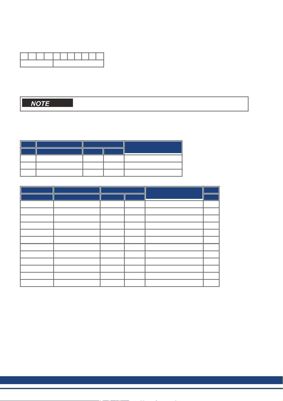
6.2 Construction of the Communication Object Identifier
The following diagram shows the layout of the COB Identifier (COB-ID). The Function Code defines the interpretation and priority of the particular object.
10 9 8 7 6 5 4 3 2 1 0
Function-Code Module-ID
Bit 0 .. 6
Module ID (drive's CAN-bus address, range 1 to 127; is set up in WorkBench or the drive,)
Bit 7 to 10
Function Code (number of the communication object that is defined in the server)
If an invalid station number (=0) is set, then the module will be set internally
to 1.
The following tables show the default values for the COB Identifier after switching on the drive. The objects,
which are provided with an index (Communication Parameters at Index), can have a new ID assigned after the
initialization phase. The indices in brackets are optional.
Predefined broadcast objects (send to all nodes):
Object Function code (binary) Resulting COB-IDs Communication parameters
Dec. Hex.
NMT 0000 0 0 —
SYNC 0001 128 80 (1005)
TIME 0010 256 100 not supported
at index
Predefined Peer-to-Peer objects (node sends to node):
Object Function code (binary) Resulting COB-IDs Communication parameters
Dec. Hex.
EMERGENCY 0001 129..255 81..FF — high
TPDO 1 0011 385..511 181..1FF 1800
RPDO 1 0100 513..639 201..27F 1400
TPDO 2 0101 641..767 281..2FF 1801
RPDO 2 0110 769..895 301..37F 1401
TPDO 3 0110 897..1023 381..3FF 1802
RPDO 3 1000 1025..1151 401..47F 1402
TPDO 4 1001 1153..1279 481..4FF 1803
RPDO 4 1010 1281..1407 501..57F 1403
SDO (tx*) 1011 1409..1535 581..5FF
SDO (rx*) 1100 1537..1663 601..67F
Nodeguard 1110 1793..1919 701..77F (100E) low
*tx = direction of transmission: AKD => Master
rx = direction of transmission: Master => AKD
at index
Priority
28 Kollmorgen™ | November 2012
Page 29
AKD CANopen | 6 CANopen Communication Profile
6.3 Definition of the Used Data Types
This chapter defines the data types that are used. Each data type can be described by bit- sequences. These bitsequences are grouped into "Octets” (bytes). The so-called "Little – Endian” format (a.k.a. Intel format) is used
for numerical data types (see also: DS301 Application Layer "General Description of Data Types and Encoding
Rules”).
6.3.1 Basic data types
6.3.1.1 Unsigned Integer
Data in the basic data type UNSIGNEDn define exclusively positive integers.
The value range is from 0 to 2n-1. The bit sequence b = b0to b
UNSIGNEDn(b) = b
n-1
n-1
2
+ to + b121+ b02
0
Example: the value 266 = 10Ah is transmitted in the data type UNSIGNED16, in the form of two octets (1stoctet
= 0Ah, 2ndoctet = 01h).
Transmission syntax for the data type UNSIGNEDn
Octet number 1. 2. 3. 4.
UNSIGNED8 b7to b
UNSIGNED16 b7to b
UNSIGNED24 b7to b
UNSIGNED32 b7to b
UNSIGNED40 b7to b
UNSIGNED48 b7to b
UNSIGNED56 b7to b
UNSIGNED64 b7to b
0
0
0
0
0
0
0
0
b15to b
b15to b
b15to b
b15to b
b15to b
b15to b
b15to b
8
8
8
8
8
8
8
b23to b
b23to b
b23to b
b23to b
b23to b
b23to b
defines the value
n-1
16
16
16
16
16
16
b31to b
b31to b
b31to b
b31to b
b31to b
24
24
24
24
24
Octet number 5. 6. 7. 8.
UNSIGNED8
UNSIGNED16
UNSIGNED24
UNSIGNED32
UNSIGNED40 b39to b
UNSIGNED48 b39to b
UNSIGNED56 b39to b
UNSIGNED64 b39to b
32
32
32
32
b47to b
b47to b
b47to b
40
40
40
b55to b
b55to b
48
48
b63to b
56
Kollmorgen™ | November 2012 29
Page 30

AKD CANopen | 6 CANopen Communication Profile
6.3.1.2 Signed Integer
Data in the basic data type INTEGERn define both positive and negative integers.
The value range is from-2
INTEGERn(b) = b
n-2
n-2
2
n-1
+ to + b121+ b020with b
-1 to 2
n-1
-1. The bit sequence b = b0to b
= 0
n-1
defines the value
n-1
Negative numbers are represented as 2’s complement, which means:
INTEGERn(b) = - INTEGERn(b) - 1 with b
n-1
= 1
Example: the value -266 = FEF6h is transmitted in the data type INTEGER16, in the form of two octets (1stoctet
= F6h, 2ndoctet = FEh).
Transmission syntax for the data type INTEGERn
Octet number 1. 2. 3. 4.
INTEGER8 b7to b
INTEGER16 b7to b
INTEGER24 b7to b
INTEGER32 b7to b
INTEGER40 b7to b
INTEGER48 b7to b
INTEGER56 b7to b
INTEGER64 b7to b
0
0
0
0
0
0
0
0
b15to b
b15to b
b15to b
b15to b
b15to b
b15to b
b15to b
8
8
8
8
8
8
8
b23to b
b23to b
b23to b
b23to b
b23to b
b23to b
16
16
16
16
16
16
b31to b
b31to b
b31to b
b31to b
b31to b
24
24
24
24
24
Octet number 5. 6. 7. 8.
INTEGER8
INTEGER16
INTEGER24
INTEGER32
INTEGER40 b39to b
INTEGER48 b39to b
INTEGER56 b39to b
INTEGER64 b39to b
32
32
32
32
b47to b
b47to b
b47to b
40
40
40
b55to b
b55to b
48
48
b63to b
56
6.3.2 Mixed data types
Mixed data types combine basic data types (INTEGERn, UNSIGNEDn, REAL). Two types of mixed data are distinguished:
l STRUCT: This data type is composed of elements with different data types.
l ARRAY: This data type is composed of elements of the same data type.
30 Kollmorgen™ | November 2012
Page 31

AKD CANopen | 6 CANopen Communication Profile
6.3.3 Extended data types
Extended data types are derived from basic data types and mixed data types. The types of extended data that
are supported are defined below.
6.3.3.1 Octet String
The data type OCTET_STRING is defined with the data type ARRAY. Length is the length of the octet string.
ARRAY[length] OF UNSIGNED8 OCTET_STRINGlength
6.3.3.2 Visible String
The data type VISIBLE_STRING can be defined with the data type UNSIGNED8 or the data type ARRAY. Permissible values are 00h and the range from 20h to 7Eh. The data are interpreted as 7 bit ASCII code (as per ISO
646-1973(E)). Length is the length of the visible string.
UNSIGNED8 VISIBLE_CHAR
ARRAY[length] OF VISIBLE_CHAR VISIBLE_STRINGlength
6.4 Communication Objects
Communication objects are described with the help of service elements and protocols. Two basic types of service elements are used.
l Unconfirmed services PDO
l Confirmed services SDO
All services require faultless operation of the Data Link and Physical Layer.
AKD supports communication objects that are described in detail in the following sections:
l Network Management Objects (NMT)
l Synchronization Object (SYNC)
l Emergency Object (EMCY)
l Process Data Object (PDO)
l Service Data Object (SDO)
l Nodeguard/Heartbeat
Kollmorgen™ | November 2012 31
Page 32

AKD CANopen | 6 CANopen Communication Profile
6.4.1 Network Management Objects (NMT)
The followind diagram describes the NMT telegram:
The drive supports the following network management functions:
cs = 129, reset node:
Causes a cold-start of the drive. This deletes all parameters saved in the RAM and loads the values stored in the
EEPROM.
cs = 130, reset communication node:
Causes a stop of PDO-communication, gives a new bootup-message
cs = 1, start remote node:
Starts the CAN node. I.e. the PDOs of the drive are enabled for operation. From this moment, transmit-PDOs will
be transmitted under event-control, and cyclical process data operation can commence.
cs = 2, stop remote node:
Stops the CAN node, I.e. the drive no longer responds to any received PDOs or transmits any PDOs.
6.4.2 Synchronization Object (SYNC)
The SYNC object usually is used as a periodic Broadcast Object and provides the basic clock for the bus. SYNC
has a high priority, to ensure constant time intervals. The usage of this protocol is explained in the appendix from
page . You can use the SYNC object to start motion task of several axes simultaneously for example.
6.4.3 Time-Stamp Object (TIME)
This communication object is not supported by the AKD.
32 Kollmorgen™ | November 2012
Page 33

AKD CANopen | 6 CANopen Communication Profile
6.4.4 Emergency Object (EMCY)
EMCY is event-triggered and generated by an internal fault/error situation. This object is transmitted afresh for
every error. Since the error codes are device-dependent, they are described in the Chapter ""CANopen Emer-
gency Messages and Error Codes" (=> p. 42)". The last 10 Emergency error codes can be read via object 1003.
6.4.4.1 Application of the Emergency Object
The reaction in the event of an error or fault depends on the error class and is therefore variable. For this reason,
the reaction is described with the aid of an error status machine. The error conditions error- free and error
occurred are distinguished. The following transitions are defined:
Transition 0: After initialization, the error-free status is taken up if no errors are detected.
No error signal is generated in this condition.
Transition1: The AKD detects an internal error and indicates this in the first three bytes
of the emergency telegram (error code in Bytes 0,1 and error register in Byte 2).
Transition2: One error has been reset, but not all. The EMCY telegram contains error code 0000
and the error register indicates the remaining errors that are present. The manufacture-specific area is set to
zero.
Transition3: A new error has occurred. The AKD remains in the error status and transmits an EMCY. Object
with the corresponding error code. The new error code is entered into bytes 0 and 1.
Transition4: All errors have been reset. The EMCY telegram contains the error code 0000,
The error register does not indicate any other errors. The manufacture-specific area is set to zero.
6.4.4.2 Composition of the Emergency Object
The Emergency Object is composed of 8 bytes, divided as follows:
Byte 0 1 2 3 4 5 6 7
Content Emergency error code Error register (object 1001 Category Reserved
If an Emergency Object is generated, the error condition is then signaled to the status machine (error free/error
occurred) by the generation of a second Emergency Object. Only the first four bytes are relevant in this case
(Emergency Error code , Error register, Category). Byte 0/1 contains the Emergency Error Code (0000) and Byte
2 indicates if a possible further error is present. If the error register contains 00, the error status is error-free. Byte
3 contains the category. The interpretations of the error numbers (error code) and the error categories are
described in the section Emergency Messages. The error register is defined through object 1001. Error register´.
Kollmorgen™ | November 2012 33
Page 34

AKD CANopen | 6 CANopen Communication Profile
6.4.5 Service Data Objects (SDO)
SDOs are used to implement access to the Object Dictionary. The SDOs are required for parametrerization and
for status polling. Access to an individual object is made with a multiplexer via the Index and Subindex of the
Object Dictionary. The following communication protocols are supported by AKD:
l Initiate SDO Download Protocol
l Download SDO Segment Protocol
l Initiate SDO Upload Protocol
l Upload SDO Segment Protocol
l Abort SDO Transfer Protocol
The definitions of the individual communication services and protocols can be found in DS301.
Examples of the usage of SDOs can be found in the appendix from page .
Since a SDO is a confirmed service, the system must always wait for the SDO
response telegram before it is allowed to transmit a new telegram.
6.4.5.1 Composition of the Service Data Object
An SDO consists of the following components:
Byte 1 2 3 4 5 6 7 8
Content R/W Index Subindex Data
1. The control byte (Byte 1):
The control byte determines whether the SDO should write or read the content of the entry in the Object Dictionary. A description of the complete Object Dictionary for AKD=> p. 119. Data exchange with the AKD is governed by the CMS multiplexed domain protocols standard, as described in the CAN standard DS 202.
To read data, the control byte must be written in the manner shown below:
Bit 7 6 5 4 3 2 1 0
Content ccs=2 X X X X X
ccs => client command specifier (ccs = 2 => initiate upload request)
X => free data
So a value of 0100 0000 (binary) or 40h must be transmitted in the control byte.
The drive sends back a corresponding response byte:
Bit 7 6 5 4 3 2 1 0
Content scs=2 X n e s
scs =>server command specifier (scs = 2 => initiate upload response)
n =>only valid for e = s = 1, if this is so, n contains the number of bytes that do not contain data
X =>free data
If reading is successfull, the response byte always has set the bits 0 and 1 (e = s = 1).
Encoded byte length in the SDO response:
0x43 - 4 bytes
0x47 - 3 bytes
0x4B - 2 bytes
0x4F - 1 byte.
If an error occurs, scs is set to 4, the response byte is 0x80 and the error information is in
the four byte data field. The decoding of the error => p. 42
34 Kollmorgen™ | November 2012
Page 35

AKD CANopen | 6 CANopen Communication Profile
To write data, the control byte must be written in the manner shown below:
Client Initiate Domain Download Server
Byte 1 2 3 4 5 6 7 8
request 7 6 5 4 3 2 1 0 indication
=> ccs=1 X n e s m d =>
=> => => => => =>=> => =>=> => =>=> => =>=> => =>=> => =>
n,e and s are defined like in the reading case, m: index + Subindex, d: 4 bytes data field
The data length of an object can be taken from the object dictionary in the appendix.
The control byte should be:
0x23 for a 4-byte access
0x27 for a 3-byte access
0x2B for a 2-byte access
0x2F for a 1-byte access
Client <= <= <= <= <= <=<= <= <=<= <= <=<= <= <=<= <= <=<= <= <= Server
Byte 1 2 3 4 5 6 7 8
confirm 7 6 5 4 3 2 1 0 response
<= scs=3 X min reserved <=
2. Index (Bytes 2 and 3):
The Index is the main entry in the Object Dictionary, and divides the parameters into groups.
(Example: Index 1018h is the Identity Object). As for all CAN data, the Index is stored with the bytes in reverse
order.
For example: Index 6040h means Byte 2 = 40h, Byte 3 = 60h)
3. Subindex (Byte 4):
The Subindex divides the parameters within a group of parameters.
4. Data field (Bytes 5 to 8):
These components are used for the exchange of user data. In read-request telegrams to the AKD they are set to
0. They have no content in a write confirmation from the AKD if the transfer was successful, but if the write operation was faulty they contain an error => p. 42.
Kollmorgen™ | November 2012 35
Page 36

AKD CANopen | 6 CANopen Communication Profile
6.4.5.2 Initiate SDO Download Protocol
The Initiate SDO Download protocol is used for write access to objects with up to 4 bytes of user data (expedited
transfer) or to initiate a segment transfer (normal transfer).
6.4.5.3 Download SDO Segment Protocol
The Download SDO Segment protocol is used for write access to objects with more than 4 bytes of user data
(normal transfer).
6.4.5.4 Initiate SDO Upload Protocol
The SDO Upload protocol is used for read access to objects with up to 4 bytes of user data (expedited transfer)
or to initiate a segment transfer (normal transfer).
6.4.5.5 Upload SDO Segment Protocol
The Upload SDO Segment protocol is used for read access to objects with more than 4 bytes of user data (normal transfer).
6.4.5.6 Abort SDO Protocol
The Abort SDO protocol breaks off SDO transmission, and indicates the error that caused the break in transmission through an abort code (error code). The error code is in the format of an UNSIGNED32 value. The following table shows possible reasons for an abort SDO.
Abort Code Description
0504 0000h SDO timeout
0504 0001h Command specifier invalid
0504 0002h SDO segmented: invalid blocksize
0504 0004h SDO segmented: invalid block CRC
0504 0005h SDO segmented: out of memory
0601 0001h Attempted read access to a write-only object
0601 0002h Attempted write access to a read-only object
0602 0000h Object does not exist in Object Dictionary
0604 0041h Object cannot be mapped to a PDO
0604 0042h Size and number of mapped objects exceed permissible PDO length
0604 0043h General parameter incompatibility
0606 0000h SDO hardware fault
0607 0010h Data type incompatible, length of service parameter is incompatible
0609 0011h Subindex does not exist
0609 0030h Outside value range for the parameter (only for write access)
0609 0031h Parameter value too high
0609 0032h Parameter value too low
0800 0020h Data cannot be transmitted or saved
0800 0022h Data cannot be transmitted or saved because of device status
Abort Codes not listed above are reserved.
36 Kollmorgen™ | November 2012
Page 37

AKD CANopen | 6 CANopen Communication Profile
6.4.6 Process Data Object (PDO)
PDOs are used for real-time data communication. PDOs can, for instance, be used to set up controllers similar
to analog drives. Instead of +/-10VDC setpoints and ROD feedback, digital speed setpoints and position feedback are attained via PDOs in this case.
Transmission is carried out unconfirmed without a protocol "overhead”. This communication object uses the
unconfirmed communication service.
PDOs are defined via the Object Dictionary for the AKD. Mapping is made during the configuration phase, with
the help of SDOs. Length is defined with the mapped objects.
The definition of the PDO service and protocol can be found in DS301. Examples of the usage of PDOs can be
found in the appendix.
Basically, two types of PDOs can be distinguished, depending on the direction of transmission:
l Transmit-PDOs (TPDOs) (AKD => Master)
The TPDOs transmit data from AKD to control system (for example actual value objects, instrument status).
l Receive-PDOs (RPDOs) (Master =>AKD)
The RPDOs receive data from control system to AKD (for example setpoints).
AKD supports four independent PDO channels for each direction of transmission. The channels are labeled by
the channel numbers 1 to 4.
There are two parameter sets each for the configuration of each of the four possible PDOs, and they can be set
up through the corresponding SDOs:
1.Mapping parameters, to determine which data are available (mapped) in the selected PDO and to define, which
data are contained.
2.Communication parameters, that define whether the PDOs operate in synchronized mode, or event-driven
(objects 1400h to 1403h, 1800h to 1803h).
Kollmorgen™ | November 2012 37
Page 38

AKD CANopen | 6 CANopen Communication Profile
6.4.6.1 Transmission modes
The following PDO transmission modes are distinguished:
l Synchronous transmission
l Asynchronous transmission
The pre-defined SYNC Object is transmitted periodically (bus clock), to synchronize the drives. Synchronous
PDOs are transmitted within a pre-defined time window immediately following the SYNC Object.
The transmission modes are set up with the aid of the PDO communication parameters.
6.4.6.2 Trigger modes
Three different trigger modes are distinguished:
l Event driven: The transmission of the telegrams is triggered by an object-specific event.
l Time driven: If event driven signals put a high strain on the bus, you can determine the period of time after
which a PDO can be transmitted again via the inhibit time (Communication parameter, Subindex 03h)
l Event Timer driven: If a PDO shall be sent within a defined time interval, even if it doesn’t change, this inter-
val can be defined by a special SDO.
38 Kollmorgen™ | November 2012
Page 39

AKD CANopen | 6 CANopen Communication Profile
6.4.7 Nodeguard
The Node Guarding protocol is a functional monitoring for the drive. It requires that the drive is accessed at regular intervals by the CANopen master.
The maximum time interval that is permitted between two Nodeguard telegrams is given by the product of the
Guard Time (Object 100Ch) and the Life Time Factor (Object 100Dh). If one of these two values is 0, then the
response monitoring is de-activated.
If the drive is not accessed within the time defined by objects 100Ch and 100Dh, then fault F129 (response monitoring) appears on the drive, the drive is braked to a stop, and any other movement is prevented.
The time sequence for node guarding is as shown below:
t = toggle Bit, changes its status with every slave telegram
s = status of the NMT slave status machine
Node guarding is carried out by the Master through RTR telegrams with the COB-ID 700h + slave node address.
Kollmorgen™ | November 2012 39
Page 40

AKD CANopen | 6 CANopen Communication Profile
6.4.8 Heartbeat
The Heartbeat Protocol defines an Error Control Service without need for remote frames. A Heartbeat Producer
transmits a Heartbeat message cyclically. One or more Heartbeat Consumer receive the indication. The relationship between producer and consumer is configurable via Object 1016h/1017h. The Heartbeat Consumer
guards the reception of the Heartbeat within the Heartbeat Consumer Time. If the Heartbeat is not received
within the Heartbeat Consumer Time a Heartbeat Event will be generated.
Heartbeat protocol:
40 Kollmorgen™ | November 2012
Page 41

AKD CANopen | 7 CANopen Drive Profile
7 CANopen Drive Profile
7.1 CANopen Emergency Messages and Error Codes 42
7.2 General Definitions 46
7.3 PDO Configuration 79
7.4 Device Control (dc) 87
7.5 Factor Groups (fg) (DS402) 94
7.6 Profile Velocity Mode (pv) (DS402) 99
7.7 Profile Torque Mode (tq) (DS402) 101
7.8 Position Control Function (pc) (DS402) 103
7.9 Interpolated Position Mode (ip) (DS402) 105
7.10 Homing Mode (hm) (DS402) 110
7.11 Profile Position Mode (DS402) 114
Kollmorgen™ | November 2012 41
Page 42

AKD CANopen | 7 CANopen Drive Profile
7.1 CANopen Emergency Messages and Error Codes
Emergency messages are triggered by internal equipment errors. They have a high ID-priority to ensure quick
access to the bus. An emergency message contains an error field with pre-defined error/fault numbers (2 bytes),
an error register (1byte), the error category (1 byte), and additional information.
Error numbers from 0000h to 7FFFh are defined in the communication or drive profile. Error numbers from FF00h
to FFFFh have manufacturer-specific definitions. The following table describes the various error codes:
Error
Code
0x0000 0 Emergency error free
0x1080 - General Warning
0x1081 - GeneralError
0x3110 F523 DC Bus link over voltage
0x3120 F247 DC Bus link under voltage
0x3130 F503 DC Bus link capacitor overload
0x3180 n503 Warning: DC Bus link capacitor overload
0x3210 F501 DC Bus link over-voltage
0x3220 F502 DC Bus Link under-voltage
0x3280 n502 Warning: DC Bus Link under-voltage.
0x3281 n521 Warning: Dynamic Braking I2T.
0x3282 F519 Regen short circuit.
0x4210 F234 Excess temperature, device (control board)
0x4310 F235 Excess temperature, drive (heat sink)
0x4380 F236 Power temperature sensor 2 high
0x4381 F237 Power temperature sensor 3 high.
0x4382 F535 Power board overtemperature
0x4390 n234 Warning: Control temperature sensor 1 high.
0x4391 n235 Warning: Power temperature sensor 1 high.
0x4392 n236 Warning: Power temperature sensor 2 high.
0x4393 n237 Warning: Power temperature sensor 3 high.
0x4394 n240 Warning: Control temperature sensor 1 low.
0x4395 n241 Warning: Power temperature sensor 1 low.
0x4396 n242 Warning: Power temperature sensor 2 low.
0x4397 n243 Warning: Control temperature sensor 1 low.
0x4398 F240 Control temperature sensor 1 low.
0x4399 F241 Power temperature sensor 1 low.
0x439A F242 Power temperature sensor 2 low.
0x439B F243 Power temperature sensor 3 low.
0x5113 F512 5V0 under voltage
0x5114 F505 1V2 under voltage
0x5115 F507 2V5 under voltage
0x5116 F509 3V3 under voltage
0x5117 F514 +12V0 under voltage
0x5118 F516 -12V0 under voltage
0x5119 F518 Analog 3V3 under voltage
0x5180 F504 1V2 over voltage
0x5181 F506 2V5 over voltage
0x5182 F508 3V3 over voltage
Fault/Warning
Code
Description
42 Kollmorgen™ | November 2012
Page 43

AKD CANopen | 7 CANopen Drive Profile
Error
Code
Fault/Warning
Code
Description
0x5183 F510 5V0 over voltage
0x5184 F513 +12V0 over voltage
0x5185 F515 -12V0 over voltage
0x5186 F517 Analog 3V3 over voltage
0x5510 F201 Internal RAM failed.
0x5530 F105 Hardware memory, non-volatile memory stamp invalid.
0x5580 F106 Hardware memory, non-volatile memory data
0x5581 F202 Hardware memory, external Ram for resident firmware failed
0x5582 F203 Hardware memory, code integrity failed for resident firmware
0x5583 F102 Hardware memory, resident firmware failed
0x5584 F103 Hardware memory, resident FPGA failed
0x5585 F104 Hardware memory, operational FPGA failed
0x6380 F532 Drive motor parameters setup incomplete.
0x7180 F301 Motor overheat
0x7182 F305 Motor Brake open circuit
0x7183 F306 Motor Brake short circuit
0x7184 F307 Motor Brake applied
0x7185 F436 EnDAT overheated
0x7186 n301 Warning: Motor overheated.
0x7187 F308 Voltage exceeds motor rating.
0x7303 F426 Resolver 1 fault
0x7305 F417 Incremental sensor 1 fault
0x7380 F402 Feedback 1 analog fault
0x7381 F403 Feedback 1 EnDat communication fault
0x7382 F404 Feedback 1 illegal hall
0x7383 F405 Feedback 1 BiSS watchdog
0x7384 F406 Feedback 1 BiSS multi cycle
0x7385 F407 Feedback 1 BiSS sensor
0x7386 F408 Feedback 1 SFD configuration
0x7387 F409 Feedback 1 SFD UART overrun
0x7388 F410 Feedback 1 SFD UART frame
0x7389 F412 Feedback 1 SFD UART parity
0x738A F413 Feedback 1 SFD transfer timeout
0x738B F415 Feedback 1 SFD mult. corrupt position
0x738C F416 Feedback 1 SFD Transfer incomplete
0x738D F418 Feedback 1 power supply fault
0x738E F401 Feedback 1 failed to set feedback
0x7390 n414 Warning: SFD single corrupted position.
0x7391 F419 Encoder init procedure failed
0x7392 F534 Failed to read motor parameters from feedback device.
0x73A0 F424 Feedback 2 resolver amplitude low
0x73A1 F425 Feedback 2 resolver amplitude high
0x73A2 F425 Feedback 2 resolver fault
0x73A3 F427 Feedback 2 analog low
0x73A4 F428 Feedback 2 analog high
Kollmorgen™ | November 2012 43
Page 44

AKD CANopen | 7 CANopen Drive Profile
Error
Code
Fault/Warning
Code
Description
0x73A5 F429 Feedback 2 incremental low
0x73A6 F430 Feedback 2 incremental high
0x73A7 F431 Feedback 2 halls
0x73A8 F432 Feedback 2 communication
0x73A9 - Reserved
0x73AA - Reserved
0x73C0 F473 Wake and Shake. Insufficient movement
0x73C1 F475 Wake and Shake. Excess movement.
0x73C2 F476 Wake and Shake. Fine-coarse delta too large.
0x73C3 F478 Wake and Shake. Overspeed.
0x73C4 F479 Wake and Shake. Loop angle delta too large.
0x73C5 F482 Commutation not initialized
0x73C6 F483 Motor U phase missing.
0x73C7 F484 Motor V phase missing.
0x73C8 F485 Motor W phase missing.
0x73C9 n478 Warning: Wake and Shake. Overspeed.
0x73CA n479 Warning: Wake and Shake. Loop angle delta too large.
0x8130 F129 Life Guard Error or Heartbeat Error
0x8180 n702 Warning: Fieldbus communication lost.
0x8280 F601 Modbus data rate is too high.
0x8311 F304 Excess torque
0x8331 F524 Torque fault
0x8380 n524 Warning: Drive foldback
0x8381 n304 Warning: Motor foldback
0x8382 n309 Warning:
0x8480 F302 Velocity overspeed
0x8482 F480 Fieldbus command velocity too high
0x8481 F703 Emergency timeout occurred while axis should disable
0x8483 F481 Fieldbus command velocity too low.
0x8580 F107 Software limit switch, positive
0x8581 F108 Software limit switch, negative
0x8582 N107 Warning: Positive software position limit is exceeded.
0x8583 n108 Warning: Negative software position limit is exceeded.
0x8584 n704 Warning: PVT buffer overflow
0x8585 n705 Warning: PVT buffer underflow
0x8586 n127 Warning: Scale factor of PVT velocity command over range.
0x8611 F439 Following error
0x8684 n123 Warning: Motion global warning
0x8685 F138 Instability during autotune
0x8686 F151 Not enough distance to move; Motion Exception
0x8687 F152 Not enough distance to move; Following Motion Exception
0x8688 F153 Velocity Limit Violation, Exceeding Max Limit
0x8689 F154 Following Motion Failed; Check Motion Parameters
0x868A F156 Target Position crossed due to Stop command
0x86A0 F157 Homing Index pulse not found
44 Kollmorgen™ | November 2012
Page 45

AKD CANopen | 7 CANopen Drive Profile
Error
Code
Fault/Warning
Code
Description
0x86A1 F158 Homing Reference Switch not found
0x86A2 F159 Failed to set motion task parameters
0x86A3 F160 Motion Task Activation Failed
0x86A4 F161 Homing Procedure Failed
0x86A5 F139 Target Position Over Short due to invalid Motion task activation.
0x86A6 n163 Warning: MT.NUM exceeds limit.
0x86A7 n164 Warning: Motion task is not initialized.
0x86A8 n165 Warning: Motion task target position is out.
0x86A9 n167 Warning:
0x86AA n168 Warning: Invalid bit combination in the motion task control word.
0x86AB n169 Warning: 1:1 profile cannot be triggered on the fly.
0x86AC n170 Warning: Customer profile table is not initialized.
0x86AD n171 Warning:
0x86AE n172 Warning:
0x86B0 F438 Following error (numeric)
0x8780 F125 Fieldbus synchronization lost
0x8781 n125 Warning: Fieldbus PLL unlocked.
0x8AF0 n137 Warning: Homing and feedback mismatch
0x8AF1 n140 Warning: VBUS.HALFVOLT has changed.
0xFF01 F702 Fieldbus communication lost
0xFF02 F529 Iu offset limit exceeded
0xFF03 F530 Iv offset limit exceeded
0xFF04 F521 Stored energy reached critical point
0xFF05 F527 Iu detection stuck
0xFF06 F528 Iv detection stuck
0xFF07 F525 Control output over current
0xFF08 F526 Current sensor short circuit
0xFF09 F128 Axis dpoles
0xFF0A F531 Power stage fault
0xFF0B F602 Safe torque off
0xFF0C F131 Emulated encoder line break.
0xFF0D F130 Secondary feedback supply over current.
0xFF0E F134 Secondary feedback illegal state.
0xFF0F F245 External fault.
0xFF10 F136 Firmware and FPGA versions are not compatible
0xFF11 F101 Not compatible Firmware
0xFF12 n439 Warning: Following error (user)
0xFF13 n438 Warning: Following error (numeric)
0xFF14 n102 Warning: Operational FPGA is not a default FPGA.
0xFF15 n101 Warning: The FPGA is a laboratory FPGA
0xFF16 n602 Warning: Safe torque off.
Kollmorgen™ | November 2012 45
Page 46

AKD CANopen | 7 CANopen Drive Profile
7.2 General Definitions
This chapter describes objects with a general validity (e.g. Object 1000h Device Type). The next section
explains the free configuration of Process Data Objects ("free mapping”).
7.2.1 General objects
7.2.1.1 Object 1000h: Device Type (DS301)
This object describes the device type (servo drive) and device functionality (DS402 drive profile). Definition:
MSB LSB
Additional information Device profile number
Mode bits Type 402d=192h
31 24 23 16 15 0
The device profile number is DS402, the type is 2 for drives, the mode bits 28 to 31 are manufacturer specific and
may be changed from its actual value of 0. A read access delivers 0x00020192 at the moment.
Index 1000h
Name device type
Object code VAR
Data type UNSIGNED32
Category mandatory
Access R/O
PDO mapping not possible
Value range UNSIGNED32
Default value no
46 Kollmorgen™ | November 2012
Page 47

AKD CANopen | 7 CANopen Drive Profile
7.2.1.2 Object 1001h: Error register (DS301)
This object is an error register for the device. The device can map internal errors into this byte. It is a part of an
Emergency object.
Index 1001h
Name Error register
Object code VAR
Data type UNSIGNED8
Category mandatory
Access R/O
PDO mapping not possible
Value range UNSIGNED8
Default value no
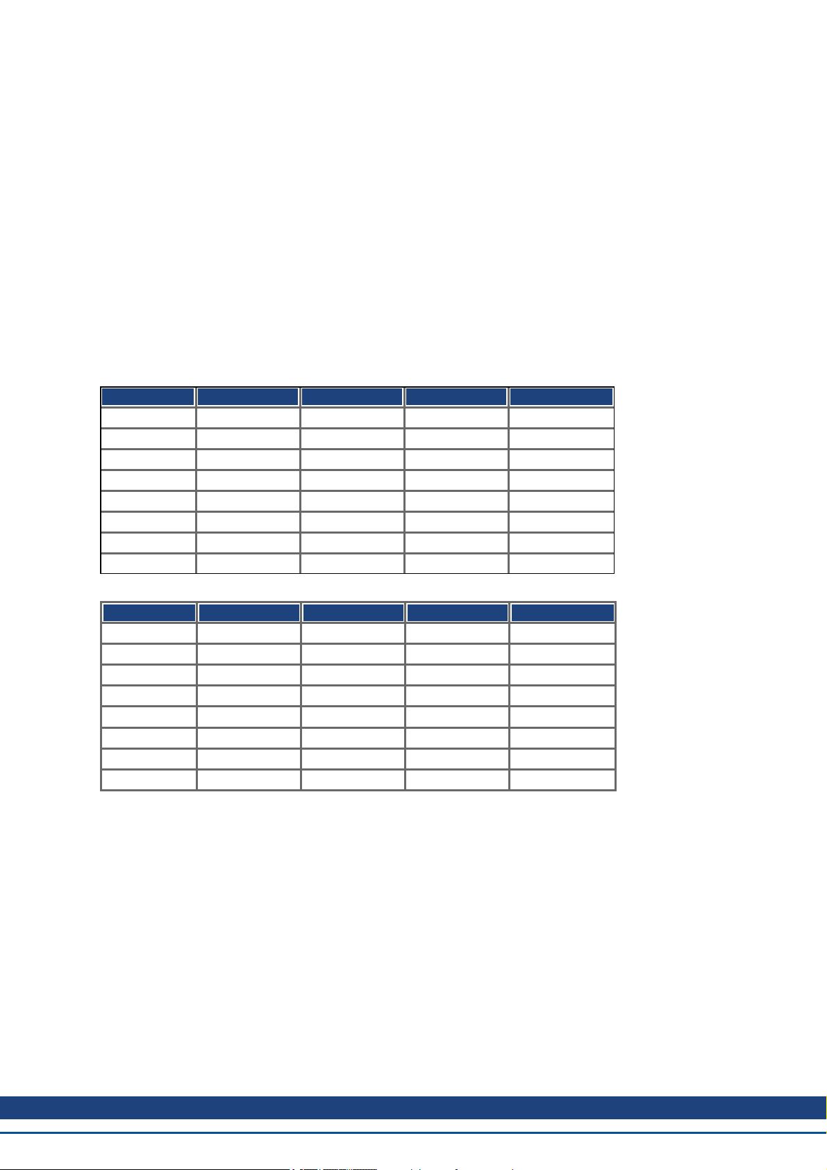
Error reasons to be signaled:If a bit is set to 1 the specified error has occurred. The generic error is signaled at
any error situation.
Bit Description Bit Description
0 generic error 4 communication error(overrun, error state)
1 current 5 device profile specific
2 voltage 6 reserved (always 0)
3 temperature 7 manufacturer specific
Kollmorgen™ | November 2012 47
Page 48

AKD CANopen | 7 CANopen Drive Profile
7.2.1.3 Object 1002h: Manufacturer Status Register (DS301)
The manufacturer status register contains important drive informations.
Index 1002h
Name Manufacturer Status Register
Object code VAR
Data type UNSIGNED32
Category optional
Access R/O
PDO mapping possible
Value range UNSIGNED32
Default value no
The following table shows the bit assignment for the status register:
Bit Description Bit Description
0 1 = Movement (positioning, homing) active 16 1 = Homing move active
1 reference position set 17 reserved
2 1 = reference switch high (home-position) 18 reserved
3 1 = In Position 19 1 = Emergency stop active
4 reserved 20 reserved
5 reserved 21 reserved
6 reserved 22 reserved
7 Active Disabel activated 23 1 = Homing move finished
8 Warning active 24 Power stage deactivating
9 1 = target velocity reached (pp- or pv-Mode) 25 1 = digital input 1 set
10 reserved 26 1 = digital input 2 set
11 1 = Homing error 27 1 = digital input 3 set
12 reserved 28 1 = digital input 4 set
13 1 = Safe Torque Off selected 29 1 = digital input hardware enable set
14 1 = Power stage enabled 30 1 = Wake and Shake action is required
15 1 = Error state 31 Braking, 1 = set points not accepted
48 Kollmorgen™ | November 2012
Page 49

AKD CANopen | 7 CANopen Drive Profile
7.2.1.4 Object 1003h: Predefined Error Field (DS301)
The object 1003h provides an error history with a maximum size of 10 entries.
Subindex 0 contains the number of errors which have occured since the last reset of the error history, either by
startup of the drive or resetting the error history by writing 0 to subindex 0.
A new Emergency-message is written into subindex 1 shifting the old entries one subindex higher. The old content of subindex 8 is lost.
The UNSIGNED32-information written to the subindizes is defined in the field Error Code in the description of the
Emergency Messages (=> p. 42).
Index 1003h
Name pre-defined Error Field
Object code ARRAY
Data type UNSIGNED32
Category optional
Subindex 0
Description Number of entries
Data type UNSIGNED8
Category mandatory
Access R/W
PDO mapping not possible
Value range 0 to 10
Default value 0
Subindex 1 to 10
Description Standard error field (=> p. 42)
Category optional
Access R/O
PDO mapping not possible
Value range UNSIGNED32
Default value no
Kollmorgen™ | November 2012 49
Page 50

AKD CANopen | 7 CANopen Drive Profile
7.2.1.5 Object 1005h: COB-ID of the SYNC Message (DS301)
This object defines the COB-Id of the synchronisation object (SYNC).
Index 1005h
Name COB-ID for the SYNC message
Object code VAR
Data type UNSIGNED32
Category conditional
Access R/W
PDO mapping not possible
Value range UNSIGNED32
Default value no
Bit coded information:
Bit Value Meaning
31 (MSB) X —
30 0 Device not generate SYNC message
1 Device generates SYNC message
29 0 11 Bit ID (CAN 2.0A)
1 29 Bit ID (CAN 2.0B)
28 to 11 X —
0 if Bit 29=0
10 to 0 (LSB) X Bit 0 to 10 of SYNC COB-ID
The device does not support the generation of SYNC-messages and only the 11-bit IDs. So the bits 11 to 30 are
always 0.
7.2.1.6 Object 1006h: Communication Cycle Period (DS301)
This object can be used to define the period (in µs) for the transmission of the SYNC telegram.
Index 1006h
Name Period of the communication cycle
Object code VAR
Data type UNSIGNED32
Category O
Access R/W
PDO mapping not possible
Value range UNSIGNED32
Default value 00h
50 Kollmorgen™ | November 2012
Page 51

AKD CANopen | 7 CANopen Drive Profile
7.2.1.7 Object 1008h: Manufacturer Device Name (DS301)
The device name consists of four ASCII characters in the form Yzzz, whereby Y stands for the mains voltage (L,
M, H or U, e.g. H for High Voltage) zzz stands for the power stage current.
Index 1008h
Name Manufacturer Device Name
Object code VAR
Data type Visible String
Category Optional
Access const
PDO mapping not possible
Value range
Default value no
7.2.1.8 Object 1009h: Manufacturer Hardware Version
This object will be supported in the future.
Index 1009h
Name manufacturer hardware version
Object code VAR
Data type Visible String
Category Optional
Access const
PDO mapping not possible
Value range -
Default value no
7.2.1.9 Object 100Ah: Manufacturer Software Version (DS301)
The object contains the manufacturer software version (here: the CANopen-part of the drive firmware).
Index 100Ah
Name Manufacturer Software Version
Object code VAR
Data type Visible String
Category Optional
Access const
PDO mapping not possible
Value range 0.01 to 9.99
Default value no
Kollmorgen™ | November 2012 51
Page 52

AKD CANopen | 7 CANopen Drive Profile
7.2.1.10 Object 100Ch: Guard Time (DS301)Response monitoring
The arithmetical product of the Objects 100Ch Guard Time and 100Dh Lifetime Factor is the response monitoring
time. The Guard Time is given in milliseconds. The response monitoring is activated with the first Nodeguard
object. If the value of the object Guard Time is set to zero, then the response monitoring is inactive.
Index 100Ch
Name Guard Time
Object code VAR
Data type UNSIGNED16
Category conditional;
mandatory, if heartbeat not supported
Access R/W
PDO mapping not possible
Value range UNSIGNED16
Default value 0
7.2.1.11 Object 100Dh: Lifetime Factor (DS301)
The product of Guard Time and Life Time Factor gives the life time for the nodeguarding protocol. If it’s 0, the protocol is not used.
Index 100Dh
Name Lifetime Factor
Object code VAR
Data type UNSIGNED8
Category conditional; (mandatory, if heartbeat not supported)
Access R/W
PDO mapping not possible
Value range UNSIGNED8
Default value 0
52 Kollmorgen™ | November 2012
Page 53

AKD CANopen | 7 CANopen Drive Profile
7.2.1.12 Object 1010h: Store Parameters (DS301)
This object supports the saving of parameters to a flash EEPROM. Only the subindex 1 for saving of all parameters, which can also be saved in the parameter files via the GUI, is supported.
Index 1010h
Name store parameters (DRV.NVSAVE)
Object code ARRAY
Data type UNSIGNED32
Category optional
Subindex 0
Name number of entries
Object code VAR
Data type UNSIGNED8
Category mandatory
Access R/O
PDO Mapping not possible
Value range 1
Default value 1
Subindex 1
Name save all parameters
Object code VAR
Data type UNSIGNED32
Category mandatory
Access R/W
PDO Mapping not possible
Value range UNSIGNED32
Default value 1
Data definition:
Bit Value Meaning
31 to 2 0 reserved (=0)
1 0 Device does not save parameters autonomously
1 Device does save parameters autonomously
0 0 Device does not save parameters on command
1 Device does not save parameters on command
By read access to subindex 1 the drive provides information about its storage functionality.
This drive provides a constant value of 1 by read access, i.e. all parameters can be saved by writing to Object
1010 sub 1. In general the drive does not save parameters autonomously with the exception of e.g. the special
treatment of the homing of multiturn absolute encoders.
Storing of parameters is only done if a special signature ("save") is written to subindex 1. "save" is equivalent to
the unsigned32 - number 65766173h.
Kollmorgen™ | November 2012 53
Page 54

AKD CANopen | 7 CANopen Drive Profile
7.2.1.13 Object 1011h: Restore Default Parameters DS301
With this object the default values of parameters according to the communication or device profile are restored.
The AKD gives the possibility to restore all default values.
Index 1011h
Name restore default parameters
Object code ARRAY
Data type UNSIGNED32
Category optional
Subindex 0
Name number of entries
Object code VAR
Data type UNSIGNED8
Category mandatory
Access R/O
PDO Mapping not possible
Value range 1
Default value 1
Subindex 1
Name restore all default parameters (DRV.RSTVAR)
Object code VAR
Data type UNSIGNED32
Category mandatory
Access R/W
PDO Mapping not possible
Value range UNSIGNED32
Default value 1 (device restores parameter)
Loading default parameters to the RAM will be done, if a special signature ("load”) is written to subindex 1. "load”
has to be transmitted as unsigned32 - number 64616F6Ch.
54 Kollmorgen™ | November 2012
Page 55

AKD CANopen | 7 CANopen Drive Profile
7.2.1.14 Object 1014h: COB-ID for Emergency Message (DS301)
This object defines the COB-ID of the Emergency message.
Index 1014h
Name COB-ID emergency message
Object code VAR
Data type UNSIGNED32
Category conditional; mandatory, if Emergency is supported
Access R/O
PDO mapping not possible
Value range UNSIGNED32
Default value 80h + Node - ID
7.2.1.15 Object 1016h: Consumer Heartbeat Time
The consumer heartbeat time defines the expected heartbeat cycle time (ms) and must be higher than the corresponding producer heartbeat time configured on the device producing this heartbeat. Monitoring starts after the
reception of the first heartbeat. If the consumer heartbeat time is 0 ms the corresponding entry is not used.
Index 1016h
Name consumer heartbeat time
Object code ARRAY
Data type UNSIGNED32
Category optional
Subindex 0
Description number of entries
Data type UNSIGNED8
Category mandatory
Access R/O
PDO Mapping not possible
Value range 1
Default value 1
Subindex 1
Description Consumer heartbeat time
Category mandatory
Access R/W
PDO Mapping not possible
Value range unsigned 32
Default value no
Definition of the entry value of Subindex 1
MSB LSB
Value reserved (value: 00) Node-ID heartbeat time
Encoded as - UNSIGNED8 UNSIGNED16
Bit
31 24 23 16 15 0
Kollmorgen™ | November 2012 55
Page 56

AKD CANopen | 7 CANopen Drive Profile
7.2.1.16 Object 1017h: Producer Heartbeat Time
The producer heartbeat time defines the cycle time of the heartbeat in ms. If it’s 0, it is not used.
Index 1017h
Name Producer heartbeat time
Object code VAR
Data type UNSIGNED16
Category conditional;
mandatory, if guarding is not supported
Access R/W
PDO mapping not possible
Value range UNSIGNED16
Default value 0
7.2.1.17 Object 1018h: Identity Object (DS301)
The Identity Object contains general device information.
Index 1018h
Name Identity Object
Object code RECORD
Data type Identity
Category mandatory
Subindex 0
Description Number of entries
Data type UNSIGNED8
Category mandatory
Access R/O
PDO mapping not possible
Value range 1 to 4
Default value 4
Subindex 1 is a unique number for a device manufacturer.
Subindex 1
Description Vendor ID
Category mandatory
Access R/O
PDO mapping not possible
Value range UNSIGNED32
Default value 0x6Ah (Danaher Motion)
56 Kollmorgen™ | November 2012
Page 57

AKD CANopen | 7 CANopen Drive Profile
Subindex 2 contains four ASCII - characters, which determine the voltage range and current class of the device.
The voltage range is one character L, M or H for low, medium and high voltage. The next three characters are
showing the continuos current of the drive.
Subindex 2
Description Product Code
Category optional
Access R/O
PDO mapping not possible
Value range e.g. M006 for an MV6 drive
Default value no
Subindex 3 consists of two revision numbers:
l the major revision number in the upper word containing the CAN-version
l the minor revision number is not used in the AKD. The firmware version can be retrieved as a string via object
0x100A or as numbers voa object 0x2018 subindex 1 to 4.
E.g. a value of 0x0014 0000 means CAN-version 0.20.
Subindex 3
Description Revision Number
Category optional
Access R/O
PDO mapping not possible
Value range UNSIGNED32
Default value no
Subindex 4 gives the serial number of the drive. This number contains the following information in it:
l bits 0..14: Board serial number (production in week of year)
l bits 15..20: week of production
l bits 21..24: year of production - 2009
l bits 25..31: ASCII-code of MFR-ID
Subindex 4
Description Serial Number
Category optional
Access R/O
PDO mapping not possible
Value range UNSIGNED32
Default value no
Kollmorgen™ | November 2012 57
Page 58

AKD CANopen | 7 CANopen Drive Profile
7.2.1.18 Object 1026h: OS Prompt
The OS prompt is used to build up an ASCII - communication channel to the drive.
Index 1026h
Name OS Prompt
Object code ARRAY
Data type UNSIGNED8
Category optional
Subindex 0
Description Number of entries
Data type UNSIGNED8
Category mandatory
Access R/O
PDO mapping not possible
Value range 2
Default value 2
Subindex 1 is used to send one character to the drive.
Subindex 1
Description StdIn
Category mandatory
Access W
PDO mapping not possible
Value range UNSIGNED8
Default value —
Subindex 2 is used to receive one character from the drive.
Subindex 2
Description StdOut
Category mandatory
Access R/O
PDO mapping not possible
Value range UNSIGNED8
Default value 0
58 Kollmorgen™ | November 2012
Page 59

AKD CANopen | 7 CANopen Drive Profile
7.2.2 Manufacturer specific objects
7.2.2.1 Object 2014-2017h: 1st-4th Mask 1 to 4 for Transmit-PDO
In order to reduce the bus loading with event-triggered PDOs, masking can be used to switch off the monitoring
for individual bits in the PDO. In this way it can be arranged, for instance, that actual position values are only signaled once per turn.
This Object masks the PDO-channels 1 to 4. If only two bytes have been defined in a PDO, then it masks just
two bytes, although 4 bytes of mask information have been transmitted.
An activated bit in the mask means that monitoring is active for the corresponding bit in the PDO.
Index 2014h
2015h
2016h
2017h
Name tx_mask 1 to 4
Object code ARRAY
Data type UNSIGNED32
Subindex 1
Description tx_mask1 to 4_low
Mode independent
Access R/W
PDO mapping not possible
Unit —
Value range UNSIGNED32
Default value FFFFFFFFh
Subindex 2
Description tx_mask1 to 4_high
Mode independent
Access R/W
PDO mapping not possible
Unit —
Value range UNSIGNED32
Default value FFFFFFFFh
Kollmorgen™ | November 2012 59
Page 60

AKD CANopen | 7 CANopen Drive Profile
7.2.2.2 Object 2018h: Firmware Version
This object gives all information regarding the firmware version.
Example: Firmware version M_01_00_01_005 would show the numbers 1, 0, 1, 5 in the sub-indices 1 to 4.
Index 2018h
Name firmware version
Object code ARRAY
Data type UNSIGNED16
Subindex 1
Description major version
Mode independent
Access R/O
PDO mapping not possible
Unit —
Value range UNSIGNED16
Default value 0
Subindex 2
Description minor version
Mode independent
Access R/O
PDO mapping not possible
Unit —
Value range UNSIGNED16
Default value 0
Subindex 3
Description revision
Mode independent
Access R/O
PDO mapping not possible
Unit —
Value range UNSIGNED16
Default value 0
Subindex 4
Description branch revision
Mode independent
Access R/O
PDO mapping not possible
Unit —
Value range UNSIGNED16
Default value 0
60 Kollmorgen™ | November 2012
Page 61

AKD CANopen | 7 CANopen Drive Profile
7.2.2.3 Object 2026h: ASCII Channel
This object is used to build up an ASCII - communication channel to the drive with 4-byte ASCII-strings.
Index 2026h
Name ASCII Channel
Object code ARRAY
Data type Visible String
Category optional
Subindex 0
Description Number of entries
Data type UNSIGNED8
Category mandatory
Access R/O
PDO mapping not possible
Value range 2
Default value 2
Subindex 1 is used to send four ASCII-characters to the drive.
Subindex 1
Description Command
Category mandatory
Access wo
PDO mapping no
Value range Visible String
Default value —
Subindex 2 is used to receive four characters from the drive.
Subindex 2
Description Response
Category mandatory
Access R/O
PDO mapping no
Value range Visible String
Default value -
Kollmorgen™ | November 2012 61
Page 62

AKD CANopen | 7 CANopen Drive Profile
7.2.2.4 Object 20A0h: Latch position 1, positive edge
This object is used to output the position or a time, depending on CAP0.MODE, at which the first positive edge
occurred on a signal, which can be configured with the command CAP0.TRIGGER. The latch enable must be
active for that purpose(see object 20A4 and 20A5). With CAP0.MODE = 3 the latched position of the encoder
index pulse is transferred via this object.
Index 20A0h
Name Latch position 1, positive edge, CAP0.PLFB
Time capture, CAP0.T
Object code VAR
Data type INTEGER32
Category optional
Access R/O
PDO mapping possible
Value range INTEGER32
Default value 0
7.2.2.5 Object 20A1h: Latch position 1, negative edge
This object is used to output the position or a time, depending on CAP0.MODE, at which the first negative edge
occurred on a signal, which can be configured with the command CAP0.TRIGGER. The latch enable must be
active for that purpose(see object 20A4 and 20A5).
Index 20A1h
Name Latch position 1, negative edge, CAP0.PLFB
Time capture, CAP0.T>
Object code VAR
Data type INTEGER32
Category optional
Access R/O
PDO mapping possible
Value range INTEGER32
Default value 0
7.2.2.6 Object 20A2h: Latch position 2, positive edge
This object is used to output the position or a time, depending on CAP1.MODE, at which the first positive edge
occurred on a signal, which can be configured with the command CAP1.TRIGGER. The latch enable must be
active for that purpose(see object 20A4 and 20A5).
Index 20A2h
Name Latch position 2, positive edge, CAP1.PLFB
Time capture, CAP1.T
Object code VAR
Data type INTEGER32
Category optional
Access R/O
PDO mapping possible
Value range INTEGER32
Default value 0
62 Kollmorgen™ | November 2012
Page 63

AKD CANopen | 7 CANopen Drive Profile
7.2.2.7 Object 20A3h: Latch position 2, negative edge
This object is used to output the position or a time, depending on CAP0.MODE, at which the first negative edge
occurred on a signal, which can be configured with the command CAP0.TRIGGER. The latch enable must be
active for that purpose(see object 20A4 and 20A5).
Index 20A3h
Name Latch position 2, negative edge, CAP1.PLFB
Time capture, CAP1.T
Object code VAR
Data type INTEGER32
Category optional
Access R/O
PDO mapping possible
Value range INTEGER32
Default value 0
7.2.2.8 Object 20A4h: Latch Control Register
The latch control register is used to enable the latch monitoring of the capture engines 0 and 1. The latch is enabled with a 1 signal and disabled with a 0 signal. Whether or not a latch event has occurred can be recognised by
the latch status register (object 20A5).
Index 20A4h
Name Latch Control Register
Object code VAR
Data type UNSIGNED16
Category optional
Access rww
PDO mapping possible
Value range 0 to 15
Default value 0
Bit Value (bin) Value (hex) Description
0 00000000 00000001 xx01 Enable extern latch 1 (positive rise)
1 00000000 00000010 xx02 Enable extern latch 1 (negative rise)
2 00000000 00000100 xx04 Enable extern latch 2 (positive rise)
3 00000000 00001000 xx08 Enable extern latch 2 (negative rise)
4 00000000 00010000 xx10 Enable latch of encoder index pulse
5 to 7 Reserve
8 00000001 00000000 01xx Read external latch 1 (positive rise)
9 00000010 00000000 02xx Read external latch 1 (negative rise)
10 00000011 00000000 03xx Read external latch 2 (positive rise)
11 00000100 00000000 04xx Read external latch 2 (negative rise)
12 00000101 00000000 05xx Read latched position of encoder index pulse
13 to
Reserve
15
Kollmorgen™ | November 2012 63
Page 64

AKD CANopen | 7 CANopen Drive Profile
7.2.2.9 Object 20A5h: Latch Status Register
The latch status register is used to look for the states of the capture engines 0 and 1.
Index 20A5h
Name Latch Status Register
Object code VAR
Data type UNSIGNED16
Category optional
Access rwr
PDO mapping possible
Value range -
Default value 0
Bit Value (bin) Value (hex) Description
0 00000000 00000001 zz01 External latch 1 valid (positive rise)
1 00000000 00000010 zz02 External latch 1 valid (negative rise)
2 00000000 00000100 zz04 External latch 2 valid (positive rise)
3 00000000 00001000 zz08 External latch 2 valid (negative rise)
4 00000000 00010000 z10 Latched position of encoder index pulse valid (positive rise)
5 to 7 Reserve
8 to 11 00000001 00000000 z1zz Acknowledge value external latch 1 (positive rise)
00000010 00000000 z2zz Acknowledge value external latch 1 (negative rise)
00000011 00000000 z3zz Acknowledge value external latch 2 (positive rise)
00000100 00000000 z4zz Acknowledge value external latch 2 (negative rise)
00000101 00000000 z5zz Acknowledge value of latched position of encoder index
pulse (positive rise)
12 to 15 00010000 00000000 1zzz State Digital Input 4
00100000 00000000 2zzz State Digital Input 3
01000000 00000000 4zzz State Digital Input 2
10000000 00000000 8zzz State Digital Input 1
7.2.2.10 Object 20A6h: Latch position 1, positive or negative edge
This object is used to output the position or a time, depending on CAP0.MODE, at which the first positive or negative edge occurred on a signal, which can be configured with the command CAP0.TRIGGER.
The latch enable must be active for that purpose (see object 20A4 and 20A5).
Index 20A6h
Name Latch position 1, positive or negative, CAP0.PLFB
Object code VAR
Data type INTEGER32
Category optional
Access ro
PDO mapping possible
Value range INTEGER32
Default value 0
64 Kollmorgen™ | November 2012
Page 65

AKD CANopen | 7 CANopen Drive Profile
7.2.2.11 Object 20B8h: Reset of changed input information
This object is used in PDOs to reset the state change information for the digital inputs shown in the Bits 24 to 30
in the object 60FD. Bit 0 to 6 are used to reset the information of the digital input 1 to 7.
Index 20B8h
Name Reset of changed input information
Object code VAR
Data type UNSIGNED16
Category optional
Access rw
PDO mapping possible
Value range UNSIGNED16
Default value 0
Kollmorgen™ | November 2012 65
Page 66

AKD CANopen | 7 CANopen Drive Profile
7.2.2.12 Object 345Ah: Brake Control
These objects implement the possibility to control the brake directly, overriding the drive logic. When the brake
state is controlled by the fieldbus, the drive state (enabled, disabled, faulted) will have no effect on the brake - the
fieldbus will be in control.
Applying or releasing the brake at the wrong time can be a safety hazard and can
destroy your mechanic as well as drive or motor. Unexpected behaviour might
be possible. It is the responsibility of the customer using this mode to use this
function appropriately.
When fieldbus control is disabled, the drive will control the brake as defined by existing AKD brake related parameters. As soon as fieldbus control is enabled, the Brake Command received over the field bus will take effect. So,
if the Brake Command is set to APPLY and the current state is RELEASE, the brake will begin to apply .
The default value of the fieldbus control will be disabled, so that the drive is always in control until the fieldbus is
operational. It is recommended that this bit remain 0 except for special operating conditions where the fieldbus
will control the brake. When fieldbus communication is lost, the drive will regain control of the brake if the fieldbus
had previously taken control.
Enable Fieldbus
Control
Serious Failur econdition present
Brake Command
Fieldbus Control
Status
Controlled
by...
Final Brake
State
0 x x 0 Drive Drive
1* no 0 1 Fieldbus Applied
1* no 1 1 Fieldbus Released
x yes any 0 Drive Drive
1* indicates that a rising edge was seen since the last time the drive applied the brake
Index 345Ah
Name Brake Control
Object code ARRAY
Data type UNSIGNED16
Category optional
Defined sub-indices
Subindex 0
Name number of entries
Data type UNSIGNED8
Category mandatory
Access R/O
PDO Mapping not possible
Value Range 2
Default Value 2
66 Kollmorgen™ | November 2012
Page 67

AKD CANopen | 7 CANopen Drive Profile
Subindex 1
Name Brake Control Command
Category optional
Access R/W
PDO Mapping possible
Value Range UNSIGNED16
Default Value 0
With subindex 1 the brake is controlled. Bit definition:
Bit Name Description
0 Enable fieldbus control 0 - brake is not controlled via this object
1 - enable fieldbus control via this object. This function works edge triggered,
i.e. this bit has to have a 0 -> 1 transition to activate the brake control functionality. After a fault the functionality is reset and has to be activated again.
The activation can be controlled by subindex 2 bit 0.
1 Brake Command This command bit is only active, if the functionality was activated via bit 0.
The function is as follows:
0 - apply the brake
1 - release the brake
Subindex 2
Name Brake Status Response
Category optional
Access R/O
PDO Mapping possible
Value Range UNSIGNED16
Default Value 0
With subindex 2 the brake status can be checked. Bit definition:
Bit Name Description
0 Fieldbus control Status 0 - brake control via 0x345A is disabled or not possible due to drive failure.
1 - enable fieldbus control via this object. This function works edge triggered,
i.e. this bit has to have a 0 -> 1 transition to activate the brake control functionality. After a fault the functionality is reset and has to be activated again.
The activation can be controlled by subindex 2 bit 0.
1 Brake Status 0 - apply the brake
1 - release the brake
Note: When the brake is applied or released, there is a time delay
MOTOR.TBRAKEAPP or MOTOR.TBRAKEREL, after the receipt of the
command before this status bit changes. The status is always reported: it is
not affected by fieldbus control.
2 STO Status 0 - STO is not active (drive may be enabled)
1 - STO is active (drive can not be enabled)
3 HW Enable Status 0 - HW enable is disabled, drive function can not be enabled
1 - HW enable is enabled, drive function can be enabled
Kollmorgen™ | November 2012 67
Page 68

AKD CANopen | 7 CANopen Drive Profile
7.2.2.13 Object 3474h: Parameters for digital inputs
This set of objects is used to set extended parameters for some digital input functions. The parameters can be
used for different DINx.MODEs. Therefore thescaling might be different or no scaling is used at all.
Two subindices build an access object to one of these parameters, because they are 64-bit numbers internally,
e.g. object 3474 sub 1 gives access to the low 32 bits of DIN1.PARAM whereas 3474 sub 8 gives access to the
high 32 bits.
If access to the whole 64 bit number is needed the higher bits must be written first. The access to the lower 32
bits then writes the parameter. If the to be written value fits into 32 bit, only the lower part needs to be written.
The most-significant bit is then taken as sign-bit for the number.
Index 3474h
Name DINx.PARAM
Object code Array
Data type UNSIGNED32
Category optional
Subindex 0
Description number of entries
Category mandatory
Access R/O
PDO mapping not possible
Value range 0xE
Default value 0xE
Subindex 1 to 7
Description DINx.PARAM low 32 bits, x = 1 .. 7
Category optional
Access R/W
PDO mapping not possible
Value range UNSIGNED32
Default value 0
Subindex 8 to 0xE
Description DINx.PARAM high 32 bits, x = 1 .. 7
Category optional
Access R/W
PDO mapping not possible
Value range UNSIGNED32
Default value 0
68 Kollmorgen™ | November 2012
Page 69

AKD CANopen | 7 CANopen Drive Profile
7.2.2.14 Object 3475h: Parameters for digital outputs
This set of objects is used to set extended parameters for some digital output functions. The parameters can be
used for different DOUTx.MODEs. Therefore the scaling might be different or no scaling is used at all.
Two subindices build an access object to one of these parameters, because they are 64-bit numbers internally,
e.g. object 3475 sub 1 gives access to the low 32 bits of DOUT1.PARAM whereas 3475 sub 3 gives access to
the high 32 bits.
If access to the whole 64 bit number is needed the higher bits must be written first. The access to the lower 32
bits then writes the parameter. If the to be written value fits into 32 bit, only the lower part needs to be written.
The most-significant bit is then taken as sign-bit for the number.
Index 3475h
Name DOUTx.PARAM
Object code Array
Data type UNSIGNED32
Category optional
Subindex 0
Description number of entries
Category mandatory
Access R/O
PDO mapping not possible
Value range 0x4
Default value 0x4
Subindex 1 to 2
Description DOUTx.PARAM low 32 bits, x = 1 .. 2
Category optional
Access R/W
PDO mapping not possible
Value range UNSIGNED32
Default value 0
Subindex 3 to 4
Description DOUTx.PARAM high 32 bits, x = 1 .. 2
Category optional
Access R/W
PDO mapping not possible
Value range UNSIGNED32
Default value 0
Kollmorgen™ | November 2012 69
Page 70

AKD CANopen | 7 CANopen Drive Profile
7.2.2.15 Object 3496h: Fieldbus synchronization parameters
This set of objects is used to set or read parameters for the fieldbus synchronization used in the interpolated position mode (7) and the cyclic-modes 8 etc. The synchronization between a fieldbus master and the AKD is similar
in all the supported fieldbus systems.
The AKD internal 16[kHz] interrupt function is responsible for calling the PLL function. This PLL function is called
once per fieldbus cycle (set by object 60C2 sub 1 and 2).If the fieldbus sample period is for example 1[ms], the
PLL code is called every 16th time of the 16[kHz] IRQ of the AKD.
Once in a fieldbus sample the SYNC-telegram must arrive, which resets a PLL counter in the Drive. After some
time the already mentioned PLL function is called and reads back the time from that PLL counter.
Depending on the measured time the PLL function extends (in case that the measured time is too low) or lowers
(in case that the measured time is too high) the sample time of the upcoming 16[kHz] tasks for one fieldbus sample by a selectable value (object 3496 sub 4) in order to move the PLL function closer to the expected distance
(object 3496 sub 1).
Beside the objects mentioned here the parameter FBUS.SAMPLEPERIOD is important, which is set by object
60C2 sub 1 and 2.This setting is required in order to share the fieldbus sample time with the slave. This information is e.g. needed for being able to call the AKD internal PLL function once per fieldbus sample.
Index 3496h
Name FBUS synchronization parameters
Object code Array
Data type UNSIGNED32
Category optional
Subindex 0
Description number of entries
Category mandatory
Access R/O
PDO mapping not possible
Value range 0x4
Default value 0x4
Subindex 1
Description FBUS.SYNCDIST
Category optional
Access R/W
PDO mapping not possible
Value range UNSIGNED32
Default value 320000 [ns]
Sub 1 is the expected time distance in nano seconds between clearing the PLL counter and calling the PLL function.
Subindex 2
Description FBUS.SYNCACT
Category optional
Access R/W
PDO mapping not possible
Value range UNSIGNED32
Default value 320000 [ns]
Sub 2 is the actual time distance in nano seconds between clearing the PLL counter and calling the PLL function.
70 Kollmorgen™ | November 2012
Page 71

AKD CANopen | 7 CANopen Drive Profile
Subindex 3
Description FBUS.SYNCWND
Category optional
Access R/W
PDO mapping not possible
Value range UNSIGNED32
Default value 70000 [ns]
Sub 3 is a window, which is used in order to consider the drive as being synchronized. The AKD is considered as
synchronized in the following case:
FBUS.SYNCDIST – FBUS.SYNCWND < FBUS.SYNCACT < FBUS.SYNCDIST + FBUS.SYNCWND
Subindex 4
Description FBUS.COMPTIME
Category optional
Access R/W
PDO mapping not possible
Value range UNSIGNED32
Default value 150 [ns]
Sub 4 value indicates the time, which is used for extending or lowering the sample rate of the AKD internal 16
[kHz] IRQ, which is responsible for calling the PLL function. The default sample time is 32 * 1/16[kHz] = 2[ms].
The sample time of the AKD high prior interrupt is determined by
62.5[µs] – FBUS.COMPTIME if FBUS.SYNCACT > FBUS.SYNCDIST.
The sample time of the AKD high prior interrupt is determined by
62.5[µs] + FBUS.COMPTIME if FBUS.SYNCACT < FBUS.SYNCDIST.
Kollmorgen™ | November 2012 71
Page 72

AKD CANopen | 7 CANopen Drive Profile
7.2.3 Profile specific objects
7.2.3.1 Object 60B8h: Touch probe function
This object indicates the configured function of the touch probe.
Index 60B8h
Name Touch probe function
Object code Variable
Data type UNSIGNED16
Category optional
Access R/W
PDO Mapping yes
Value range UNSIGNED16
Default value 0
Definition of the possible functions:
Bit Value Meaning
0 0 Switch off touch probe 1
1 Enable touch probe 1
1 0 Trigger first event
1 Continuous
3, 2 00b Trigger with touch probe 1 input
01b Trigger with zero impulse signal or position encoder
10b Touch probe source as defined in object 60D0h, sub-index 01h
11b reserved
4 0 Switch off sampling at positive edge of touch probe 1
1 Enable sampling at positive edge of touch probe 1
5 0 Switch off sampling at negative edge of touch probe 1
1 Enable sampling at negative edge of touch probe 1
6, 7 - User-defined (e.g. for testing)
8 0 Switch off touch probe 2
1 Enable touch probe 2
9 0 Trigger first event
1 continuous
11, 10 00b Trigger with touch probe 2 input
01b Trigger with zero impulse signal or position encoder
10b Touch probe source as defined in object 60D0h, sub-index 02h
11b reserved
12 0 Switch off sampling at positive edge of touch probe 2
1 Enable sampling at positive edge of touch probe 2
13 0 Switch off sampling at negative edge of touch probe 2
1 Enable sampling at negative edge of touch probe 2
14, 15 - User-defined (e.g. for testing)
72 Kollmorgen™ | November 2012
Page 73

7.2.3.2 Object 60B9h: Touch probe status
This object indicates the status of the touch probe.
Index 60B9h
Name Touch probe status
Object code Variable
Data type UNSIGNED16
Category optional
Access R/O
PDO Mapping yes
Value range UNSIGNED16
Default value 0
Definition of the status:
Bit Value Meaning
0 0 Touch probe 1 is switched off
1 Touch probe 1 is enabled
1 0 Touch probe 1 no positive edge value stored
1 Touch probe 1 positive edge position stored
2 0 Touch probe 1 no negative edge value stored
1 Touch probe 1 negative edge position stored
3 to 5 0 reserved
6, 7 - User-defined (e.g. for testing)
8 0 Touch probe 2 is switched off
1 Touch probe 2 is enabled
9 0 Touch probe 2 no positive edge value stored
1 Touch probe 2 positive edge position stored
10 0 Touch probe 2 no negative edge value stored
1 Touch probe2 negative edge position stored
11 to 13 0 reserved
14, 15 - User-defined (e.g. for testing)
AKD CANopen | 7 CANopen Drive Profile
Kollmorgen™ | November 2012 73
Page 74

AKD CANopen | 7 CANopen Drive Profile
7.2.3.3 Object 60BAh: Touch probe 1 positive edge
This object provides the position value of the touch probe 1 at positive edge.
Index 60BAh
Name Touch probe 1 positive edge
Object code Variable
Data type INTEGER32
Category optional
Access R/O
PDO Mapping yes
Value range INTEGER32
Default value no
7.2.3.4 Object 60BBh: Touch probe 1 negative edge
This object provides the position value of the touch probe 1 at negative edge.
Index 60BBh
Name Touch probe 1 negative edge
Object code Variable
Data type INTEGER32
Category optional
Access R/O
PDO Mapping yes
Value range INTEGER32
Default value no
7.2.3.5 Object 60BCh: Touch probe 2 positive edge
This object provides the position value of the touch probe 2 at positive edge.
Index 60BCh
Name Touch probe 2 positive edge
Object code Variable
Data type INTEGER32
Category optional
Access R/O
PDO Mapping yes
Value range INTEGER32
Default value no
74 Kollmorgen™ | November 2012
Page 75

AKD CANopen | 7 CANopen Drive Profile
7.2.3.6 Object 60BDh: Touch probe 2 negative edge
This object provides the position value of the touch probe 2 at negative edge.
Index 60BDh
Name Touch probe 2 negative edge
Object code Variable
Data type INTEGER32
Category optional
Access R/O
PDO Mapping yes
Value range INTEGER32
Default value no
7.2.3.7 Object 60D0h: Touch probe source
This object provides the source of the touch probe function, when the dedicated bits 2/3 or 10/11 of the touch
probe function (object 60B8h) are set accordingly.
Index 60D0h
Name Touch probe source
Object code Array
Data type Integer 16
Category optional
Subindex 0
Description Highest sub-index supported
Category mandatory
Access R/O
PDO mapping not possible
Value range 2
Default value 2
Subindex 1
Description Touch probe 1 source
Category mandatory
Access R/W
PDO mapping not possible
Value range -11 to -1, 1 to 5
Default value 1
Subindex 2
Description Touch probe 2 source
Category mandatory
Access R/W
PDO mapping not possible
Value range -11 to -1, 1 to 5
Default value 1
Kollmorgen™ | November 2012 75
Page 76

AKD CANopen | 7 CANopen Drive Profile
7.2.3.8 Object 60FDh: Digital inputs (DS402)
This index defines simple digital inputs for drives. The manufacturer bits 16 to 22 are used to mirror the digital
inputs 1 to 7. The manufacturer bits 24 to 30 are used to show the change of the state of the digital inputs 1 to 7.
Index 60FDh
Name digital inputs
Object code VAR
Data type UNSIGNED32
Category optional
Access R/O
PDO mapping possible
Value range UNSIGNED32
Default value 0
31 16 15 4
manufacturer specific reserved interlock home
3 2 1 0
switch
pos. limit
switch
neg. limit
switch
MSB LSB
76 Kollmorgen™ | November 2012
Page 77

AKD CANopen | 7 CANopen Drive Profile
7.2.3.9 Object 60FEh: Digital outputs (DS402)
This index defines simple digital outputs for drives. The manufacturer bits 16 and 17 are used to
mirror the digital outputs 1 and 2.
Index 60FEh
Name digital outputs
Object code Array
Data type UNSIGNED32
Category optional
Subindex 0
Description number of entries
Category mandatory
Access R/O
PDO mapping not possible
Value range 2
Default value 2
Subindex 1
Description physical outputs
Category mandatory
Access R/W
PDO mapping possible
Value range UNSIGNED32
Default value 0
Subindex 2
Description bit mask
Category optional
Access R/W
PDO mapping not possible
Value range UNSIGNED32
Default value 0
31 18 17 16 15 1 0
manufacturer specific DOUT2 DOUT1 reserved set brake
MSB LSB
Kollmorgen™ | November 2012 77
Page 78

AKD CANopen | 7 CANopen Drive Profile
7.2.3.10 Object 6502h: Supported drive modes (DS402)
A drive can support more then one and several distinct modes of operation. This object gives an overview of the
implemented operating modes in the device. This object is read only.
Index 6502h
Name supported drive modes
Object code VAR
Data type UNSIGNED32
Category optional
Access R/O
PDO mapping not possible
Value range UNSIGNED32
Default value 0x65 (ip hm pv pp)
31 16 15 7
6 5 4 3 2 1 0
manufacturer specific reserved ip hm reserved tq pv vl pp
MSB LSB
78 Kollmorgen™ | November 2012
Page 79

AKD CANopen | 7 CANopen Drive Profile
7.3 PDO Configuration
PDOs are used for process data communication. There are two types of PDOs: Receive PDOs (RPDOs) and
transmit PDOs (TPDOs).
The content of the PDOs is pre-defined (see descriptions on pages=> p. 80 and => p. 83). If the data content is
not appropriate for a special application the data objects in the PDOs can be remapped freely.
One data entry in the PDOs looks like this:
MSB LSB
index (16 bit) Subindex (8 bit) data length in bits (8 bit)
The configuration procedure for a free mapping of a PDO looks like this (example for TPDO1):
1. Stop possible transmission of the PDO.
COB-ID Control
byte
Low byte High byte index Data Comment
601 23 ´00 18 01h 81 01 00 C0 Switch-off COB-Id
2. Delete the actual mapping of the PDO by writing a 0 to the subindex 0 of the mapping Object.
COB-ID Control
byte
Low byte High byte index Data Comment
601 2F ´00 1A 00h 00 00 00 00 Delete actual mapping
3. Build the mapping with object dictionary objects (see page => p. 119)) which are mappable, e.g.
COB-ID Control
byte
Low byte High byte index Data Comment
601 23 00 1A 01h 10 00 41 60 1st entry:
601 23 00 1A 02h 20 00 02 10 2nd entry:
3. Write the number of mapped objects to subindex 0 of the mapping Object.
Index Sub-
Index Sub-
Index Sub-
CANopen statusword
with 16 bits
Manufacturer status
with 32 bits
COB-ID Control
byte
Low byte High byte index Data Comment
601 2F 00 1A 00h 02 00 00 00 Check for the right
Mapping shall be done before the network management is switched to OPERATIONAL.
Index Sub-
number of entries
Kollmorgen™ | November 2012 79
Page 80

AKD CANopen | 7 CANopen Drive Profile
7.3.1 Receive PDOs (RXPDO)
Four Receive PDOs can be configured in the drive:
l - configuration of the communication (Objects 1400-1403h)
l - configuration of the PDO-contents (mapping, Objects 1600-1603h)
7.3.1.1 Objects 1400-1403h: 1st - 4th RXPDO communication parameter (DS301)
Index 1400h to 1403h for RXPDO 1 to 4
Name receive PDO parameter
Object code RECORD
Data type PDO CommPar
Category mandatory
Defined sub-indices
Subindex 0
Name number of entries
Data type UNSIGNED8
Category mandatory
Access R/O
PDO Mapping not possible
Value Range 2
Default Value 2
Subindex 1
Name COB-ID used by PDO
Category mandatory
Access R/W
PDO Mapping not possible
Value Range UNSIGNED32
Default Value
Index 1400h: 200h + Node-ID Index 1401h: 300h + Node-ID
Index 1402h: 400h + Node-ID Index 1403h: 500h + Node-ID
Subindex 1 contains the COB-Id of the PDO as a bit coded information:
Bit Value Meaning
31 0 PDO exists/is valid
1 PDO does not exist/is not valid
30 0 RTR allowed on this PDO, not to be used (Can in Automation organisation)
1 RTR not allowed on this PDO
29 0 11 bit-ID (CAN 2.0A)
1 29 bit-ID (CAN 2.0B), not supported
28 to 11 X Identifier-bits with 29 bit-ID, not relevant
10 to 0 X Bits 10-0 of COB-ID
80 Kollmorgen™ | November 2012
Page 81

AKD CANopen | 7 CANopen Drive Profile
Subindex 2
Name transmission type
Category mandatory
Access R/W
PDO Mapping not possible
Value Range UNSIGNED8
Default Value FFh
Subindex 2 contains the transmission type of the PDO. There are two ways of setting:
l the value FFh or 255 for event-triggered PDO, which is directly interpreted by reception and taken into
actions,
l values from 0 to 240, which cause a SYNC-telegram-controlled interpretation of the PDO
contents. Values of 1 to 240 mean, that 0 to 239 SYNC-telegrams are ignored, before one is interpreted. The
value 0 means, that only the next SYNC-telegram is interpreted.
7.3.1.2 Objects 1600-1603h: 1st - 4th RXPDO mapping parameter (DS301)
Index 1600h - 1603h for RXPDO 1 .. 4
Name receive PDO mapping
Object Code RECORD
Data Type PDO Mapping
Category mandatory
Subindex 0
Name number of entries
Data type UNSIGNED8
Category mandatory
Access R/W
PDO Mapping not possible
Value Range 0: PDO is not active
1 - 8: PDO activated, mappings are taken only byte-wise
Default Value PDO1: 1
PDO2: 2
PDO3: 2
PDO4: 2
Subindex 1 - 8
Name PDO - mapping for the n-th application object
Category Conditional, depends on number and size of object be mapped
Access R/W
PDO Mapping not possible
Value Range UNSIGNED32
Default Value See below
Kollmorgen™ | November 2012 81
Page 82

AKD CANopen | 7 CANopen Drive Profile
7.3.1.3 Default RXPDO definition
RXPDO 1:
Subindex Value Meaning
0 1 One PDO-mapping entry
1 60 40 00 10 Control word
RXPDO 2:
Subindex Value Meaning
0 2 Two PDO-mapping entries
1 60 40 00 10 Control word
2 60 60 00 08 Modes of Operation
RXPDO 3:
Subindex Value Meaning
0 2 Two PDO-mapping entries
1 60 40 00 10 Control word
2 60 7A 00 20 Target Position (Mode PP)
RXPDO 4:
Subindex Value Meaning
0 2 Two PDO-mapping entries
1 60 40 00 10 Control word
2 60 FF 00 20 Target Velocity (Mode PV)
82 Kollmorgen™ | November 2012
Page 83

AKD CANopen | 7 CANopen Drive Profile
7.3.2 Transmit PDOs (TXPDO)
Four Transmit PDOs can be configured in the drive:
l - configuration of the communication (Objects 1800-1803h)
l - configuration of the PDO-contents (mapping, Objects 1A00-1A03h)
7.3.2.1 Objects 1800-1803h: 1st - 4th TXPDO communication parameter (DS301)
Index 1800h to 1803h for TXPDO 1 to 4
Name transmit PDO parameter
Object code RECORD
Data type PDO CommPar
Category mandatory
Subindex 0
Name number of entries
Data type UNSIGNED8
Category mandatory
Access R/O
PDO Mapping not possible
Value Range 5
Default Value 5
Subindex 1
Name COB-ID used by PDO
Category mandatory
Access R/W
PDO Mapping not possible
Value Range UNSIGNED32
Default Value Index 1800h: 180h + Node-IDIndex 1801h: 280h + Node-ID
Index 1802h: 380h + Node-ID Index 1803h: 480h + Node-ID
Subindex 2
Name transmission type
Category mandatory
Access R/W
PDO Mapping not possible
Value Range UNSIGNED8
Default Value FFh
Subindex 3
Name inhibit time
Category optional
Access R/W
PDO Mapping not possible
Value Range UNSIGNED16 (n*1/10ms)
Default Value 0h
Kollmorgen™ | November 2012 83
Page 84

AKD CANopen | 7 CANopen Drive Profile
Subindex 4
Name reserved
Category optional
Access R/W
PDO Mapping not possible
Value Range 0
Default Value 0
Subindex 5
Name event timer
Category optional
Access R/W
PDO Mapping not possible
Value Range UNSIGNED16 (0=not used, ms)
Default Value 0h
Subindex 1 contains the COB-Id of the PDO as a bit coded information:
Bit-Number Value Meaning
31 0 PDO exists/is valid
1 PDO does not exist/is not valid
30 0 RTR allowed on this PDO, not supported
1 RTR not allowed on this PDO, not supported
29 0 11 bit-ID (CAN 2.0A)
1 29 bit-ID (CAN 2.0B), not supported
28 to 11 X Identifier-bits with 29 bit-ID, not relevant
10 to 0 X Bits 10-0 of COB-ID
Subindex 2 contains the transmission type of the PDO. There are two ways of setting:
l A value of FFh or 255d for an event-triggered PDO, which is sent immediately after a change in the mapped
application objects. Setting of Subindex 3 or 5 has an influence on the sending of a PDO. With Subindex 3
you can configure, in which minimal time the so configured Transmit-PDOs are sent, if PDO-data contents
change (reduction of bus-load). With Subindex 5 (event time) a timer is used, which is reset with every eventtriggered sending of this PDO. If there is no change of the PDO-content in this time, the PDO is sent caused
by this timer event.
l Values from 0 to 240 cause a SYNC-Telegram controlled sending of the PDO.
Values from 1 to 240 define how often the SYNC-telegram leads to a sending of a PDO.
The value 0 means, that only the next SYNC-telegram leads to a sending of the so
configured PDOs.
84 Kollmorgen™ | November 2012
Page 85

AKD CANopen | 7 CANopen Drive Profile
7.3.2.2 Objects 1A00-1A03h: 1st - 4th TXPDO mapping parameter (DS301)
Index 1A00h - 1A03h for TXPDO 1 .. 4
Name transmit PDO mapping
Object Code RECORD
Data Type PDO Mapping
Category mandatory
Subindex 0
Name number of mapped application objects in PDO
Data type UNSIGNED8
Category mandatory
Access R/W
PDO Mapping not possible
Value Range 0: PDO is not active
1 - 8: PDO activated, mappings are taken only byte-wise
Default Value PDO1: 1
PDO2: 2
PDO3: 2
PDO4: 2
Subindex 1 - 8
Name PDO - mapping for the n-th application object
Category Conditional, depends on number and size of object be mapped
Access R/W
PDO Mapping not possible
Value Range UNSIGNED32
Default Value See below
Kollmorgen™ | November 2012 85
Page 86

AKD CANopen | 7 CANopen Drive Profile
7.3.2.3 Default TXPDO definition
TXPDO 1:
Subindex Value Meaning
0 1 One PDO-mapping entry
1 60 41 00 10 Status word
TXPDO 2:
Subindex Value Meaning
0 2 Two PDO-mapping entries
1 60 41 00 10 Status word
2 60 61 00 08 Modes of Operation display
TXPDO 3:
Subindex Value Meaning
0 2 Two PDO-mapping entries
1 60 41 00 10 Status word
2 60 64 00 20 Position actual value
TXPDO 4:
Subindex Value Meaning
0 2 Two PDO-mapping entries
1 60 41 00 10 Status word
2 60 6C 00 20 Velocity actual value
86 Kollmorgen™ | November 2012
Page 87

AKD CANopen | 7 CANopen Drive Profile
7.4 Device Control (dc)
The device control of the AKD can be used to carry out all the motion functions in the corresponding modes. The
control of the AKD is implemented through a mode-dependent status machine. The status machine is controlled
through the control word (=> p. 90).
The mode setting is made through the object "Modes of Operation” (=> p. 93). The states of the status machine
can be revealed by using the status word (=> p. 91).
7.4.1 Status Machine (DS402)
Kollmorgen™ | November 2012 87
Page 88

AKD CANopen | 7 CANopen Drive Profile
7.4.1.1 States of the Status Machine
State Description
Not Ready for Switch On AKD is not ready to switch on, there is no operational readiness (BTB/RTO) sig-
naled from the controller program.
Switch On Disable AKD is ready to switch on, parameters can be transferred,
the DC-link voltage can be switched on, motion functions cannot be carried out yet.
Ready to Switch On DC-link voltage may be switched on, parameters can be transferred,
motion functions cannot be carried out yet.
Switched On DC-link voltage must be switched on, parameters can be transferred, motion func-
tions cannot be carried out yet, output stage is switched on (enabled).
Operation Enable No fault present, output stage is enabled, motion functions are enabled.
Quick Stop Active Drive has been stopped with the emergency ramp, output stage is enabled, motion
functions are not enabled.
Fault Reaction Active A fault has occured and the drive is stopped with the quickstop ramp.
Fault A fault is active, the drive has been stopped and disabled.
88 Kollmorgen™ | November 2012
Page 89

AKD CANopen | 7 CANopen Drive Profile
7.4.1.2 Transitions of the status machine
The state transitions are affected by internal events (e.g. switching off the DC-link voltage) and by the flags in
the control word (bits 0,1,2,3,7).
Transition Event Action
0 Reset Initialization
1 Initialization completed successfully. AKD is
none
ready to operate.
2 Bit 1 Disable Voltage and Bit 2 Quick Stop are
none
set in the control word (Shutdown command).
DC-link voltage may be present.
3 Bit 0 is also set (Switch On command) Output stage is switched on (enabled), provided that
the hardware enable is present (logical AND). Drive
has torque.
4 Bit 3 is also set (Enable Operation command) Motion function is enabled, depending on the mode
that is set.
5 Bit 3 is canceled
(Disable Operation command)
Motion function is inhibited. Drive is stopped, using
the relevant ramp (mode-dependent). The present
position is maintained.
6 Bit 0 is canceled (Shutdown command) Output stage is disabled.
Drive has no torque.
7 Bits 1 and 2 are canceled
none
(Quick Stop/Disable Voltage command)
8 Bit 0 is canceled (Shutdown command) Output stage is disabled. Drive has no torque.
9 Bit 1 is canceled (Disable Voltage command) Output stage is disabled. Drive has no torque.
10 Bits 1 and 2 are canceled
Output stage is disabled. Drive has no torque.
(Quick Stop/Disable Voltage command)
11 Bit 2 is canceled
(Quick Stop command)
Drive is stopped with the emergency braking ramp.
The output stage remains enabled. Setpoints are
canceled (motion block number, digital setpoint,
speed for jogging or homing). Bit 2 must be set
again before any further motion tasks can be per-
formed.
12 Bit 1 is canceled (‘Disable Voltage’ command) Output stage is disabled. Drive has no torque.
13 Fault reaction active Execute appropriate fault reaction
14 Fault reaction is completed Drive function is disabled. The power section may
be switched off.
15 "Fault Reset" command received from host A reset of the fault condition is carried out if no fault
exists currently on the drive.After leaving the state
Fault the Bit7 'Reset Fault' of the controlword must
be cleared by the host
16 Bit 2 is set Motion function is enabled again.
If the drive is operated through the control word/status word, then no control
commands may be sent through another communication channel (ASCII
channel, RS232).
Kollmorgen™ | November 2012 89
Page 90

AKD CANopen | 7 CANopen Drive Profile
7.4.2 Object Description
7.4.2.1 Object 6040h: Control word (DS402)
The control commands are built up from the logical combination of the bits in the control word and external signals (e.g enable output stage). The definitions of the bits are shown below:
Index 6040h
Name control word
Object code VAR
Data type UNSIGNED16
Access R/W
PDO mapping possible
Unit —
Value range 0 to 65535
EEPROM no
Default value 0
Bit assignment im control word
Bit Name Bit Name
0 Switch on 8 Pause/halt
1 Disable Voltage 9 reserved
2 Quick Stop 10 reserved
3 Enable Operation 11 reserved
4 Operation mode specific 12 reserved
5 Operation mode specific 13 Manufacturer-specific
6 Operation mode specific 14 Manufacturer-specific
7 Reset Fault (only effective for faults) 15 Manufacturer-specific
Commands in the control word
Command Bit 7
Fault
Reset
Bit 3
Enable
Operation
Bit 2
Quick
Stop
Bit 1
Disable
Voltage
Bit 0
Switch
on
Transitions
Shutdown X X 1 1 0 2, 6, 8
Switch on X X 1 1 1 3
Disable Voltage X X X 0 X 7, 9, 10, 12
Quick Stop X X 0 1 X 7, 10, 11
Disable Operation X 0 1 1 1 5
Enable Operation X 1 1 1 1 4, 16
Fault Reset 1 X X X X 15
Bits marked by an X are irrelevant.
90 Kollmorgen™ | November 2012
Page 91

AKD CANopen | 7 CANopen Drive Profile
Mode-dependent bits in the control word
The following table shows the mode-dependent bits in the control word. Only manufacturer-specific modes are
supported at present. The individual modes are set by Object 6060hModes of operation.
Operation mode No. Bit 4 Bit 5 Bit 6
Profile Position Mode (pp) 01h new_setpoint change_set_imme-
absolute/relative
diately
Profile Velocity Mode (pv) 03h reserved reserved reserved
Profile Torque Mode (tq) 04h reserved reserved reserved
Homing Mode (hm) 06h homing_operation_
reserved reserved
start
Interpolated Position Mode (ip) 07h Enable Interpolation reserved reserved
Cyclic sync position Mode (csp) 08h reserved reserved reserved
Description of the remaining bits in the control word
The remaining bits in the control word are described below.
Bit 8 Pause If Bit 8 is set, then the drive halts (pauses) in all modes. The setpoints (speed for homing or jogging,
motion task number, setpoints for digital mode) for the individual modes are retained.
Bit 9,10 These bits are reserved for the drive profile (DS402).
Bit 13, 14, 15 These bits are manufacturer-specific, and reserved at present.
7.4.2.2 Object 6041h: Status word (DS402)
The momentary state of the status machine can be read out with the aid of the status word.
Index 6041h
Name Status word
Object code VAR
Data type UNSIGNED16
Access R/W
PDO mapping possible
Unit —
Value range 0 to 65535
EEPROM yes
Default value 0
Bit assignment in the status word
Bit Name Bit Name
0 Ready to switch on 8 Manufacturer-specific (reserved)
1 Switched on 9 Remote
2 Operation enabled 10 Target reached
3 Fault 11 Internal limit active
4 Voltage enabled 12 Operation mode specific (reserved)
5 Quick stop 13 Operation mode specific (reserved)
6 Switch on disabled 14 Manufacturer-specific (reserved)
7 Warning 15 Manufacturer-specific (reserved)
Kollmorgen™ | November 2012 91
Page 92

AKD CANopen | 7 CANopen Drive Profile
States of the status machine
State Bit 6
switch on
disabled
Bit 5
quick stop
Bit 3
fault
Bit 2
operation
enabled
Bit 1
switched
on
Bit 0
ready to
switch on
Not ready to switch on 0 X 0 0 0 0
Switch on disabled 1 X 0 0 0 0
Ready to switch on 0 1 0 0 0 1
Switched on 0 1 0 0 1 1
Operation enabled 0 1 0 1 1 1
Fault 0 X 1 0 0 0
Fault reaction active 0 X 1 1 1 1
Quick stop active 0 0 0 1 1 1
Bits marked by X are irrelevant
Description of the remaining bits in the status word
Bit 4: voltage_enabled The DC-link voltage is present if this bit is set.
Bit 7: warning There are several possible reasons for Bit 7 being set and this warning being produced. The rea-
son of a warning can be seen by the Error code of the Emergency message, which is sent on the bus caused by
this warning.
Bit 9:The remote-bit is set by the telnet command FBUS.REMOTE. The default state is 1 indicating that the
power stage shall be only controlled by the DS402 control word. For special actions via telnet like tuning or commutation finding, FBUS.REMOTEshall be set to 0 via telnet to inform the fieldbus master.
Bit 10: target_reached This is set when the drive has reached the target position.
Bit 11: internal_limit_active This bit specifies that a movement was or is limited. In different modes, different
warnings cause the bit to be set. The following assignments exist:
Mode of operation Warnings which set Bit 11
all n04, n06, n07, n10, n11, n14
0x1 (PP), 0x88 n03, n08, n09, n20
92 Kollmorgen™ | November 2012
Page 93

AKD CANopen | 7 CANopen Drive Profile
7.4.2.3 Object 6060h: Modes of Operation (DS402)
This object is used to set the mode, which can be read out by Object 6061h. Two types of operating mode are
used:
l manufacturer-specific operating modes
l operating modes as per CANopen drive profile DS402
These operating modes are defined in the CANopen drive profile DS402. After the mode has been changed, the
corresponding setpoint must be set once more (for instance, the homing velocity in the mode homing_setpoint).
If the position or jogging mode is stored, then the Homing mode is set after a RESET of the drive.
An operating mode only becomes valid when it can be read by Object 6061h.
Never change the mode while the motor is running! The drive could move
unexpectedly. When the drive is enabled, a mode change is only permissible at
zero speed. Set the speed setpoint to 0 before changing over.
Index 6060h
Name mode of operation
Object code VAR
Data type INTEGER8
Category mandatory
Access R/W
PDO mapping possible
Value range 1, 3, 4, 6, 7, 8
Default value —
Supported modes (negative values are manufacturer specific modes):
Value (hex) Mode
1 Profile position mode
3 Profile velocity mode
4 Profile torque mode
6 Homing mode
7 Interpolated position mode
8 Cyclic sync position mode
Kollmorgen™ | November 2012 93
Page 94

AKD CANopen | 7 CANopen Drive Profile
7.4.2.4 Object 6061h: Modes of Operation Display (DS402)
This object can be used to read the mode that is set by Object 6060h. An operating mode only becomes valid
when it can be read by Object 6061h (see also Object 6060h).
Index 6061h
Name mode of operation display
Object code VAR
Data type INTEGER8
Category mandatory
Access R/O
PDO mapping possible
Value range 1, 3, 4, 6, 7, 8
Default value —
7.5 Factor Groups (fg) (DS402)
The "factor groups" define the units of position-, velocity- and acceleration setpoints. These values are converted
into drive-specific parameters.
Two types of scalings can be used depending on the configuration bit 4 in FBUS.PARAM05:
1. Scaling analog to Telnet. Then you should set the UNIT.PROTARY = 3, UNIT.VROTARY = 3 and
UNIT.ACCROTARY = 3.
2. Scaling only with DS402 - scaling factors independant of the scalings used via Telnet. Therefore use the settings via the objects 204C / 6091/6092.
The drive parameters for the unit definitions should be set as follows:
UNIT.PROTARY= 3 (UNIT.PIN/UNIT.POUT)
UNIT.VROTARY = 3 (UNIT.PIN/UNIT.POUT/s)
UNIT.ACCROTARY = 3 (c UNIT.PIN/UNIT.POUT/s²)
7.5.1 General Information
7.5.1.1 Factors
You can convert between physical dimensions and sizes, and the internal units used in the device (increments).
Several factors can be implemented. This chapter describes how these factors influence the system, how they
are calculated and which data are necessary to build them.
7.5.1.2 Relationship between Physical and Internal Units
The factors defined in the factor group set up a relationship between device-internal units (increments) and physical units.
The factors are the result of the calculation of two parameters called dimension index and notation index. The
dimension index indicates the physical dimension, the notation index indicates the physical unit and a decimal
exponent for the values. These factors are directly used to normalize the physical values.
The notation index can be used in two ways:
l For a unit with decimal scaling and notation index < 64, the notation index defines the exponent/decimal place
of the unit.
l For a unit with non-decimal scaling and notation index > 64, the notation index defines the subindex of the
physical dimension of the unit.
94 Kollmorgen™ | November 2012
Page 95

AKD CANopen | 7 CANopen Drive Profile
7.5.2 Objects for velocity scaling
7.5.2.1 Object 204Ch: PV Scaling Factor
This object shall indicate the configured numerator and denominator of the pv scaling factor. The pv scaling factor serves to modify the resolution or directing range of the specified setpoint. It is aso included in calculation of
the vl velocity demand, and vl velocity actual value. It does not influence the velocity limit function and the ramp
function. The value shall have no physical unit and shall be given in the range from -32 768 to +32 767, but the
value of 0 shall not be used.
The velocity scaling factor is only active, when bit 4 of FBUS.PARAM05 is set to 1. Otherwise velocities are
scaled as 1/1000 rpm.
Index 204Ch
Name pv scaling factor
Object code ARRAY
Data type INTEGER32
Category optional
Subindex 0
Description number of entries
Data type UNSIGNED8
Category mandatory
Access R/O
PDO mapping not possible
Value range 2
Default value no
Subindex 1
Description pv scaling factor numerator
Category optional
Access R/W
PDO mapping not possible
Value range INTEGER32
Default value +1
Subindex 2
Description pv scaling factor denominator
Category optional
Access R/W
PDO mapping not possible
Value range INTEGER32
Default value +1
Kollmorgen™ | November 2012 95
Page 96

AKD CANopen | 7 CANopen Drive Profile
7.5.3 Objects for position calculation
7.5.3.1 Object 608Fh: Position encoder resolution (DS402)
The position encoder resolution defines the ratio of encoder increments per motor revolution on the CANopen
end. Encoder increments are set either directly by subindex 1 (only powers of 2 available) or implicit by writing to
the parameter FB1.PSCALE. It can be set independently afterwards.
Index 608Fh
Name Position encoder resolution
Object Code ARRAY
Data Type UNSIGNED 32
Category optional
Subindex 0
Name number of entries
Data type UNSIGNED8
Category mandatory
Access R/O
PDO Mapping not possible
Value Range 2
Default Value 2
Subindex 1
Name Encoder increments
Category mandatory
Access R/W
PDO Mapping not possible
Value Range UNSIGNED 32
Default Value 2^20
Subindex 2
Name Motor revolutions
Category mandatory
Access R/W
PDO Mapping not possible
Value Range UNSIGNED 32
Default Value 1
96 Kollmorgen™ | November 2012
Page 97

AKD CANopen | 7 CANopen Drive Profile
7.5.3.2 Object 6091h: Gear Ratio (DS402)
The gear ratio defines the ratio of feed in position units per driving shaft revolutions. This includes the gear if
present.
gear ratio = motor shaft revolutions / driving shaft revolutions
Index 6091h
Name Gear Ratio
Object Code ARRAY
Data Type UNSIGNED 32
Category optional
Subindex 0
Name number of entries
Data type UNSIGNED8
Category mandatory
Access R/O
PDO Mapping not possible
Value Range 2
Default Value 2
Subindex 1
Name Motor revolution
Category mandatory
Access R/W
PDO Mapping not possible
Value Range UNSIGNED 32
Default Value 1
Subindex 2
Name Shaft revolutions
Category mandatory
Access R/W
PDO Mapping not possible
Value Range UNSIGNED 32
Default Value 1
Kollmorgen™ | November 2012 97
Page 98

AKD CANopen | 7 CANopen Drive Profile
7.5.3.3 Object 6092h: Feed constant (DS402)
The feed constant defines the ratio of feed in position units per driving shaft revolutions.
This includes the gear if present.
Index 6092h
Name Feed constant
Object Code ARRAY
Data Type UNSIGNED 32
Category optional
Subindex 0
Name number of entries
Data type UNSIGNED8
Category mandatory
Access R/O
PDO Mapping not possible
Value Range 2
Default Value 2
Subindex 1
Name Feed
Category mandatory
Access R/W
PDO Mapping not possible
Value Range UNSIGNED 32
Default Value 1
Subindex 2
Name Shaft revolutions
Category mandatory
Access R/W
PDO Mapping not possible
Value Range UNSIGNED 32
Default Value 1
98 Kollmorgen™ | November 2012
Page 99

AKD CANopen | 7 CANopen Drive Profile
7.6 Profile Velocity Mode (pv) (DS402)
7.6.1 General Information
The profile velocity mode enables the processing of velocity setpoints and the associated accelerations.
7.6.1.1 Objects that are defined in this section
Index Object Name Type Access
606Ch VAR velocity actual value INTEGER32 R/O
60FFh VAR target velocity INTEGER32 R/W
7.6.1.2 Objects that are defined in other sections
Index Object Name Type Section
6040h VAR control word INTEGER16 dc (=> p. 90)
6041h VAR status word UNSIGNED16 dc (=> p. 91)
6063h VAR position actual value* INTEGER32 pc (=> p. 103)
6083h VAR profile acceleration UNSIGNED32 pp (=> p. 116)
6084h VAR profile deceleration UNSIGNED32 pp (=> p. 116)
7.6.2 Object description
7.6.2.1 Object 606Ch: Velocity actual value (DS402)
The object velocity actual value represents the actual speed.
Index 606Ch
Name velocity actual value, VL.FB
Object code VAR
Data type INTEGER32
Mode pv
Access R/O
PDO mapping possible
Unit velocity units (SDO is in user units and the PDO is in RPM
Value range (-231) to (231-1)
Default value —
EEPROM no
Kollmorgen™ | November 2012 99
Page 100

AKD CANopen | 7 CANopen Drive Profile
7.6.2.2 Object 60FFh: Target velocity (DS402)
The speed setpoint (target velocity) represents the setpoint for the ramp generator.
Index 60FFh
Name target velocity, VL.CMDU
Object code VAR
Data type INTEGER32
Mode pv
Access R/W
PDO mapping possible
Unit increments
Value range (-231) to (231-1)
Default value —
EEPROM no
100 Kollmorgen™ | November 2012
 Loading...