

Kollmorgen AKC-PCM-M Series, PCMM Installation Manual
PCMM, AKC-PCM-Mx
Installation Manual
Edition: C, February 2018
Valid for AKC-PCM-Mx (PCMM) Hardware Revision A
Part Number 903-300000-99
English Deutsch Français Italiano Português Español Русский
Original Language is English. All other content is translated from the genuine English content.
Keep allmanuals as a product component during the life span of the product. Passall manualsto future users and owners ofthe product.
Bewahren Sie alleAnleitungen während der gesamten Nutzungs-
dauer des Produktsals Produktkomponente auf. Händigen Sie alle
Anleitungen künftigen Anwendern/Besitzern des Produktsaus.
Le manuel faisant partie intégrante du produit, conservez-le
pendant toute ladurée de vie du produit. Remettez le manuelau
futur utilisateur ou propriétaire du produit.
Conservare il manuale per l’intera durata delprodotto. In caso di
cambio di proprietà ilmanuale deve essere fornito alnuovo
utilizzatore qualeparte integrante del prodotto.
Mantenha todos os manuaiscomo um componente do produto durante a vida útildo produto. Passe todosos manuaispara os futuros
usuários e proprietários do produto.
Conserve elmanual durante toda lavida útildel producto. Entregue el
manual a posteriores usuarioso propietarios delproducto.
Сохраняйте все руководства как составную часть продукта в
течение всего срока его эксплуатации. Передавайте
руководство следующемупользователю или владельцу
продукта.
Record of Document Revisions
Revision Remarks
A, 03/2016 First edition
B, 07/2016 Unnecessary warning notes deleted, HWR A (UL certified), 24V supply current updated
C, 02/2018 Prohibited use section updated, X6/X32 LED mapping added, M2 version added
Contents
English (➜ # 3) Português (➜ # 75)
Deutsch (➜ # 21) Español (➜ # 93)
Français (➜ # 39) Русский (➜ # 111)
Italiano (➜ # 57)
Appendix/Dimensions (➜ # 130) Appendix/Faults and Warnings (➜ # 137)
Appendix/Connections (➜ # 131) Appendix/Approvals (➜ # 138)
Hardware Revision (HR)
AKC-PCM KAS SW Remarks
- - Pilot series
A from 2.10 Start revision, UL certified
Technical changes to improve the performance of the equipment may be made without prior notice!
All rights reserved. No part of this work may be reproduced in any form (by photocopying, microfilm or any other
method) or stored, processed, copied or distributed by electronic means without the written permission of Kollmorgen.
Technische Änderungen, die der Verbesserung der Geräte dienen, vorbehalten!
Alle Rechte vorbehalten. Kein Teil des Werkes darf in irgendeiner Form (Fotokopie, Mikrofilm oder in einem anderen
Verfahren) ohne schriftliche Genehmigung der Firma Kollmorgen reproduziert oder unter Verwendung elektronischer Systeme verarbeitet, vervielfältigt oder verbreitet werden.
Toutes modifications techniques concourant pour l'amélioration des appareils réservées !
Tous droits réservés. Aucune partie de l'ouvrage ne peut être reproduite sous quelque forme que ce soit (imprimée,
photocopiée, microfilmée ou par un autre procédé) ou encore traitée, reproduite ou diffusée au moyen de systèmes
électroniques sans autorisation écrite préalable de Kollmorgen.
Il produttore si riserva la facoltà di apportare modifiche tecniche volte al miglioramento degli apparecchi
Tutti i diritti riservati. Nessuna parte di questo documento può essere rielaborata, riprodotta in qualsiasi forma (fotocopia, microfilm o altro processo) o diffusa mediante l'uso di sistemi elettronici senza l'approvazione scritta della ditta
Kollmorgen o rielaborata, riprodotta o diffusa mediante l’uso di sistemi elettronici.
Alterações técnicas que melhoram o desempenho do dispositivo podem ser feitos sem aviso prévio!
Todos os direitos reservados. Este documento é uma propriedade intelectual da Kollmorgen. Nenhuma parte deste
trabalho pode ser reproduzida sob qualquer forma (por fotocópia, microfilme ou qualquer outro método) ou
armazenado, processado, copiado ou distribuído por meios eletrônicos sem a permissão escrita da Kollmorgen.
Reservado el derecho de introducir modificaciones técnicas para la mejora de los equipos
Reservados todos los derechos. Prohibida la reproducción total o parcial de la presente obra por cualquier medio
(fotocopia, microfilm u otros), así como su procesamiento, reproducción y divulgación por medio de sistemas electrónicos, sin expresa autorización escrita de la empresa Kollmorgen.
Сохраняется право вносить технические изменения, служащие для совершенствования устройств!
Все права защищены. Без письменного согласия фирмы Kollmorgen запрещается воспроизводить какие бы то
ни было части данного руководства в любой форме (в печатной, в виде фотокопии, микрофильма или другим
способом), а также обрабатывать, размножать или распространять их с использованием электронных систем.
2 Kollmorgen | kdn.kollmorgen.com | February 2018

PCMM Installation Manual | 1 English
1 English
1.1 General 4
1.1.1 Notes for the Printed Edition (paper version) 4
1.1.2 Symbols Used 4
1.1.3 Abbreviations Used 5
1.1.4 Standards Used 5
1.2 Safety 6
1.2.1 You should pay attention to this 6
1.2.2 Use as Directed 7
1.2.3 ProhibitedUse 7
1.3 Handling 8
1.3.1 Transport 8
1.3.2 Packaging 8
1.3.3 Storage 8
1.3.4 Decommissioning 8
1.3.5 Maintenance and cleaning 9
1.3.6 Disassemble 9
1.3.7 System Repair 9
1.3.8 Disposal 10
1.4 Technical description and data 11
1.4.1 ThePCMM Motion Controller 11
1.4.2 Package Supplied 11
1.4.3 Technical Data 12
1.5 Mechanical Installation 13
1.5.1 Important Notes 13
1.5.2 Guide to Mechanical Installation 13
1.6 Electrical Installation 14
1.6.1 Important Notes 14
1.6.2 Guide to electrical installation 14
1.6.3 Push-buttons (B2, B3) 15
1.6.4 SD CardSlot 16
1.6.5 Service Interface (X32) 17
1.6.6 MotionBus Interface (X6) 18
1.6.7 Rotary Switch (RS1) 18
1.7 Setup 20
1.7.1 Important Notes 20
1.7.2 Setup with KAS IDE 20
1.8 Troubleshooting the PCMM 20
Kollmorgen | kdn.kollmorgen.com | February 2018 3
PCMM Installation Manual | 1 English
1.1 General
This manual, PCMM Installation Manual, presents the relevant information for safe install-
ation and setup of the PCMM Motion Controller.
Additional documents include the following:
EtherCAT Communication (PDF format):
Describes how to use your controller in EtherCAT applications.
Ethernet/IP Communication: describes how to use your controller in Ethernet/IP applications.
KAS Online help (WebHelp format):
Describes how to use your controller in common applications. It also provides tips for
setup and maximizing yoursystem performance. The online helpincludes the Parameter
and Command Reference Guide which provides information for the parameters and commands used to program the motionsystem.
All documents are available from the KDN (http://kdn.kollmorgen.com) orKollmorgen Web-
site (http://www.kollmorgen.com).
1.1.1 Notes for the Printed Edition (paper version)
A printed version of the manual is enclosed with each product. For
environmental reasons, the document was reduced in size and printed on DIN A5.
Should you experience difficulties reading the font size of the
scaled-down printed version, you can print and use the PDF version in DIN A4 format 1:1. You can find the PDF version on the
DVD accompanying the product and on the Kollmorgen website.
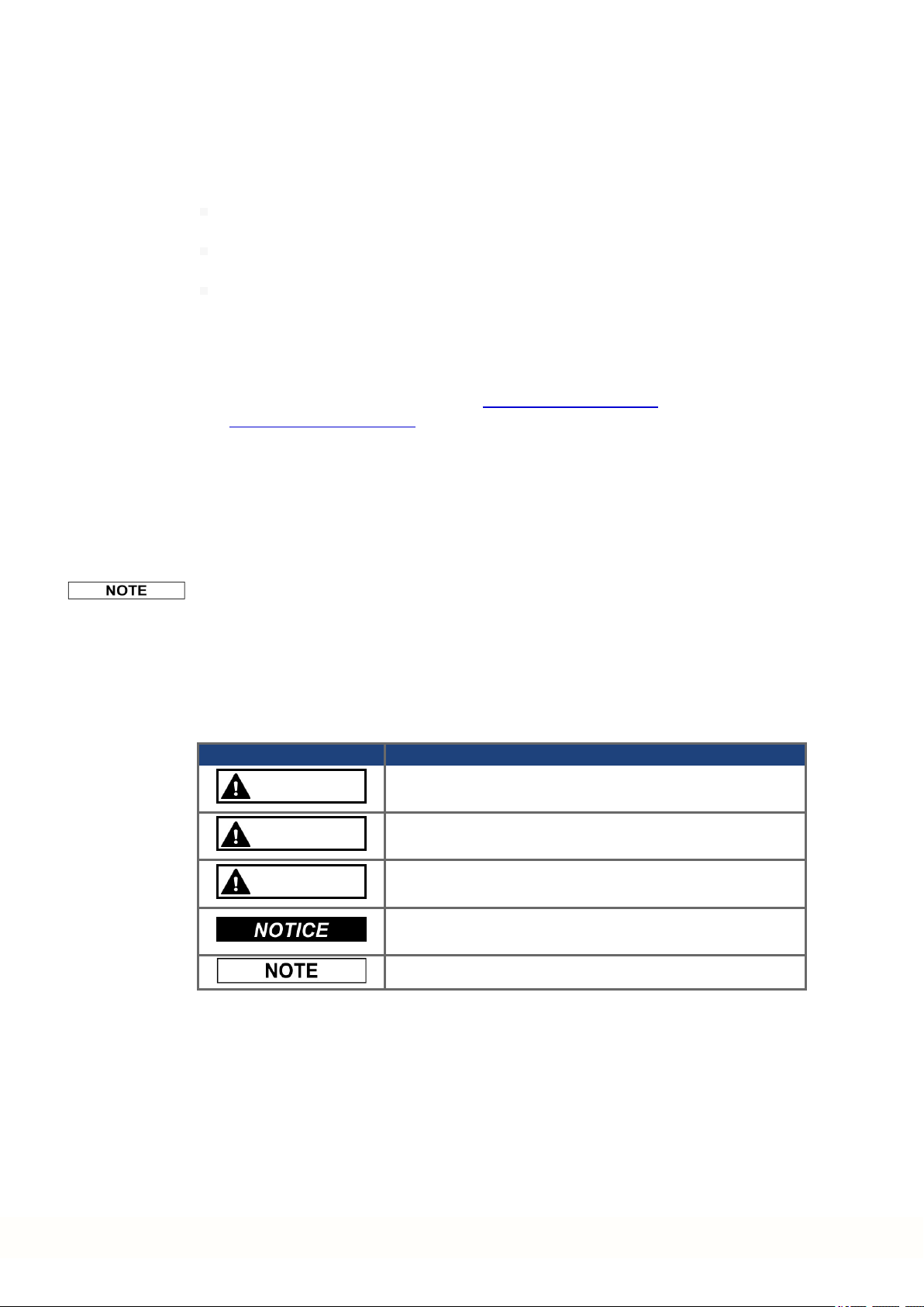
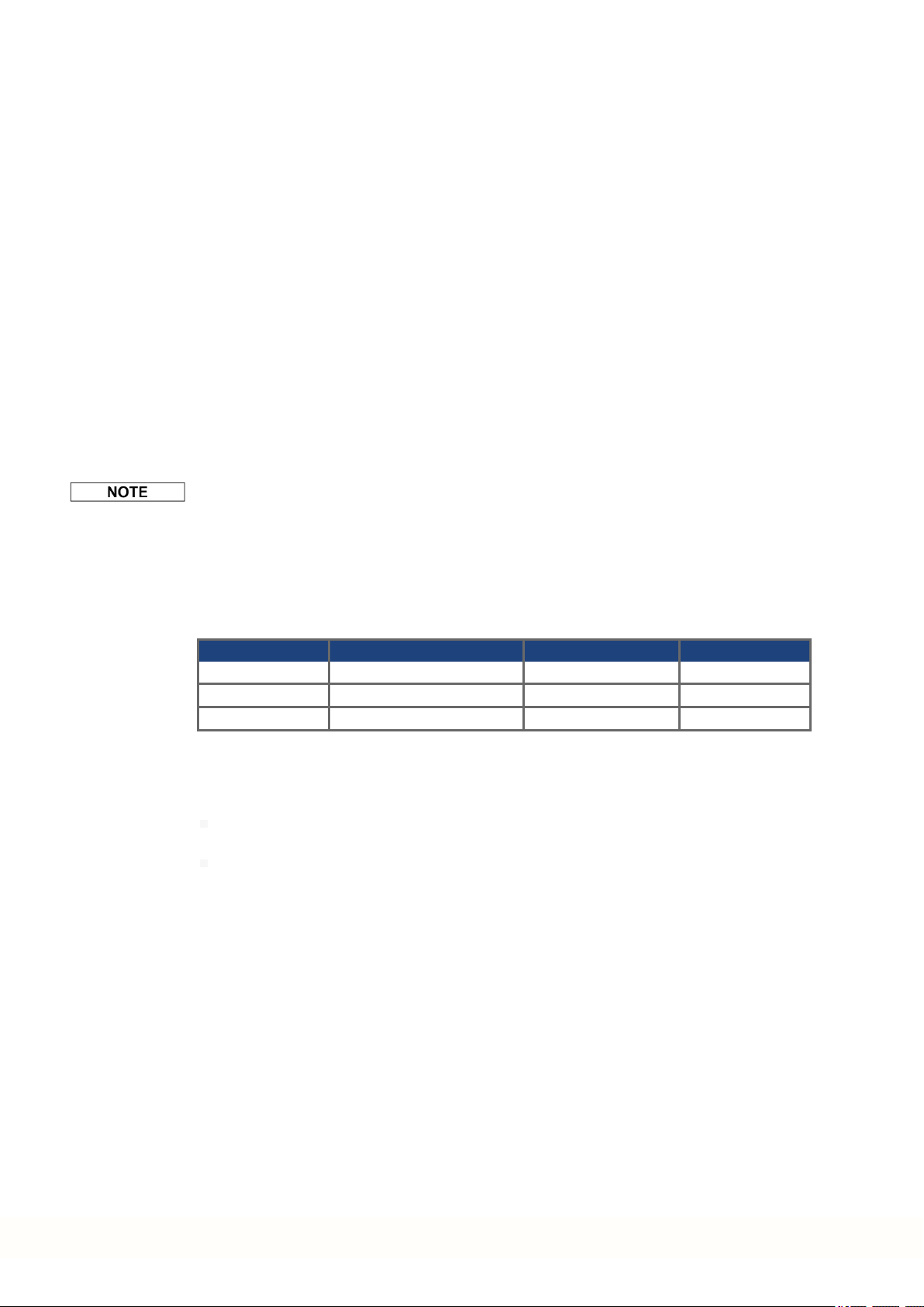
1.1.2 Symbols Used
Symbol Indication
DANGER
WARNING
CAUTION
Indicates a hazardous situation which, if not avoided, will result in death or serious injury.
Indicates a hazardous situation which, if not avoided, could
result in death or serious injury.
Indicates a hazardous situation which, if not avoided, could
result in minor or moderate injury.
Indicates situations which, if not avoided, could result in property damage.
This symbol indicates important notes.
4 Kollmorgen | kdn.kollmorgen.com | February 2018

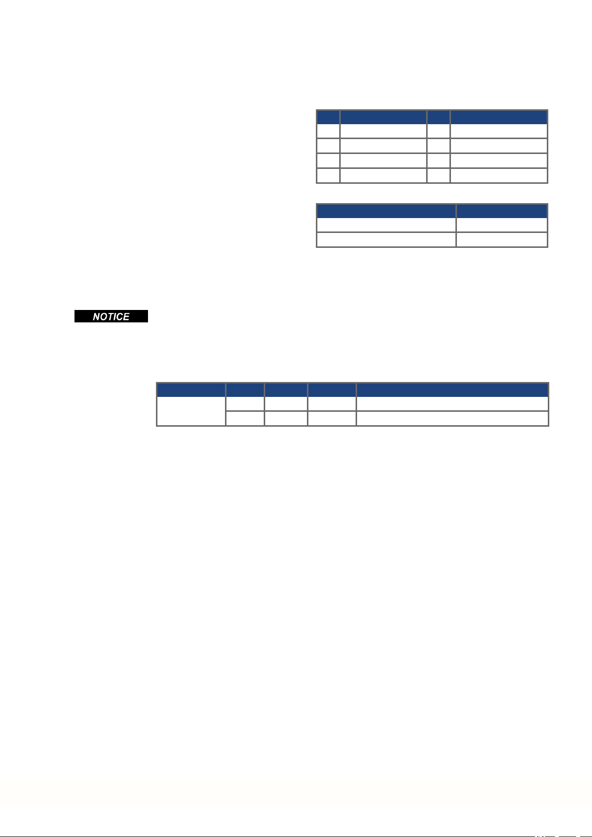
1.1.3 Abbreviations Used
Abbreviation Meaning
(➜ # 53) "see page 53" in this document
CE Communité Européenne
EMC Electromagnetic compatibility
PC Personal computer
PCMM Programmable Controller Multi-Axis Master.
PE Protective earth
RCD Residual current device
SFF Safe failure fraction
VAC Volts, alternatingcurrent
VDC Volts, direct current
1.1.4 Standards Used
Standard Content
ISO 4762 Hexagon socket head cap screws
ISO 12100 Safety of machinery: Basic concepts, general principles for design
IEC 60085 Electrical insulation - Thermal evaluation anddesignation Maintenance
IEC 60204 Safety of Machinery: Electrical equipment of machinery
IEC 60364 Low-voltage electrical installations
IEC 60439 Low-Voltage Switchgearand Controlgear Assemblies
IEC 60529 International protection rating (IP code)
IEC 60721 Classification of environmental conditions
IEC 61000 Electromagnetic compatibility (EMC)
IEC 61131 Programmable controllers
IEC 61491 Electrical equipment of industrial machines – Serial data link for real-time
IEC UL 61010-1 Safety requirements for electrical equipment for measurement, control,
IEC 82079 Preparation of instructions for use - Structuring, content andpresentation
PCMM Installation Manual | 1 English
communications betweencontrols and drives.
andlaboratory use
IEC - International Electrotechnical Commission
ISO - International Organization for Standardization
UL - Underwriters Laboratories
Kollmorgen | kdn.kollmorgen.com | February 2018 5

PCMM Installation Manual | 1 English
1.2 Safety
1.2.1 You should pay attention to this
Specialist staff required!
Only properly qualified personnel are permitted to perform such tasks as transport, assembly,
setup and maintenance. Qualifiedspecialist staff are persons who are familiarwith the transport, installation, assembly, commissioning andoperation of PCMM and who bring their relevant minimum qualifications to bear ontheirduties:
Transport: only by personnel with knowledge of handling electrostatic sensitive components.
Unpacking: only by electrically qualified personnel.
Installation: only by electrically qualified personnel.
Basic tests / Setup: only by qualified personnel with knowledge of electrical engineering
andmotion control technology
The qualifiedpersonnel must know and observe ISO 12100 / IEC 60364/ IEC 60664 and
national accident prevention regulations.
Read the documentation!
Read the availabledocumentation before installation and commissioning. Improper handling
of the device can cause harm to people ordamage to property. The operator of systems using
the PCMM must ensure that all personnel who work with the motion system read and understand the manual before using the system.
Check Hardware Revision!
Check the Hardware Revision Number of the product (see product label). This number is the
link between your product and the manual, it must match the Hardware Revision Number on
the cover page of the manual.
Pay attention to the technical data!
Adhere to the technical data and the specifications on connection conditions (rating plate and
documentation). If permissible voltagevalues or current values are exceeded, the PCMM
can be damaged.
Perform a risk assessment!
The manufacturer of the machine must generate a risk assessment for the machine, and take
appropriate measures to ensure that unforeseen movements cannot cause injury or damage
to any person or property. Additional requirements on specialist staff may also result from the
risk assessment.
Observe electrostatic sensitive components!
The PCMM contain electrostatic sensitive components which may be damaged by incorrect
handling. Electrostatic discharge yourbody before touching the PCMM. Avoid contact with
highly insulating materials (artificial fabrics, plastic film etc.). Place the PCMM on a conductive surface.
Never modify the products!
It is not allowed to modify the PCMM without permission by the manufacturer. Opening the
housing causes loss of warranty.
6 Kollmorgen | kdn.kollmorgen.com | February 2018

1.2.2 Use as Directed
PCMMs are intended for controlling Kollmorgen drives in a motion system.
PCMMs are components that arebuilt into electrical plants or machines and can only be oper-
ated as integral components of these plants or machines. The manufacturer of the machine
used with a PCMM must generate a risk assessment for the machine.
When the PCMMs are built into machines or plant, the motion system must not be used until
it has been established that the machine or plant fulfills the requirements of the regional directives.
Cabinet and wiring
PCMM must only be operated permanently connected in a closed control cabinet suitable for
the ambient conditions (➜ # 12). Ventilation or coolingmay be necessary to keep the temperature within the cabinet below 55 °C.
Use only copper conductors for wiring. The conductor cross-sections can be derived from the
standard IEC 60204 (alternatively for AWG cross-sections: NEC Table 310-16, 75 °C
column).
Power supply
The PCMM can be supplied by 24V DC industrial supply networks.
PCMM Installation Manual | 1 English
1.2.3 Prohibited Use
Otheruse than that described in chapter “Use as directed” is not intended andcan lead to personnel injuries and equipment damage. The PCMM may not be used with a machinethat
does not comply with appropriate national directives or standards. The use of the PCMM in
the following environments is also prohibited:
potentially explosive areas
environments with corrosive and/or electrically conductive acids, alkaline solutions, oils,
vapors, dusts
Kollmorgen | kdn.kollmorgen.com | February 2018 7

PCMM Installation Manual | 1 English
1.3 Handling
1.3.1 Transport
Transport the PCMM in accordance with IEC 61800-2 as follows:
Transport only by qualified personnel in the manufacturer’s original recyclable packaging.
Avoid shocks while transporting.
Store at or below maximum stacking height of 8 cartons.
Transport only within specified temperature ranges:
-25to +70 °C, max. rate of change 20 K/hour, class 2K3.
Transport only within specified humidity:
max. 95% relative humidity, no condensation, class 2K3.
The PCMM contain electro-statically sensitive components that can be damagedby incorrect handling. Electro-statically discharge yourself before touching the PCMM. Avoid contact with highly insulating materials, such as artificial fabrics and plastic films. Place the
PCMM on a conductive surface.
If the packaging is damaged, check the unit for visible damage. Inform the shipper and the
manufacturer of any damage to the package or product.
1.3.2 Packaging
The PCMM packaging consists of recyclable cardboard with inserts and a label on the outside of the box.
Packagingdimension (HxWxL): 107mm x 268mm x 220mm
Total weight: 1.2 kg
1.3.3 Storage
Store the PCMM in accordance with IEC 61800-2 as follows:
Store only in the manufacturer’s original recyclable packaging.
Store at or below maximum stacking height of 8 cartons.
Store only within specified temperatureranges: -25 to +55 °C, max.rate of change
20K/hour, class 1K4.
Storage only within specified humidity: 5 to 95% relative humidity, no condensation, class
1K3.
1.3.4 Decommissioning
Only professional staff who are qualified in electrical engineering areallowed to decommission parts of the system.
Switch off the mainswitch of the switchgear cabinet.
Securethe system against restarting.
Block the mainswitch.
8 Kollmorgen | kdn.kollmorgen.com | February 2018

1.3.5 Maintenance and cleaning
The device does not require maintenance. Opening the device voids the warranty. The inside
of the unit can only be cleaned by the manufacturer.
Do not immerse orspray the device. Avoid that liquid enters the device.
To clean the device exterior:
1. Decommission the device (see chapter 1.3.4 "Decommissioning").
2. Casing: Clean with isopropanol or similar cleaning solution.
Caution : Highly Flammable! Risk of injury by explosion and fire.
Observe the safety notes given on the cleaning liquid package.
Wait at least 30 minutes after cleaningbefore putting the device back into operation.
3. Protective grill on fan: Clean with a dry brush.
1.3.6 Disassemble
Only professional staff who are qualified in electrical engineering areallowed to disassemble
parts of the system.
1. Decommission the device (see chapter 1.3.4 "Decommissioning").
2. Remove the connectors. Disconnect the potential earth connection last.
3. Demount: loosenthe fastening screws. Remove the device.
PCMM Installation Manual | 1 English
1.3.7 System Repair
Only professional staff who are qualified in electrical engineering areallowed to exchange
parts of the drive system.
CAUTION: Automatic Start! During replacement work a combination of hazards andmul-
tiple episodes may occur.
Exchange of PCMM
Only the manufacturer can repair the device. Opening the device voids the warranty.
1. Decommission the device (see chapter 1.3.4 "Decommissioning").
2. Demount the device (see chapter 1.3.6 "Disassemble").
3. Send the device to the manufacturer.
4. Install a new device as described in this manual.
5. Setup the system as describedin this manual.
Exchange of other drive system parts
If parts of the drive system (forexample cables) must be replaced, proceedas follows:
1. Decommission the device (see chapter 1.3.4 "Decommissioning").
2. Exchange the parts.
3. Check all connections for correct fastening.
4. Setup the system as describedin this manual.
Work on the electrical installation may only be performed by trained and qualified personnel, in compliance with the regulations for safety at work, and only with use of prescribed personal safety equipment.
Kollmorgen | kdn.kollmorgen.com | February 2018 9
PCMM Installation Manual | 1 English
1.3.8 Disposal
To dispose the unit properly, contact a certified electronic scrap disposal merchant.
In accordance with the WEEE-2002/96/EC-Guidelines and similar, the manufacturer accepts
returns of old devices andaccessories for professional disposal. Transport costs are the
responsibility of the sender.
Send the devices in the original packaging to the manufacturer address:
North America South America
KOLLMORGEN
201West Rock Road
Radford, VA 24141, USA
Europe Asia
KOLLMORGEN Europe GmbH
Pempelfurtstr. 1
40880 Ratingen, Germany
KOLLMORGEN
Avenida Tamboré - 1077 Tamboré
Barueri - SP Brasil
CEP:06460-000, Brazil
KOLLMORGEN
Floor 4, Building 9, No. 518,
North Fuquan Road, Changning District,
Shanghai 200335, China
10 Kollmorgen | kdn.kollmorgen.com | February 2018
1.4 Technical description and data
1.4.1 The PCMM Motion Controller
PCMM means Programmable Controller Multi-Axis Master. The controllerIncludes programmable motion control using PLCOpen or PipeNetwork motion engines and PLC with all
5 IEC 61131 languages.
EtherCAT connects the PCMM to other components in the drive system.
1.4.2 Package Supplied
When a PCMM controller is ordered, the following items are included in the package:
PCMM
Printedcopy of PCMM Installation Manual
Mating connectors X1, X35 and X36
The mating SubD andRJ45 connectors are not included in the package.
Part Number Scheme
PCMM Installation Manual | 1 English
Kollmorgen | kdn.kollmorgen.com | February 2018 11

PCMM Installation Manual | 1 English
1.4.3 Technical Data
Rated Data
Electrical Data Units PCMM
Rated supply voltage V DC 24 V ±10% see (➜ # 133)
Rated input current A 1.25
Rated input power W 30
Permitted switch on/off frequency 1/h 30
Mechanical data
Weight kg 0.45
Dimensions (HxWxD) mm 174 x 50 x 111.5 see (➜ # 130)
Dimensions (HxWxD) with connectors mm 208x 50 x 147.5 see (➜ # 130)
Recommended Tightening Torques
X1, X35, X36 Nm (in-lbf) 0.2 to 0.25 (2)
PE block Nm (in-lbf) 1.7 (15)
Fusing
Circuit Max.
Ampere rating
24 V DC supply 8A (Time-Delay) LPJ8SP/DFJ8 AJT8
Inputs/Outputs
Interface Electrical Data
Digital inputs
see (➜ # 135)
Digital outputs
see (➜ # 136)
Ambient Conditions, Ventilation, and Mounting Position
Storage, Transport (➜ # 8)
Ambient temperature
in operation
Humidity
in operation
Site altitude Up to 2500 meters above meansea level without restriction
Pollution level Pollution level 2 as per IEC 61010-1
Vibrations Class 3M1 according to IEC 60721-3-3
Enclosure protection IP 20 accordingto IEC 60529
Mounting position Vertical
Ventilation Free convection
ON: 3.5 VDC to 30 VDC, 2 mA to 15 mA
OFF: -2 VDC to 2 VDC, max.15 mA
Galvanic isolation for 250 VDC
Update rate: Software 250µs
Source or Sink type
Max. 30 VDC, 100 mA
Short circuit proof
Galvanic isolation for 250 VDC
Update rate: 1 ms
Active low or active high
0 to +55° C under rated conditions
Relative humidity 5 to 85%, no condensation, class 3K3
according to IEC 60721-3-3
Example class J
Cooper Bussmann
Example class J
Ferraz Shawmut
12 Kollmorgen | kdn.kollmorgen.com | February 2018

1.5 Mechanical Installation
Dimensions overview see (➜ # 130).
1.5.1 Important Notes
Protect the PCMM from impermissible stresses. In particular, do not let any components
become bent or any insulation distances altered during transport and handling. Avoid contact
with electronic components and contacts.
The PCMM will switch itself off in case of overheating. Ensure that there is an adequate flow
of cool, filtered air into the bottom of the control cabinet, or use a heat exchanger.
Do not mount devices that produce magnetic fields directly beside the PCMM. Strong magnetic fields can directly affect internal components. Install devices which produce magnetic
field with distance to the PCMM and/or shield the magnetic fields.
1.5.2 Guide to Mechanical Installation
The following tools are required (at a minimum) to install the PCMM; your specific installation
may requireadditional tools:
M4 hexagonsocket-cap screws (ISO 4762)
3 mm T-handle Allen key
No. 2 Phillips head screwdriver
Small slotted screwdriver
PCMM Installation Manual | 1 English
Install the PCMM unit as follows:
1. Prepare the site.
Mount the PCMM in a closed control cabinet. The site must be free from conductive or corrosive materials.
2. Check ventilation.
Check that the ventilation of the PCMM is unimpeded, and keep within the permitted ambient temperature (➜ # 12). Keep therequired space clearance above and below the
PCMM.
3. Check coolingsystem.
If cooling systems are used for the control cabinet, position the coolingsystem so that
condensation water cannot drip onto the PCMM or peripheral devices.
4. Mount the PCMM.
Assemble the PCMM and power supply near each other on the conductive, grounded
mounting plate in the cabinet.
5. Ground the PCMM.
Ground the mounting plate, PCMM housing and CNC-GND of the control system.
Kollmorgen | kdn.kollmorgen.com | February 2018 13

PCMM Installation Manual | 1 English
1.6 Electrical Installation
For connector overview and I/O connection (➜ # 131).
1.6.1 Important Notes
Only professional staff who are qualified in electrical engineering areallowed to install the
controller. Wires with color green with one ormore yellow stripes must not be used other
than for protective earth (PE) wiring.
Excessively high external fusing will endanger cables and devices. The fusing of the 24V
supply must be installed by the user, best values (➜ # 12).
It is permissible to use the setup software (KAS IDE) to alter the device settings. Any other
alterations will invalidate the warranty.
1.6.2 Guide to electrical installation
Install the PCMM electrical system as follows:
1. Select cables in accordance with IEC 60204 .
2. Install shielding and ground the PCMM.
Ground the mounting plate and CNC-GND of the control system.
3. Connect all interfaces according to the wiring diagrams in (➜ # 131).
14 Kollmorgen | kdn.kollmorgen.com | February 2018

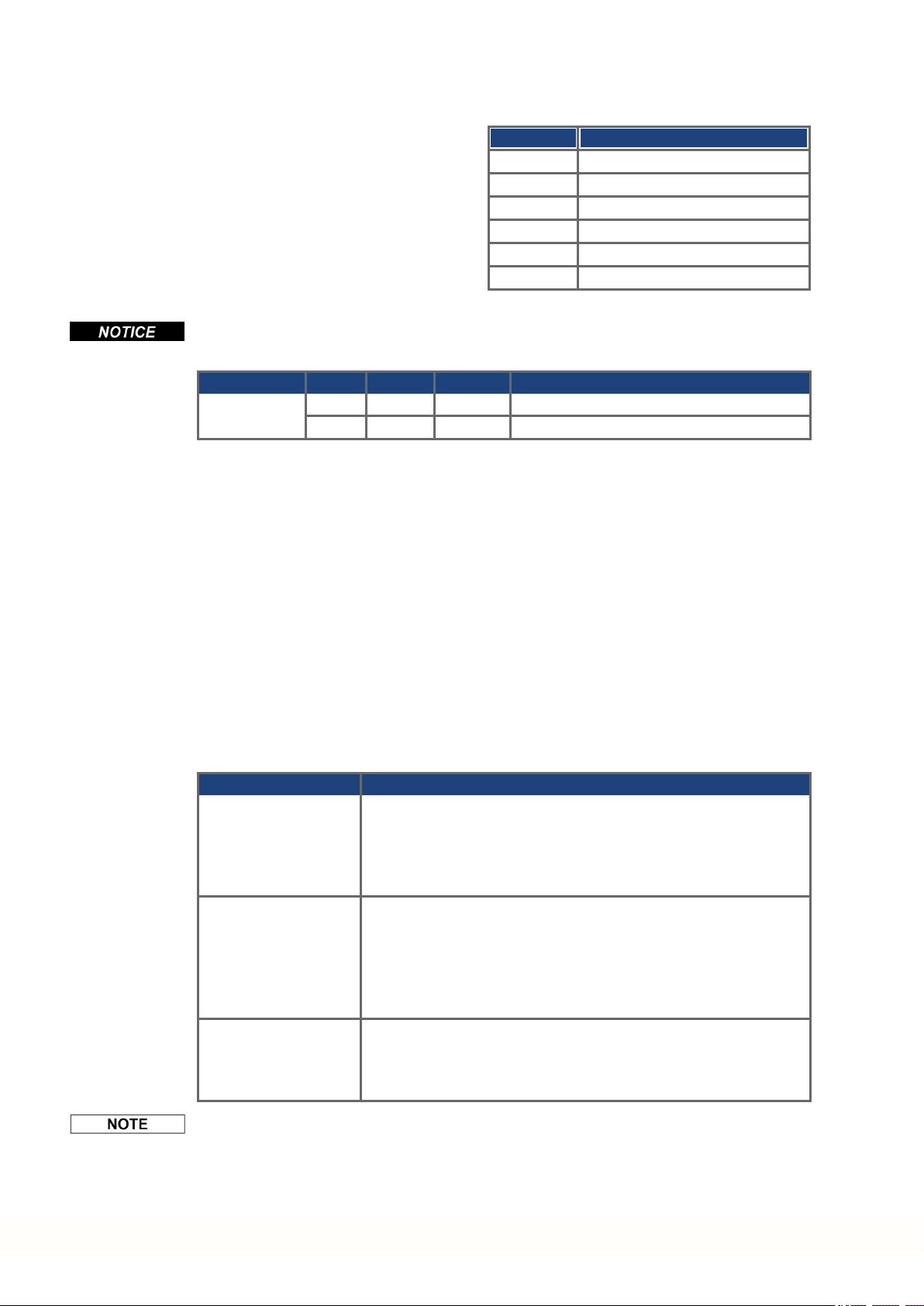
1.6.3 Push-buttons (B2, B3)
The push-buttons can beused to start predefined functions.
Function Push-button Remarks
Boot-time functions (press and hold button during power-on boot sequence)
Recovery
Mode
Menu B3 Press and hold to block the application auto-start andto start
Operational functions (press button during normal operation mode)
Menu B3 Press to cycle through the menu items. The menuitems will dis-
Select Menu
Item
PCMM Installation Manual | 1 English
B2 Press and hold to boot into recovery mode.
cycling through the menu items.
playedon the 7-segment LED repeatedly for 10 s and can be
selected py pressing B2.
B2 Press while the required menu item is displayed to perform
action.
Application is running, available menu items:
'IP' address
'stop' application (confirm)
No application is running, available menu items:
'IP' address
'start' application (confirm)
'reset' to defaults (confirm)
'backup' to SD card (confirm)
'restore' from SD card (confirm)
Confirm B2 If the selected menu item selection requires a confirmation, "y"
is displayed for 10 s - press B2 to confirm.
Kollmorgen | kdn.kollmorgen.com | February 2018 15
PCMM Installation Manual | 1 English
1.6.4 SD Card Slot
PCMM offers a SD card slot and push-buttons B2 and B3 to activate file transfers from/to the
PCMM and SD Memory Card. These features can be started from the KAS IDE software as
well. Detailled description can be found in the KAS Online Help.
The backup/restore operations (PCMM to SD or SD to PCMM) will not be possible if an
application is running.
Stop the application from the web-browser or use the B2/B3 “stop”action beforeinitiating
any SD card functionality.
If a fault occurs during save/load operations, the fault number is displayed in the one digit display with E followed by two digits. Error codes (➜ # 137) .
Supported SD card types
SD cards are preformatted by the manufacturer. The following table outlines the SD card
types and PCMM support.
SD Type File System Capacity Supported
SD (SDSC) FAT16 1MB to 2GB YES
SDHC FAT32 4GB to 32GB YES
SDXC exFAT (Microsoft) >32GB to 2TB NO
Features
If an SD card is plugged into the SD slot andno application programm is running, the pushbutton menu (started with B3) shows the possible data transfer functions:
'backup' to copy firmware, configurations, user application, and user data files from the
PCMM to SD card.
'restore' to load firmware, configuration, user application, and user data files from SD card
to PCMM.
16 Kollmorgen | kdn.kollmorgen.com | February 2018
1.6.5 Service Interface (X32)
Operating, position control, and motion-block parameters can be set up by using the setup
software on anordinary commercial PC.
Connect the service interface (X32) of the PCMM to an Ethernet interface on the PC directly
or via a network hub/switch, while the supply to the equipment is switched off. Use
standard Cat. 5 Ethernet cables for connection (in some cases crossover cables will also
work).
Do not connect the motionbus cableto the service interface X32. The motion bus cable
must be connected to X6.
PCMM Installation Manual | 1 English
Pin Signal Pin Signal
1 Transmit + 5 n.c.
2 Transmit - 6 Receive3 Receive+ 7 n.c.
4 n.c. 8 n.c.
Protocol Type
Modbus TCP Service Bus
Ethernet TCP/IP Service Bus
Confirm that the link LED on the PCMM (the green LED on the RJ45 connector) and on your
PC (or network Hub/Switch) are both illuminated. If both lights are illuminated, then you have
a good electrical connection.
Connector LED# Color Name Indication
X32 LED1 Green Link On = receive signal valid
LED2 Yellow Activity Blink = Transmit or Receive packet
Possible Network Configurations
Kollmorgen | kdn.kollmorgen.com | February 2018 17
PCMM Installation Manual | 1 English
1.6.6 Motion Bus Interface (X6)
Do not connect the Ethernet service cable for the PC to the motion bus interface X6. The Ethernet service cable must be connected to X32.
Connector LED# Color Name Indication
X6 LED3 Green Link On = receive signal valid
1.6.7 Rotary Switch (RS1)
You can use the rotary switch RS1 to set the IP address of the PCMM. The configured IP
address (depending on the current rotary switch RS1 position) will be displayed onthe 7 segment at Ethernet cable connection time and at power-on, if an Ethernet cable is connected. If
no Ethernet cable is connected, no IP address will be indicated in the display.
Pin Signal
1 Receive+
2 Receive3 Transmit +
4, 5 n.c.
6 Transmit -
7, 8 n.c.
LED4 Yellow Activity Blink = Transmit or Receive packet
Rotary Switch Setting PCMM IP Address
0 DHCP/AutoIP address. The IP address of the device is obtained
from the DHCP server onyournetwork. If no DHCP server is
found the IP addresses is an AutoIP address (it is internally generated followingthe AutoIP protocol andwill be of the form
169.254.xx.xx).
1 Static IP Address. The IP address is software configurablefrom a
web-browser. The default IP address at switch position 1 is
192.168.1.101. To configure the IP address, open a web browser
andtype the IP address in the URL box. The PCMM web page will
appear. Navigate to the Settings tab and then the Network tab to
configure the static IP address for the PCMM.
2 to 9 Static IP Address. The IP address is 192.168.0.10n, where n is the
numberfrom the rotary switch. This setting generates addresses in
a range from 192.168.0.102 to 192.168.0.109. Example:if RS1 is
set to 5 – the IP address is 192.168.0.105
The PC subnet mask must be set to 255.255.255.0 or 255.255.255.128
18 Kollmorgen | kdn.kollmorgen.com | February 2018

PCMM Installation Manual | 1 English
Static IP addressing
When connecting the PCMM directly to a PC, static IP addressing must be used. Set rotary
switch RS1 to a number from 2 to 9 (see table above)
Dynamic IP addressing (DHCP and Auto-IP)
With RS1 set to 0, the PCMM is in DHCP mode. The PCMM will acquire its IP address from
an external DHCP server if present in the network. If a DHCP server is not present, the
device will assume an Automatic Private IP Address of the form 169.254.x.x.
If your PC is directly connected to the device, and set to obtain anIP address automatically
in the TCP/IP settings, a connection will be established with both devices using compatible
automatic generated addresses. It can take up to 60 seconds for a PC to configure an Automatic Private IP Address (169.254.x.x).
Changing the IP address
If the switch is altered while 24V Logic power is supplied to the PCMM, you must switch off
andthenswitch on again the 24 V supply voltage. This action will reset the address.
Kollmorgen | kdn.kollmorgen.com | February 2018 19
PCMM Installation Manual | 1 English
1.7 Setup
1.7.1 Important Notes
Beforetesting and setup, the manufacturer of the machine must generate a risk assessment
for the machine and take appropriate measures so that unforeseenmovements cannot
cause injury or damageto any person orproperty.
Only professional personnel with extensive knowledge in the fields of electrical engineering
anddrive technology are allowed to test and set up the device.
Sets of data that have been stored on data media arenot safe against unintended alteration
by other persons. Unexpected move couldbe the result if you use unchecked data. After
loading a set of data you must therefore always check all parameters beforeenabling the
device.
1.7.2 Setup with KAS IDE
The controller anddrives must be adapted to the requirements of your machine. For most
applications, you can use a PC and KAS IDE software ("Kollmorgen Automation Suite Integrated development environment) to set up the operating conditions and parameters for your
motion system. The PC is connected to the PCMM by an Ethernet cable.
The KAS IDE integrated development environment contains tools for configuring the EtherCAT Network, setup and tuning Kollmorgen drives, creating a PLC program, and creating an
HMI.
The KAS IDE is available by DVD or electronic delivery. Please contact your Kollmorgen
sales representative for information. The PCMM Runtime is available from the KDN
(http://kdn.kollmorgen.com) or Kollmorgen Website (http://www.kollmorgen.com).
Kollmorgen offers training and familiarization courses.
See "KAS getting started" guide for proceedingwith setup.
1.8 Troubleshooting the PCMM
Motion Controller problems occur for a variety of reasons, depending on the conditions in your
installation. The causes of faults in multi-axis systems can be especially complex. If you cannot resolve a fault or otherissue using the troubleshooting guidance presented below, customer support can give you further assistance.
The most commonfaults are listed in Chapter "Fault and Warning Messages" (➜ # 137).
More details on the removal of faults can be found in the online help.
20 Kollmorgen | kdn.kollmorgen.com | February 2018

PCMM Installation Manual | 2 Deutsch
2 Deutsch
2.1 Allgemeines 22
2.1.1 Hinweise für die gedruckte Ausgabe (Papierversion) 22
2.1.2 Verwendete Symbole 22
2.1.3 Verwendete Abkürzungen 23
2.1.4 Verwendete Normen 23
2.2 Sicherheit 24
2.2.1 Das sollten Sie beachten 24
2.2.2 Bestimmungsgemäße Verwendung 25
2.2.3 Nicht bestimmungsgemäße Verwendung 25
2.3 Handhabung 26
2.3.1 Transport 26
2.3.2 Verpackung 26
2.3.3 Lagerung 26
2.3.4 Außer Betrieb nehmen 26
2.3.5 Wartung und Reinigung 27
2.3.6 Demontage 27
2.3.7 System Reparatur 27
2.3.8 Entsorgung 28
2.4 Technische Beschreibung und Daten 29
2.4.1 Der PCMM Motion Controller 29
2.4.2 Lieferumfang 29
2.4.3 Technische Daten 30
2.5 Mechanische Installation 31
2.5.1 Wichtige Hinweise 31
2.5.2 Leitfaden zurmechanischen Installation 31
2.6 Elektrische Installation 32
2.6.1 Wichtige Hinweise 32
2.6.2 Leitfaden fürdie elektrische Installation 32
2.6.3 Taster (B2, B3) 33
2.6.4 SD-Speicherkarte 34
2.6.5 Serviceschnittstelle (X32) 35
2.6.6 Motion-Bus-Schnittstelle (X6) 36
2.6.7 Drehschalter (RS1) 36
2.7 Inbetriebnahme 38
2.7.1 Wichtige Hinweise 38
2.7.2 Inbetriebnahme mit KAS IDE 38
2.8 Fehlersuche und -behebung beim PCMM 38
Kollmorgen | kdn.kollmorgen.com | February 2018 21
PCMM Installation Manual | 2 Deutsch
2.1 Allgemeines
Dieses Handbuch, der PCMM Installation Manual, beschreibt die sichere Installation und
Inbetriebnahme des PCMM Motion Controllers.
WeiterführendeDokumente:
EtherCAT-Kommunikation (PDF-Format):
Beschreibt, wie Sie Ihren Controller in EtherCAT-Anwendungenverwenden.
Ethernet/IP-Kommunikation: Beschreibt, wie Sie Ihren Controllerin Ethernet/IP-Anwendungen verwenden.
KAS Onlinehilfe (WebHelp-Format):
Beschreibt, wie Sie Ihren Controller in allgemeinen Anwendungen verwenden. Die Onlinehilfe bietet Ihnen auch Tipps für die Inbetriebnahme und zur Optimierung der Systemleistung. Die Onlinehilfe umfasst das Referenzhandbuch für Parameter und Befehle
mit Informationen zu den Parametern und Befehlen, die für die Programmierung des
Antriebssystems verwendet werden.
Alle Dokumente sind überdas KDN (http://kdn.kollmorgen.com) oder die Kollmorgen Web-
site (http://www.kollmorgen.com) erhältlich.
2.1.1 Hinweise für die gedruckte Ausgabe (Papierversion)
Jedem Produkt liegt eine gedruckte Ausgabe dieses Handbuchs
bei. Aus ökologischen Gründen wurde das Dokument verkleinert
auf DIN A5 gedruckt.
Sollten Sie Schwierigkeiten haben, die Schriftgröße des verkleinert
gedruckten Exemplars zu lesen, können Sie die PDF Version im
DIN A4 Format 1:1 ausdrucken und verwenden. Sie finden die
PDF Version auf der dem Produkt beiliegenden DVD und auf der
Kollmorgen Internetseite.
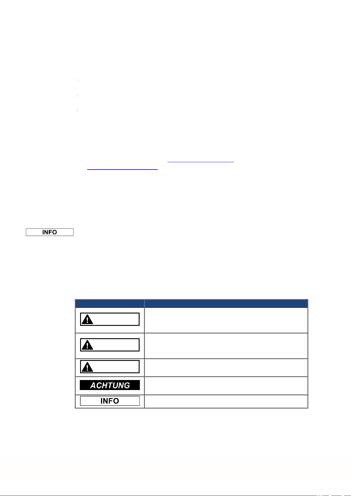
2.1.2 Verwendete Symbole
Symbol Bedeutung
GEFAHR
WARNUNG
VORSICHT
Weist auf einegefährliche Situation hin, die, wenn sie nicht vermieden wird, zum Todeoder zu schweren, irreversiblen Verletzungen führenwird.
Weist auf einegefährliche Situation hin, die, wenn sie nicht vermieden wird, zum Todeoder zu schweren, irreversiblen Verletzungen führenkann.
Weist auf einegefährliche Situation hin, die, wenn sie nicht vermieden wird, zu leichten Verletzungen führenkann.
Dieses Symbol weist auf eine Situation hin, die, wenn sie nicht
vermiedenwird, zu Beschädigungvon Sachen führen kann.
Dieses Symbol weist auf wichtige Informationen hin.
22 Kollmorgen | kdn.kollmorgen.com | February 2018

2.1.3 Verwendete Abkürzungen
Abkürzung Bedeutung
(➜ # 53) „siehe Seite 53“indiesem Dokument
CE Europäische Gemeinschaft
EMV Elektromagnetische Verträglichkeit
PC Personal Computer
PCMM Programmable Controller Multi-Axis Master.
PE Schutzerde
RCD Fehlerstromschutzschalter (FI-Schalter)
SFF Anteil sicherer Ausfälle
VAC Volt, Wechselspannung
V DC Volt, Gleichspannung
2.1.4 Verwendete Normen
Norm Inhalt
EN 4762 Zylinderschrauben mit Innensechskant
EN12100 Sicherheit von Maschinen: Grundbegriffe, allgemeine Gestal-
EN 60085 Elektrische Isolierung – Thermische Bewertung und Bezeichnung
EN60204 Sicherheit von Maschinen: Elektrische Ausrüstung von Maschinen
IEC60364 Errichten von Niederspannungsanlagen
EN60439 Niederspannungs-Schaltgerätekombinationen
EN60529 Schutzarten durch Gehäuse (IP-Code)
EN60721 Klassifizierung von Umweltbedingungen
EN61000 Elektromagnetische Verträglichkeit (EMV)
EN61131 Speicherprogrammierbare Steuerungen
EN61491 Ausrüstung von Industriemaschinen – Serielle Datenverbindung für Echt-
IEC UL 61010-1 Sicherheitsbestimmungen für elektrische Mess-, Steuer-, Regel- und
EN82079 Erstellen von Anleitungen – Gliederung, Inhalt und Darstellung
PCMM Installation Manual | 2 Deutsch
tungsleitsätze
zeit-Kommunikation zwischen Steuerungen undAntrieben.
Laborgeräte
IEC – International Electrotechnical Commission
ISO – International Organization forStandardization
UL – Underwriters Laboratories
Kollmorgen | kdn.kollmorgen.com | February 2018 23

PCMM Installation Manual | 2 Deutsch
2.2 Sicherheit
2.2.1 Das sollten Sie beachten
Fachpersonal erforderlich
Nur qualifiziertes Fachpersonal darf Arbeiten wie Transport, Montage, Inbetriebnahme und
Instandhaltung ausführen. Qualifiziertes Fachpersonal sind Personen, die mit Transport, Aufstellung, Montage, Inbetriebnahme und Betriebdes PCMM vertraut sind und über die erforderlichen Mindestqualifikationen fürihre Aufgabe verfügen:
Transport: nur durch Personal mit Kenntnissen in der Behandlung elektrostatisch gefährdeter Bauelemente
Auspacken: nur durch Fachleute mit elektrotechnischer Ausbildung
Installation: nurdurch Fachleute mit elektrotechnischer Ausbildung
Einrichtung/Inbetriebnahme: nur durch Fachleute mit weitreichenden Kenntnissen in den
Bereichen Elektrotechnik/Antriebstechnik
Das Fachpersonal muss ebenfalls die ISO12100/ IEC 60364 / IEC 60664und nationale
Unfallverhütungsvorschriften kennenund beachten.
Dokumentation lesen
Lesen Sie vor der Montage und Inbetriebnahmedie vorliegende Dokumentation. Falsches
Handhaben des Gerätes kann zu Personen- oder Sachschäden führen. Der Betreiber muss
daher sicherstellen, dass alle mit Arbeiten am PCMM betrauten Personen das Handbuch vor
Verwendung des Systems gelesen und verstanden haben.
Hardware-Revision prüfen
PrüfenSie die Hardware-Revisionsnummer des Produkts (siehe Typenschild). Diese Nummer ordnet Ihr Produkt dem Handbuch zu und muss mit derHardware-Revisionsnummerauf
derTitelseite des Handbuchs übereinstimmen.
Technische Daten beachten
Beachten Sie die technischenDaten und die Angaben zu den Anschlussbedingungen (Typenschild und Dokumentation). Wenn zulässige Spannungswerte oder Stromwerte überschritten
werden, kann der PCMM beschädigt werden.
Risikobeurteilung durchführen
Der Maschinenhersteller muss eine Risikobeurteilung für die Maschineerstellen und geeignete Maßnahmen dafür treffen, dass unvorhergesehene Bewegungen nicht zu Sach- oder
Personenschäden führen können. Aus der Risikobeurteilung leiten sich eventuell auch
zusätzliche Anforderungen andas Fachpersonal ab.
Elektrostatisch empfindliche Bauteile
Die PCMMs enthalten elektrostatisch gefährdete Bauelemente, die durch unsachgemäße
Behandlungbeschädigt werden können. Entladen Sie Ihren Körper, bevor Sie den PCMM
berühren. VermeidenSie den Kontakt mit hochisolierenden Stoffen (Kunstfaser, Kunststofffolien usw.). Legen Sie den PCMM auf eine leitfähige Unterlage.
Geräte nicht verändern
Veränderungen am PCMM ohne Genehmigungdes Herstellers sind nicht zulässig. Durch Öffnender Geräte erlischt die Gewährleistung.
24 Kollmorgen | kdn.kollmorgen.com | February 2018

2.2.2 Bestimmungsgemäße Verwendung
PCMMs werden zur Steuerung von Kollmorgen Servoverstärkern in einem Servoantriebssystem verwendet.
PCMMs werden als Komponenten in elektrische Anlagen oder Maschinen eingebaut und dürfen nur als integrierte Komponenten der Anlage in Betriebgenommen werden. Der Hersteller
dermit dem PCMM verwendeten Maschine muss eine Risikobeurteilung für die Maschine
erstellen undgeeignete Maßnahmen dafürtreffen, dass unvorhergesehene Bewegungen
nicht zu Sach- oder Personenschäden führen können.
Wenn PCMMs in Maschinen oder Anlagen eingebaut werden, darf das Antriebssystem nicht
verwendet werden, bis sichergestellt wurde, dass die Maschine oderAnlage dieAnforderungen dergeltenden Richtlinien erfüllt.
Einbau und Verdrahtung
Sie dürfen PCMMs nur fest angeschlossen im geschlossenen Schaltschrank unter geeigneten Umgebungsbedingungen betreiben (➜ # 30). Um die Temperatur im Schaltschrank
unter 55°C zu halten, kannBelüftung oder Kühlung erforderlich sein.
Verwenden Sie für die Verdrahtung ausschließlich Kupferleiter. Der Leiterquerschnitt kann
von der Norm EN 60204abgeleitet werden (alternativ für AWG-Leiterquerschnitte: NECTabelle 310-16, Spalte 75 °C).
PCMM Installation Manual | 2 Deutsch
Spannungsversorgung
Der PCMM kannan 24-V-Gleichstrom-Industrienetzen angeschlossen werden.
2.2.3 Nicht bestimmungsgemäße Verwendung
Eine andere Verwendung als in Kapitel „Bestimmungsgemäße Verwendung“beschrieben ist
nicht bestimmungsgemäß und kann zu Schäden bei Personen, Gerät oder Sachen führen.
Der PCMM darf nicht mit Maschinen betrieben werden, die nicht den geltenden nationalen
Richtlinien oder Normen entsprechen. Der Betrieb des PCMM in folgenden Umgebungen ist
verboten:
explosionsgefährdete Bereiche
Umgebungen mit korrosiven und/oder elektrisch leitenden Säuren, Alkali-Lösungen, Ölen,
Dämpfen und Staub
Kollmorgen | kdn.kollmorgen.com | February 2018 25
PCMM Installation Manual | 2 Deutsch
2.3 Handhabung
2.3.1 Transport
Transportieren Sie den PCMM gemäß EN61800-2 wie folgt:
Transport nur in der recycelbaren Originalverpackungdes Herstellers durch qualifiziertes
Personal. Beim Transport Stöße vermeiden.
Höchstens mit dermaximalen Stapelhöhe (8Kartons) stapeln.
Temperatur beim Transport:
-25bis +70 °C, max. Änderungsrate 20K/Stunde, Klasse2K3.
Feuchtigkeit beim Transport:
max. 95% relative Luftfeuchtigkeit, ohne Betauung, Klasse2K3.
Die PCMM enthalten elektrostatisch gefährdete Bauelemente, die durch unsachgemäße
Behandlungbeschädigt werden können. Entladen Sie Ihren Körper, bevor Sie den PCMM
berühren. VermeidenSie den Kontakt mit hochisolierenden Stoffen (Kunstfaser, Kunststofffolien usw.). Legen Sie den PCMM auf eine leitfähige Unterlage.
Wenn dieVerpackung beschädigt ist, prüfen Sie das Gerät auf sichtbareSchäden. Informieren Sie den Spediteur und denHerstellerüber jegliche Schäden an der Verpackung oder
am Produkt.
2.3.2 Verpackung
Die Verpackung des PCMM besteht aus recycelbarem Karton mit Einlagen undeinem Aufkleberauf der Außenseite.
Verpackungsmaße (HxBxT): 107mm x 268mm x 220mm
Gesamtgewicht: 1,2kg
2.3.3 Lagerung
Lagern Sie denPCMM gemäß EN61800-2 wie folgt:
Lagerung nurin der recycelbaren Originalverpackung des Herstellers.
Höchstens mit dermaximalen Stapelhöhe (8Kartons) stapeln.
Temperatur bei Lagerung: -25 bis +55 °C, max. Änderungsrate 20K/Stunde, Klasse1K4.
Feuchtigkeit bei Lagerung: 5 bis 95% relative Luftfeuchtigkeit, ohneBetauung,
Klasse1K3.
2.3.4 Außer Betrieb nehmen
Nur Fachpersonal mit Kenntnissen im Bereich der Elektrotechnik darf Systemkomponenten
außer Betrieb nehmen.
Schalten Sie den Hauptschalter des Schaltschranks aus.
SichernSie das System gegenWiedereinschalten.
BlockierenSie den Hauptschalter.
26 Kollmorgen | kdn.kollmorgen.com | February 2018
2.3.5 Wartung und Reinigung
Das Gerät ist wartungsfrei. Wenn das Gerät geöffnet wird, erlischt die Garantie. Das Innere
des Geräts kann nur vom Hersteller gereinigt werden.
Das Gerät nicht in Flüssigkeiten tauchen oder besprühen. Vermeiden Sie, dass Flüssigkeit
in das Gerät eindringt
So reinigen Sie das Gerät von außen:
1. NehmenSie das Gerät außerBetrieb (siehe Kapitel 2.3.4 "Außer Betrieb nehmen").
2. Gehäuse: Mit Isopropanol odereiner ähnlichen Reinigungslösung reinigen.
VORSICHT : Leicht Entflammbar! Gefahrvon Verletzung durch Verpuffung undFeuer.
Beachten Sie die Sicherheitshinweise auf der Verpackung des Reinigungsmittels.
Warten Sie nach der Reinigungmindestens 30 Minuten, bevor Sie das Gerät wiederin Betrieb nehmen.
3. Schutzgitter am Lüfter: Mit einer trockenen Bürste reinigen.
2.3.6 Demontage
Nur Fachpersonal mit Kenntnissen im Bereich der Elektrotechnik darf Systemkomponenten
demontieren.
PCMM Installation Manual | 2 Deutsch
1. NehmenSie das Gerät außerBetrieb (siehe Kapitel 2.3.4 "Außer Betrieb nehmen").
2. EntfernenSie die Stecker. Trennen Sie den PE Anschluss zuletzt.
3. Ausbauen: Lösen Sie die Befestigungsschrauben und entfernen Sie das Gerät.
2.3.7 System Reparatur
Nur Fachpersonal mit Kenntnissen im Bereich der Elektrotechnik darf Systemkomponenten
austauschen.
VORSICHT: Unerwarteter Anlauf! Bei der Durchführungvon Austauscharbeiten kannes
zur Kombinationvon Gefährdungen und multiplen Folgen kommen.
Arbeiten sind nur unter Beachtung der Vorschriften für Arbeitssicherheit, durch geschultes Personal und mit Benutzung derjeweils vorgeschriebenen persönlichen Schutzausrüstung zulässig.
Austausch PCMM
Nur derHersteller kann das Gerät reparieren. Öffnen des Gerätes bedeutet Verlust der
Gewährleistung.
1. NehmenSie das Gerät außerBetrieb (siehe Kapitel 2.3.4 "Außer Betrieb nehmen").
2. Demontieren Sie das Gerät (siehe Kapitel 2.3.6 "Demontage").
3. Senden Sie das Gerät an den Hersteller.
4. Installieren Sie einneues Gerät wie in diesem Handbuch beschrieben.
5. Nehmen Sie das System in Betrieb, wie in diesem Handbuch beschrieben.
Austausch sonstiger Teile des Antriebssystems
Wenn Teile des Antriebssystems ausgetauscht werden müssen (zum Beispiel Kabel), gehen
Sie wie folgt vor:
1. NehmenSie das Gerät außerBetrieb (siehe Kapitel 2.3.4 "Außer Betrieb nehmen").
2. Tauschen Sie dieTeile aus.
3. Prüfen Sie alle Steckverbindungen auf korrekten Sitz.
4. Nehmen Sie das System in Betrieb, wie in diesem Handbuch beschrieben.
Kollmorgen | kdn.kollmorgen.com | February 2018 27

PCMM Installation Manual | 2 Deutsch
2.3.8 Entsorgung
Für die fachgerechte Entsorgung des Gerätes wendenSie sich an einen zertifizierten Elektronikschrottverwerter.
Gemäß denWEEE-2002/96/EG-Richtlinien u.ä. nimmt der HerstellerAltgeräte und Zubehör
zur fachgerechten Entsorgung zurück. Die Transportkosten muss der Versender tragen.
Senden Sie dieGeräte in der Originalverpackung an die in der folgenden Tabelle aufgeführten
Herstelleradressen.
Nordamerika Südamerika
KOLLMORGEN
201West Rock Road
Radford, VA 24141, USA
Europa Asien
KOLLMORGEN Europe GmbH
Pempelfurtstr. 1
40880 Ratingen, Germany
KOLLMORGEN
Avenida Tamboré - 1077 Tamboré
Barueri - SP Brasil
CEP:06460-000, Brazil
KOLLMORGEN
Floor 4, Building 9, No. 518,
North Fuquan Road, Changning District,
Shanghai 200335, China
28 Kollmorgen | kdn.kollmorgen.com | February 2018

2.4 Technische Beschreibung und Daten
2.4.1 Der PCMM Motion Controller
PCMM steht für Programmable Controller Multi-Axis Master (programmierbare zentrale Mehrachssteuerung). Der Controller bietet eine programmierbare Antriebssteuerung über die
PLCOpen- oderPipeNetwork-Software und SPS mit allen fünf IEC61131-Sprachen.
EtherCAT verbindet den PCMM mit den anderen Komponenten im Antriebssystem.
2.4.2 Lieferumfang
Wenn Sie einen PCMM Controller bei uns bestellen, erhalten Sie:
PCMM
PCMM Installation Manual (gedruckt)
Gegenstecker X1, X35 und X36
Die SubD- undRJ45-Gegenstecker gehören nicht zum Lieferumfang.
Typenschlüssel
PCMM Installation Manual | 2 Deutsch
Kollmorgen | kdn.kollmorgen.com | February 2018 29

PCMM Installation Manual | 2 Deutsch
2.4.3 Technische Daten
Nenndaten
Elektrische Daten Einheiten PCMM
Nennversorgungsspannung VDC 24 V ±10% siehe (➜ # 133)
Nenneingangsstrom A 1,25
Nenneingangsleistung W 30
Zulässige Einschalthäufigkeit 1/h 30
Mechanische Daten
Gewicht kg 0,45
Maße (HxBxT) mm 174x 50 x 111,5 siehe (➜ #
Maße (HxBxT) mit Steckern mm 208 x 50 x 147,5 siehe (➜ #
Empfohlene Anzugsmomente
X1, X35, X36 Nm (in-lbf) 0,2 bis 0,25 (2)
Erdungsbolzen Nm (in-lbf) 1,7 (15)
Absicherung
130)
130)
Stromkreis Max.
Strom-Nennwert
24 V DC Versorgung 8A (zeitverzögert) LPJ8SP/DFJ8 AJT8
Ein-/Ausgänge
Schnittstelle Elektrische Daten
Digitaleingänge
siehe (➜ # 135)
Digitalausgänge
siehe (➜ # 136)
Umgebungsbedingungen, Belüftung und Einbaulage
Lagerung und Transport (➜ # 26)
Umgebungstemperatur
im Betrieb
Feuchtigkeit
im Betrieb
Einsatzhöhe Bis zu 2500Meter über NN ohne Einschränkungen
Verschmutzungsgrad Verschmutzungsgrad2 gemäß EN61010-1
Schwingungen Klasse 3M1 gemäß EN 60721-3-3
Gehäuseschutzart IP 20 gemäß EN 60529
Einbaulage Vertikal
Belüftung Freie Konvektion
EIN: 3,5 VDC bis 30 VDC, 2mA bis 15mA
AUS: -2 VDC bis 2 VDC, max. 15mA
Potenzialtrennung für 250 VDC
Aktualisierungsrate: Software250µs
Source- oder Sink-Anschluss
Max. 30 VDC, 100mA
Kurzschlussfest
Potenzialtrennung für 250 VDC
Aktualisierungsrate: 1ms
Low-aktiv oder High-aktiv
0 bis +55 °C bei Nenndaten
Relative Luftfeuchtigkeit 5 bis 85%, ohne Betauung,
Klasse3K3 gemäß EN60721-3-3
Beispiel Klasse J
Cooper Bussmann
Beispiel Klasse J
Ferraz Shawmut
30 Kollmorgen | kdn.kollmorgen.com | February 2018
 Loading...