

Page 1

Technical Description
DEUTSCH
ENGLISH
FRANÇAIS
ITALIANO
2CAN - Erweiterungsmodul
2CAN - Expansion Module
2CAN - Module d'Expansion
2CAN - Modulo di Espansione
S300 & S600 & S700 Servo Amplifiers
Edition: March 2021
For safe and proper use, follow
these instructions.
Keep them for future reference.
Page 2

Contents
Deutsch (➜ # 3) Français (➜ # 7)
English (➜ # 5) Italiano (➜ # 9)
Documents available from www.kollmorgen.com
Instructions Manual (PDF format):
This manual provides instructions for installation and servo amplifier setup.
Accessories Manual (PDF format):
It provides information for accessories like cables, filters, chokes and brake resistors.
CAN-BUS Fieldbus Interface (PDF format):
Describes how to use your servo amplifier in CANopen applications.
DeviceNET Fieldbus Interface (PDF format):
Describes how to use your servo amplifier in DeviceNET applications.
EtherCAT Fieldbus Interface (PDF format):
Describes how to use your servo amplifier in EtherCAT applications.
PROFIBUS DP Fieldbus Interface (PDF format):
Describes how to use your servo amplifier in PROFIBUS DP applications.
PROFINET Fieldbus Interface (PDF format):
Describes how to use your servo amplifier in PROFINET applications.
sercos®2 Fieldbus Interface (PDF format):
Describes how to use your servo amplifier in sercos®applications.
SynqNet Fieldbus Interface (PDF format):
Describes how to use your servo amplifier in SynqNet applications.
DRIVEGUI.EXE Online help (CHMs format):
The online help includes the ASCII Object Reference which provides informationfor the parameters and
commands used to setup the servo amplifier.
Technical changes which improve the performance of the device may be made without prior notice!
This document is the intellectual property of Kollmorgen. All rights reserved. No part of this work may be reproduced
in any form (by photocopying, microfilm or any other method) or stored, processed, copied or distributed by electronic
means without the written permission of Kollmorgen.
2 Kollmorgen | kdn.kollmorgen.com | March 2021
Page 3
1 Erweiterungsmodul -2CAN-
Der Stecker X6 des Servoverstärkers ist belegt mit den Signalen des RS232 Interface und
des CAN Interface. Dadurch ist die Pinbelegung der Schnittstellen nicht standardgemäß und
Sie benötigen ein Spezialkabel, wenn Sie beide Schnittstellen gleichzeitig verwenden wollen. Das Erweiterungsmodul -2CAN- bietet Ihnen die Schnittstellen auf getrennten SubD-Steckern. Die beiden CAN-Stecker (CAN-IN und CAN-OUT) sind parallel verdrahtet. Über den
Schalter kann ein Terminierungswiderstand (120 Ω) für den CAN-Bus zugeschaltet werden,
wenn der Servoverstärker den Busabschluss bildet.
1.1 Frontansicht
Technical Description| 1 Erweiterungsmodul -2CAN-
1.2 Anbau
Schalten Sie die Geräte vor Beginn der Arbeiten spannungsfrei Zustand, d.h. weder die Leistungsversorgung noch die 24 V Hilfsspannung noch die Betriebsspannung des Servoverstärkers oder eines anderen angeschlossenen Gerätes darf eingeschaltet sein.
HebelnSie die Abdeckung des Optionsschachtes mit einem geeigneten Schraubendreher heraus.
Achten Sie darauf, dass keine Kleinteile (Schrauben o.ä.) in den geöffneten Optionsschacht fallen.
Schrauben Sie die Abstandsbolzen in die Befestigungslaschen des Optionsschachtes
Setzen Sie das Erweiterungsmodul auf den Optionsschacht auf.
Drehen Sie die Schrauben in die Gewinde der Abstandsbolzen.
Stecken Sie die SubD9-Buchse in Stecker X6 am Servoverstärker.
1.3 Anschlusstechnik
Für die RS232- und die CAN-Schnittstelle können Standardkabel mit Abschirmung verwendet werden.
Wenn der Servoverstärker das letzte Gerät am CAN-Bus ist, muss der Schalter für die Busterminierungauf ON geschaltet werden.
Ansonsten muss der Schalter auf OFF geschaltet sein (Auslieferungszustand).
Kollmorgen | kdn.kollmorgen.com | March 2021 3
Page 4
Technical Description| 1 Erweiterungsmodul -2CAN-
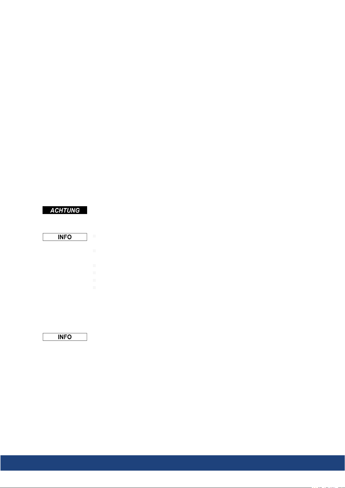
1.4 Anschlussbelegung
RS232 CAN1=CAN2
X6A Pin Signal X6B=X6C Pin Signal
1 1
2 RxD 2 CAN-Low
3 TxD 3 CAN-GND
4 4
5 GND 5
6 6
7 7 CAN-High
8 8
9 9
1.5 Einstellen der Stationsadresse und Übertragungsrate
Bei der Inbetriebnahme ist es sinnvoll, die Stationsadressen der einzelnen Verstärker und die
Baudrate für die Kommunikationvorab über die Frontplattentastatur einzustellen.
Nach Verändern der Stationsadresse und Baudrate müssen Sie die 24V-HilfsspannungsVersorgung der Servoverstärker aus- undwiedereinschalten.
Einstellungsmöglichkeiten:
Mit der Tastatur in der Frontplatte
In der Inbetriebnahme-Software auf der Bildschirmseite “CAN / Feldbus”
Über dieserielle Schnittstelle mit der Abfolge der ASCII-Kommandos:
ADDR nn → SAVE → COLDSTART (mit nn = Adresse)
CBAUD bb → SAVE → COLDSTART (mit bb = Baudrate in kB)
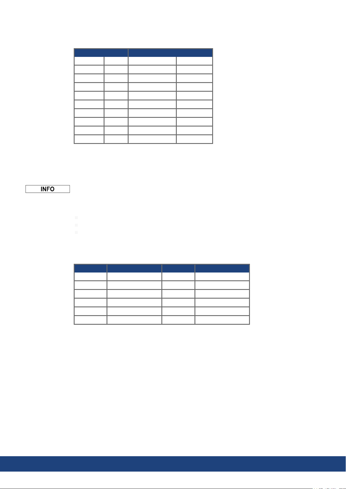
Codierung der Baudrate im LED-Display :
Codierung Baudrate in kBit/s Codierung Baudrate in kBit/s
1 10 25 250
2 20 33 333
5 50 50 500
10 100 66 666
12 125 80 800
100 1000
4 Kollmorgen | kdn.kollmorgen.com | March 2021
Page 5

2 Expansion module -2CAN-
2CAN Connector X6 of the servo amplifier is assigned to the signals for the RS232 interface
andthe CAN interface. It is therefore not the standard pin assignment for these interfaces,
anda special cable is required to be able to use both interfaces simultaneously. The-2CANexpansion moduleprovides the interfaces on separate Sub-D connectors. The two CAN
connectors are wired in parallel. A termination resistor (120Ω ) for the CAN bus can be switched into circuit if the servo amplifier is at the end of the bus.
2.1 Front view
2.2 Installation
Technical Description| 2 Expansion module -2CAN-
Beforestarting work, switch off the power to the device, i.e. neither the power supply nor the
24 V auxiliary voltagenor the operating voltage of the servo amplifier or any other connected
device may be switched on.
Use a suitable screwdriver to lever off the cover of the option slot.
Take care that no small items (such as screws) fall into the open option slot.
Screw the distance pieces into the fixing lugs of the option slot.
Place the expansion moduleonto the option slot.
Screw the screws into the threads of the distance pieces.
Plug the Sub-D9 socket into connector X6 on theservo amplifier
2.3 Connection technology
Standard shielded cables can be used for the RS232and CAN interfaces.
If the servo amplifier is the last device on the CAN bus, then theswitch for the bus termination must be set to ON.
Otherwise, the switch must be set to OFF (condition as delivered).
Kollmorgen | kdn.kollmorgen.com | March 2021 5
Page 6

Technical Description| 2 Expansion module -2CAN-
2.4 Connector assignments
RS232 CAN1=CAN2
X6A Pin Signal X6B=X6C Pin Signal
1 Vcc 1
2 RxD 2 CAN-Low
3 TxD 3 CAN-GND
4 4
5 GND 5
6 6
7 7 CAN-High
8 8
9 9
2.5 Setup of Station Address and Baud Rate
Duringsetup it makes sense to use the keypad on the front panel to preset the station addresses for the individual amplifiers and the Baud rate for communication.
After changing the station address and baud rate you must turn the 24V auxiliary supply for
the servo amplifier off and on again.
Possible ways for setup:
keypad on the front panel of the servo amplifier
setup software: screen page “CAN / Fieldbus”
serial interface with a sequence of ASCII commands:
ADDR nn => SAVE => COLDSTART (with nn = address)
CBAUD bb => SAVE => COLDSTART (with bb = baud rate in kBaud)
Codingof the Baud rate in LED display:
Coding Baud rate in kBit/s Coding Baud rate in kBit/s
1 10 25 250
2 20 33 333
5 50 50 500
10 100 66 666
12 125 80 800
100 1000
6 Kollmorgen | kdn.kollmorgen.com | March 2021
Page 7

3 Module d'expansion -2CAN-
Le connecteur X6 du variateurtransmet les signaux de l’interface RS232 et de l’interface
CAN. L’affectation des broches des interfaces ne correspond donc pas à la norme et nécessite l’utilisation d’un câble spécial si les deux interfaces doivent être utilisées simultanément.
Le module d’expansion -2CAN- présente ces interfaces séparées sur deux connecteurs
SubD. Les deux connecteurs CAN sont câblés en parallèle. Le commutateur permet
d’ajouter une résistance de terminaison (120 Ω ) au bus lorsque le variateur constitue la terminaison du bus.
3.1 Vue de face
3.2 Montage
Technical Description| 3 Module d'expansion -2CAN-
Avant de commencer le travail, mettez l'appareil hors tension, c.-à-d. ni l'alimentation ni la
tension auxiliaire24 V, ni la tension de fonctionnement du variateur ou de tout autreappareil
connecté ne doivent être allumées.
Soulever le couvercle de l’emplacement des options à l’aide d’un tournevis approprié.
S’assurerqu’aucune petite pièce (vis ou autres) ne chute dans l’emplacement ouvert.
Visser les boulons de distance dans les alésages filetés de la patte de fixation.
Placez le moduled'expansion sur l'emplacement des options.
Visser les vis dans les boulons de distance.
Mettez la douille SubD9 dans le Connecteur X6 du variateur.
3.3 Technique de raccordement
Il est possible d’utiliser du câble normalisé avec blindage pourles interfaces RS232 et CAN.
Lorsquele variateur constitue le dernier élément du bus CAN, le commutateur de ter-
minaison doit être basculé sur ON.
Sinon, le commutateur doit rester sur la position OFF (état à la livraison)
Kollmorgen | kdn.kollmorgen.com | March 2021 7
Page 8

Technical Description| 3 Module d'expansion -2CAN-
3.4 Affectation des connecteurs
RS232 CAN1=CAN2
Broche X6A Signaux Broche X6B=X6C Signaux
1 1
2 RxD 2 CAN-Low
3 TxD 3 CAN-GND
4 4
5 GND 5
6 6
7 7 CAN-High
8 8
9 9
3.5 Configuration de l’adresse de station et de la vitesse de transmission
Lors de la mise en service, il est judicieux de configurer les adresses de station des différents
variateurs et le débit en bauds pourla communication au préalable à l’aide du clavier de la pla-
tine avant.
Après avoir modifié l’adresse de station et le débit en bauds, vous devez couper, puis réenclencher l’alimentation en tension auxiliaire 24 V du variateur.
Réglages possibles:
A l’aide du clavier de la platine avant
Dans le logiciel de mise en service sur la page “CAN / Bus de terrain”
Via l’interface série, suivi des commandes ASCII:
ADDR nn → SAVE → COLDSTART avec nn = adresse)
CBAUD bb → SAVE → COLDSTART (avec bb = débits en bauds en ko))
Codage du débit en bauds sur l’affichage DEL:
Codage Débits en bauds
en kBit/s
1 10 25 250
2 20 33 333
5 50 50 500
10 100 66 666
12 125 80 800
Codage Débits en bauds
en kBit/s
100 1000
8 Kollmorgen | kdn.kollmorgen.com | March 2021
Page 9

Technical Description| 4 Modulo di espansione-2CAN-
4 Modulo di espansione -2CAN-
l connettore x6 di servoamplificatore sono assegnati i segnali dell’interfaccia RS232 e
dell’interfaccia CAN. Ciò non consente un’assegnazione standard dei pin alle interfacce ed è
necessario un cavo speciale, qualora si intenda utilizzare contemporaneamente entrambe le
interfacce. Il modulo di espansione -2CAN- permette di utilizzare le interfacce su connettori
Sub-D separati. I due connettori CAN sono cablati parallelamente. Con il commutatore è possibile inserire una resistenza di terminazione (120 Ω ) per CAN Bus, se il servoamplificatore è
l’ultimo del bus.
4.1 Vista frontale
4.2 Montaggio del modulo di espansione
Prima di iniziare il lavoro, spegnere il dispositivo, ad es. né l'alimentazione né la tensione
ausiliaria 24 V né la tensione operativa del servoamplificatore o di qualsiasi altro dispositivo
collegato possono essere accese.
Utilizzare un cacciavite adatto per rimuovere il coperchio dello slot opzionale.
Fare attenzione che nessun piccolo oggetto (come le viti) cada nello slot opzionale
aperto.
Avvitare le parti di distanza nelle barre di fissaggio della vano opzionale.
Disporre il modulodi espansione sullo vano opzionale.
Avvitare le viti nei filetti delle parti di distanza.
Inserire lo zoccolo Sub-D9 il connettore X6 da servoamplificatore.
4.3 Sistema di allacciamento
Per le interfacce RS232 e CAN è possibile utilizzare cavi standard schermati.
Se il servoamplificatore è l’ultimo dispositivo sul CAN Bus, il commutatore di terminazione
del bus deve essere posizionato su ON.
In caso contrario, il commutatore deve essere posizionato su OFF (stato al momento della
consegna).
Kollmorgen | kdn.kollmorgen.com | March 2021 9
Page 10

Technical Description| 4 Modulo di espansione-2CAN-
4.4 Assegnazione dei connettori
RS232 CAN1=CAN2
X6A Pin Segnale X6B=X6C Pin Segnale
1 1
2 RxD 2 CAN-basso
3 TxD 3 CAN-GND
4 4
5 GND 5
6 6
7 7 CAN-alto
8 8
9 9
4.5 Impostazione dell’indirizzo stazione e del Baud Rate
Durante la messa in servizio è possibile utilizzare il tastierino per impostare l’indirizzo
dell’azionamento e il baud rate.
Dopo aver modificato l’indirizzo della stazione e il baud rate occorre disinserire e reinserire la
tensione ausiliaria a 24V dei servoamplificatori.
Possibili modi per l’impostazione:
Tastierino sul frontale dell’azionamento
Software di configurazione (DriveGUI): Pagina “CAN / Fieldbus”
Interfaccia seriale con unasequenza di comandi ASCII:
ADDR nn → SAVE → COLDSTART (nn = indirizzi di stazione)
CBAUD bb → SAVE → COLDSTART (bb = baud rate in kB)
Codifica del baud rate sul display a LED:
Codifica Baudrate in kBit/s Codifica Baudrate in kBit/s
1 10 25 250
2 20 33 333
5 50 50 500
10 100 66 666
12 125 80 800
100 1000
10 Kollmorgen | kdn.kollmorgen.com | March 2021
Page 11

Technical Description|
-- / --
Kollmorgen | kdn.kollmorgen.com | March 2021 11
Page 12

Service
Kollmorgen bietet seinen Kundeneinen umfassenden Kundendienst.
.
BesuchenSie das Kollmorgen Developer Network. Stellen Sie Fra-
genan die Community, durchsuchen Sie die "Knowledge Base",
laden Sie Dateien herunter und schlagen Sie Verbesserungen vor.
Europa
KOLLMORGEN
Internet: www.kollmorgen.com/de-de
E-Mail: technik@kollmorgen.com
Tel.: +49 - 2102 - 9394 - 0
Fax: +49 - 2102 - 9394 - 3155
Nordamerika
KOLLMORGEN
Internet: www.kollmorgen.com/en-us
E-Mail: support@kollmorgen.com
Tel.: +1 - 540 - 633 - 3545
Fax: +1 - 540 - 639 - 4162
Südamerika
KOLLMORGEN
Internet: www.kollmorgen.com/pt-br
E-Mail: contato@kollmorgen.com
Tel.: +55 - 11 - 4615-6300
Asien
KOLLMORGEN
Internet: www.kollmorgen.cn
E-Mail: sales.china@kollmorgen.com
Tel: +86 - 400 668 2802
Fax: +86 - 21 6248 5367
 Loading...