

Kolida K5 PLUS User Manual

K5 PLUS GNSS
RECEIVER
User Manual
KOLIDA Instrument Company

K5 Plus GNSS
- 2 -
CONTENTS
Chapter 1 Brief Introduction ................................................................................................... - 4 -
§ 1.1 Introduction ........................................................................................................... - 4 -
§ 1.2 Production functions ............................................................................................ - 4 -
§ 1.3 Features .................................................................................................................. - 5 -
§1.4 Accessories &Components .................................................................................... - 7 -
Chapter 2 K5 PLUS Measuring System ................................................................................... - 9 -
§2.1 K5 PLUS Mainframe ............................................................................................. - 10 -
§2.1.1 The mainframe appearance ........................................................................ - 10 -
§2.1.2 Bottom interfaces ......................................................................................... - 11 -
§2.1.3 Indicator panel ............................................................................................. - 12 -
§2.1.4 Mode check and switching ........................................................................... - 13 -
§2.1.5 Self -check ..................................................................................................... - 14 -
§2.2 Handheld controller S10 ..................................................................................... - 15 -
§2.2.1 Basic introduction of the handheld ............................................................. - 15 -
§2.2.2 Blue-tooth connection .................................................................................. - 21 -
§2.2.3 Software installation and connecting ......................................................... - 23 -
§2.3 External Radio ...................................................................................................... - 25 -
§2.3.1 Radio features: ............................................................................................. - 25 -
§2.3.2 Radio appearance ........................................................................................ - 27 -
§2.3.3 Radio interface and panel ............................................................................ - 27 -
§2.3.4 Radio transmitting antenna ........................................................................ - 29 -
§2.3.5 Application Notice ........................................................................................ - 29 -
§2.4 Mainframe accessories ........................................................................................ - 31 -
§2.4.1 Instrument Case ........................................................................................... - 31 -
§2.4.2 Battery and charger ..................................................................................... - 31 -
§2.4.3 Differential antennas ................................................................................... - 32 -
§2.4.4 Multi-function data line ............................................................................... - 32 -
§2.4.5 Other accessories .......................................................................................... - 33 -
Chapter 3 Operations ............................................................................................................. - 34 -
§3.1 Static operation .................................................................................................... - 35 -
§3.1.1 Static Measurements Profile ........................................................................ - 35 -
§3.1.2 Operating procedures .................................................................................. - 36 -
§3.1.3 Field operation notes: .................................................................................. - 37 -
§3.1.4 GPS net design .............................................................................................. - 37 -
§ 3.2 RTK operations (Radio mode) ........................................................................... - 38 -
§3.2.1 Set up the Base Station ................................................................................ - 39 -
§3.2.2 Start the base station ................................................................................... - 40 -
§3.2.3 Set up rover station ...................................................................................... - 42 -
§3.2.4 Set rover station ........................................................................................... - 43 -

K5 Plus GNSS
- 3 -
§3.3 RTK operations(GPRS mode) ......................................................................... - 45 -
§3.3.1 Base and Rover installation ......................................................................... - 46 -
§3.3.2 Base and Rover settings ............................................................................... - 46 -
§3.3.3 Electronic bubble ......................................................................................... - 49 -
§3.3.4 Tilt survey ..................................................................................................... - 51 -
§3.4 Antenna height measuring ................................................................................. - 54 -
Chapter 4 Connecting to PC................................................................................................... - 56 -
§4.1 Receiver data transfer ......................................................................................... - 56 -
§4.2 INStar Operation .................................................................................................. - 57 -
§4.2.1 Data Output .................................................................................................. - 58 -
§4.2.2 Firmware update ......................................................................................... - 60 -
§4.2.3 Parameter setting ........................................................................................ - 62 -
§4.2.4 Radio setting ................................................................................................ - 62 -
§4.2.5 Receiver register........................................................................................... - 63 -
Appendix A K5 PLUS main technical specifications ...................................................... - 64 -
Appendix B GDL-20 radio technical specifications ....................................................... - 67 -
Appendix C Technical Terms ............................................................................................. - 69 -

K5 Plus GNSS
- 4 -
Chapter 1 Brief Introduction
Read this chapter, and you will have a brief knowledge of KOLIDA Company and
K5 PLUS GNSS measurement system.
§ 1.1 Introduction
Thanks for purchasing KOLIDA product! KOLIDA is a leading GNSS RTK and
surveying instrument manufacturer, has been committed itself to spread the
advanced survey techniques and products to users worldwide.
This manual takes K5 PLUS measuring system for example, to explain how to
install, set up and operate RTK system. We recommend that you read these
instructions carefully before using the instrument.
K5 PLUS, a new generation integrated RTK system with smaller size and
innovative design, leads the developing direction of new generation RTK with
excellent performance, provides high-efficiency and intelligent surveying
experience to customers. It isn’t simply smaller, it does better in everywhere.
§ 1.2 Product Functions
Control Survey: dual-band (dual-frequency) system static measurements can
accurately complete Control Survey, High-precision Deformation Monitoring,
Photo-control Point Measurement.
Highway Survey: with KOLIDA software EGStar, user can quickly complete the
encryption of the control points, road topographic mapping, cross-section
measurement, profile measurement.

K5 Plus GNSS
- 5 -
CORS Application: provide more stable and convenient data link for field
operations. It is seamlessly compatible with all types of CORS stations.
Data acquisition measurement: perfectly match various measurement software
and do data acquisition quickly and easily.
Stakeout: large-scale point, line, plane setout.
Electric Power Measurement: transmission line measurement orientation,
distance measurement, angle calculation.
Marine Survey: oceanographic research, dredging, piling, inserted row, making
the marine operations more convenient and easy.
§ 1.3 Features
Innovative structure design: K5 PLUS, with smaller size and innovative
design, the weight is only 970g, built with magnesium alloy materials. The top
edge is designed to decrease the harm in case of falling down to ground.
Dual module Bluetooth: K5 PLUS is equipped with Bluetooth 4.0 module,
support communication with smart phone, tablet PC and other digital product.
It also supports Bluetooth 2.1 standard and is able to connect with traditional
data collector.
Tilt centering and electronic bubble: The internal tilt compensator and
electronic bubble can correct the coordinate result automatically at the points
with tilt angle and tilt direction.
NFC function: The internal NFC module can make the complicated Bluetooth
communication easier and simpler. (it needs data collector which support NFC
technology)

K5 Plus GNSS
- 6 -
Full constellation support: Equipped with most advanced GNSS boards, K5
PLUS system can track signal from all of running satellite constellation,
especially support B1,B2 and B3 signal from BEIDOU, also can get positioning
result with BEIDOU signal only.
Smart and Open Platform: K5 PLUS is based on a smart and powerful platform
which can make system works faster and more stable, less power consumption,
also support smart voice guide and smart diagnosis etc.
Cloud service: The function realizes online upgrade and registration, remote
diagnosis in real-time.
Advanced data link module: K5 PLUS adopts new and excellent data link
system, which is compatible with current radio protocols in the market, also
supports all kinds of network types to access CORS seamlessly.
K5 Plus GNSS
- 7 -
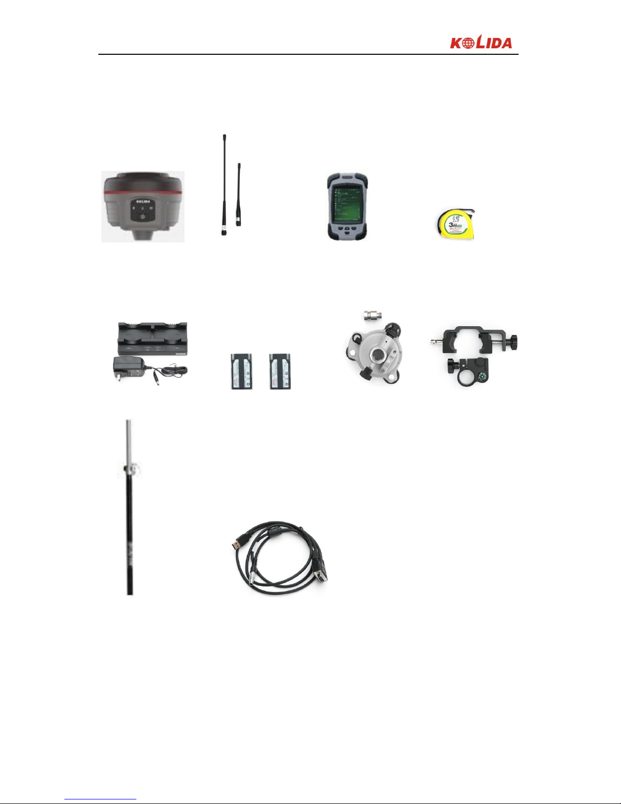
§1.4 Accessories &Components
Rover station standard configuration
Mainframe antennas S10 controller Measuring tape
Mainframe charger Mainframe batteries Tribrach & connector Bracket for controllers
Retractable pole multi-function communication cable
K5 Plus GNSS
- 8 -
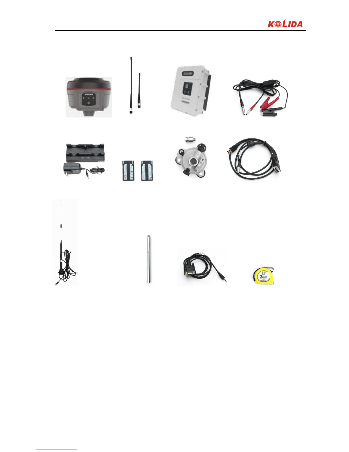
Base station standard configuration
Mainframe Antennas 25w radio Multiple communication cable
Battery charger Batteries Tribrach & connector Communication cable
Transmission antenna Support pole Frequency-change line Measuring tape
K5 Plus GNSS
- 9 -
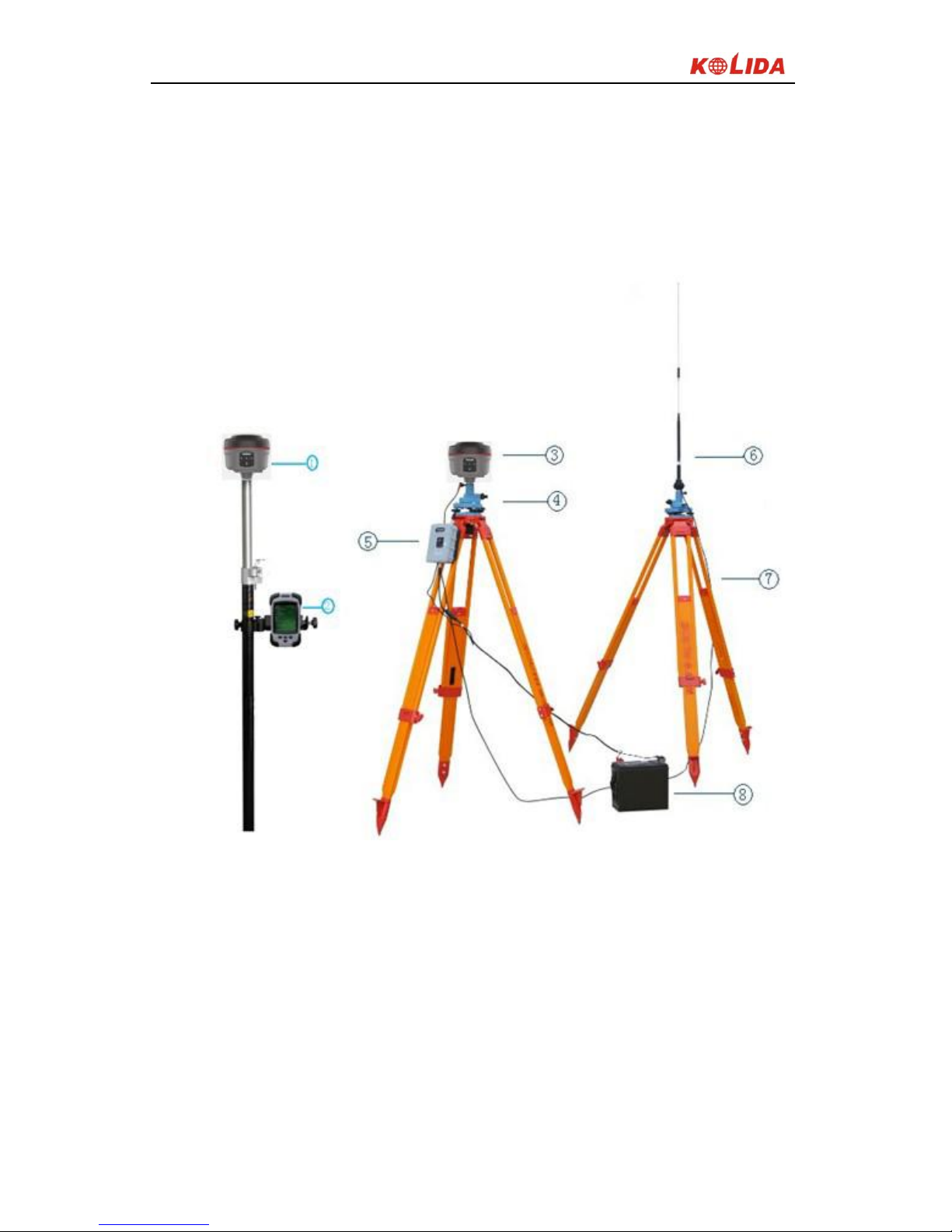
Chapter 2 K5 PLUS Measuring System
Reading this chapter, you can grasp the components, installation and the
function of K5 PLUS measuring system.
Figure 2-1
① Rover ② Controller ③Base
④ Tribrach ⑤ Radio ⑥Radio Antenna
⑦ Tripod ⑧Battery
K5 Plus GNSS
- 10 -
§2.1 K5 PLUS Mainframe
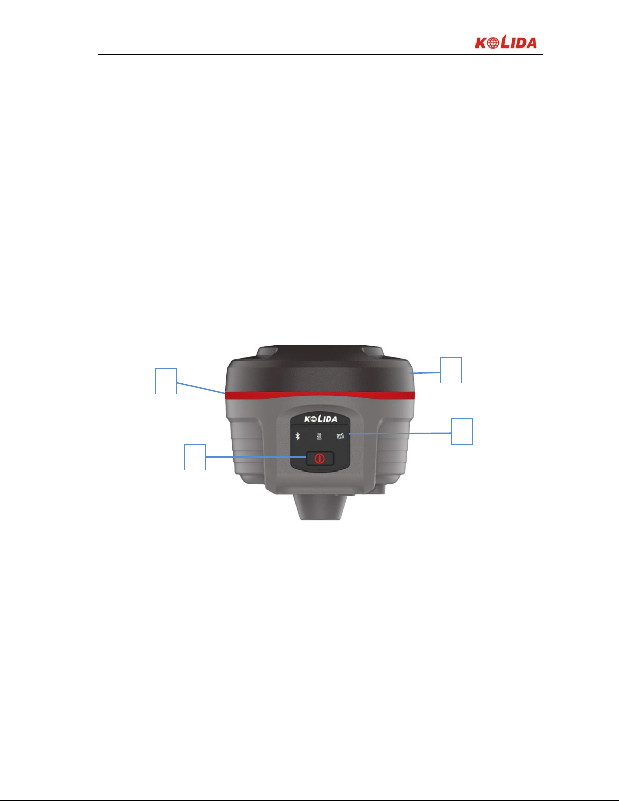
§2.1.1 The mainframe appearance
The mainframe is a flat cylindrical, 118mm in height, 134mm in diameter, the
height from the rubber seal ring to the bottom is 78mm. The front side is the
buttons and indicator panel. The bottom of the instrument is radio and network
interface, as well as the battery compartment and other interfaces; there is a
string of bar code number, which is machine number.
Front Panel
Figure 2-2
① Top cover ②Protection rubber ring ③Indicator light
④ Power Key
2 1 3
4

K5 Plus GNSS
- 11 -
Back Panel
Figure 2-3
① Battery compartment cover ②NFC label ③ Compartment locker
Machine Serial number: for registration, and identify the instrument and the
corresponding connection with data collector.
§2.1.2 Bottom interfaces
Figure 2-4
① Compartment snap-fit: for locking the battery compartment cover
② SN label
4 1 3 2 5 7 6
K5 Plus GNSS
- 12 -
③ Screw hole: fix the mainframe to the tribrach or the pole
④ Beeper: broadcast voice messages
⑤ UHF/GPRS socket: connect UHF/GPRS antenna
⑥ 5-pin cable socket: connect power cable
⑦ 7-pin data cable socket: connect data cable
5-pin interface: for connecting to the external Radio or external power;
7-pin serial port: used to connect to computer to transfer data, or handheld;
GPRS interface: Install the GPRS (GSM/CDMA/3G optional) network antennas;
UHF interface: Install UHF radio antenna;
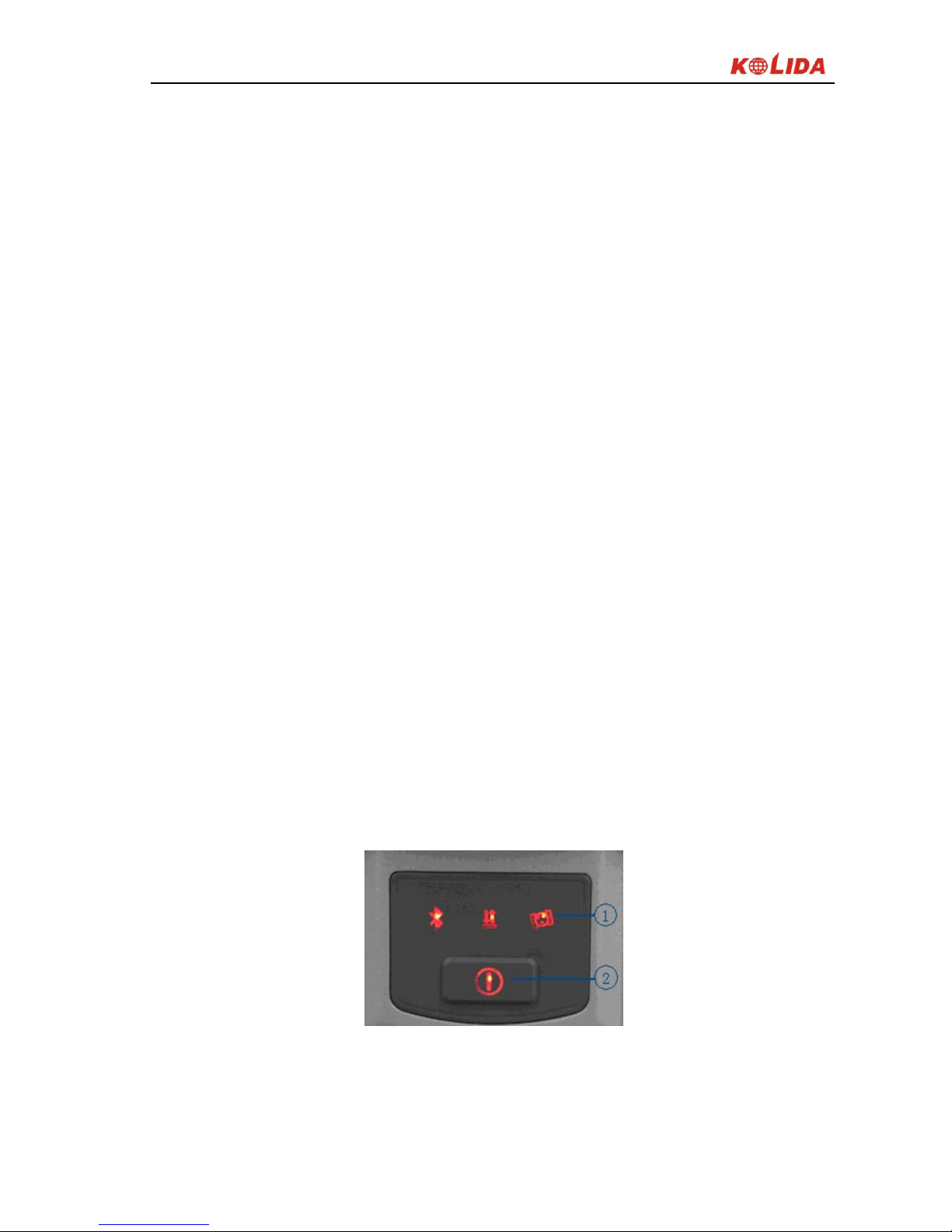
§2.1.3 Indicator panel
a) K5 PLUS mainframe indicator has two meanings:
The indicator for mode switching and working modes;
The indicator for mainframe self-check status;
b) In order to let you have a better understanding of the specific meaning of the
indicator in the two status, we will describe in detail.
K5 PLUS indicator panel has been re-designed with 3 LED indicators, simply
and clearly indicates the various status, as shown below:
Figure 2-5
①3 indicator lights ②Power key
The following are the meanings of some typical lights:
K5 Plus GNSS
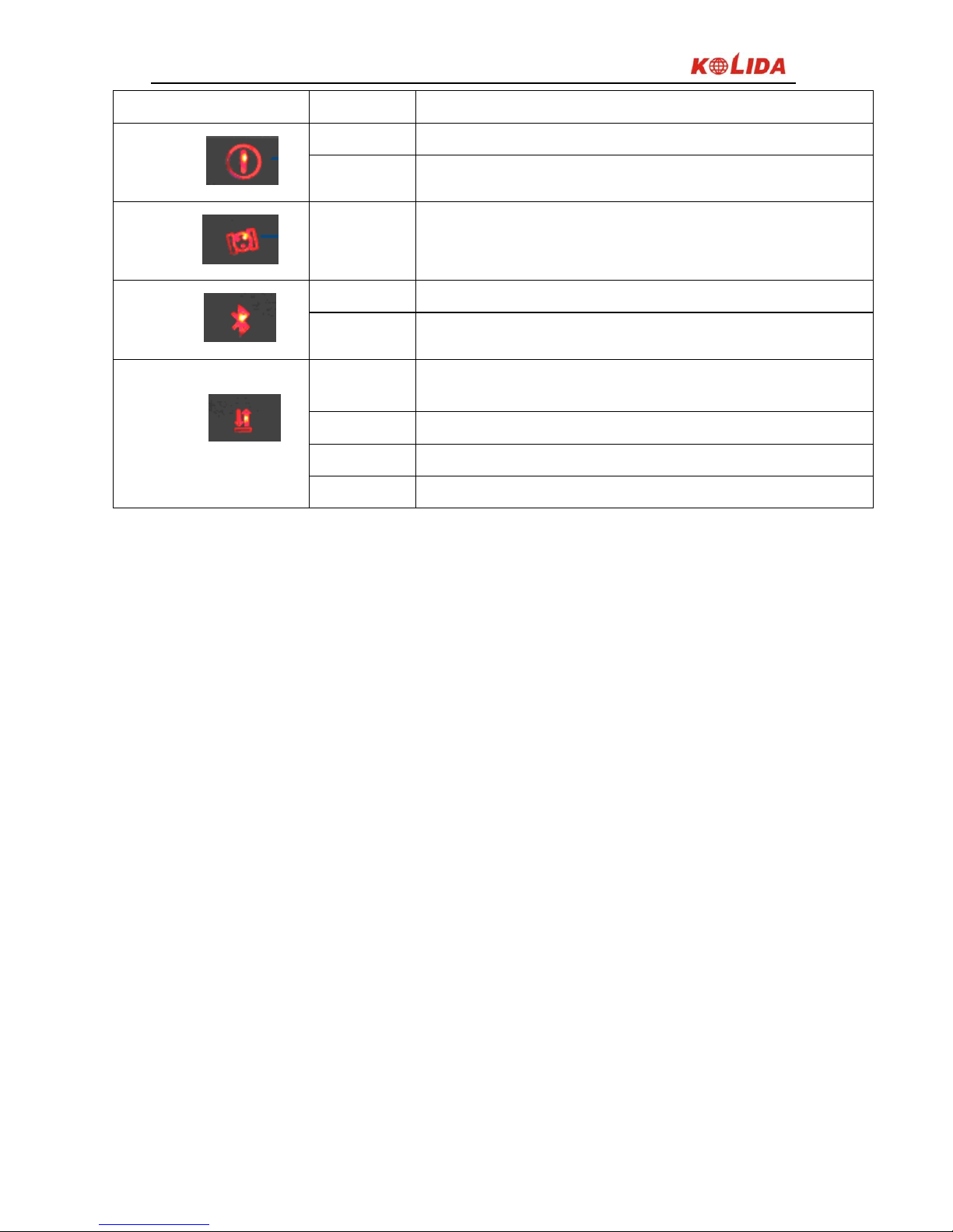
- 13 -
Indicator
Status
Meaning
POWER
on
Normal voltage, built-in battery 7.4v
blink
Low battery
Satellite
blink
Number of satellite locked, cycle once every 5 seconds
Bluetooth
off
Handheld disconnected
on
Handheld connected
Signal/data
blink
Static mode: flashing in accordance with the setting
sampling interval when recording data
on
Base or rover mode: built-in module receives strong signal
blink
Base or rover mode: built-in module receives weak signal
off
Table 2-1
§2.1.4 Mode check and switching
Mode check
In normal working mode, press power key once, there is voice message to
indicate current working status.
Mode switching
After power on receiver, use data collector to connect the receiver, then configure the
working mode and data link mode.
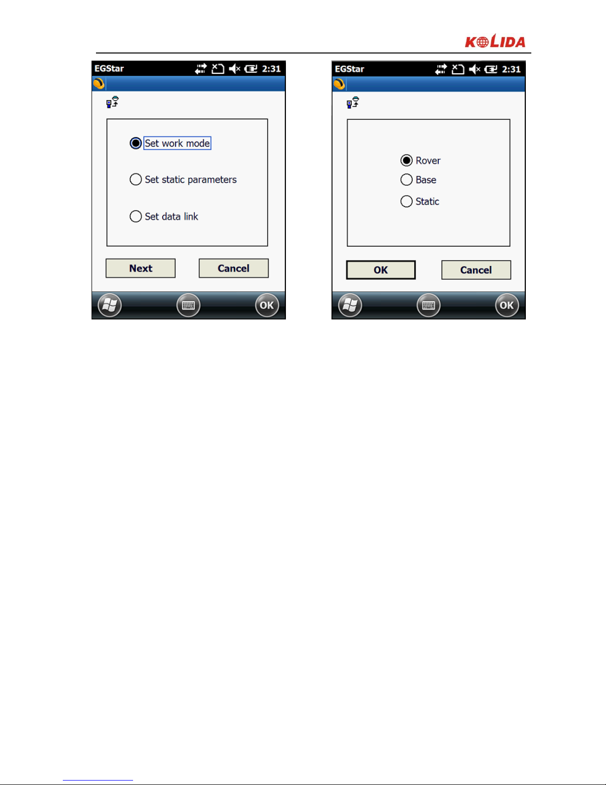
K5 Plus GNSS
- 14 -
Figure 2-6
§2.1.5 Self -check
If the panel indicator is abnormal or not working properly, you can use the
automatic detection function to run the self-check.
Power on, press and hold the <Power> button about 8 seconds, until the BT
light turns on again and along with the beeping from receiver, then release the
button to and the receiver starts performing the self-check.
If all the function parts passed self-check, there is voice message to remind, wait
a few seconds, the instrument will turns off automatically.
If the self-check isn’t passed, there is also voice message to remind, and
instrument will stay in the status of self-check, doesn’t turn off, it is to identify
the problem.
K5 Plus GNSS
- 15 -
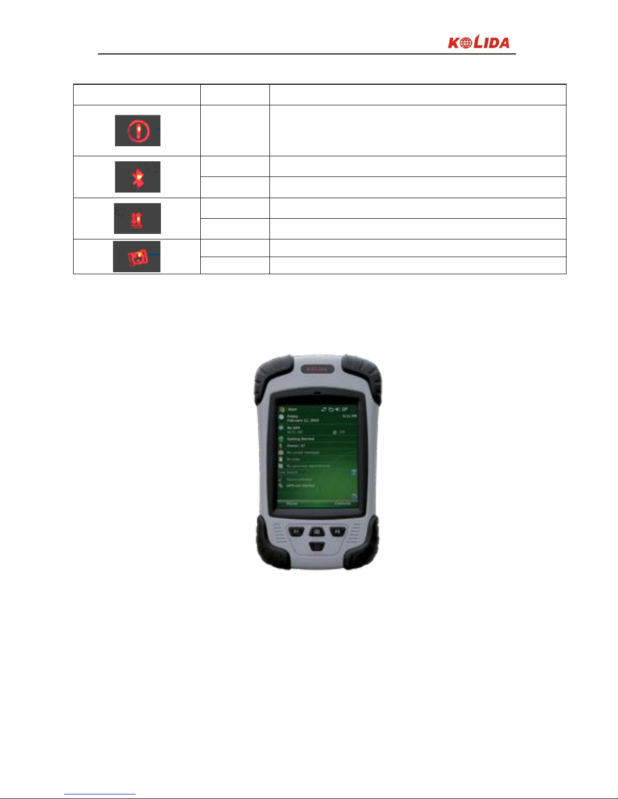
The meaning of the lights during self-check
Indicator
Status
Meaning
on
Receiver is performing the self-check
on
OEM board self-check is passed
off
OEM board self-check isn’t passed
on
GPRS/GSM module part self-check is passed
off
on
Internal radio module self- check is passed
off
Internal radio module self- check isn’t passed
Table 2-2
§2.2 Handheld controller S10
Figure 2-7
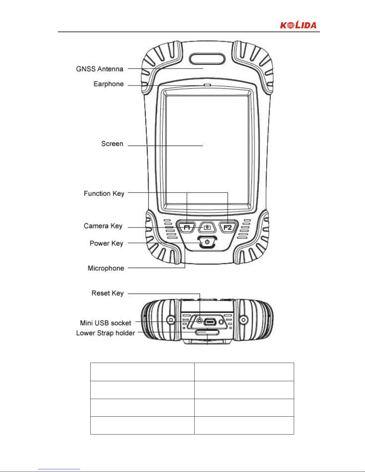
§2.2.1 Basic introduction of the handheld
Here takes S10 for example (If you want to know more about Getac controller,
please refer to the manual for Getac controller), appearance of S10:
K5 Plus GNSS
- 16 -
Figure 2-8
Standard Configuration
Description
Li-ion Battery
3.7V/ 3000 mA/h
Strap
Black, 180*12mm
Touch Pen
Black, 12.7mm
K5 Plus GNSS
- 17 -
USB data cable
1.5m
USB Charger
5V/1A
Disc
Table 2-3
1. Charging
Connect the charger with collector by the USB Link cable to recharge.
Main Screen (Upper right corner) will show the Charging Icon in power off (on)
status. (Once you connect Collector with PC to recharge; the charging time will be
longer).
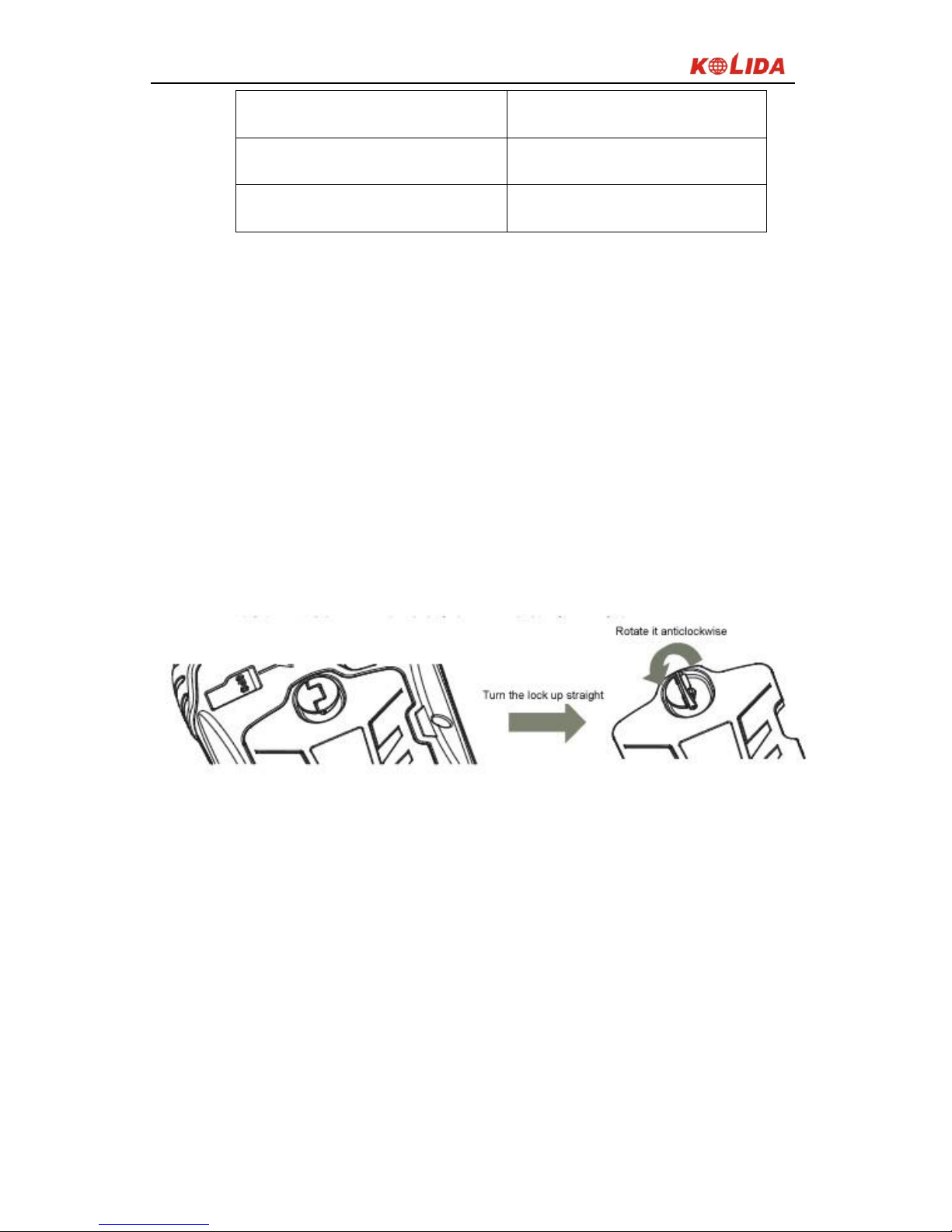
2. Installing Battery, SIM Card and Storage Card
Turn the lock up straight and rotate it anticlockwise, you can take off the battery
cover.
Figure 2-9
There are two sockets upon the battery position, left is for SIM Card and right is
for Storage Card.

K5 Plus GNSS
- 18 -
Figure 2-10
Installing the battery, turn the lock clockwise to the end.
(SIM Card: The Missing Angle Corner of SIM Card will be at the lower right
corner)
3. Power on/off
Make sure that the battery is fully charged or you can connect the Collector to PC
via the USB Cable. (Collector should be with battery).
Press Power Key for 3-5 seconds to power on/off.
(If there is no any response from Collector or other unusual situations happened,
press the Reset Key besides the USB socket in the bottom of Collector with the
Touch Screen Pen).
4. Connect to PC
Make sure that you’ve installed Microsoft ActiveSync 4.5 or higher version, if
your computer equipped with win7 or win8 system, please make sure that you
have installed Windows Mobile Device Center program.
Connect the Collector to PC via the Mini USB Data Cable.
Connection will be preceded automatically by Microsoft ActiveSync. Icon will
turn green and an interface of Setting will come out, you can just click “Cancel”.
K5 Plus GNSS
- 19 -
After this, you can manage and edit the data in Collector.
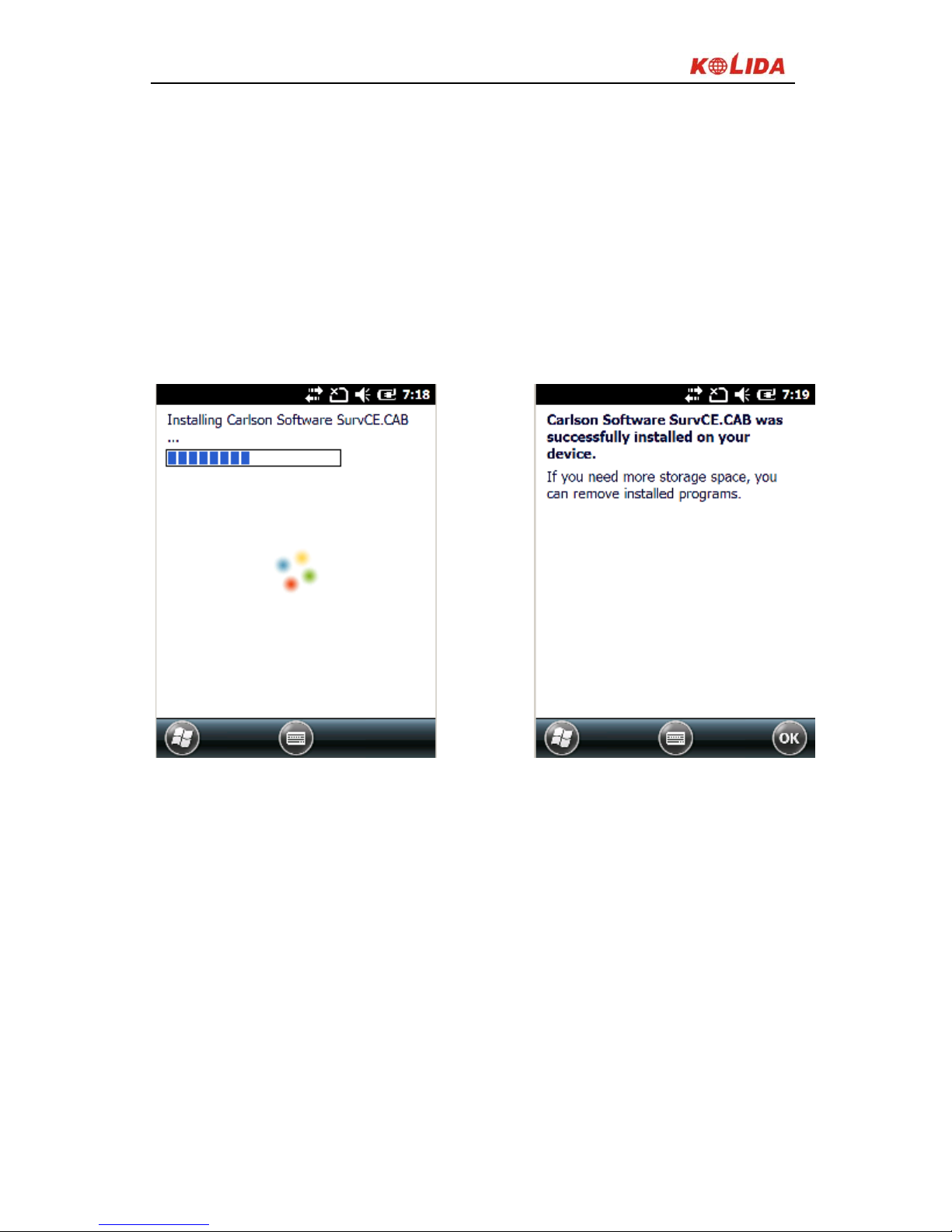
5. Installing Program
Make sure that collector is synchronized with PC. Run the Installation file at PC
side.
If the installation program is also suitable for collector, you can copy the
installation program into collector to install. You can just copy the folder into
collector when you need.
Figure 2-11
(The two operations: Upper→ Equipment, Lower→ Storage Card)
We suggest you installing programs into Flash Memory and save data into
Storage Card.
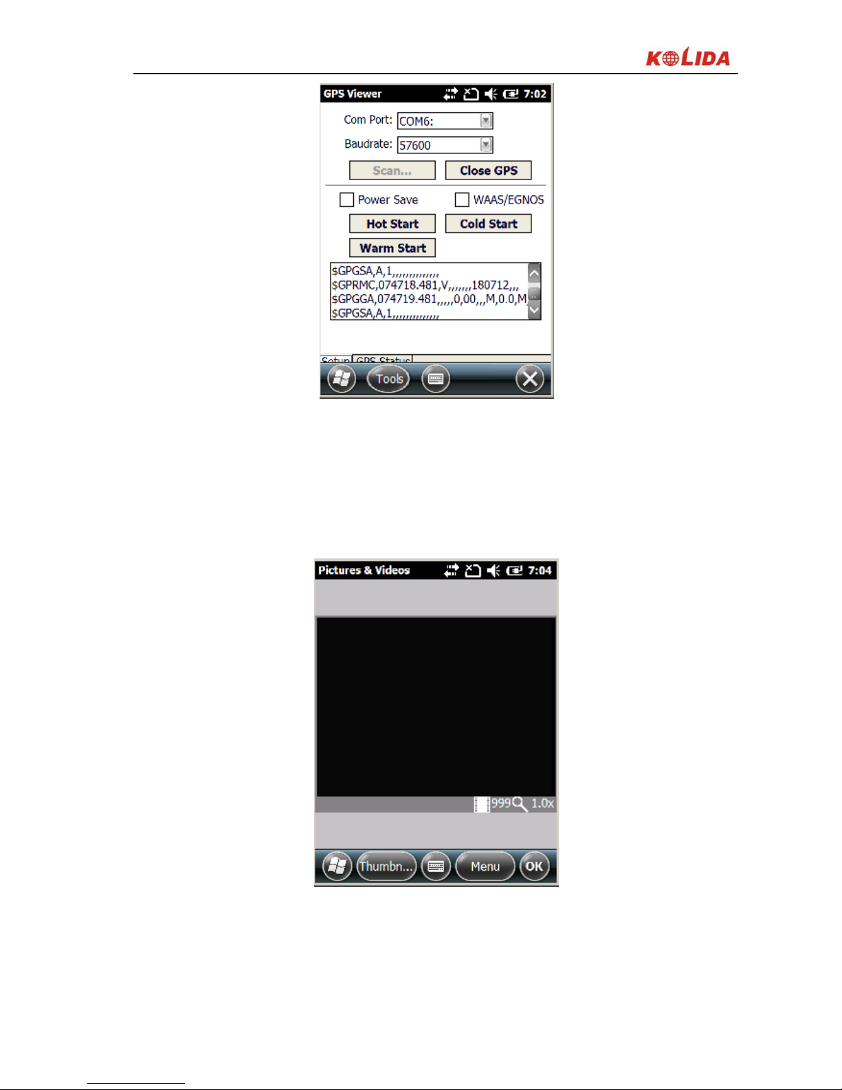
6. How to use GPS
If you want to check the working status of GPS via checking or collecting
software, please set the COM port to COM6 and the baud rate to 57600.
K5 Plus GNSS
- 20 -
Figure 2-12
7. Camera
Get into the Camera Mode by pressing the Camera Key for 3 or more seconds.
Press Camera Key to take a photo and click “OK” on the screen to save.
Figure 2-13
Note: If you want to know more information about S10, Please refer to S10
manual.

K5 Plus GNSS
- 21 -
§2.2.2 Blue-tooth connection
The short-range wireless Bluetooth communication facilities are for the
wireless exchange of information among a variety of Bluetooth-enabled devices.
Tap on the Start menu (Settings) → (control panel) to open (Bluetooth Device
Manager). tap on the(scanning device) after setting the Bluetooth device, and
the surrounding Bluetooth devices will be listed in the search list. And then
input the password 1234 to make pairing between controller and receiver. As it
shown below:
Figure 2-14
 Loading...